CN100579596C - Patient controlled drug delivery device - Google Patents
Patient controlled drug delivery deviceDownload PDFInfo
- Publication number
- CN100579596C CN100579596CCN200380109337ACN200380109337ACN100579596CCN 100579596 CCN100579596 CCN 100579596CCN 200380109337 ACN200380109337 ACN 200380109337ACN 200380109337 ACN200380109337 ACN 200380109337ACN 100579596 CCN100579596 CCN 100579596C
- Authority
- CN
- China
- Prior art keywords
- button
- plunger
- pump
- clamp
- cavity
- Prior art date
- Legal status (The legal status is an assumption and is not a legal conclusion. Google has not performed a legal analysis and makes no representation as to the accuracy of the status listed.)
- Expired - Fee Related
Links
Images


Classifications
- A—HUMAN NECESSITIES
- A61—MEDICAL OR VETERINARY SCIENCE; HYGIENE
- A61M—DEVICES FOR INTRODUCING MEDIA INTO, OR ONTO, THE BODY; DEVICES FOR TRANSDUCING BODY MEDIA OR FOR TAKING MEDIA FROM THE BODY; DEVICES FOR PRODUCING OR ENDING SLEEP OR STUPOR
- A61M5/00—Devices for bringing media into the body in a subcutaneous, intra-vascular or intramuscular way; Accessories therefor, e.g. filling or cleaning devices, arm-rests
- A61M5/14—Infusion devices, e.g. infusing by gravity; Blood infusion; Accessories therefor
- A61M5/142—Pressure infusion, e.g. using pumps
- A61M5/14212—Pumping with an aspiration and an expulsion action
- A61M5/14216—Reciprocating piston type
- A—HUMAN NECESSITIES
- A61—MEDICAL OR VETERINARY SCIENCE; HYGIENE
- A61M—DEVICES FOR INTRODUCING MEDIA INTO, OR ONTO, THE BODY; DEVICES FOR TRANSDUCING BODY MEDIA OR FOR TAKING MEDIA FROM THE BODY; DEVICES FOR PRODUCING OR ENDING SLEEP OR STUPOR
- A61M5/00—Devices for bringing media into the body in a subcutaneous, intra-vascular or intramuscular way; Accessories therefor, e.g. filling or cleaning devices, arm-rests
- A61M5/14—Infusion devices, e.g. infusing by gravity; Blood infusion; Accessories therefor
- A61M2005/1401—Functional features
- A61M2005/1405—Patient controlled analgesia [PCA]
- A—HUMAN NECESSITIES
- A61—MEDICAL OR VETERINARY SCIENCE; HYGIENE
- A61M—DEVICES FOR INTRODUCING MEDIA INTO, OR ONTO, THE BODY; DEVICES FOR TRANSDUCING BODY MEDIA OR FOR TAKING MEDIA FROM THE BODY; DEVICES FOR PRODUCING OR ENDING SLEEP OR STUPOR
- A61M5/00—Devices for bringing media into the body in a subcutaneous, intra-vascular or intramuscular way; Accessories therefor, e.g. filling or cleaning devices, arm-rests
- A61M5/14—Infusion devices, e.g. infusing by gravity; Blood infusion; Accessories therefor
- A61M5/142—Pressure infusion, e.g. using pumps
- A61M5/14212—Pumping with an aspiration and an expulsion action
- A61M5/1424—Manually operated pumps
Landscapes
- Health & Medical Sciences (AREA)
- Vascular Medicine (AREA)
- Engineering & Computer Science (AREA)
- Anesthesiology (AREA)
- Biomedical Technology (AREA)
- Heart & Thoracic Surgery (AREA)
- Hematology (AREA)
- Life Sciences & Earth Sciences (AREA)
- Animal Behavior & Ethology (AREA)
- General Health & Medical Sciences (AREA)
- Public Health (AREA)
- Veterinary Medicine (AREA)
- Infusion, Injection, And Reservoir Apparatuses (AREA)
Abstract
Description
Translated fromChinese技术领域technical field
总体来讲,本发明涉及医疗器械,具体来讲是涉及一种由患者控制的、用于自行输入药液的装置,如输入镇痛药等等。Generally speaking, the present invention relates to medical devices, and specifically relates to a device controlled by a patient for self-infusion of medical fluids, such as infusion of analgesics and the like.
背景技术Background technique
对于疼痛症状的治疗,如术后疼痛或者由于疾病或损伤而引起的疼痛,常常需要对患者进行皮下以及/或者静脉(IV)镇痛药液以及/或者麻醉药物的注射,例如对患者进行一次或多次皮下注射。如果是慢性疼痛,优选的治疗方法是使用诸如皮下注射针,向患者的静脉插入输液管,也可用“静脉点滴器”或一个流速较低、并可调的机电泵,通过输液管以缓慢或“基本”的流动流率注射药物。For the treatment of pain symptoms, such as postoperative pain or pain caused by disease or injury, it is often necessary to inject patients with subcutaneous and/or intravenous (IV) analgesics and/or anesthetic drugs, for example, once or multiple subcutaneous injections. In the case of chronic pain, the preferred method of treatment is to insert an infusion line into the patient's vein using, for example, a hypodermic needle, or an "intravenous dropper" or an electromechanical pump with a low flow rate and adjustable flow through the line at slow or The "basic" flow rate injects the drug.
许多表现出慢性疼痛症状的患者还会经历周期性的更加剧烈的疼痛,这表明需要暂时加快药物的注入速度。为实现这一目的,调整注射仪器的流速十分必要,由于患者一般地缺乏训练、技巧以及/或者体能来完成这种注射装置的调整,因此就需要训练有素的专业护理人员在现场并帮助完成。Many patients presenting with chronic pain symptoms also experience periods of more severe pain, suggesting a need for a temporary increase in the rate of drug infusion. In order to achieve this, it is necessary to adjust the flow rate of the injection device. Since patients generally lack the training, skill and/or physical ability to complete this adjustment of the injection device, it is necessary to have a trained professional nursing staff on site and to help complete it. .
根据前文,已有很多关于“患者控制镇痛”或简称“PCA”的输液装置的申请,该装置能够使患者在例如剧烈疼痛发作期间完成静脉自动输液,而无需专业护理人员的协助。这不仅在操作上简单省力,而且在使用上也安全可靠,即排除了自动输液过量的可能。According to the foregoing, there have been many applications for "patient-controlled analgesia" or "PCA" infusion devices, which enable patients to complete intravenous infusions without the assistance of professional nursing staff, for example, during episodes of severe pain. This is not only simple and labor-saving in operation, but also safe and reliable in use, that is, the possibility of automatic overdose infusion is eliminated.
这些PCA装置的例子可以在美国专利:B.Baldwin的5,084,021、K.Hiejima等人的5,891,102以及K.Hiejima等人的6,213,981中找到。Examples of these PCA arrangements can be found in US Patents: 5,084,021 to B. Baldwin, 5,891,102 to K. Hiejima et al., and 6,213,981 to K. Hiejima et al.
这些装置的共同之处在于提供了一个循环泵,其中患者通过按下泵的柱塞,来手动实现泵的“压缩”冲程,从而由静脉向患者压入标准剂量的药液,在这之后压缩弹簧与/或药物的加压源使柱塞回复到其初始位置,从而完成了泵的的再填充或“摄取”冲程。泵再填充的流率及此后患者可以自动输液的流率由放置在泵入口处的限流器来进行限制。由患者处流向泵的反向液体流可由布置在泵出口处的止回阀来完成。What these devices have in common is the provision of a circulatory pump in which the patient manually performs the "compression" stroke of the pump by depressing the plunger of the pump, thereby infusing the patient intravenously with a standard dose of medical fluid, after which the compression A spring and/or a pressurized source of drug returns the plunger to its original position, completing the pump's refill or "uptake" stroke. The flow rate at which the pump refills and thereafter the patient can be automatically infused is limited by a flow restrictor placed at the pump inlet. Reverse fluid flow from the patient to the pump can be accomplished by a check valve arranged at the pump outlet.
虽然已有的PCA装置提供了患者自动输液装置问题的部分解决方案,但是它们仍然存在一定缺陷。例如,一些装置要求患者在泵的压缩冲程过程中不断对柱塞施加压力,这可能要持续几秒甚至几分钟才能完成,一些患者可能由于身体原因而无法完成如此长时间的用力。其他装置要求患者按下泵上的第一个按钮,来完成压缩冲程,然后再按下泵上的第二个按钮来启动摄取冲程,在压缩冲程完成以后,可能在一段持续时间内要求患者监视柱塞的位置,从而知道何时再按下第二个按钮。上述装置的另一个共同缺陷在于,它们都需要延续一段时间,并且要求一位专业护理人员对装置进行谨慎操作,以在使用之前使装置“做好启动准备”,即用药液驱散装置中的所有空气,因为一旦任何空气气泡被输入到患者体内,都可能使患者体内形成致命的栓塞。Although existing PCA devices provide a partial solution to the problems of automatic patient infusion devices, they still suffer from certain deficiencies. For example, some devices require the patient to continuously apply pressure to the plunger during the pump's compression stroke, which may take seconds or even minutes to complete, and some patients may be physically unable to complete such an exertion for such a long time. Other devices require the patient to press a first button on the pump to complete the compression stroke, then press a second button on the pump to initiate the intake stroke, and may require patient monitoring for a sustained period after the compression stroke is complete The position of the plunger and thus knowing when to press the second button. Another common disadvantage of the above-mentioned devices is that they all need to be extended for a period of time and require a professional caregiver to carefully operate the device to make the device "prime ready" before use, that is, to disperse the liquid in the device. All air, because any air bubbles introduced into the patient could cause a fatal embolism in the patient.
因此,在医学领域就需要一种能满足向患者不断输液并保证一定剂量药液两个要求之一或者全部的PCA装置,在这种装置中,患者通过快速地按下一个单一按钮来完成泵的压缩冲程,自动安全地输入一定剂量的药液,而当压缩冲程完成之后又能自动启动泵的摄取冲程,而且人们可以快速地做好使用准备,而不用训练有素的专业人员来操作装置。Therefore, in the medical field, there is a need for a PCA device that can meet one or both of the two requirements of continuously infusing the patient and ensuring a certain dose of liquid medicine. In this device, the patient completes the pump by quickly pressing a single button. The compression stroke can automatically and safely inject a certain dose of liquid medicine, and when the compression stroke is completed, the intake stroke of the pump can be automatically started, and people can quickly prepare for use without the need for trained professionals to operate the device .
发明内容Contents of the invention
根据本发明,提供一种患者控制的输液装置,包括:外壳,形成有具有底端和顶端的轴向空腔;安装在空腔底端附近的泵,该泵形成有储液器,该储液器具有:固定在空腔内的第一壁;以及第二壁,该第二壁能够在空腔内相对于第一壁在满储液器位置与空储液器位置之间轴向运动;输入管,它具有与泵的入口相连的第一端以及能够与加压药液源相连的第二端;输出管,它具有与泵的出口相连的第一端以及能够皮下地连接到患者的相对的第二端;安装在空腔内的夹具,它在闭合位置与打开位置之间运动,处于闭合位置时它压缩输出管,从而防止液流通过输出管;处于打开位置时它与输出管脱离配合,从而允许液流通过输出管,该夹具被朝其闭合位置偏压;能够与储液器的第二壁配合的柱塞,其设置用于在空腔内的上升位置和下降位置之间做轴向运动,使得所述第二壁可在满储液器位置与空储液器位置之间运动;从空腔的顶端延伸出的按钮,其设置在空腔中,用于在突起位置与按下位置之间做轴向运动,其中该按钮在突起位置与按下位置之间的运动适于使得柱塞在空腔内运动,该按钮具有用于将按钮锁定在按下位置的止动件,以及凸缘,该凸缘与夹具咬合并在按钮运动到按下位置时使夹具运动到打开位置;轴向地放置在柱塞与按钮之间的压缩的弹簧;安装在空腔内的弹簧销,当按钮运动到其按下位置时,弹簧销与按钮中的止动件弹性地咬合,并克服弹簧的力,将按钮保持在其按下位置;以及柱塞上的解锁脱扣,当柱塞运动到该下降位置时,该解锁脱扣使弹簧销与按钮中的止动件脱离配合。According to the present invention, there is provided a patient-controlled infusion device comprising: a housing formed with an axial cavity having a bottom end and a top end; a pump mounted near the bottom end of the cavity, the pump forming a reservoir, the reservoir The reservoir has: a first wall secured within the cavity; and a second wall axially movable within the cavity relative to the first wall between a full reservoir position and an empty reservoir position An input tube having a first end connected to the inlet of the pump and a second end capable of being connected to a source of pressurized medical fluid; an output tube having a first end connected to the outlet of the pump and capable of being subcutaneously connected to a patient the opposite second end of the cavity; a clamp mounted in the cavity, which moves between a closed position and an open position, in which it compresses the output tube, thereby preventing flow through the output tube; in the open position, it is connected to the output tube tube disengagement, thereby allowing liquid flow through the output tube, the clamp is biased toward its closed position; a plunger engageable with the second wall of the reservoir, which is provided for a raised position and a lowered position within the cavity Make axial movement between, so that the second wall can move between the position of the full reservoir and the position of the empty reservoir; a button extending from the top of the cavity, which is arranged in the cavity, for Axial movement between a raised position and a depressed position, wherein the movement of the button between the raised position and the depressed position is adapted to move the plunger within the cavity, the button having a function for locking the button in the depressed position The stopper, and the flange, which engages with the clamp and moves the clamp to the open position when the button moves to the depressed position; a compressed spring axially placed between the plunger and the button; installed in the hollow a spring pin in the cavity that resiliently engages a stop in the button when the button is moved to its depressed position and holds the button in its depressed position against the force of the spring; and an unlock on the plunger Trip, the unlocked trip disengages the spring pin from the stop in the button when the plunger is moved to the lowered position.
根据本发明,还提供一种患者控制的输液装置,包括:循环泵、能够与泵配合的柱塞、以及能够与柱塞配合的按钮,与此结合所作的改进包括:在操作上响应于按钮在其突起与按下位置间的运动的装置,用于分别闭合与打开所述泵的输出口;用于在按钮的按下位置以可释放方式锁定按钮的装置;以及在操作上响应于柱塞向其选定位置的运动的装置,用于将按钮从其按下位置释放。According to the present invention, there is also provided a patient-controlled infusion device comprising: a circulation pump, a plunger engageable with the pump, and a button engageable with the plunger, the improvement in combination comprising: operatively responsive to the pushbutton Means for movement between its protruding and depressed positions for respectively closing and opening said pump outlet; means for releasably locking the button in its depressed position; and operatively responsive to the post A device for the movement of a plunger toward its selected position for releasing a button from its depressed position.
根据本发明的一个方面,PCA装置的设置可由患者自助输入连续的药液流或者逐次大剂量的药液,也可两种方式兼有。患者通过快速按下一个按钮自动输入单一剂量的药液,该按钮在泵输出冲程的期间持续作用,这样使得患者在输出冲程期间无需持续按下按钮,并且泵的摄取冲程在压缩冲程完成之后由装置自行启动,而不需要患者的进一步监视或行动。在本发明的另一个方面中,此新型装置可以快速地为使用做好准备,而无需专业人员来对其进行操作。According to one aspect of the present invention, the setting of the PCA device can be performed by the patient to self-input a continuous flow of medical solution or a large dose of medical solution one by one, or a combination of both. The patient automatically infuses a single dose of medication by quickly pressing a button that remains active for the duration of the pump's delivery stroke so that the patient does not have to keep pressing the button during the delivery stroke, and the pump's intake stroke is followed by the compression stroke The device activates itself without further monitoring or action by the patient. In another aspect of the invention, the novel device can be quickly ready for use without the need for a professional to operate it.
在其中的一个示范优选实施例中,本发明的新型PCA装置包括带有轴向空腔的一个长条形外壳,该轴向空腔贯穿外壳延伸,在其底端安装了一个循环泵。该泵限定了一个封闭的内部储液器,并包括固定在空腔内的一个第一壁或者基座,以及相对于固定壁可在空腔内轴向运动的一个第二柔性壁,与固定壁相比,可在满储液器与空储液器位置之间做轴向运动。该泵包括一个入口,该入口可通过一根输入管与一种药液加压源相连,并包括一个出口,该出口通过一根输出管与患者皮下相连,两根导管均从外壳的底部伸出。在一个优选的实施例中,泵的入口与出口均设置在装置上,这样在装置的一个选定准备方向上,出口位于高于入口的位置,用于快速地准备好输液装置。In one of the exemplary preferred embodiments, the novel PCA device of the present invention comprises an elongated housing with an axial cavity extending through the housing, at the bottom end of which is mounted a circulation pump. The pump defines a closed internal reservoir and includes a first wall or base fixed within the cavity, and a second flexible wall axially movable within the cavity relative to the fixed wall, and the fixed Axial movement between a full reservoir and an empty reservoir position is possible compared to the wall. The pump includes an inlet connectable to a pressurized source of medical fluid through an inlet tube and an outlet connected subcutaneously to the patient through an outlet tube, both conduits extending from the bottom of the housing. out. In a preferred embodiment, both the inlet and the outlet of the pump are arranged on the device, so that in a selected preparation direction of the device, the outlet is located higher than the inlet for quick preparation of the infusion device.
在空腔内安装了一个夹具,它可以在闭合与打开两种位置之间运动,闭合时它压缩输出管,从而防止药液流通过导管;打开时它与输入管脱离配合,从而允许药液流通过导管。通过一个弹簧,夹具有弹性地偏向处于其闭合位置。A clamp is mounted within the cavity and is movable between a closed position that compresses the output tube, preventing flow of drug through the tube, and an open position that disengages the input tube, allowing the drug to flow flow through the conduit. The clip is resiliently biased in its closed position by a spring.
在空腔内泵的上方限定一个长条形柱塞,用于在上升及下降位置之间作轴向运动,并且它具有与泵的活动壁相接触的下端。在空腔内柱塞的上方还限制了一个长条形的按钮,用于在突起及按下位置之间作轴向运动。按钮在其内部包括一个用于在按下按钮后将其锁定的止动件,及一个与夹具相咬合的凸缘,当按钮运动到其按下位置时,移动夹具到其打开位置。在装置的一个示范实施例中,按钮在其下端包括一个轴向孔,其中柱塞的上部与该孔共轴放置,用于做相对于轴向的滑动。在柱塞与按钮之间,轴向地放置了一个压缩弹簧。An elongated plunger is defined above the pump in the cavity for axial movement between raised and lowered positions and has a lower end in contact with the movable wall of the pump. An elongated button is also restricted above the plunger in the cavity for axial movement between the protruding and pressed positions. Inside the button is a stop that locks the button once it is pressed, and a lip that engages the clamp and moves the clamp to its open position when the button is moved to its depressed position. In an exemplary embodiment of the device, the button comprises an axial hole at its lower end, wherein the upper part of the plunger is positioned coaxially with the hole for sliding relative to the axial direction. Between the plunger and the button, a compression spring is placed axially.
安装在外壳的空腔中的弹簧销,当按钮运动到其按下位置时,与止动件弹性地咬合,并克服压缩弹簧的向上驱动力将按钮保持在该位置,直到柱塞运动到其下降位置时,柱塞上的解锁脱扣将弹簧销与按钮上的止动件弹簧销脱离配合。A spring pin mounted in a cavity in the housing, when the button is moved to its depressed position, resiliently engages the stop and holds the button in that position against the upward urging force of the compressed spring until the plunger moves to its In the lowered position, an unlock trip on the plunger disengages the spring pin from the stop spring pin on the button.
在装置上可以安装一个可选的旁路导管,它将泵上游的输入管与夹具下游的输出管连接起来,这样就可独立于泵或患者的活动,向患者持续地或者基本地输入药液。在泵的输入管内可以插入一个孔嘴(orifice),以调节药液流进入泵的流率,并因此而调节了向患者安全输入药液的流率。另外,可以在旁路导管内插入一个孔嘴,用于调节向患者输入的基本药液流的流率。An optional bypass conduit can be installed on the device, which connects the input tubing upstream of the pump to the output tubing downstream of the clamp, allowing continuous or substantial infusion of medication to the patient independent of pump or patient movement . An orifice may be inserted into the inlet tube of the pump to regulate the flow rate of the fluid flow into the pump and thereby regulate the flow rate of the fluid safely delivered to the patient. In addition, an orifice may be inserted in the bypass conduit for regulating the flow rate of the basal flow of fluid delivered to the patient.
在PCA的另外一个示范优选实施例中,装置设置了一个可拆卸的预备凸片,该翼片贯穿外壳的一个侧壁延伸,并与夹具及按钮的锁定指部咬合,这样,夹具就保持在其打开位置,而与按钮的位置无关,并且将按钮保持在其按下位置,而与柱塞的位置无关。通过将按钮压下到其按下位置,将装置定位于选定的准备方向上,并将输入管与药液加压源相连,预备凸片使得装置的准备工作迅速完成,省时省力。准备好装置,并做好使用准备之后,就可以轻松地将预备凸片拆卸下来并丢弃。In another exemplary preferred embodiment of the PCA, the device is provided with a removable preparation tab extending through one side wall of the housing and engaging the locking finger of the clamp and button so that the clamp remains in place. Its open position, regardless of the position of the button, and holds the button in its depressed position, regardless of the position of the plunger. By depressing the button to its depressed position, positioning the device in the selected preparation direction, and connecting the input tube to the pressurized source of the medical fluid, the preparation tab allows the preparation of the device to be completed quickly, saving time and effort. Once the unit is prepared and ready to use, the prep tabs can be easily removed and discarded.
参照以下的本发明的详细说明,特别是对照附图,新型PCA装置的上述的以及其他的特征和优点将更容易理解。The above and other features and advantages of the novel PCA device will be more readily understood with reference to the following detailed description of the invention, particularly with reference to the accompanying drawings.
附图说明Description of drawings
图1是根据本发明的患者自动输液装置的一个示范优选实施例的正视图;1 is a front view of an exemplary preferred embodiment of the patient automatic infusion device according to the present invention;
图2是装置顶部的侧视图;Figure 2 is a side view of the top of the device;
图3是装置的柱塞、循环泵、夹具与输出管的局部分解视图,其中,所示夹具处于闭合位置,并与压缩输出管与其咬合。Figure 3 is a partial exploded view of the plunger, circulation pump, clamp and output tube of the device, with the clamp shown in the closed position and engaged with the compressed output tube.
图4是装置沿图1中线4-4所截取截面的横截面侧视图,图中示出了在泵的输出冲程开始之前的一霎那各元件的相对位置,其中,按钮、柱塞以及泵的活动壁分别处于突起、上升及空储液器的位置,并且其中所示装置的预备凸片贯穿装置外壳侧壁上的一个孔,并将夹具保持在其打开位置;Fig. 4 is a cross-sectional side view of the device taken along line 4-4 in Fig. 1, showing the relative positions of the elements at a moment before the start of the pump's output stroke, wherein the button, plunger and pump The movable wall is in the raised, raised and empty reservoir positions, respectively, and wherein the preparation tab of the device shown penetrates a hole in the side wall of the device housing and holds the clamp in its open position;
图5是与图4相似,是装置的横截面侧视图,只是示出的是泵的输出冲程运行中间一刻各元件的相对位置,其中,所示的装置的按钮在其按下的位置被锁定;Figure 5 is a cross-sectional side view of the device similar to Figure 4, except showing the relative positions of the components at a moment in the middle of the pump's delivery stroke, wherein the button of the device is shown locked in its depressed position ;
图6与图4与图5相似,是装置的横截面侧视图,只是示出的是泵的输出冲程运行刚结束后各元件的相对位置,其中,柱塞与泵的活动壁分别处于较低及空储液器的位置,并且其中所示的装置的按钮已回复到突起的位置;Fig. 6 is similar to Fig. 4 and Fig. 5, and is a cross-sectional side view of the device, only showing the relative positions of the components after the output stroke of the pump has just ended, wherein the plunger and the movable wall of the pump are respectively at a lower position. and the position of the empty reservoir with the button of the device shown therein returned to the raised position;
图7与图4相似,是装置的内侧视图,去掉了装置的部分外壳、泵、柱塞及按钮,以显示夹具与部分输出管,其中,示出的预备凸片将夹具保持在其打开位置并使其与输出管脱离配合;Figure 7 is a view similar to Figure 4 of the inside of the device with part of the housing, pump, plunger and button removed to show the clamp and part of the output tube, with the prepared tab shown holding the clamp in its open position and disengage it from the output tube;
图8是装置的侧视图,示出的是从装置上拆卸下来的预备凸片;Figure 8 is a side view of the device, showing the preparation tab removed from the device;
图9与图7相似,是装置的部分横截面与内侧的正视图,其中,所示按钮处于按下的位置被锁定,所示夹具罩从装置上拆卸下来以显示出按钮凸缘,凸缘与夹具咬合,并将其保持在其打开位置与输出管脱离配合;Figure 9 is similar to Figure 7 and is a partial cross-section and inside front view of the device with the button shown locked in the depressed position and the clamp cover shown disassembled from the device to show the button flange, flange engages the clamp and holds it in its open position disengaged from the output tube;
图10与图9相似,是装置的内侧视图,示出的是去掉按钮及弹簧加偏压于夹具使其偏向压缩输出管,并与其咬合的闭合位置;Figure 10 is a view similar to Figure 9 and showing the inside of the device in its closed position with the push button removed and the spring biased clamp biased towards the compressed output tube and engaged therewith;
图11A-11C显示的是图11A沿线11C-11C所截取的截面,分别是按钮的前侧视图、后侧视图及其横截面视图;Figures 11A-11C show sections taken along the
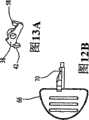
图12A与12B分别是预备凸片的前侧透视图与前平面视图;12A and 12B are a front perspective view and a front plan view, respectively, of a preparation tab;
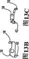
图13A与13C分别是夹具的前侧透视图、前平面视图以及底面视图;13A and 13C are a front perspective view, a front plan view, and a bottom view, respectively, of the jig;
图14A与14B分别是夹具罩的前侧透视图与后侧透视图;14A and 14B are front and rear perspective views, respectively, of the jig cover;
图15与图10相似,是装置的内侧视图;以及Figure 15 is a view similar to Figure 10 and is an inside view of the device; and
图16是装置的内侧视图的分解透视图。Figure 16 is an exploded perspective view of the inside view of the device.
具体实施方式Detailed ways
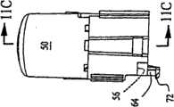
根据本发明患者自动输液(“PCA”)装置10的一个示范优选实施例示于图1的正视图中。装置10包括一个具有分别敞开的顶端与底端14与16的长条形外壳12,例如,如图7所示,以及一个贯穿其中延伸的轴向空腔18。在附图的具体示范实施例中,外壳用硬质塑料材料注塑成形,并包括两个互相联结在一起的蛤壳侧壁12A与12B,例如,用一种粘结剂沿着贯穿装置延伸的中间平面将两个侧壁粘结起来。An exemplary preferred embodiment of a Patient Automated Administration ("PCA") set 10 in accordance with the present invention is shown in front view in FIG. 1 .
如图4-6的横截面视图所示,循环泵20安装在外壳12的空腔18内,位于外壳12的底端16处。泵限定了一个用于灌装药液的封闭储液器22,并包括一个固定在空腔内抵抗运动的第一壁或者基座24,以及可在空腔内相对于固定壁在满储液器(见图4)与空储液器(见图6)之间做轴向运动的一个第二柔性壁26。As shown in the cross-sectional views of FIGS. 4-6 , the
泵20包括一个入口28以及一个出口30。输出管34的一端与入口相连,另一端通过诸如鲁尔配合(Luer fitting)(未示出)可与药液加压源(未示出)连接,而加压药液源可以包括诸如一个已知类型的电机灌流泵。出口通过诸如皮下注射针(未示出)由输出管34可与患者皮下相连。在一个优选实施例中,输入管与输出管包括透明的、柔性的医用输液管,并穿过一个保护性的柔性索环36从外壳12的底端16处伸出。
在空腔内安装了一个夹具38,它可以在闭合与打开位置之间运动,闭合时它压缩输出管34(见图10与15),从而防止药液流通过导管;打开时它与输出管脱离配合(见图7与图9),从而允许药液流通过导管。一个弹簧40使夹具有弹性地偏向处于其闭合位置。可以看出,闭合夹具时,泵20的流出物将堆积起来,这样储液器22就能够通过泵的入口28吸入或者重新填充加压药液,打开夹具时可以使泵通过其出口30排出储液器中的药液。A
在图中示出的具体示范实施例中,夹具38包括一个可旋转地安装在外壳12的侧壁12B上的杠杆臂,用于在其闭合与打开位置间运动,并包括一个锲形的卡爪42,卡爪42相对于侧壁上的弓形基准面44,压缩输出管34,在弓形基准面的上方是输出管的环套35,它位于泵20的外部而位于外壳的内部(见图15和图16)。夹具罩46(见图14A、14B及16)用于将输出管的内部部分限制在基准面(anvil)上,并使夹具转动。In the specific exemplary embodiment shown in the figures, the
如图4-6的横截面视图所示,长条形柱塞48被限制在外壳12的空腔18内,位于泵20的上方,用于在上升位置(见图4)及下降位置(见图6)之间作轴向运动。柱塞的下端与泵的活动壁26相接触,并且其形状与固定壁或基座24的内部形状相一致。可以看出,如果夹具38处于其打开位置,施加于柱塞上的向下的力将使柱塞从上升位置(参见图4)向下运动,因此而推动泵的活动壁朝向固定壁运动(参见图5),直到活动壁完全嵌入固定壁中(参见图6),因此而完成了泵的一个输出冲程,并从泵的储液器22中向患者排出一定剂量的药液。还可以看出,如果接下来闭合夹具,药物的加压源将开始用新剂量的药物填充储液器,同前文一样,这将使活动壁远离固定壁运动,并且将柱塞升高到其初始的凸起位置,如前文所述。As shown in the cross-sectional views of FIGS. 4-6, an
患者通过长条形按钮及压缩弹簧52作为媒介,间接地按下了柱塞48,按钮限制在外壳12的空腔18内柱塞的上方,用于在突起位置(见图4与图6)与按下位置(见图5)间作轴向运动,压缩弹簧52轴向地置于柱塞与按钮之间。在附图所示的具体示范实施例中,按钮包括一个延伸通过它的下端的轴向孔,和柱塞的上部共轴置于孔中,用于在其中滑动产生一轴向运动,因此限制压缩弹簧,得到被更加紧密压缩的装置10。The patient presses the
按钮包括用于将按钮锁定在其按下位置的一个止动件54,以及与夹具38相咬合的一个凸缘56,当按钮运动到其按下位置时,凸缘使夹具处于其打开位置,如图9所示。如图9所示,当将按钮(如横截面所示)压入到其按下位置时,按钮的凸缘将咬合于夹具杠杆臂上的一个突起部分58,并使其旋转到打开位置,因此使泵20中的药液流出,如前文所述。并且,锁定止动件与安装在空腔18内的弹性弹簧销60咬合,偏心自锁配合,这可以将按钮保持在其按下的位置并克服压缩弹簧52的向上的力。The button includes a
按钮向其按下位置的运动还将相对于柱塞48使压缩弹簧52压缩(见图5),导致在柱塞相对于泵20的活动壁26的相应向下运动及泵的相应输出冲程,如前文所述。这样,患者仅通过简单、快速地将按钮按到其按下位置,就可以实现随后的泵的完整输出冲程,由于装置中的药流在泵与患者之间存在阻力,一般这需要延续一段时间。然而,由于按钮锁定于其按下位置,如前文所述,患者在冲程的全部过程中就无需不断地向按钮施加持续的力。Movement of the button to its depressed position will also compress the
为使按钮在泵20的输出冲程结束之后能够自动回复到其突起位置(见图6),在柱塞48上设置了一个铲斗状的解锁脱扣62,当柱塞到达其下降位置时,解锁脱扣62抓住弹簧销60的一端,并使其与按钮上的锁定止动件54脱离配合。当按钮回复到其突起位置时,就松弛压缩弹簧52的压缩,并且,释放夹具38使其回复到闭合位置,因此启动了泵的吸入冲程,如前文所述。这样,泵的吸入冲程是自动完成的,对于患者不需要对装置10进行操作或监视。In order to enable the button to automatically return to its protruding position (see Figure 6) after the output stroke of the
在另外一个优选的实施例中,本发明的PCA装置10可以以既快捷又简便的程序为使用做好准备。如图3-5所示,泵20的入口28与出口30分别这样设置在装置上,在装置选定的一个停止方向上,出口的置于高于入口的位置,这样储液器22内的药液中的任何空气气泡均由于重力作用直接排向出口。这可以通过简单地将装置10沿其一侧放置在诸如桌子上来完成,这样就可以使得出口高于入口,如图8所示。如图所示,图标“此面朝上备用”可以用在向上的一侧上,作为操作者的帮助。In another preferred embodiment, the
如图11A与11B所示,在按钮上设置了一个弹性锁定指部64,如图7与图8所示,在外壳12的一个侧壁内的孔68中,插入了一个可拆卸的预备凸片66,它与夹具38以及按钮的锁定指部相咬合,这样使得夹具保持在其打开位置,而与按钮的位置无关,按钮保持在其按下位置,而与柱塞48的位置无关。基于这个目的,预备凸片包括一个缺口70(见图12A、12B),它与夹具上的锲形卡爪42相咬合,并将其保持在其打开位置,如图7所示,即使按钮是在上升过程,或者已经到达其突起位置。这种设置提供了另外的一个好处就是,如果装置10在使用前在仓库中贮存了一段较长的时间,预备凸片可防止夹具在这段贮存期间使柔性输出管形成永久压缩变形。As shown in Figures 11A and 11B, an
按钮上的弹性锁定指部64包括一个倾斜齿72(见图11A),当按钮被按下到其按下位置时,倾斜齿72滑动并将预备凸片66卡住。这样,即使按钮连锁地将柱塞48按下到其较低的位置时,也能使得柱塞的解锁脱扣62使弹簧销60与按钮上的锁定止动件54脱离配合,按钮仍保持在其按下位置,并且因此,柱塞也相应地保持在其较低的位置。此前的设置既使夹具38保持在其打开位置,又使泵20的储液器22的体积减小到其最小的尺寸,即减小到泵的固定壁24与活动壁26之间的狭窄空间,如图6所示。在这种结构下,仅使用相当少量的药液就可以快速地将泵准备好。The
这样,在装置10的一个优选实施例中,将预备凸片66插入到合适位置上的情况下,制造、贮存并应用装置。然后用最少的操作对装置进行快速准备,通过:1)将装置从任意无菌包装中拆卸下来;2)将按钮运动到其按下位置;3)将装置放置在其一侧表面上,或者将其保持在选定的准备方向上(“此面向上备用”);4)将输入管32的远端与加压药液源相连。药液迅速地填充输入管及体积已最小化的泵20的储液器22中,并将其中的空气向前推进,最后从升高的出口30以及输出管34排出。将装置准备好之后,预备凸片可以简便地拆卸下来并丢弃,而在按钮回复到其突起位置时,夹具38将输出管闭合,然后储液器开始填充初始剂量的药物。在输出管上可以设置一个已知类型的管夹73(见图2),以控制药液流在准备操作过程中通过装置的速度。Thus, in a preferred embodiment of the
如上文所述,PCA装置10使患者能够实现逐次、大剂量的药液输液。另外,如图4-6所示,通过设置泵20的一个旁路导管74,装置还可以制成连续、基本的药物输液,而无需患者操作,旁路导管74具有与泵上游的输入管32相连的第一端,以及与夹具38下游的输出管34相连的一个相对第二端。通过旁路导管74的药液流绕过泵的储液器22,这样就直接通过输出管输入到患者处。在旁路导管上可以设置一个限流器76,如一个玻璃孔嘴,用于调节输入给患者的药液的基本流量或连续流量的流率。As noted above, the
另外,或可选地,可以在泵20的输入管32上设置一个第二限流器78,用于调节药液重填进泵的流率,进而调节患者可以自动输入逐次剂量药物的最大流率,因此排除自动输入过量的可能。In addition, or alternatively, a
现在本领域技术人员将会清楚,在不背离其实质与范围的情况下,可对本发明的PCA装置10的材料与方法进行多种可能的变化与改进。It will now be apparent to those skilled in the art that many possible changes and modifications may be made in the materials and methods of the
例如,如图1所示,可以在装置10的外壳12上设置一个弹性夹80,这样可以方便地挂上患者的衣服或床上用品。另外,如图2所示,在柱塞48上可以设置一个指示器82,并且在装置的外壳12上可形成一个相应的窗84,通过这个窗可以看到指示器,这样柱塞相对于其上升(满储液器)与下降(空储液器)位置的轴向位置通过外壳可以轻松地看到。For example, as shown in FIG. 1, an
根据前面的例子,本发明的范围不应局限于这里所描述说明的具体实施例,在本质上它们仅仅作为示范。更适当地,本发明的范围应与权利要求及其功能等同物相当。In light of the foregoing examples, the scope of the present invention should not be limited to the specific embodiments illustrated herein, which are merely exemplary in nature. Rather, the scope of the invention should be commensurate with that of the claims and their functional equivalents.
Claims (10)
Translated fromChineseApplications Claiming Priority (2)
| Application Number | Priority Date | Filing Date | Title |
|---|---|---|---|
| US10/335,310US6936035B2 (en) | 2002-12-31 | 2002-12-31 | Patient controlled drug administration device |
| US10/335,310 | 2002-12-31 |
Related Child Applications (1)
| Application Number | Title | Priority Date | Filing Date |
|---|---|---|---|
| CN2009102536046ADivisionCN101843938B (en) | 2002-12-31 | 2003-12-26 | Patient controlled drug administration device |
Publications (2)
| Publication Number | Publication Date |
|---|---|
| CN1744924A CN1744924A (en) | 2006-03-08 |
| CN100579596Ctrue CN100579596C (en) | 2010-01-13 |
Family
ID=32655319
Family Applications (2)
| Application Number | Title | Priority Date | Filing Date |
|---|---|---|---|
| CN200380109337AExpired - Fee RelatedCN100579596C (en) | 2002-12-31 | 2003-12-26 | Patient controlled drug delivery device |
| CN2009102536046AExpired - Fee RelatedCN101843938B (en) | 2002-12-31 | 2003-12-26 | Patient controlled drug administration device |
Family Applications After (1)
| Application Number | Title | Priority Date | Filing Date |
|---|---|---|---|
| CN2009102536046AExpired - Fee RelatedCN101843938B (en) | 2002-12-31 | 2003-12-26 | Patient controlled drug administration device |
Country Status (16)
| Country | Link |
|---|---|
| US (1) | US6936035B2 (en) |
| EP (1) | EP1581288B1 (en) |
| JP (2) | JP4861623B2 (en) |
| KR (1) | KR101066819B1 (en) |
| CN (2) | CN100579596C (en) |
| AU (1) | AU2003300408B2 (en) |
| BR (1) | BRPI0317802B1 (en) |
| CA (1) | CA2511985C (en) |
| CO (1) | CO5700800A2 (en) |
| EC (1) | ECSP055901A (en) |
| MX (1) | MXPA05007135A (en) |
| NO (1) | NO20053224L (en) |
| NZ (1) | NZ541473A (en) |
| RU (1) | RU2344841C2 (en) |
| WO (1) | WO2004060453A1 (en) |
| ZA (1) | ZA200505265B (en) |
Families Citing this family (41)
| Publication number | Priority date | Publication date | Assignee | Title |
|---|---|---|---|---|
| AU2005306461B2 (en) | 2004-11-19 | 2011-01-20 | Curlin Medical Inc. | Controlled-volume infusion device |
| JP4898183B2 (en)* | 2005-10-19 | 2012-03-14 | オーベクス株式会社 | Chemical self-injection system |
| EP2083800A4 (en)* | 2006-10-19 | 2016-10-12 | Ambu As | DEVICE AND METHOD FOR ADMINISTRATION OF A BOTTLE ACTIVATED BY THE PATIENT |
| EP2175912A2 (en)* | 2007-06-25 | 2010-04-21 | Tecpharma Licensing AG | More easily usable administering device |
| CA2753214C (en) | 2009-02-27 | 2017-07-25 | Tandem Diabetes Care, Inc. | Methods and devices for determination of flow reservoir volume |
| US9250106B2 (en) | 2009-02-27 | 2016-02-02 | Tandem Diabetes Care, Inc. | Methods and devices for determination of flow reservoir volume |
| JP5517029B2 (en)* | 2009-03-25 | 2014-06-11 | ニプロ株式会社 | Chemical self-injection device |
| EP2724739B1 (en) | 2009-07-30 | 2015-07-01 | Tandem Diabetes Care, Inc. | Portable infusion pump system |
| JP5631603B2 (en)* | 2010-02-05 | 2014-11-26 | 大研医器株式会社 | Injection tool and chemical injection system equipped with the same |
| DK2399626T3 (en)* | 2010-06-28 | 2013-09-08 | Hoffmann La Roche | Sensor for use in liquid drug delivery facilities |
| US8814829B2 (en) | 2010-08-12 | 2014-08-26 | Baxter International Inc. | Drug delivery device for fluid restricted patients |
| US8308688B2 (en)* | 2010-12-15 | 2012-11-13 | Kimberly-Clark Worldwide, Inc | Large-volume bolus patient controlled drug administration device |
| CN102151346A (en)* | 2011-04-26 | 2011-08-17 | 上海白塔医药科技有限公司 | Hypodermic implantation type medicine feeder |
| US20120291540A1 (en) | 2011-05-20 | 2012-11-22 | Cooke Dominic J | Infusion Apparatus With Flow Detector |
| US8512314B1 (en)* | 2012-03-13 | 2013-08-20 | Keith Candiotti | Patient controlled analgesia for pediatric patients |
| US9180242B2 (en) | 2012-05-17 | 2015-11-10 | Tandem Diabetes Care, Inc. | Methods and devices for multiple fluid transfer |
| US9173998B2 (en) | 2013-03-14 | 2015-11-03 | Tandem Diabetes Care, Inc. | System and method for detecting occlusions in an infusion pump |
| US9061100B2 (en) | 2013-10-11 | 2015-06-23 | Avent, Inc. | Large-volume bolus patient controlled drug administration device with lock-out |
| AU2015209240B2 (en) | 2014-01-24 | 2019-06-13 | Avent, Inc. | Traumatic wound dressing system with wrap |
| WO2015112810A1 (en) | 2014-01-24 | 2015-07-30 | Avent, Inc. | Traumatic wound dressing system with conformal cover |
| EP3160544B1 (en)* | 2014-06-25 | 2020-10-28 | Min Wei | Medication infusion device |
| DE102014212237A1 (en)* | 2014-06-25 | 2015-12-31 | B. Braun Melsungen Ag | Device for administering fluid to a patient |
| KR101667192B1 (en)* | 2015-02-27 | 2016-10-18 | (주)이화바이오메딕스 | Liquid medicine infuser and liquid medicine supply device including the same |
| KR101798429B1 (en)* | 2015-07-08 | 2017-12-12 | 주식회사 더블유앤지 | A device for injecting drugs |
| MX2018001262A (en) | 2015-08-27 | 2018-04-13 | Avent Inc | Variable fluid flow rate control device. |
| WO2017034568A1 (en) | 2015-08-27 | 2017-03-02 | Avent, Inc. | Variable flow rate control device |
| KR101715691B1 (en)* | 2015-10-20 | 2017-03-27 | 에이스메디칼 주식회사 | Liquid injector for continuously injecting a liquid amount of the filled |
| AU2016410608B2 (en)* | 2016-06-24 | 2022-06-16 | Avent, Inc. | Bolus refill indicator |
| KR101927149B1 (en) | 2017-05-10 | 2019-03-12 | 강성식 | Smart device for supply enteral nutrition into feeding tube |
| CN107115581A (en)* | 2017-05-22 | 2017-09-01 | 杭州国辰迈联机器人科技有限公司 | A kind of single bottle monitoring infusion adjusting means |
| AU2018281816A1 (en) | 2017-06-07 | 2019-12-12 | Avent, Inc. | Bolus delivery device |
| US20190388611A1 (en) | 2018-06-20 | 2019-12-26 | Baxter International Inc. | Infusion device |
| USD936961S1 (en)* | 2019-03-11 | 2021-11-30 | Medcap Inc. | Medication administration control device |
| WO2021015281A1 (en)* | 2019-07-22 | 2021-01-28 | ニプロ株式会社 | Drug solution injection controller |
| JPWO2021015280A1 (en)* | 2019-07-22 | 2021-01-28 | ||
| JP7427779B2 (en)* | 2019-11-01 | 2024-02-05 | ヨンヒョン キム | Chemical liquid push device and chemical liquid injection device including the same |
| KR102367650B1 (en)* | 2019-11-01 | 2022-02-28 | 김용현 | Medicinal liquid supply regulating apparatus and medicinal liquid injection apparatus including the same |
| KR102196122B1 (en) | 2019-12-06 | 2020-12-29 | 주식회사 유니메딕스 | Patient controlled drug administration device |
| CN111249576B (en)* | 2020-01-20 | 2022-03-08 | 江苏爱朋医疗科技股份有限公司 | Liquid automatic locking mechanism and medicine injection pump with same |
| KR102190535B1 (en)* | 2020-07-08 | 2020-12-14 | 주식회사 유니메딕스 | Multifunctional bolus |
| CN112755332B (en)* | 2020-12-29 | 2022-06-03 | 查维祎 | Fluid infusion system |
Citations (4)
| Publication number | Priority date | Publication date | Assignee | Title |
|---|---|---|---|---|
| WO1987000758A1 (en)* | 1985-08-06 | 1987-02-12 | Baxter Travenol Laboratories, Inc. | Patient-controlled delivery of beneficial agents |
| US5906597A (en)* | 1998-06-09 | 1999-05-25 | I-Flow Corporation | Patient-controlled drug administration device |
| EP0941741A2 (en)* | 1998-02-27 | 1999-09-15 | Nissho Corporation | Self-administration device for liquid medicines |
| US20020019608A1 (en)* | 1999-06-16 | 2002-02-14 | Mason Bradley R. | Patient-controlled medication delivery system with overmedication prevention |
Family Cites Families (19)
| Publication number | Priority date | Publication date | Assignee | Title |
|---|---|---|---|---|
| GB1583157A (en) | 1976-05-07 | 1981-01-21 | Kenova Ab | Syringes |
| US4953753A (en) | 1988-06-10 | 1990-09-04 | The Norman Company | Fluid dispensing apparatus with prestressed bladder |
| US5011477A (en)* | 1989-04-21 | 1991-04-30 | Baxter International Inc. | Continuous/bolus infusor |
| US5080652A (en)* | 1989-10-31 | 1992-01-14 | Block Medical, Inc. | Infusion apparatus |
| US5152753A (en)* | 1990-04-02 | 1992-10-06 | Pudenz-Schulte Medical Research Corporation | Medication infusion device with dose recharge restriction |
| US5084021A (en) | 1990-11-02 | 1992-01-28 | Baldwin Brian E | Patient controlled infusion apparatus and method |
| US5224934A (en)* | 1991-12-06 | 1993-07-06 | Block Medical, Inc. | Patient controlled bolus dosage infuser |
| BR9304747A (en)* | 1993-11-17 | 1995-07-11 | Claro Jorge Antonio Rodrigues | Medicine injector |
| JP3259267B2 (en)* | 1993-12-28 | 2002-02-25 | ニプロ株式会社 | Chemical injection device |
| US6213972B1 (en)* | 1994-09-13 | 2001-04-10 | Alaris Medical Systems, Inc. | Fluid flow resistance monitoring system |
| US5505707A (en)* | 1994-12-01 | 1996-04-09 | Northgate Technologies, Inc. | Tubing system with pump for delivering continuous fluid flow or fluid bolus to a surgical site |
| JP3147346B2 (en)* | 1995-05-24 | 2001-03-19 | 株式会社ニッショー | Chemical self-injection tool |
| US5830187A (en)* | 1995-12-22 | 1998-11-03 | Science Incorporated | Fluid delivery device with conformable ullage and fill assembly |
| WO1997033637A1 (en)* | 1996-03-14 | 1997-09-18 | O'neil, Christine | Patient controllable drug delivery system flow regulating means |
| JP3147347B2 (en) | 1996-04-23 | 2001-03-19 | 株式会社ニッショー | Chemical self-injection tool |
| JP3208759B2 (en)* | 1997-03-18 | 2001-09-17 | ニプロ株式会社 | Chemical self-injection tool |
| US5807312A (en)* | 1997-05-23 | 1998-09-15 | Dzwonkiewicz; Mark R. | Bolus pump apparatus |
| JP3588554B2 (en)* | 1998-10-23 | 2004-11-10 | オーベクス株式会社 | Liquid supply device |
| WO2000071190A1 (en) | 1999-05-24 | 2000-11-30 | Tsukada Medical Research Co., Ltd. | Portable pain relieving device |
- 2002
- 2002-12-31USUS10/335,310patent/US6936035B2/ennot_activeExpired - Lifetime
- 2003
- 2003-12-26MXMXPA05007135Apatent/MXPA05007135A/enactiveIP Right Grant
- 2003-12-26WOPCT/US2003/041427patent/WO2004060453A1/enactiveApplication Filing
- 2003-12-26AUAU2003300408Apatent/AU2003300408B2/ennot_activeCeased
- 2003-12-26BRBRPI0317802Apatent/BRPI0317802B1/ennot_activeIP Right Cessation
- 2003-12-26JPJP2004565761Apatent/JP4861623B2/ennot_activeExpired - Lifetime
- 2003-12-26NZNZ541473Apatent/NZ541473A/enunknown
- 2003-12-26KRKR1020057012481Apatent/KR101066819B1/ennot_activeExpired - Fee Related
- 2003-12-26CACA002511985Apatent/CA2511985C/ennot_activeExpired - Fee Related
- 2003-12-26CNCN200380109337Apatent/CN100579596C/ennot_activeExpired - Fee Related
- 2003-12-26EPEP03814981.1Apatent/EP1581288B1/ennot_activeExpired - Lifetime
- 2003-12-26CNCN2009102536046Apatent/CN101843938B/ennot_activeExpired - Fee Related
- 2003-12-26ZAZA200505265Apatent/ZA200505265B/enunknown
- 2003-12-26RURU2005120638/14Apatent/RU2344841C2/ennot_activeIP Right Cessation
- 2005
- 2005-06-30ECEC2005005901Apatent/ECSP055901A/enunknown
- 2005-06-30COCO05064625Apatent/CO5700800A2/ennot_activeApplication Discontinuation
- 2005-07-01NONO20053224Apatent/NO20053224L/ennot_activeApplication Discontinuation
- 2011
- 2011-07-15JPJP2011156519Apatent/JP5320575B2/ennot_activeExpired - Fee Related
Patent Citations (4)
| Publication number | Priority date | Publication date | Assignee | Title |
|---|---|---|---|---|
| WO1987000758A1 (en)* | 1985-08-06 | 1987-02-12 | Baxter Travenol Laboratories, Inc. | Patient-controlled delivery of beneficial agents |
| EP0941741A2 (en)* | 1998-02-27 | 1999-09-15 | Nissho Corporation | Self-administration device for liquid medicines |
| US5906597A (en)* | 1998-06-09 | 1999-05-25 | I-Flow Corporation | Patient-controlled drug administration device |
| US20020019608A1 (en)* | 1999-06-16 | 2002-02-14 | Mason Bradley R. | Patient-controlled medication delivery system with overmedication prevention |
Also Published As
| Publication number | Publication date |
|---|---|
| JP4861623B2 (en) | 2012-01-25 |
| NO20053224L (en) | 2005-09-22 |
| AU2003300408A1 (en) | 2004-07-29 |
| MXPA05007135A (en) | 2005-09-21 |
| CA2511985C (en) | 2008-05-13 |
| AU2003300408B2 (en) | 2008-10-02 |
| KR101066819B1 (en) | 2011-09-23 |
| EP1581288B1 (en) | 2018-11-14 |
| US6936035B2 (en) | 2005-08-30 |
| RU2005120638A (en) | 2006-02-27 |
| JP5320575B2 (en) | 2013-10-23 |
| CN1744924A (en) | 2006-03-08 |
| CN101843938A (en) | 2010-09-29 |
| NZ541473A (en) | 2006-07-28 |
| ECSP055901A (en) | 2005-09-20 |
| ZA200505265B (en) | 2007-03-28 |
| BR0317802A (en) | 2005-11-29 |
| CO5700800A2 (en) | 2006-11-30 |
| JP2011206579A (en) | 2011-10-20 |
| WO2004060453A1 (en) | 2004-07-22 |
| US20040127860A1 (en) | 2004-07-01 |
| EP1581288A1 (en) | 2005-10-05 |
| RU2344841C2 (en) | 2009-01-27 |
| CA2511985A1 (en) | 2004-07-22 |
| BRPI0317802B1 (en) | 2016-09-13 |
| CN101843938B (en) | 2013-05-08 |
| WO2004060453B1 (en) | 2004-09-02 |
| KR20050091052A (en) | 2005-09-14 |
| NO20053224D0 (en) | 2005-07-01 |
| JP2006512167A (en) | 2006-04-13 |
Similar Documents
| Publication | Publication Date | Title |
|---|---|---|
| CN100579596C (en) | Patient controlled drug delivery device | |
| CN103260673B (en) | Improved patient-controlled drug delivery device for large bolus doses | |
| US9649434B2 (en) | Large-volume bolus patient controlled drug administration device with lock-out | |
| JP7141338B2 (en) | Bolus refill indicator | |
| HK1085956A (en) | Patient controlled drug administration device |
Legal Events
| Date | Code | Title | Description |
|---|---|---|---|
| C06 | Publication | ||
| PB01 | Publication | ||
| C10 | Entry into substantive examination | ||
| SE01 | Entry into force of request for substantive examination | ||
| REG | Reference to a national code | Ref country code:HK Ref legal event code:DE Ref document number:1085956 Country of ref document:HK | |
| C14 | Grant of patent or utility model | ||
| GR01 | Patent grant | ||
| REG | Reference to a national code | Ref country code:HK Ref legal event code:WD Ref document number:1085956 Country of ref document:HK | |
| ASS | Succession or assignment of patent right | Owner name:KIMBERLEY-CLARK WORLDWIDE LTD. Free format text:FORMER OWNER: I. FLOW CORP. Effective date:20110930 | |
| C41 | Transfer of patent application or patent right or utility model | ||
| TR01 | Transfer of patent right | Effective date of registration:20110930 Address after:Wisconsin Patentee after:Kimberly-Clark Worldwide, Inc. Address before:American California Patentee before:I. Flow Corp. | |
| ASS | Succession or assignment of patent right | Owner name:AVENT, INC. Free format text:FORMER OWNER: KIMBERLY-CLARK CORP. Effective date:20150730 | |
| C41 | Transfer of patent application or patent right or utility model | ||
| TR01 | Transfer of patent right | Effective date of registration:20150730 Address after:Georgia, USA Patentee after:KIMBERLY CLARK CO Address before:Wisconsin Patentee before:Kimberly-Clark Worldwide, Inc. | |
| CF01 | Termination of patent right due to non-payment of annual fee | Granted publication date:20100113 Termination date:20201226 | |
| CF01 | Termination of patent right due to non-payment of annual fee |