CN100576684C - Oscillation suppressor - Google Patents
Oscillation suppressorDownload PDFInfo
- Publication number
- CN100576684C CN100576684CCN200480012743ACN200480012743ACN100576684CCN 100576684 CCN100576684 CCN 100576684CCN 200480012743 ACN200480012743 ACN 200480012743ACN 200480012743 ACN200480012743 ACN 200480012743ACN 100576684 CCN100576684 CCN 100576684C
- Authority
- CN
- China
- Prior art keywords
- mov
- power
- thermal link
- housing
- isolation structure
- Prior art date
- Legal status (The legal status is an assumption and is not a legal conclusion. Google has not performed a legal analysis and makes no representation as to the accuracy of the status listed.)
- Expired - Fee Related
Links
Images


Classifications
- H—ELECTRICITY
- H01—ELECTRIC ELEMENTS
- H01R—ELECTRICALLY-CONDUCTIVE CONNECTIONS; STRUCTURAL ASSOCIATIONS OF A PLURALITY OF MUTUALLY-INSULATED ELECTRICAL CONNECTING ELEMENTS; COUPLING DEVICES; CURRENT COLLECTORS
- H01R25/00—Coupling parts adapted for simultaneous co-operation with two or more identical counterparts, e.g. for distributing energy to two or more circuits
- H01R25/003—Coupling parts adapted for simultaneous co-operation with two or more identical counterparts, e.g. for distributing energy to two or more circuits the coupling part being secured only to wires or cables
- H—ELECTRICITY
- H01—ELECTRIC ELEMENTS
- H01R—ELECTRICALLY-CONDUCTIVE CONNECTIONS; STRUCTURAL ASSOCIATIONS OF A PLURALITY OF MUTUALLY-INSULATED ELECTRICAL CONNECTING ELEMENTS; COUPLING DEVICES; CURRENT COLLECTORS
- H01R25/00—Coupling parts adapted for simultaneous co-operation with two or more identical counterparts, e.g. for distributing energy to two or more circuits
- H—ELECTRICITY
- H02—GENERATION; CONVERSION OR DISTRIBUTION OF ELECTRIC POWER
- H02H—EMERGENCY PROTECTIVE CIRCUIT ARRANGEMENTS
- H02H3/00—Emergency protective circuit arrangements for automatic disconnection directly responsive to an undesired change from normal electric working condition with or without subsequent reconnection ; integrated protection
- H02H3/08—Emergency protective circuit arrangements for automatic disconnection directly responsive to an undesired change from normal electric working condition with or without subsequent reconnection ; integrated protection responsive to excess current
- H02H3/10—Emergency protective circuit arrangements for automatic disconnection directly responsive to an undesired change from normal electric working condition with or without subsequent reconnection ; integrated protection responsive to excess current additionally responsive to some other abnormal electrical conditions
- H02H3/105—Emergency protective circuit arrangements for automatic disconnection directly responsive to an undesired change from normal electric working condition with or without subsequent reconnection ; integrated protection responsive to excess current additionally responsive to some other abnormal electrical conditions responsive to excess current and fault current to earth
- H—ELECTRICITY
- H02—GENERATION; CONVERSION OR DISTRIBUTION OF ELECTRIC POWER
- H02H—EMERGENCY PROTECTIVE CIRCUIT ARRANGEMENTS
- H02H3/00—Emergency protective circuit arrangements for automatic disconnection directly responsive to an undesired change from normal electric working condition with or without subsequent reconnection ; integrated protection
- H02H3/20—Emergency protective circuit arrangements for automatic disconnection directly responsive to an undesired change from normal electric working condition with or without subsequent reconnection ; integrated protection responsive to excess voltage
- H—ELECTRICITY
- H02—GENERATION; CONVERSION OR DISTRIBUTION OF ELECTRIC POWER
- H02H—EMERGENCY PROTECTIVE CIRCUIT ARRANGEMENTS
- H02H3/00—Emergency protective circuit arrangements for automatic disconnection directly responsive to an undesired change from normal electric working condition with or without subsequent reconnection ; integrated protection
- H02H3/38—Emergency protective circuit arrangements for automatic disconnection directly responsive to an undesired change from normal electric working condition with or without subsequent reconnection ; integrated protection responsive to both voltage and current; responsive to phase angle between voltage and current
- H—ELECTRICITY
- H01—ELECTRIC ELEMENTS
- H01R—ELECTRICALLY-CONDUCTIVE CONNECTIONS; STRUCTURAL ASSOCIATIONS OF A PLURALITY OF MUTUALLY-INSULATED ELECTRICAL CONNECTING ELEMENTS; COUPLING DEVICES; CURRENT COLLECTORS
- H01R13/00—Details of coupling devices of the kinds covered by groups H01R12/70 or H01R24/00 - H01R33/00
- H01R13/66—Structural association with built-in electrical component
- H01R13/70—Structural association with built-in electrical component with built-in switch
- H01R13/713—Structural association with built-in electrical component with built-in switch the switch being a safety switch
- H—ELECTRICITY
- H01—ELECTRIC ELEMENTS
- H01R—ELECTRICALLY-CONDUCTIVE CONNECTIONS; STRUCTURAL ASSOCIATIONS OF A PLURALITY OF MUTUALLY-INSULATED ELECTRICAL CONNECTING ELEMENTS; COUPLING DEVICES; CURRENT COLLECTORS
- H01R2201/00—Connectors or connections adapted for particular applications
- H01R2201/04—Connectors or connections adapted for particular applications for network, e.g. LAN connectors
- H—ELECTRICITY
- H01—ELECTRIC ELEMENTS
- H01R—ELECTRICALLY-CONDUCTIVE CONNECTIONS; STRUCTURAL ASSOCIATIONS OF A PLURALITY OF MUTUALLY-INSULATED ELECTRICAL CONNECTING ELEMENTS; COUPLING DEVICES; CURRENT COLLECTORS
- H01R2201/00—Connectors or connections adapted for particular applications
- H01R2201/16—Connectors or connections adapted for particular applications for telephony
- H—ELECTRICITY
- H01—ELECTRIC ELEMENTS
- H01R—ELECTRICALLY-CONDUCTIVE CONNECTIONS; STRUCTURAL ASSOCIATIONS OF A PLURALITY OF MUTUALLY-INSULATED ELECTRICAL CONNECTING ELEMENTS; COUPLING DEVICES; CURRENT COLLECTORS
- H01R2201/00—Connectors or connections adapted for particular applications
- H01R2201/18—Connectors or connections adapted for particular applications for television
Landscapes
- Emergency Protection Circuit Devices (AREA)
- Fuses (AREA)
- Details Of Connecting Devices For Male And Female Coupling (AREA)
Abstract
Translated fromChinese
Description
Translated fromChinese技术领域technical field
本发明涉及振荡抑制器,更明确地说,涉及有多用途插座和/或电源线的振荡抑制器。This invention relates to oscillation suppressors and, more particularly, to oscillation suppressors for multipurpose outlets and/or power cords.
背景技术Background technique
传统的个人振荡抑制器是有多用途插座和电源线的非工业用振荡保护器,通常包括作为振荡抑制电路的一部份的金属氧化物变阻器(MOV)。当MOV出故障的时候,它能喷出导致一连串其它事件/故障的发射物(例如,碎片)。避免MOV的这种灾难性故障的一种尝试包括把MOV系到作为振荡抑制电路一部份的热熔断丝上。把MOV系到热熔断丝上不是理想的解决办法,因为热量可能在MOV中与热熔断丝相反的一边产生,因此MOV仍然能出故障。此外,把热熔断丝系到MOV上劳动量很大。Traditional personal oscillation suppressors are non-industrial oscillation protectors for multi-purpose outlets and power lines that usually include a metal oxide varistor (MOV) as part of the oscillation suppression circuit. When the MOV malfunctions, it can eject projectiles (eg, debris) that cause a cascade of other events/failures. One attempt to avoid such catastrophic failure of the MOV involves tying the MOV to a thermal link as part of the oscillation suppression circuit. Tethering the MOV to a thermal link is not an ideal solution because heat can be generated on the side of the MOV opposite the thermal link, so the MOV can still fail. Additionally, tying the thermal link to the MOV is labor intensive.
除此之外,当MOV出故障的时候,它能把碳分散到它所附着的电路板上。这种现象被称为形成碳痕。散布的碳能在电路板上引起元件之间的传导性短路。换句话说,碳引起电路板元件之间的意外电传导,这将可能导致潜在的电路板故障。In addition, when the MOV fails, it can disperse the carbon onto the circuit board it is attached to. This phenomenon is called carbon tracking. Spreading carbon can cause conductive shorts between components on a circuit board. In other words, carbon causes unintended electrical conduction between circuit board components, which could lead to potential circuit board failure.
因此,存在一种对相对便宜、容易使用、容易制造的振荡保护器的需要,所述振荡保护器减少MOV灾难性故障的可能性和减少在灾难性故障情况下的冲击。Accordingly, there exists a need for a relatively inexpensive, easy to use, easy to manufacture oscillation protector that reduces the likelihood of MOV catastrophic failure and reduces the shock in the event of a catastrophic failure.
发明内容Contents of the invention
本发明涉及振荡抑制器。本发明的一个实施方案提供的振荡抑制装置包括:有金属氧化物变阻器(MOV)和靠近MOV的热熔断丝的电源电路;容纳MOV和热熔断丝的隔离结构;以及多个与电源电路保持电通信的多用途插座。该隔离结构使MOV和热熔断丝与至少一部分振荡抑制装置隔离并且封装在过电压事件期间来自MOV的发射物。The present invention relates to oscillation suppressors. An oscillation suppression device provided by one embodiment of the present invention includes: a power circuit having a metal oxide varistor (MOV) and a thermal fuse close to the MOV; an isolation structure for accommodating the MOV and the thermal fuse; Multipurpose socket for communication. The isolation structure isolates the MOV and thermal link from at least a portion of the oscillation suppression device and encapsulates emissions from the MOV during an overvoltage event.
本发明的另一个实施方案提供的振荡抑制装置包括:有电源电路的电源段;毗连电源段的中间段;以及毗连中间段的插座段,以致中间段把电源段和插座段分开。插座段包括多个与电源电路保持电通信的多用途插座。Another embodiment of the present invention provides an oscillation suppression device comprising: a power section having a power circuit; a middle section adjoining the power section; and a receptacle section adjoining the middle section such that the middle section separates the power section and the receptacle section. The outlet segment includes a plurality of multipurpose outlets in electrical communication with the power circuit.
因此,本发明的实施方案利于保持MOV/电源段与多用途插座/插座段分开。在电源电路中(例如,在MOV中)存在灾难性事件的情况下,维持这样的分离减少由此产生烟雾和碎片流进插座段。类似地,维持这样的分离减少氧气流从插座段流向热量、烟雾和/或碎片的来源,这样依次减少灾难性事件的范围。有利的是,本发明的实施方案还为使用者提供振荡抑制器的元件和该如何使用振荡抑制器的直观视觉显示。例如,把振荡抑制器放在桌子上,该装置可以有一个正面,有主开关的电源段在该正面的顶部,数据段在该正面的中央,而插座段在该正面的底部。Accordingly, embodiments of the present invention facilitate keeping the MOV/power supply segment separate from the multipurpose outlet/socket segment. In the event of a catastrophic event in the power circuit (eg, in an MOV), maintaining such separation reduces the resulting flow of smoke and debris into the receptacle segment. Similarly, maintaining such separation reduces the flow of oxygen from the socket segment to the source of heat, smoke and/or debris, which in turn reduces the scope for a catastrophic event. Advantageously, embodiments of the present invention also provide the user with an intuitive visual display of the components of the oscillation damper and how to use the oscillation damper. For example, placing the oscillation suppressor on a table, the unit could have a front with the power section with the main switch on top, the data section in the center of the front, and the socket section on the bottom of the front.
另一个实施方案提供的振荡抑制装置包括:一个有第一表面的壳体,该壳体定义包括电源电路的电源段和包括在所述壳体的第一表面上排列在三排中的多个多用途插座的插座段。所述装置有一个纵轴,而上述三排实质上平行于所述纵轴。上述三排包括中心行和外围两行。中心行至少包括第一和第二中心插座。第一和第二中心插座按上下次序排列。外围两行包括第一和第二外围插座。第一和第二外围插座按左右次序排列。Another embodiment provides an oscillation suppression device comprising: a housing having a first surface defining a power section including a power circuit and including a plurality of Receptacle segment for a multipurpose receptacle. The device has a longitudinal axis and the three rows are substantially parallel to the longitudinal axis. The above three rows include a central row and two peripheral rows. The center row includes at least first and second center receptacles. The first and second center sockets are arranged in top-down order. The two peripheral rows include first and second peripheral sockets. The first and second peripheral sockets are arranged in left-right order.
附图说明Description of drawings
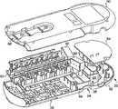
图1是依照本发明的一个实施方案的振荡抑制器的一个实施方案的透视图;Figure 1 is a perspective view of one embodiment of an oscillation suppressor according to one embodiment of the present invention;
图2是图1所示振荡抑制器的元器件的高级方框图;Figure 2 is a high level block diagram of the components of the oscillation suppressor shown in Figure 1;
图3A是图1所示振荡抑制器的底部分解透视图;Figure 3A is a bottom exploded perspective view of the oscillation suppressor shown in Figure 1;
图3B是依照本发明的振荡抑制器的替代实施方案的顶部分解透视图;Figure 3B is a top exploded perspective view of an alternate embodiment of an oscillation suppressor in accordance with the present invention;
图4是MOV和热熔断丝隔离结构的剖面图;Fig. 4 is a cross-sectional view of an MOV and a thermal fuse isolation structure;
图5是图1所示振荡抑制器的中间段(例如,数据段)的一个实施方案的透视图;Figure 5 is a perspective view of one embodiment of an intermediate segment (e.g., a data segment) of the oscillation suppressor shown in Figure 1;
图6是图1所示振荡抑制器底部的透视图;Figure 6 is a perspective view of the bottom of the oscillation suppressor shown in Figure 1;
图7是有脱离和远离振荡抑制器壳体的电缆管理器的图6所示振荡抑制器的底部透视图;7 is a bottom perspective view of the oscillation suppressor shown in FIG. 6 with the cable manager disengaged and remote from the oscillation suppressor housing;
图8是电源线处于第一位置时图1所示振荡抑制器的顶部透视图;Figure 8 is a top perspective view of the oscillation suppressor shown in Figure 1 with the power cord in the first position;
图9是电源线处在第二位置时图1所示振荡抑制器的顶部透视图;Figure 9 is a top perspective view of the oscillation suppressor shown in Figure 1 with the power cord in a second position;
图10是依照本发明的振荡抑制器的另一个实施方案的透视图;10 is a perspective view of another embodiment of an oscillation suppressor according to the present invention;
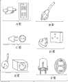
图11和图12举例说明与图1所示振荡抑制器共同使用的多种插头和/或插座;Figures 11 and 12 illustrate various plugs and/or sockets for use with the oscillation suppressor shown in Figure 1;
图13举例说明图1所示振荡抑制器的MOV、热熔断丝和隔离结构的一个实施方案;而Figure 13 illustrates one embodiment of the MOV, thermal fuse and isolation structure of the oscillation suppressor shown in Figure 1; and
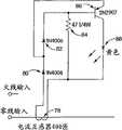
图14是过载检测/报警电路的示意图。Figure 14 is a schematic diagram of an overload detection/alarm circuit.
具体实施方式Detailed ways
本发明涉及振荡抑制器。参照图1,依照本发明的振荡抑制器20的一个实施方案有电源段22、毗连电源段的中间段24(例如,数据段)和毗连中间段的插座段26。振荡抑制器20有带表面25的壳体27而且能进一步包括与所述壳体可拆装地而且可复原地耦合的电缆管理器28。在一个实施方案中,使用者能调整电缆管理器28从壳体27伸出的程度。The present invention relates to oscillation suppressors. Referring to FIG. 1, one embodiment of a
电源段22有电源线30、主开关32、过载检测信号34和电路断路器复位按钮50。在一个实施方案中,中间段是数据段并且包括用于网络和/或电话线36和电缆接插件38的输入端。插座段包括三行插座,中心行42和外围两行40、44。外围两行40、44能包括适合接受变压器插头的变压器插座。因此,变压器插座的宽度应该至少是将要使用所述振荡抑制器的国家的标准插座的宽度的两倍。例如,在美国,标准插座是1.125英寸宽而变压器插座应该至少是2.25英寸宽。除此之外,如果壳体27的第一表面25实质上位于某个平面中,那么外围的插座46可以在所述平面之外向下倾斜,以使插拔中心行42的插头和/或插座变得容易。倾斜角度可以从大约5度到大约45度。在一个实施方案中,倾斜角度是大约10度。The
就本发明的目的而言,人们可以描述插座为带有顶边、底边、第一个侧边和第二个侧边的插座表面。另外,就本发明的目的而言,当第一插座表面48a的底边毗连第二插座表面48b的顶边的时候,人们可以把第一插座和第二插座描述成按上下次序排列。类似地,当第一插座表面46a的第一边毗连第二插座表面46b的第二边的时候,人们可以把第一插座和第二插座描述成按左右次序排列。如上所述,在一个实施方案中,中心行的插座是按上下次序排列的,而外围两行的插座是按左右次序排列的。For purposes of the present invention, one may describe a receptacle as a receptacle surface having a top side, a bottom side, a first side and a second side. Additionally, for purposes of the present invention, one may describe the first socket and the second socket as being in a top-down order when the bottom edge of the
参照图2,图1所示振荡抑制器的元器件包括交流电(ac)输入,例如,电源线,为印刷电路板(PCB)之上的电磁干扰(EMI)/振荡过滤器提供交流电。过滤器依次与过电流检测电路、火线和地面电气连接。过电流检测电路有对零线的电气连接。保护工作电路和现场配线故障电路有对火线、零线和地的电气连接。所述插座有对零线和地面的电气连接。常开插座有对火线的电气连接而开关插座已经把电气连接切换到火线。除此之外,振荡抑制器可以包括电话保护电路、电缆/数字客户服务(DSS)保护电路、电缆/天线保护电路和/或网络接口(例如,5类电缆标准接口)保护电路,上述电路中的每一个都有对地的电气连接。Referring to FIG. 2, components of the oscillation suppressor shown in FIG. 1 include an alternating current (ac) input, such as a power line, to provide AC power to an electromagnetic interference (EMI)/oscillation filter on a printed circuit board (PCB). The filter is electrically connected with the overcurrent detection circuit, the live wire and the ground in turn. The overcurrent detection circuit has an electrical connection to neutral. The protected working circuit and field wiring fault circuit have electrical connections to live, neutral and ground. The receptacle has electrical connections to neutral and ground. A normally open outlet has an electrical connection to the live wire while a switched outlet has the electrical connection switched to the live wire. In addition, the oscillation suppressor may include a telephone protection circuit, a cable/digital customer service (DSS) protection circuit, a cable/antenna protection circuit and/or a network interface (for example, a
参照图14,过载检测电路的一个实施方案包括与零线耦合的匝数比为400比1的变压器78。变压器的第一引线通过二极管80与pnp双极性晶体管86的发射极耦合。该发射极通过另一个二极管82与晶体管86的基极耦合。电阻把晶体管的基极接到变压器787的第二引线上。发光二极管(LED)88把晶体管86的集电极接到变压器78的第二引线上。通过选择大小适当的电阻,人们能选择使晶体管导通的基极电流。例如,人们选择检测电路的元器件以致在12安培下LED将开始发光,而且在15安培下LED将被完全照亮,在这个点它只是在电路断路器启动之前的时间问题。因此,过载检测电路提供渐近电路断路器启动点时的报警。Referring to FIG. 14, one embodiment of an overload detection circuit includes a
参照图3A,图1所示振荡抑制器包括第一和第二对置壳体部分52、50。在一个实施方案中,第一部分52是顶部半个壳体和第二部分50是底部半个壳体。振荡抑制器可以进一步包括按上下次序和按左右次序排列的插座组件60、包括金属氧化物变阻器(MOV)56和至少一条靠近MOV的热熔断丝的电源印刷电路板54、数据保护电路62、定义结构66的中间段和用来容纳MOV和热熔断丝的隔离结构64。Referring to FIG. 3A , the oscillation suppressor shown in FIG. 1 includes first and second opposed
如同能在图3A所示的分解图中见到的那样,在一个实施方案中,隔离结构64是与第一壳体部分52成为整体的隔断。该隔断将PCB密封以便用那至少一条热熔断丝封装MOV56。该隔断可以是大约0.035英寸到大约0.045英寸厚,以致如果引起MOV加热的过电压事件的话,该隔断向内坍塌,从而减少发射火和/或烟的可能。换句话说,隔离结构阻止在灾难性事件期间可能被排出的MOV形成的烟和碎片污染产品的其它部分。例如,隔离结构能阻止在PCB上形成能引起也被称为电阻性短路的传导性短路的碳痕。更明确地说,当振荡抑制器中的MOV出故障的时候,它能把碳分散在它所附着的板上,从而可能经由散布的碳造成电路板元件之间的不希望的电传导。As can be seen in the exploded view shown in FIG. 3A , in one embodiment, the
除此之外,隔离结构使从MOV到热熔断丝的热传递变得容易,以保证热熔断丝在可能过度损害MOV的严重热失控之前清除。更明确地说,并且参照图1、图3A和图13,隔离结构64把MOV56产生的热量截留在由隔离结构和第一和第二壳体部分定义的相对较小的体积之内。以这种方式,隔离结构使从MOV到位置靠近MOV(例如,夹在两个或多个MOV之间)的热熔断丝63的热传递变得容易。In addition, the isolation structure facilitates heat transfer from the MOV to the thermal link to ensure that the thermal link clears before severe thermal runaway that could excessively damage the MOV. More specifically, and with reference to FIGS. 1, 3A and 13,
如同也能在图3A中见到的那样,在一个实施方案中,定义结构66的中间段是与第一壳体部分52成为整体的隔断。隔断66提供进一步防止在灾难性事件期间可能出现的烟、热和碎片损坏产品的其它部分的保护。隔断66还确保在数据段24中来自灾难性事件的碎片和烟不污染插座段26。As can also be seen in FIG. 3A , in one embodiment, the intermediate
参照图1、图3A、图6和图7,第二壳体部分50也能包括电缆管理器接合槽58,该接合槽用于与电缆管理器28可滑动地和可调地接合。更明确地说,在一个实施方案中,接合槽58可以包括适合与电缆管理器接合并且有利于滑动的夹持脊68、使用者调整的电缆管理器的延伸部分远离壳体27。此外,如图7所示,人们能把电缆管理器28从壳体27中完全移出并且用安装孔70把电缆管理器28安装到外部位置。如图3B所示,在一个实施方案中,电缆管理器包括剑舌25(适合插入接合槽58的)和两个彼此向对方卷曲的臂23a、23b,以致臂的末端(即手状物)几乎相碰。这种结构允许电缆管理器可调整地从振荡抑制器壳体中伸出并且接受多个能插进振荡抑制器的电源线、电缆和/或数据线。参照图3A和图3B,剑舌25和/或接合槽58可以包括棘爪51、53,以允许电缆管理器移动到伸出位置,以致棘爪阻止电缆管理器任意地运动/伸缩。Referring to FIGS. 1 , 3A , 6 and 7 , the
参照图3B和图10,依照本发明的振荡抑制器20的替代实施方案总共有八个插座,包括三个中心插座和外围两行的每行两个外围插座。图3B还清楚地展示振荡抑制器的MOV56。参照图1、图3B、图5、图8和图9,振荡抑制器进一步包括能在电源线30和壳体27之间的接触点围绕着垂直于该表面的轴线旋转180度的电源线30。与电源线耦合的应变消除33安装在电源线滞留元件35中以将电源线30固定到壳体27上。应变消除包括与在较低的壳体部分50上对应的限制旋转元件接触的限制旋转元件37。通过限制电源线旋转,依照本发明的振荡抑制器的实施方案有利于电缆的运动避开装置的用户接口的障碍,同时防止电源线被扭曲远离它所连接的PCB。因此,图8展示旋转电源线处在第一位置,而图9展示从第一位置旋转180度到第二位置的旋转电源线。Referring to Figures 3B and 10, an alternative embodiment of a ringing
参照图1和图4,在一个实施方案中,隔离结构64能采取装有多个的MOV56和至少一条热熔断丝的L形围栏形式。列举的围栏位于主开关32和中间段24之间。参照图1和图5,如上所述,振荡抑制器可以进一步包括中间段限定(ISD)结构66。如图所示,ISD结构66可以采取实质上提供360度物理隔离把数据元件与振荡抑制器的其它部分隔开的隔断66的形式。换句话说,在与壳体的第一和第二部分50、52的组合中,隔断66实质上能封装振荡抑制器的数据元件以保护振荡抑制器的其它部分使之免受由于灾难性事件可能在数据段中出现的任何烟雾和/或碎片的损害。Referring to Figures 1 and 4, in one embodiment,
参照图1、图11和图12,振荡抑制器可以包括多种插座类型,其中包括:用来适应扁平插脚插头的A型插座;用来适应有扁平插脚和圆形接地插脚的插头的B型插座;用来适应有圆形插脚的插头的C型插座;用来适应圆形插脚和接地插脚按等边三角形排列的插头的D型插座;用来适应有圆形插脚和接地插孔的插头的E型插座;Schuko插座;用来适应有矩形插脚的插头的G型插座;用来适应斜的扁平插脚和接地插脚按Y形配置的插头的H型插座;用来适应斜的扁平插脚和接地插脚按箭头形配置的插头的I型插座;用来适应圆形插脚和接地插脚按等腰三角形排列的插头的J型插座;用来适应有圆形插脚和非圆形接地插脚的插头的K型插座;和用来适应圆形插脚和圆形接地插脚排成一列的插头的L型插座。此外,用于本发明的多用途插座包括电力输出端,而且可以包括与多用途插座成为整体的防触电挡板。防触电挡板要求电源插头的两个插脚用相等的力形成接触才能接触多用途插座的电力输出端。Referring to Figures 1, 11 and 12, ring suppressors can include a variety of receptacle types including: Type A receptacles to accommodate flat prong plugs; Type B receptacles to accommodate plugs with flat prongs and round ground prongs Receptacles; type C sockets to accommodate plugs having round prongs; type D sockets to accommodate plugs having round prongs and grounding prongs arranged in an equilateral triangle; type D sockets to accommodate plugs having round prongs and grounding sockets Type E receptacle; Schuko receptacle; G receptacle to accommodate plugs with rectangular prongs; H receptacle to accommodate plugs with slanted flat prongs and grounding prongs arranged in a Y configuration; Type I socket-outlet for plugs with an arrow-shaped arrangement of grounding pins; J-type socket-outlet for plugs with round and grounding pins arranged in an isosceles triangle; for plugs with round and non-circular grounding pins Type K receptacles; and L-shaped receptacles to accommodate plugs with round prongs and round grounding prongs aligned in a row. In addition, the multi-purpose outlet used in the present invention includes a power outlet, and may include an electric shock-proof shield integral with the multi-purpose outlet. The anti-shock barrier requires that the two prongs of the power plug make contact with equal force to contact the power output of the multi-purpose socket.
至此已描述了本发明的至少一个说明性的实施方案,各种不同的替代方案、修改方案和改进方案已在本发明的考虑范围内,包括下列各项。振荡抑制器可以有三行以上或以下插座。例如,依照本发明的振荡抑制器可以有两行中心插座或只有外围两行而没有中心行。为了详细解释这一点,出于安全原因,在英国,电缆相对于插头的插脚以直角延伸出来,以致使用者不能通过用力拉电缆而把插头从插座中拔出。因此,就振荡抑制器而言,对于英国意味着有按上下次序排列的插座的中心行可能是不切实际的,而只有外围两行的振荡抑制器可能更适合。此外,本发明除了分开提供MOV和热熔断丝的实施方案之外还考虑整体式热熔断丝的MOV的使用。除此之外,对技术上已知的电缆管理器的各种不同的修改方案也在本发明的考虑范围内。例如,用来把电缆管理器与振荡抑制器的壳体接合的装置可能包括与扁平的剑舌对立的轴。这样的替代方案、修改方案和改进方案倾向于在本发明的范围之内并符合本发明的主旨。因此,前面的描述仅仅是举例说明并不倾向于作为限制。本发明的限制是仅仅在权利要求书及其等价文件中定义的。Having thus described at least one illustrative embodiment of the invention, various alternatives, modifications and improvements are contemplated within the scope of the invention, including the following. Ring suppressors can have more or less than three rows of sockets. For example, a ringing suppressor according to the present invention may have two central rows of sockets or only the outer two rows and no central row. To explain this in detail, for safety reasons in the UK the cable runs out at right angles to the prongs of the plug so that the user cannot pull the plug out of the socket by pulling on the cable. So in terms of ring dampers, it might be impractical for the UK to mean that there is a central row of sockets in order up and down, whereas a ring damper with only the outer two rows might be more suitable. Furthermore, the present invention contemplates the use of MOVs with integral thermal links in addition to embodiments where the MOV and thermal link are provided separately. Apart from this, various modifications of the cable managers known in the art are also within the scope of the invention. For example, the means for engaging the cable manager with the housing of the vibration suppressor may include a shaft opposed to a flat sword tongue. Such alternatives, modifications and improvements are intended to be within the scope and spirit of the invention. Accordingly, the foregoing description is by way of illustration only and is not intended to be limiting. The limitations of the invention are defined only in the claims and their equivalents.
Claims (15)
Translated fromChineseApplications Claiming Priority (2)
| Application Number | Priority Date | Filing Date | Title |
|---|---|---|---|
| US10/411,493US7193830B2 (en) | 2003-04-10 | 2003-04-10 | Surge suppressor |
| US10/411,493 | 2003-04-10 |
Publications (2)
| Publication Number | Publication Date |
|---|---|
| CN1788399A CN1788399A (en) | 2006-06-14 |
| CN100576684Ctrue CN100576684C (en) | 2009-12-30 |
Family
ID=33130998
Family Applications (1)
| Application Number | Title | Priority Date | Filing Date |
|---|---|---|---|
| CN200480012743AExpired - Fee RelatedCN100576684C (en) | 2003-04-10 | 2004-04-09 | Oscillation suppressor |
Country Status (5)
| Country | Link |
|---|---|
| US (1) | US7193830B2 (en) |
| CN (1) | CN100576684C (en) |
| DE (1) | DE112004000615T5 (en) |
| GB (1) | GB2416253B (en) |
| WO (1) | WO2004093282A2 (en) |
Families Citing this family (36)
| Publication number | Priority date | Publication date | Assignee | Title |
|---|---|---|---|---|
| US6971920B2 (en)* | 2004-04-26 | 2005-12-06 | Crupi Theodore P | Electrical multiple outlet device and electrical device having pivotable electrical prongs |
| US7347724B2 (en)* | 2004-12-16 | 2008-03-25 | Theodore P Crupi | Electrical multiple receptacle outlet |
| US7274975B2 (en) | 2005-06-06 | 2007-09-25 | Gridpoint, Inc. | Optimized energy management system |
| WO2007010270A1 (en)* | 2005-07-21 | 2007-01-25 | Carl Attenborough | Modular outdoor electrical supply and distribution system |
| US7460348B2 (en)* | 2005-09-06 | 2008-12-02 | Filippenko Alexander S | Overload detector/enunciator |
| US7361050B2 (en)* | 2005-11-17 | 2008-04-22 | Belkin International, Inc. | Cable management device for use in connection with a power center, and cable management system comprising same |
| AU2006252237C1 (en)* | 2006-01-06 | 2009-11-12 | Belkin International, Inc. | Surge suppressor, electronic device, and method with components oriented for improved safety |
| US7675739B2 (en)* | 2006-01-11 | 2010-03-09 | Server Technology, Inc. | Fuse module with removable fuse carrier for fused electrical device |
| US7447002B2 (en)* | 2006-01-11 | 2008-11-04 | Server Technology, Inc. | Fuse module with movable fuse holder for fused electrical device |
| WO2007082071A2 (en)* | 2006-01-11 | 2007-07-19 | Server Technology, Inc. | Power distribution unit and methods of making and use including modular construction and assemblies |
| US8103389B2 (en) | 2006-05-18 | 2012-01-24 | Gridpoint, Inc. | Modular energy control system |
| US7874410B2 (en)* | 2006-11-16 | 2011-01-25 | Fulbrook Jason D | Intravenous pole power organizer (IVPPO) |
| US8283802B2 (en) | 2009-06-11 | 2012-10-09 | American Power Conversion Corporation | Dual column gang outlets for minimizing installation space |
| US7824196B1 (en) | 2009-07-17 | 2010-11-02 | Hubbell Incorporated | Multiple outlet electrical receptacle |
| US8734181B1 (en)* | 2010-12-04 | 2014-05-27 | Kevin Waggoner | Electrical outlet cover with excess cord storage |
| USD701834S1 (en)* | 2011-09-29 | 2014-04-01 | Monster Cable Products, Inc. | Power strip |
| USD705732S1 (en)* | 2011-09-29 | 2014-05-27 | Monster Cable Products, Inc. | Power Strip |
| US8439692B1 (en)* | 2011-11-01 | 2013-05-14 | Hubbell Incorporated | Bus bar arrangements for multiple outlet electrical receptacles |
| USD838671S1 (en)* | 2018-08-01 | 2019-01-22 | Da Vinci Ii Csj Llc | Rotating electrical fixture |
| DE202018107182U1 (en)* | 2018-12-14 | 2020-03-19 | INDU-ELECTRIC Gerber GmbH | Overvoltage protection |
| USD904983S1 (en)* | 2020-07-07 | 2020-12-15 | Chizhou Andaxing Electronics Technology Co., Ltd | Power strip |
| USD924808S1 (en)* | 2020-11-05 | 2021-07-13 | Chizhou Qinglianfeng Electronics Technology Co., Ltd | Power strip |
| USD924807S1 (en)* | 2020-11-05 | 2021-07-13 | Chizhou Qinglianfeng Electronics Technology Co., Ltd | Power strip |
| USD922954S1 (en)* | 2020-11-12 | 2021-06-22 | Jurong Shudaan Electronics Technology Co., Ltd | Power strip |
| USD924809S1 (en)* | 2020-11-12 | 2021-07-13 | Chizhou Andaxing Electronics Technology Co., Ltd | Power strip |
| USD922953S1 (en)* | 2020-11-12 | 2021-06-22 | Jurong Shudaan Electronics Technology Co., Ltd | Power strip |
| USD931220S1 (en)* | 2020-11-19 | 2021-09-21 | Guiming WANG | Power strip |
| USD922955S1 (en)* | 2021-01-11 | 2021-06-22 | Chizhou Fengpu Electronics Technology Co., Ltd | Power strip |
| USD922956S1 (en)* | 2021-01-11 | 2021-06-22 | Shenzhen Mingrui Industrial Co., Ltd | Extension socket |
| USD977429S1 (en)* | 2021-08-05 | 2023-02-07 | Jasco Products Company LLC | Surge protector |
| USD1062640S1 (en)* | 2021-12-06 | 2025-02-18 | Jasco Products Company LLC | Surge protector |
| USD1004553S1 (en)* | 2022-04-20 | 2023-11-14 | Guangzhou Tai Rong Yi Technology Co., Ltd. | Socket |
| USD1017548S1 (en)* | 2022-08-15 | 2024-03-12 | Lg-Led Solutions Limited | Power distribution unit |
| USD1003251S1 (en)* | 2023-07-14 | 2023-10-31 | Xusheng Chen | Power strip |
| USD1041423S1 (en)* | 2024-03-25 | 2024-09-10 | Jiande Hunlee Electrical Appliance Co., Ltd | Wiring board |
| USD1041422S1 (en)* | 2024-03-25 | 2024-09-10 | Jiande Hunlee Electrical Appliance Co., Ltd | Wiring board |
Family Cites Families (44)
| Publication number | Priority date | Publication date | Assignee | Title |
|---|---|---|---|---|
| US433386A (en)* | 1890-07-29 | Road-cart | ||
| US342055A (en)* | 1886-05-18 | Slide-valve | ||
| US350940A (en)* | 1886-10-19 | Tack-pulling and sole-trimming machine for boots or shoes | ||
| US445403A (en)* | 1891-01-27 | Andrew b | ||
| US411981A (en)* | 1889-10-01 | Method of cementing cisterns or wells | ||
| US458225A (en)* | 1891-08-25 | Frederick d | ||
| US468366A (en)* | 1892-02-09 | George hand smith | ||
| US368893A (en)* | 1887-08-23 | Lottis lo wenthal | ||
| US363059A (en)* | 1887-05-17 | Feedeeick w | ||
| US439562A (en)* | 1890-10-28 | Gun-carrier | ||
| US467875A (en)* | 1892-01-26 | Adam lungen | ||
| US416234A (en)* | 1889-12-03 | Edward s | ||
| USD284758S (en)* | 1983-04-25 | 1986-07-22 | International Jensen Incorporated | Power outlet box with integral surge protector |
| US4930047A (en)* | 1988-09-12 | 1990-05-29 | The Toro Company | Apparatus for interconnecting components of a power outlet strip |
| USD319213S (en)* | 1989-02-01 | 1991-08-20 | Wiand Richard K | Electrical outlet strip |
| US5071367A (en)* | 1989-10-06 | 1991-12-10 | Pacomex Industries, Inc. | Power strip with adjustable cord |
| USD342055S (en) | 1991-11-01 | 1993-12-07 | American Power Conversion Corporation | Housing for a surge suppressor |
| USD350940S (en) | 1993-03-12 | 1994-09-27 | Curtis Manufacturing Company, Inc. | Multiple outlet surge protector with cable management |
| US5488534A (en)* | 1993-08-19 | 1996-01-30 | Emerson Electric Co. | Transient voltage surge suppression module with ultrafast fusing |
| USD363059S (en) | 1994-05-31 | 1995-10-10 | American Power Conversion Corporation | Housing for electrical power surge protector |
| USD368893S (en)* | 1994-09-15 | 1996-04-16 | Harwood George E | Power tap outlet strip |
| US5519561A (en)* | 1994-11-08 | 1996-05-21 | Eaton Corporation | Circuit breaker using bimetal of thermal-magnetic trip to sense current |
| US5708554A (en)* | 1996-03-12 | 1998-01-13 | Liner; Leonard | Power outlet box with special protection logic |
| US6042426A (en)* | 1996-11-13 | 2000-03-28 | Byrne; Norman R. | Multi-user electrical services outlet |
| US5780775A (en)* | 1997-03-20 | 1998-07-14 | Yu; Tsung-I | Power strip with inspection window |
| US5902140A (en)* | 1997-10-01 | 1999-05-11 | Recoton Corporation | Child-safe power strip |
| USD411981S (en) | 1997-11-14 | 1999-07-13 | American Power Conversion Corporation | Electrical surge protector unit for desk top products |
| US6179665B1 (en)* | 1998-08-27 | 2001-01-30 | Curtis Computer Products, Inc. | Multi-function outlet strip having cable organizing features |
| USD411168S (en)* | 1998-08-27 | 1999-06-22 | Rossman Jon R | Power strip |
| US6188557B1 (en)* | 1998-11-23 | 2001-02-13 | Tii Industries, Inc. | Surge suppressor |
| USD416234S (en) | 1998-11-24 | 1999-11-09 | American Power Conversion Corporation | Portion of an electrical surge protector |
| USD433386S (en) | 1999-01-21 | 2000-11-07 | American Power Conversion Corporation | Transient voltage surge suppressor |
| US6282075B1 (en)* | 1999-03-10 | 2001-08-28 | Tii Industries, Inc. | Surge suppressor with virtual ground |
| US6113434A (en)* | 1999-03-25 | 2000-09-05 | Pate; D. Frank | Outlet for accepting multiple enlarged plugs |
| USD439562S1 (en) | 2000-02-22 | 2001-03-27 | American Power Conversion Corporation | Surge protector |
| USD435516S (en)* | 2000-05-17 | 2000-12-26 | All Line, Inc. | Power strip |
| USD445091S1 (en)* | 2000-06-06 | 2001-07-17 | Belkin Components | Multiple outlet surge strip |
| USD455091S1 (en)* | 2000-10-26 | 2002-04-02 | Toshiba Tec Kabushiki Kaisha | Electronic scale with printer |
| US6816352B2 (en)* | 2001-02-16 | 2004-11-09 | Panamax | Abnormal voltage protection circuit |
| US6443772B1 (en)* | 2001-06-26 | 2002-09-03 | Hong Gy Co., Ltd. | Common two-prong and three-prong socket AC power receptacle |
| USD458225S1 (en)* | 2001-09-24 | 2002-06-04 | All-Line Inc. | Power strip |
| USD467875S1 (en) | 2001-11-19 | 2002-12-31 | Stratitec | Surge protector |
| USD468366S1 (en) | 2002-01-09 | 2003-01-07 | American Power Conversion Corporation | Video game management system with surge protection |
| US6971920B2 (en)* | 2004-04-26 | 2005-12-06 | Crupi Theodore P | Electrical multiple outlet device and electrical device having pivotable electrical prongs |
- 2003
- 2003-04-10USUS10/411,493patent/US7193830B2/ennot_activeExpired - Fee Related
- 2004
- 2004-04-09GBGB0520766Apatent/GB2416253B/ennot_activeExpired - Fee Related
- 2004-04-09DEDE112004000615Tpatent/DE112004000615T5/ennot_activeWithdrawn
- 2004-04-09CNCN200480012743Apatent/CN100576684C/ennot_activeExpired - Fee Related
- 2004-04-09WOPCT/US2004/010926patent/WO2004093282A2/enactiveApplication Filing
Also Published As
| Publication number | Publication date |
|---|---|
| WO2004093282A2 (en) | 2004-10-28 |
| US20040201940A1 (en) | 2004-10-14 |
| CN1788399A (en) | 2006-06-14 |
| US7193830B2 (en) | 2007-03-20 |
| GB0520766D0 (en) | 2005-11-23 |
| WO2004093282A3 (en) | 2005-08-11 |
| DE112004000615T5 (en) | 2006-03-09 |
| GB2416253B (en) | 2007-04-18 |
| GB2416253A (en) | 2006-01-18 |
Similar Documents
| Publication | Publication Date | Title |
|---|---|---|
| CN100576684C (en) | Oscillation suppressor | |
| US5642248A (en) | Electrical extension cord with built-in safety protection | |
| US4191985A (en) | Interrupter | |
| US5902140A (en) | Child-safe power strip | |
| CN100442609C (en) | Power Line Regulator with Voltage and Current Magnitude Tracking | |
| US6179665B1 (en) | Multi-function outlet strip having cable organizing features | |
| US8152570B2 (en) | Power connector having protective interior cover | |
| US20050185354A1 (en) | Protection of A/V components | |
| US7887363B1 (en) | Protective electrical wiring device and system | |
| US20040246644A1 (en) | Surge protector assembly with ground-connected status indicator circuitry | |
| US5006950A (en) | Electrical transient surge protection with parallel means | |
| US5748424A (en) | Electrical plug receptacle | |
| US5761021A (en) | Voltage surge suppression device | |
| CN106654735A (en) | Connector with a locking member | |
| JP2010034049A (en) | Blanking plug for communication jack | |
| CA2732360C (en) | Surge snap-on module assembly | |
| JPH11510950A (en) | Transient voltage surge protection assembly for communication lines | |
| US4901187A (en) | Electrical transient surge protection | |
| CN101986399B (en) | Overvoltage protection element | |
| US5917391A (en) | Transient voltage surge suppressor having a switch with overtravel protection | |
| US8215993B2 (en) | Socket | |
| US7271991B2 (en) | Protection circuit for signal and power | |
| US10014639B1 (en) | Electrical receptacle | |
| CN202206074U (en) | Protective electrical wiring device | |
| US5923517A (en) | Transient voltage surge suppressor with a reversible on-off switch assembly |
Legal Events
| Date | Code | Title | Description |
|---|---|---|---|
| C06 | Publication | ||
| PB01 | Publication | ||
| C10 | Entry into substantive examination | ||
| SE01 | Entry into force of request for substantive examination | ||
| C14 | Grant of patent or utility model | ||
| GR01 | Patent grant | ||
| CF01 | Termination of patent right due to non-payment of annual fee | Granted publication date:20091230 Termination date:20180409 | |
| CF01 | Termination of patent right due to non-payment of annual fee |