CN100574819C - Pivotable injection needle unit - Google Patents
Pivotable injection needle unitDownload PDFInfo
- Publication number
- CN100574819C CN100574819CCN200480012437ACN200480012437ACN100574819CCN 100574819 CCN100574819 CCN 100574819CCN 200480012437 ACN200480012437 ACN 200480012437ACN 200480012437 ACN200480012437 ACN 200480012437ACN 100574819 CCN100574819 CCN 100574819C
- Authority
- CN
- China
- Prior art keywords
- needle
- percutaneous
- housing
- percutaneous device
- reservoir
- Prior art date
- Legal status (The legal status is an assumption and is not a legal conclusion. Google has not performed a legal analysis and makes no representation as to the accuracy of the status listed.)
- Expired - Fee Related
Links
- 238000002347injectionMethods0.000titleclaimsdescription52
- 239000007924injectionSubstances0.000titleclaimsdescription52
- 238000003780insertionMethods0.000claimsabstractdescription51
- 230000037431insertionEffects0.000claimsabstractdescription51
- 239000003814drugSubstances0.000claimsdescription39
- 239000007788liquidSubstances0.000claimsdescription24
- 239000012530fluidSubstances0.000claimsdescription22
- 238000004891communicationMethods0.000claimsdescription13
- 230000008878couplingEffects0.000claimsdescription5
- 238000010168coupling processMethods0.000claimsdescription5
- 238000005859coupling reactionMethods0.000claimsdescription5
- 238000006073displacement reactionMethods0.000claimsdescription5
- 238000005086pumpingMethods0.000claimsdescription2
- 238000009434installationMethods0.000claims1
- 238000012377drug deliveryMethods0.000abstractdescription5
- 238000003860storageMethods0.000description11
- NOESYZHRGYRDHS-UHFFFAOYSA-NinsulinChemical compoundN1C(=O)C(NC(=O)C(CCC(N)=O)NC(=O)C(CCC(O)=O)NC(=O)C(C(C)C)NC(=O)C(NC(=O)CN)C(C)CC)CSSCC(C(NC(CO)C(=O)NC(CC(C)C)C(=O)NC(CC=2C=CC(O)=CC=2)C(=O)NC(CCC(N)=O)C(=O)NC(CC(C)C)C(=O)NC(CCC(O)=O)C(=O)NC(CC(N)=O)C(=O)NC(CC=2C=CC(O)=CC=2)C(=O)NC(CSSCC(NC(=O)C(C(C)C)NC(=O)C(CC(C)C)NC(=O)C(CC=2C=CC(O)=CC=2)NC(=O)C(CC(C)C)NC(=O)C(C)NC(=O)C(CCC(O)=O)NC(=O)C(C(C)C)NC(=O)C(CC(C)C)NC(=O)C(CC=2NC=NC=2)NC(=O)C(CO)NC(=O)CNC2=O)C(=O)NCC(=O)NC(CCC(O)=O)C(=O)NC(CCCNC(N)=N)C(=O)NCC(=O)NC(CC=3C=CC=CC=3)C(=O)NC(CC=3C=CC=CC=3)C(=O)NC(CC=3C=CC(O)=CC=3)C(=O)NC(C(C)O)C(=O)N3C(CCC3)C(=O)NC(CCCCN)C(=O)NC(C)C(O)=O)C(=O)NC(CC(N)=O)C(O)=O)=O)NC(=O)C(C(C)CC)NC(=O)C(CO)NC(=O)C(C(C)O)NC(=O)C1CSSCC2NC(=O)C(CC(C)C)NC(=O)C(NC(=O)C(CCC(N)=O)NC(=O)C(CC(N)=O)NC(=O)C(NC(=O)C(N)CC=1C=CC=CC=1)C(C)C)CC1=CN=CN1NOESYZHRGYRDHS-UHFFFAOYSA-N0.000description10
- 229940079593drugDrugs0.000description9
- 230000009471actionEffects0.000description6
- 102000004877InsulinHuman genes0.000description5
- 108090001061InsulinProteins0.000description5
- 238000001802infusionMethods0.000description5
- 229940125396insulinDrugs0.000description5
- 239000012528membraneSubstances0.000description5
- 230000004913activationEffects0.000description4
- 239000000853adhesiveSubstances0.000description4
- 230000001070adhesive effectEffects0.000description4
- 239000002184metalSubstances0.000description4
- 238000000034methodMethods0.000description3
- 230000003204osmotic effectEffects0.000description3
- 238000007920subcutaneous administrationMethods0.000description3
- 230000003213activating effectEffects0.000description2
- 230000015572biosynthetic processEffects0.000description2
- 238000005755formation reactionMethods0.000description2
- 230000000149penetrating effectEffects0.000description2
- 230000002040relaxant effectEffects0.000description2
- 239000000243solutionSubstances0.000description2
- 238000011282treatmentMethods0.000description2
- XLYOFNOQVPJJNP-UHFFFAOYSA-NwaterSubstancesOXLYOFNOQVPJJNP-UHFFFAOYSA-N0.000description2
- 238000003466weldingMethods0.000description2
- 108010075254C-PeptideProteins0.000description1
- 241001631457CannulaSpecies0.000description1
- 101710190529Insulin-like peptideProteins0.000description1
- FAPWRFPIFSIZLT-UHFFFAOYSA-MSodium chlorideChemical compound[Na+].[Cl-]FAPWRFPIFSIZLT-UHFFFAOYSA-M0.000description1
- 229910000831SteelInorganic materials0.000description1
- 239000004809TeflonSubstances0.000description1
- 229920006362Teflon®Polymers0.000description1
- 230000003187abdominal effectEffects0.000description1
- 239000013543active substanceSubstances0.000description1
- 238000004026adhesive bondingMethods0.000description1
- 230000000712assemblyEffects0.000description1
- 238000000429assemblyMethods0.000description1
- 230000004888barrier functionEffects0.000description1
- 238000005452bendingMethods0.000description1
- 239000003124biologic agentSubstances0.000description1
- 239000003795chemical substances by applicationSubstances0.000description1
- 239000002131composite materialSubstances0.000description1
- 238000012938design processMethods0.000description1
- 206010012601diabetes mellitusDiseases0.000description1
- 238000010586diagramMethods0.000description1
- 230000037213dietEffects0.000description1
- 235000005911dietNutrition0.000description1
- 238000007599dischargingMethods0.000description1
- 239000000499gelSubstances0.000description1
- 230000002068genetic effectEffects0.000description1
- 238000010438heat treatmentMethods0.000description1
- 230000003054hormonal effectEffects0.000description1
- 229940088597hormoneDrugs0.000description1
- 239000005556hormoneSubstances0.000description1
- 230000002608insulinlikeEffects0.000description1
- 238000007918intramuscular administrationMethods0.000description1
- 238000001990intravenous administrationMethods0.000description1
- 238000004519manufacturing processMethods0.000description1
- 239000000463materialSubstances0.000description1
- 230000007246mechanismEffects0.000description1
- 229940127554medical productDrugs0.000description1
- 229910001092metal group alloyInorganic materials0.000description1
- 235000016709nutritionNutrition0.000description1
- 230000002093peripheral effectEffects0.000description1
- 229920000642polymerPolymers0.000description1
- 238000003825pressingMethods0.000description1
- 230000008569processEffects0.000description1
- 102000004196processed proteins & peptidesHuman genes0.000description1
- 108090000765processed proteins & peptidesProteins0.000description1
- 230000001681protective effectEffects0.000description1
- 102000004169proteins and genesHuman genes0.000description1
- 108090000623proteins and genesProteins0.000description1
- 238000007789sealingMethods0.000description1
- 239000007787solidSubstances0.000description1
- 125000006850spacer groupChemical group0.000description1
- 239000010935stainless steelSubstances0.000description1
- 229910001220stainless steelInorganic materials0.000description1
- 239000010959steelSubstances0.000description1
- 239000000126substanceSubstances0.000description1
Images


Classifications
- A—HUMAN NECESSITIES
- A61—MEDICAL OR VETERINARY SCIENCE; HYGIENE
- A61M—DEVICES FOR INTRODUCING MEDIA INTO, OR ONTO, THE BODY; DEVICES FOR TRANSDUCING BODY MEDIA OR FOR TAKING MEDIA FROM THE BODY; DEVICES FOR PRODUCING OR ENDING SLEEP OR STUPOR
- A61M5/00—Devices for bringing media into the body in a subcutaneous, intra-vascular or intramuscular way; Accessories therefor, e.g. filling or cleaning devices, arm-rests
- A61M5/14—Infusion devices, e.g. infusing by gravity; Blood infusion; Accessories therefor
- A61M5/158—Needles for infusions; Accessories therefor, e.g. for inserting infusion needles, or for holding them on the body
- A—HUMAN NECESSITIES
- A61—MEDICAL OR VETERINARY SCIENCE; HYGIENE
- A61B—DIAGNOSIS; SURGERY; IDENTIFICATION
- A61B5/00—Measuring for diagnostic purposes; Identification of persons
- A61B5/68—Arrangements of detecting, measuring or recording means, e.g. sensors, in relation to patient
- A61B5/6846—Arrangements of detecting, measuring or recording means, e.g. sensors, in relation to patient specially adapted to be brought in contact with an internal body part, i.e. invasive
- A61B5/6847—Arrangements of detecting, measuring or recording means, e.g. sensors, in relation to patient specially adapted to be brought in contact with an internal body part, i.e. invasive mounted on an invasive device
- A61B5/6848—Needles
- A61B5/6849—Needles in combination with a needle set
- A—HUMAN NECESSITIES
- A61—MEDICAL OR VETERINARY SCIENCE; HYGIENE
- A61M—DEVICES FOR INTRODUCING MEDIA INTO, OR ONTO, THE BODY; DEVICES FOR TRANSDUCING BODY MEDIA OR FOR TAKING MEDIA FROM THE BODY; DEVICES FOR PRODUCING OR ENDING SLEEP OR STUPOR
- A61M5/00—Devices for bringing media into the body in a subcutaneous, intra-vascular or intramuscular way; Accessories therefor, e.g. filling or cleaning devices, arm-rests
- A61M5/14—Infusion devices, e.g. infusing by gravity; Blood infusion; Accessories therefor
- A61M5/142—Pressure infusion, e.g. using pumps
- A61M5/14244—Pressure infusion, e.g. using pumps adapted to be carried by the patient, e.g. portable on the body
- A61M5/14248—Pressure infusion, e.g. using pumps adapted to be carried by the patient, e.g. portable on the body of the skin patch type
- A61M2005/14252—Pressure infusion, e.g. using pumps adapted to be carried by the patient, e.g. portable on the body of the skin patch type with needle insertion means
Landscapes
- Health & Medical Sciences (AREA)
- Life Sciences & Earth Sciences (AREA)
- Public Health (AREA)
- Veterinary Medicine (AREA)
- Biomedical Technology (AREA)
- Heart & Thoracic Surgery (AREA)
- General Health & Medical Sciences (AREA)
- Engineering & Computer Science (AREA)
- Animal Behavior & Ethology (AREA)
- Hematology (AREA)
- Vascular Medicine (AREA)
- Anesthesiology (AREA)
- Physics & Mathematics (AREA)
- Biophysics (AREA)
- Pathology (AREA)
- Medical Informatics (AREA)
- Molecular Biology (AREA)
- Surgery (AREA)
- Dermatology (AREA)
- Infusion, Injection, And Reservoir Apparatuses (AREA)
- Fuel-Injection Apparatus (AREA)
Abstract
Translated fromChineseDescription
Translated fromChinese技术领域technical field
本发明总体上涉及诸如针头、针状件和插管之类的经皮器械的插入。更加具体地讲,本发明涉及经皮器械在患者体内的选定部位上的插入,用于将药剂以皮下、静脉、肌肉或皮内方式输送给患者,该经皮器械由适于贴敷到患者皮肤上的器械携带。尤其是,本发明涉及穿过患者的皮肤的用于注射药剂的注射针头或插管的插入、针头形传感器的插入以及用于诸如传感器之类的器械的方便放置的插入针头的插入。The present invention generally relates to the insertion of percutaneous devices such as needles, needles and cannulas. More particularly, the present invention relates to the insertion of a percutaneous device at a selected site in a patient's body for the subcutaneous, intravenous, intramuscular or intradermal delivery of a medicament to the patient, the percutaneous device being adapted to be applied to The device is carried on the patient's skin. In particular, the present invention relates to the insertion of an injection needle or cannula for injecting a medicament through the skin of a patient, insertion of a needle-shaped sensor, and insertion of an insertion needle for convenient placement of an instrument such as a sensor.
背景技术Background technique
在本发明的公开文本中,主要对通过注入或注射胰岛素进行的糖尿病治疗进行了参考,不过,这仅仅是本发明的示范性用途。In the present disclosure, reference is mainly made to the treatment of diabetes by infusion or injection of insulin, however, this is only an exemplary use of the present invention.
用于向患者输送药剂的便携式药剂输送器械是众所周知的,并且通常包括一个储液罐(reservoir)以及排出装置,该储液罐用于容纳液体药品并且具有一个与一中空注射针头进行流通的出口,该排出装置用于将药剂排出该储液罐并经由该中空针头而通过患者的皮肤。这种器械常被称作注射泵。Portable drug delivery devices for delivering drug to a patient are well known and generally include a reservoir for containing liquid drug and having an outlet in communication with a hollow injection needle, and discharge means , the discharge device is used to discharge the medicament from the liquid storage tank and pass through the patient's skin via the hollow needle. Such devices are often referred to as syringe pumps.
注射泵大体可分成两种类型。第一种类型是耐用型注射泵,这是可使用3-4年的相对较昂贵的注射泵,由此,这种泵的最初成本常常是此类治疗方法的障碍。尽管相比于传统的注射器或注射笔,这种泵更加复杂,但它具有下列优点:连续的胰岛素注射、剂量精确、可任意编程的输送规格以及与饮食相关联的使用者进行的快速注射。Syringe pumps can be broadly divided into two types. The first type is the durable syringe pump, which is a relatively expensive syringe pump that lasts 3-4 years, whereby the initial cost of such a pump is often a barrier to such treatments. Although more complex than conventional syringes or pens, this pump offers the following advantages: continuous insulin injection, dosing accuracy, arbitrarily programmable delivery specifications, and bolus injection for users associated with diet.
针对上述问题,已经进行了多种尝试来提供成本低廉且便于使用的第二类型药剂注射器械。这些器械中一些是用来部分或整体一次性使用的,并提供许多与无需服务费用且使用方便的注射泵关联的优点,例如该泵可以是预先充满的,从而避免了填充或再填充药剂储液罐。从美国专利4340048和4552561(基于渗透泵)、美国专利5858001(基于活塞泵)、美国专利6280148(基于隔膜泵)、美国专利5957895(基于流量限制器泵(也称为排出孔泵))、美国专利5527288(基于气体生成泵)或美国专利5814020(基于可膨胀凝胶)中可以获知这种类型的注射器械的例子,它们都是在最近十年提出的,用于廉价、主要是一次性的药剂注射器械,这些引用文献以引用的方式并入本文。In view of the above problems, various attempts have been made to provide a second type of drug injection device which is inexpensive and easy to use. Some of these devices are intended for partial or complete single-use use and offer many of the advantages associated with the ease of use of a syringe pump with no service charge, such as the pump can be pre-filled, thereby avoiding the need for filling or refilling drug reservoirs. liquid tank. From US Patents 4340048 and 4552561 (based on osmotic pumps), US Patent 5858001 (based on piston pumps), US Patent 6280148 (based on diaphragm pumps), US Patent 5957895 (based on flow restrictor pumps (also called orifice pumps)), US Examples of injection devices of this type are known in patent 5527288 (based on a gas-generating pump) or US patent 5814020 (based on an expandable gel), both of which were proposed in the last decade for cheap, mainly disposable Medicament injection devices, these citations are incorporated herein by reference.
一次性泵通常包括一个与皮肤接触的安装表面,适于通过粘贴手段贴敷到患者的皮肤上。该泵还具有注射针头,设置该注射针头以便在使用状态时它从该安装表面凸出而因此穿透患者的皮肤,由此,在器械使用时该针头穿透皮肤的部位被覆盖。Disposable pumps typically include a skin-contact mounting surface adapted to be applied to the patient's skin by adhesive means. The pump also has an injection needle arranged so that in use it protrudes from the mounting surface and thus penetrates the patient's skin, whereby the point where the needle penetrates the skin is covered when the device is in use.
可设置该注射针头永久地从安装表面凸出,以便在注射泵贴敷的同时插入该针头。可从美国专利2605765和4340048以及EP1177802中得到这种配置的例子。尽管这种配置提供了简单且廉价的解决方法,但是实际上用针头进行的人工组织穿刺会出现问题,因为不擅医务的人员通常未经过足够的训练来正确地放置针头,并且他们经常遭受由可能的疼痛带来的恐惧。虽然没有特别针对注射泵,美国专利5851197公开了一种注射器,其注射件包括一个可安装于皮肤的表面,该表面上可装配一个凸起的针头,该注射器在操纵下驱动整个注射件与针头穿透皮肤处的皮肤部分相接触。The injection needle can be arranged to permanently protrude from the mounting surface so that the needle can be inserted while the injection pump is being applied. Examples of such arrangements can be found in US Patents 2605765 and 4340048 and EP1177802. Although this configuration provides a simple and inexpensive solution, manual tissue puncture with needles can be problematic in practice because inexperienced personnel are often not adequately trained to place needles properly and they often suffer from Fear of possible pain. Although not specifically directed to syringe pumps, U.S. Patent 5,851,197 discloses a syringe whose injector includes a skin-mountable surface on which a raised needle can be fitted, the injector being actuated to drive the entire injector and needle The parts of the skin where the skin penetrates are in contact.
为解决上述问题,已提出了这样的注射泵器械,其中当针头位于回收状态时将该泵器械提供给用户,该回收状态也就是针头的末端“藏”在该泵器械内的状态,这使得使用者在皮肤上放置该泵器械时不可能观察到针头。当最初隐藏针头时,至少克服了一部分恐惧,这使得在第二步骤中导入针头的问题减少。美国专利5858001和5814020公开了这种类型的注射器械,其中在一个上外壳部分中设置一个注射针头,该上外壳部分配置成可以相对一个基板部分枢转。以此方式,使用者可以通过将该上部分按压至与该基板部分啮合而导入针头。To solve the above problems, syringe pump devices have been proposed in which the pump device is provided to the user when the needle is in a retracted state, that is, a state in which the tip of the needle is "hidden" within the pump device, which makes the pump device It is impossible for the user to see the needle when placing the pump device on the skin. At least some of the fear was overcome when the needle was initially hidden, which made introducing the needle in the second step less problematic. US patents 5858001 and 5814020 disclose injection devices of this type in which an injection needle is arranged in an upper housing part which is arranged to pivot relative to a base plate part. In this way, a user can introduce a needle by pressing the upper portion into engagement with the base portion.
为了进一步减轻与导入针头相关的恐惧与疼痛,近来许多泵器械已拥有可操作的针头插入装置,它只需由使用者释放,之后,例如弹簧装置等即会快速得将针头穿过皮肤。To further alleviate the fear and pain associated with introducing needles, many recent pump devices have had operable needle insertion means which simply need to be released by the user, after which eg a spring mechanism or the like rapidly pushes the needle through the skin.
例如,美国专利5957895公开了一种液体药品输送器械,其包括一个弯曲注射针头,其配置成在使用状态下穿过外壳的底表面中的一个针头孔而凸出。一个活动的针头装载器设置在该外壳中,用于装载该插入针头以及驱使该针头的插入端在移动该针对装载器时穿过该针头孔而凸出。For example, US Pat. No. 5,957,895 discloses a liquid drug delivery device comprising a curved injection needle configured to protrude through a needle hole in the bottom surface of the housing in a state of use. A movable needle loader is disposed in the housing for loading the insertion needle and driving the insertion end of the needle to protrude through the needle aperture when the needle loader is moved.
美国专利5931814公开了一种注射器械,其具有一个配有药品储液罐的外壳、一个与该储液罐连通的注射针头(或套管)、插入该针头的装置以及通过针头流注该储液罐的装置。该针头相对于该外壳固定并且从外壳底部的与皮肤接触的表面凸起一个所需要的深度。该针头由一个保护元件环绕,该元件被一个弹簧装置从第一端部位置向第二端部位置移动,在第一端部位置处,该保护装置从该外壳的底表面凸起并越过针头,在第二端部位置处,该保护装置不从外壳的底面凸起。WO02/15965公开一种类似的注射器械,其中一个基板部件用作保护元件,直至该器件的上部分向下移动至与该基板部分啮合,其中针头固定于该上部分上。U.S. Patent 5,931,814 discloses an injection device having a housing with a drug reservoir, an injection needle (or cannula) communicating with the reservoir, means for inserting the needle, and injecting the reservoir through the needle. Tank device. The needle is fixed relative to the housing and protrudes a desired depth from the skin contacting surface of the bottom of the housing. The needle is surrounded by a guard member which is moved by a spring means from a first end position to a second end position in which the guard protrudes from the bottom surface of the housing and over the needle , at the second end position, the guard does not protrude from the bottom surface of the housing. WO 02/15965 discloses a similar injection device in which a base part acts as a protective element until the upper part of the device on which the needle is secured is moved down into engagement with the base part.
在美国专利5857895和5931814中公开的器械中,通过器械内的预张紧弹簧装置的释放而自动插入针头,而在WO02/15965中了解的器械中,则是通过使用者手动地移动隐藏的针头而插入针头。虽然自动针头插入增加了使用者的方便性,并可能利于克服针头恐惧,但是也增加了器械的复杂性及成本,并可能因为器件体积的增加减小了可靠性。In the instruments disclosed in US Pat. Nos. 5,857,895 and 5,931,814, the needle is inserted automatically by the release of a pretensioned spring device within the instrument, whereas in the instrument known in WO 02/15965, the concealed needle is moved manually by the user while inserting the needle. While automated needle insertion increases user convenience and may help overcome needle fear, it also increases device complexity and cost, and may reduce reliability due to increased device size.
然而,在上述讨论的主要注射器械中,针头状器械穿过患者皮肤的插入也涉及其它领域,例如针头状传感器的导入,该传感器包括能够受到体内物质的影响而产生相应于此(例如血糖)的信号。However, in the main injection devices discussed above, the insertion of a needle-like device through the patient's skin also involves other areas, such as the introduction of needle-like sensors comprising signal of.
发明内容Contents of the invention
考虑到上面提到的问题,本发明的一个目的是提供一种安装于一器械中的经皮器械的插入装置,它允许经皮器械的简便快速的插入,而仍能够可靠的使用。该器械外形紧凑且制造成本低廉。In view of the above-mentioned problems, it is an object of the present invention to provide an insertion device for a percutaneous device mounted in a device, which allows easy and fast insertion of the percutaneous device, while still enabling reliable use. The device is compact and inexpensive to manufacture.
本发明提供了一种医疗器械,包括:外壳,具有安装面,适于贴敷到患者的皮肤上;经皮器械单元,与外壳相连接,从而提供活节,使得经皮器械单元或其一部分能够关于由该活节定义的枢转轴枢转,该枢转轴是基本上与安装面平行地设置的;该经皮器械单元包括经皮器械,该经皮器械包括:远端尖锐部分,适于刺穿患者的皮肤,该远端尖锐部分总体上垂直于安装面延伸;和近端部分,基本上是沿着枢转轴设置的;其中,该经皮器械单元设置成提供第一位置和第二位置之间的枢转运动,在该第一位置上,经皮器械的远端尖锐部分缩回在外壳内,在第二位置上,所述远端尖锐部分相对于安装面突出。The invention provides a medical device, comprising: a housing with a mounting surface suitable for application to the skin of a patient; a percutaneous device unit connected to the housing to provide a joint so that the percutaneous device unit or a part thereof capable of pivoting about a pivot axis defined by the joint, the pivot axis being disposed substantially parallel to the mounting surface; the percutaneous instrument unit comprising a percutaneous instrument comprising: a distal sharp portion adapted to Piercing the patient's skin, the distal sharp portion extends generally perpendicular to the mounting surface; and the proximal portion, substantially disposed along the pivot axis; wherein the percutaneous instrument unit is configured to provide a first position and a second pivotal movement between positions in which the distal pointed portion of the percutaneous device is retracted within the housing and in a second position in which the distal pointed portion protrudes relative to the mounting surface.
本发明还提供了一种经皮器械单元,包括通过活节连接的第一和第二部分,使得第一部分能够关于由该活节定义的枢转轴枢转,所述经皮器械单元适于安装在具有安装面的外壳中,所述第一部分包括经皮器械,该经皮器械具有:远端尖锐部分,适于刺入患者的皮肤,该远端尖锐部分从第一部分伸出;和近端部分,该部分基本上是沿着枢转轴设置的;其中第一部分能够相对于第二部分关于枢转轴在第一位置和第二位置之间枢转,藉此,在经皮器械单元安装在所述外壳中的使用状态下,所述远端尖锐部分能在位于所述外壳中的缩回位置和所述远端尖锐部分相对于所述安装面突出的突出位置之间移动。The invention also provides a percutaneous device unit comprising first and second parts connected by an articulation such that the first part can pivot about a pivot axis defined by the articulation, said percutaneous device unit being adapted to mount In the housing having a mounting surface, the first portion includes a percutaneous instrument having: a distal sharp portion adapted to penetrate the patient's skin, the distal sharp portion protruding from the first portion; and a proximal end part, the part is basically arranged along the pivot axis; wherein the first part can pivot between the first position and the second position relative to the second part about the pivot axis, whereby the percutaneous instrument unit is mounted on the In the state of use in the housing, the distal sharp portion is movable between a retracted position in the housing and a protruding position in which the distal sharp portion protrudes relative to the mounting surface.
相应地,提供了一种医疗器械,包括一个外壳和一个经皮器械单元,该外壳具有一个贴敷到患者皮肤的安装表面,该经皮器械单元与该外壳连接并由此提供一个活节,使得该经皮器械单元或其一部分关于该活节确定的一个枢转轴而枢转。该枢转轴设置成基本平行于该安装表面。该经皮器械单元包括一个经皮器械,该经皮器械具有一个用于穿透患者皮肤的远端部分和一个近端部分,该末端部分平常垂直于该安装表面而伸出,该近端部分基本上相对于该枢转轴设置,由此该经皮器械单元被配置成在一个第一位置与一个第二位置之间枢转,在第一位置处,该经皮器械的远端部分回收在外壳内,在第二位置处,该远端部分相对于安装表面而突出。Accordingly, there is provided a medical device comprising a housing and a percutaneous device unit, the housing having a mounting surface for application to the skin of a patient, the percutaneous device unit being connected to the housing and thereby providing an articulation, The percutaneous device unit, or a portion thereof, is caused to pivot about a pivot axis defined by the articulation. The pivot axis is arranged substantially parallel to the mounting surface. The percutaneous device unit includes a percutaneous device having a distal portion for penetrating the patient's skin and a proximal portion, the distal portion protruding normally perpendicular to the mounting surface, the proximal portion substantially relative to the pivot axis, whereby the percutaneous device unit is configured to pivot between a first position and a second position, in the first position, the distal portion of the percutaneous device is retracted in the Inside the housing, in the second position, the distal portion projects relative to the mounting surface.
相应于此,所提供的一种医疗器械包括一个外壳和一个经皮器械单元,该外壳具有一个贴敷到患者皮肤的安装表面,该经皮器械单元与该外壳连接并由此提供一个活节,使得该针头单元或其一部分关于该活节定义的一个枢转轴而枢转。该枢转轴设置成基本平行于该安装表面。该经皮器械单元包括一个经皮器械,该经皮器械具有一个用于穿透患者皮肤的远端部分和一个近端部分,该远端部分总体上垂直于该安装表面伸出,该近端部分基本上对应于该枢转轴设置,由此该经皮器械单元被配置成提供一个在第一位置与第二位置之间的枢转移动,在第一位置处,该针头的远端部分回收在外壳内,在第二位置处,该插入部分相对于安装表面而突出。该活节可以由该单元形成,或在该单元与该外壳之间形成。以此方式,本发明提供一种经皮器械单元,它能够在无需依赖于经皮器械的滑动(线性)移动且无需弯曲该经皮器械的情况下,得到操纵和连接。Accordingly, a medical device is provided that includes a housing having a mounting surface that is applied to the skin of a patient, and a percutaneous device unit that is connected to the housing and thereby provides an articulation , such that the needle unit, or a portion thereof, pivots about a pivot axis defined by the joint. The pivot axis is arranged substantially parallel to the mounting surface. The percutaneous device unit includes a percutaneous device having a distal portion for penetrating the patient's skin and a proximal portion, the distal portion protruding generally perpendicular to the mounting surface, the proximal portion A portion is disposed substantially corresponding to the pivot axis, whereby the percutaneous instrument unit is configured to provide a pivotal movement between a first position and a second position, at the first position, the distal portion of the needle is withdrawn In the housing, at the second position, the insertion portion protrudes relative to the mounting surface. The articulation may be formed by the unit, or between the unit and the housing. In this way, the present invention provides a percutaneous device unit that can be manipulated and connected without relying on sliding (linear) movement of the percutaneous device and without bending the percutaneous device.
该经皮器械的形式例如可以是尖锐的中空注射针头、尖锐的针头传感器或者相对柔韧而本身钝的套管或传感器器械与一个尖锐的插入针头的组合而成的一个尖锐经皮器械,在经皮器械的钝部插入之后可回收该插入针头。该套管最好是柔软的且相对于该插入针头是柔韧的,该针头通常是坚固的钢针。然而,该经皮器械也可以是一种组合结构,其包括由不同类型的管道提供的一个远端部分,一个近端部分和一个中间部分。例如,经皮器械单元可以包括一个与一插入针头结合的套管形状的远端部分、一个中空注射型针头形的近端部分、以及一个与该远端及近端部分连接的中间部分。该中间部分形成在一个承载架构件中,该远端与近端部分安装在该承载架构件中。该远端部分也可以是一个微型针头阵列的形式。正如对示例性实施例的描述,在本发明的公开文件中,主要是针对中空注射针头形式的经皮器械的说明。The form of the percutaneous device may be, for example, a sharp hollow injection needle, a sharp needle sensor, or a combination of a relatively flexible but inherently blunt sleeve or sensor device and a sharp insertion needle. The insertion needle is retractable after insertion of the blunt part of the transdermal instrument. The cannula is preferably soft and flexible relative to the insertion needle, which is usually a strong steel needle. However, the percutaneous device may also be a composite structure comprising a distal part, a proximal part and an intermediate part provided by different types of tubing. For example, a percutaneous device unit may include a cannula-shaped distal portion combined with an insertion needle, a hollow injection needle-shaped proximal portion, and an intermediate portion connecting the distal and proximal portions. The intermediate portion is formed in a carrier member in which the distal and proximal portions are mounted. The distal portion may also be in the form of an array of microneedles. As in the description of the exemplary embodiments, in the disclosure of the present invention, the description is mainly directed to the percutaneous device in the form of a hollow injection needle.
通过这种配置,经皮器械的远端可能在回收状态和伸出状态之间移动,还提供了一个近端,实现了与流体储液罐的连接的高灵活度度和高可靠性。例如,流体储液罐可以(或可变成)在针头单元被枢转之前与经皮器械的近端流通,或该流体储液罐可以在经皮器械枢转期间或之后与该经皮器械的近端流通。促成这种配置的唯一要求是该流通允许经皮器械的近端的旋转,并关于枢转轴轴向移动。With this configuration, the distal end of the percutaneous device may be moved between a retracted state and an extended state, and a proximal end is provided, allowing for a high degree of flexibility and reliability in connection with the fluid reservoir. For example, the fluid reservoir may (or may become) communicate with the proximal end of the percutaneous device before the needle unit is pivoted, or the fluid reservoir may communicate with the percutaneous device during or after pivoting of the percutaneous device. proximal circulation. The only requirement to enable this configuration is that the communication allows rotation of the proximal end of the percutaneous device and axial movement about the pivot axis.
由此,在所提供的医疗器械的一个示例实施例中,还包括一个容纳液体药剂的储液罐和排出装置,该储液罐在使用状态中包括一个出口,该出口与该经皮器械流通,而该排出装置用于将药剂排出该储液罐并经由该经皮器械而通过患者的皮肤。Thus, in an example embodiment of a medical device provided, further comprising a reservoir containing a liquid medicament, the reservoir comprising, in use, an outlet in communication with the transcutaneous device, and discharge means , and the discharge device is used to discharge the medicament from the reservoir and pass through the patient's skin via the transcutaneous device.
该储液罐最好包括出口装置,用于和该经皮器械的近端部分共同工作(由此用作一个入口部分),该出口装置基本相对于枢转轴配置,由此允许该经皮器械单元在枢转时不发生该经皮器械的入口部分相对于出口部分的非旋转位移。在这种配置中,该储液罐和入口部分可以相互之间基本上关于枢转轴在一个断开位置与一个连接位置之间相对移动,在该断开位置,在储液罐与入口部分没有流通,在该连接位置,建立了储液罐与入口部分的连接。最好,该经皮器械的入口部分包括一个尖锐近端,且该储液罐的出口装置包括一个针头穿透隔膜,例如一个自修复弹性隔膜。The fluid reservoir preferably includes outlet means for cooperating with the proximal portion of the percutaneous device (thereby serving as an inlet part), the outlet means being disposed substantially relative to the pivot axis, thereby allowing the percutaneous device to The unit pivots without non-rotational displacement of the inlet portion relative to the outlet portion of the percutaneous device. In this configuration, the reservoir and inlet portion are movable relative to each other substantially about the pivot axis between a disconnected position and a connected position in which there is no connection between the reservoir and the inlet portion. Flow, at this connection point, establishes the connection of the reservoir to the inlet section. Preferably, the inlet portion of the percutaneous device includes a sharpened proximal end, and the outlet means of the reservoir includes a needle-penetrable septum, such as a self-healing elastomeric septum.
经皮器械可以被手动地插入,或者该医疗器械可以包括可操纵的驱动装置,驱动装置设置在外壳中并用于该经皮器械从第一位置到第二位置的枢转。该驱动装置可以由一个致动装置操纵,该致动装置可相对于外壳从一个第一位置到一个第二位置移动,由此操纵该驱动装置。在一个示例性实施例中,该储液罐与该致动装置连接,由此该致动装置在第一和第二位置之间的移动促使该储液罐与该经皮器械配置成流通。The percutaneous device may be inserted manually, or the medical device may comprise a steerable drive arranged in the housing for pivoting of the percutaneous device from the first position to the second position. The drive means may be manipulated by an actuator which is movable relative to the housing from a first position to a second position, thereby manipulating the drive means. In an exemplary embodiment, the fluid reservoir is connected to the actuation device whereby movement of the actuation device between the first and second positions causes the fluid reservoir to be configured in communication with the transcutaneous device.
在一个较佳实施例中,该器械包括相对于外壳从一第一位置到一第二位置可移动的普通致动装置,由此操纵该驱动装置,其中该储液罐与该致动装置连接,以便该致动装置在第一和第二位置之间的移动促使该储液罐与该经皮器械配置成流通,且在该经皮器械单元从第一位置枢转到第二位置之前或之后,该经皮器械的入口部分被引导而穿过可被针头穿透的隔膜。In a preferred embodiment, the instrument comprises a common actuator movable relative to the housing from a first position to a second position, whereby the drive means is manipulated, wherein the fluid reservoir is connected to the actuator , such that movement of the actuating device between the first and second positions causes the fluid reservoir to be configured to communicate with the percutaneous device, and before or before the percutaneous device unit pivots from the first position to the second position Thereafter, the inlet portion of the percutaneous device is guided through the needle-penetrable septum.
该经皮器械单元可以是一种“裸”针头的形式,然而,在一个较佳的实施例中,该经皮器械包括一个用于该经皮器械的装载器,该经皮器械由该装载器装载(或一体化地形成),该装载器通过活节与外壳连接。该活节可以由该装载器与外壳的协同部件提供,或者该装载器与该外壳可以通过一个薄膜活节相互连接而一体地形成。The percutaneous device unit may be in the form of a "bare" needle, however, in a preferred embodiment, the percutaneous device includes a loader for the percutaneous device, the percutaneous device being loaded by the The loader is loaded (or integrally formed), and the loader is connected to the shell through a joint. The articulation may be provided by cooperating parts of the cartridge and housing, or the cartridge and housing may be integrally formed interconnected by a membrane articulation.
通常,该经皮器械装载器只会用作装载器,但是,该装载器可以拥有一个泵,用于在经皮器械的入口与出口部分之间泵取液体。Typically, the percutaneous device cartridge will only function as a cartridge, however, the cartridge may have a pump for pumping fluid between the inlet and outlet portions of the percutaneous device.
对于上述的任一个实施例,安装表面最好包括粘贴装置,以将第一单元贴敷到患者的皮肤。For any of the above embodiments, the mounting surface preferably includes adhesive means for applying the first unit to the patient's skin.
进而,本发明提供一种经皮器械单元,该经皮器械单元包括通过一个活节连接的第一与第二部分,允许第一部分相对于该活节确定的枢转轴而枢转。该第一部分包括一个经皮器械,该经皮器械具有一个穿透患者皮肤的尖锐末端部分和一个近端部分,该末端部分从该第一部分伸出,该近端部分基本上关于枢转轴而配置,由此该第一部分可以在第一位置和第二位置之间相对于该第二部分并关于该枢转轴而枢转。Furthermore, the present invention provides a percutaneous device unit comprising first and second parts connected by an articulation allowing the first part to pivot relative to a pivot axis defined by the articulation. The first part includes a percutaneous instrument having a sharpened end portion that penetrates the patient's skin and a proximal portion extending from the first portion, the proximal portion being substantially configured about the pivot axis , whereby the first part is pivotable relative to the second part and about the pivot axis between a first position and a second position.
正如本文中所使用的,术语“药剂”的含义涵盖了任何能够以可控方式通过输送器械传送的含药剂的流性药品,该输送器械例如是中空的针头,该药品例如是一种液体、溶液、凝胶或微悬浮液。代表性的药剂包括诸如缩氨酸、蛋白质(胰岛素、类胰岛素及C-缩氨酸)以及荷尔蒙、生物制剂或活性剂、激素类或基因类试剂、营养配方和其它固液共存物质等的医用药品。在对示例性的实施例的描述中,将就胰岛素的使用进行说明。由此,术语“皮下”注射的含义涵盖了任何向患者进行皮下输送的方法。此外,术语“针头”的定义是(当未特别说明时)一种穿透患者皮肤的穿刺器械。As used herein, the term "pharmaceutical" is intended to include any medicated liquid drug capable of being delivered in a controlled manner by a delivery device, such as a hollow needle, such as a liquid, solution, gel or microsuspension. Representative pharmaceuticals include medical products such as peptides, proteins (insulin, insulin-like and C-peptides), hormones, biological agents or active agents, hormonal or genetic agents, nutritional formulas, and other solid-liquid coexisting substances. drug. In describing the exemplary embodiments, the use of insulin will be described. Thus, the term "subcutaneous" injection is intended to encompass any method of subcutaneous delivery to a patient. Additionally, the term "needle" is defined (when not otherwise specified) as a piercing device that penetrates the skin of a patient.
附图说明Description of drawings
下面将参照附图进一步描述本发明,其中The present invention will be further described below with reference to the accompanying drawings, wherein
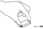
图1A是用户手持的医疗器械的第一实施例的相应于一第一使用状态的透视图,FIG. 1A is a perspective view corresponding to a first use state of a first embodiment of a medical device held by a user,
图1B展示了外壳部分被切开的图1A的器械,Figure 1B shows the instrument of Figure 1A with the housing partially cut away,
图1C展示了外壳部分被去除的图1A的器械,Figure 1C shows the device of Figure 1A with the housing partially removed,
图1D展示了从一个不同角度观察的外壳部分被切开的图1A的器械,Figure 1D shows the device of Figure 1A with the housing partially cut away, viewed from a different angle,
图1E展示了外壳部分被去除的图1D的器械,Figure 1E shows the device of Figure 1D with the housing partially removed,
图2A-2E展示了相应于图1A-1E的一中间使用状态,Figures 2A-2E illustrate an intermediate state of use corresponding to Figures 1A-1E,
图3A-3E展示了相应于图1A-1E的一第二使用状态,Figures 3A-3E show a second state of use corresponding to Figures 1A-1E,
图4A是用户手持的医疗器械的第二实施例的相应于一第一使用状态的透视图,4A is a perspective view corresponding to a first use state of a second embodiment of a medical device held by a user,
图4B展示了外壳部分被切开的图4A的器械,Figure 4B shows the instrument of Figure 4A with the housing partially cut away,
图4C展示了外壳部分被去除的图4A的器械,Figure 4C shows the instrument of Figure 4A with the housing partially removed,
图4D展示了从一个不同角度观察的外壳部分被切开的图4A的器械,Figure 4D shows the device of Figure 4A with the housing partially cut away, viewed from a different angle,
图4E展示了外壳部分被去除的图4D的器械,Figure 4E shows the device of Figure 4D with the housing partially removed,
图5A-5E展示了相应于图4A-4E的一中间使用状态,Figures 5A-5E show an intermediate state of use corresponding to Figures 4A-4E,
图6A-6E展示了相应于图4A-4E的一第二使用状态,Figures 6A-6E show a second state of use corresponding to Figures 4A-4E,
图7A展示了一个经皮器械单元,Figure 7A shows a percutaneous device unit,
图7B展示了另一个经皮器械单元,Figure 7B shows another percutaneous device unit,
图8A-8D展示了适用于本发明的不同的排出装置,Figures 8A-8D illustrate different ejection devices suitable for use in the present invention,
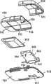
图9A展示了从上方观察的一个药剂注射器械的分解图,Figure 9A shows an exploded view of a medicament injection device viewed from above,
图9B展示了从下方观察的图9A的药剂注射器械的分解图,Figure 9B shows an exploded view of the medicament injection device of Figure 9A viewed from below,
图9C和9D展示了包括两个子配件的注射器械,Figures 9C and 9D show an injection device comprising two subassemblies,
图9E展示了装配的初始状态下的注射器械,Figure 9E shows the injection device in its initial state of assembly,
图9F展示了装配的操纵状态下的注射器械,以及Figure 9F shows the injection device in the assembled manipulation state, and
图10A-10C展示了一个套管和一个插入针头组合实施为一个器械的示意图。Figures 10A-10C illustrate a combination of a cannula and an insertion needle implemented as a device.
图中,用相同的附图标记指示相同的结构。In the drawings, the same structures are denoted by the same reference numerals.
具体实施方式Detailed ways
当在下文中使用诸如“上”、“下”、“左”、“右”、“水平”和“垂直”之类的措辞或类似的相对关系时,仅仅指的是附图,而不是实际的应用情况。When terms such as "upper", "lower", "left", "right", "horizontal" and "vertical" or similar relative relationships are used hereinafter, they are referring to the drawings only and not to the actual Application situation.
附图1-3以示意图的形式给出了按照本发明的医疗器械的不同应用状态的立体图。相应地,不同结构的构造以及这里的相对尺寸关系仅仅用来满足图解说明的目的。Figures 1-3 show perspective views of different application states of the medical device according to the present invention in the form of schematic diagrams. Accordingly, the configuration of the different structures and the relative dimensional relationships herein are for illustration purposes only.
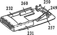
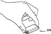
更加具体地讲,附图1A表示由用户拿着的医疗器械100的第一实施方式。该医疗器械包括具有上部外壳110和下部底板部分120的外壳,该外壳提供一个空腔,其中通过一个开口滑动地收纳着致动构件130,该致动构件可沿着该器械的纵向移动。底板部分包括粘合安装面,适于贴敷在患者的皮肤上,该安装面总体上是平的,并且定义了一个总平面。致动构件包括有棱纹的区域,棱纹区域使得用户易于抓握,例如,易于如图所示用第一和第二指抓握。More specifically, FIG. 1A shows a first embodiment of a
按照所示的实施方式,将致动构件形成为具有相对侧边部分131、132的框架,这两个侧边部分131、132适于与上部外壳部分的内表面部分滑动接合,该内表面部分包括纵向凸脊,这些凸脊容纳在形成于侧边部分的外表面上的相应凹槽中。这两个侧边部分由与其外端相对应的按键部分135和与其内端相对应的横梁部分134连接起来,横梁部分包括具有片簧137形式的弹性装置,该片簧137具有取向相对于底板部分倾斜的自由端部分,该片簧用作插入弹簧。该片簧可以是附着在横梁部分上的(例如,当由金属合金制成的时),或者也可以与致动构件整体形成(例如,由聚合物制成)。底板部分包括上表面,在该上表面上,形成有凹形活节构件138和斜坡构件139,这两个构件最好是与底板部分整体形成的。斜坡构件包括上斜坡面147,适于接合片簧137的下表面(用作驱动部分,适于接合针头单元上的相应接合部分),该斜坡面终止于上自由边缘148。According to the illustrated embodiment, the actuating member is formed as a frame having opposing
该器械此外还包括针头单元150,该针头单元150通过活节与底板部分相连,该活节使得针头单元能够关于由该活节定义的枢转轴进行枢转,该枢转轴是基本上与安装面相平行地设置的。针头单元包括中空的注射针头(见附图7A),具有远端尖锐出口部分151,适用于刺入患者的皮肤,该出口部分总体上垂直于安装面延伸,并且针头单元还包括尖锐近端入口部分152,该近端入口部分152是基本上沿着枢转轴设置的。远端可以是沿着枢转轴成直线形或弯曲形的,例如,可以是弓形的。针头由针头承载架承载,该承载架包括臂部分153和圆柱形凸活节部分,针头承载架与凹活节构件相连接,从而形成活节。所述臂包括偏压构件,该偏压构件具有从所述臂突出的片簧155的形式,该弹簧与底板构件的上表面相接合,从而提供向上指向的偏压力,迫使针头进入其初始位置。The instrument furthermore comprises a
通过这种结构,针头单元能够在初始位置和第二位置之间枢转,在初始位置上,针头的入口部分缩回在外壳中,在第二位置上,入口部分通过形成在底板部分上的开口(附图中未示出)相对于安装面而突出。按照所公开的实施方式,活节是由分属于针头承载架和外壳的共同操作的构件来实现的,不过,也可以在外壳上连接“裸”针头,或者将针头承载架和外壳通过薄膜活节彼此连接地形成为一体。With this configuration, the needle unit can pivot between an initial position in which the inlet portion of the needle is retracted in the housing and a second position in which the inlet portion passes through the opening formed on the bottom plate portion. An opening (not shown in the drawings) protrudes relative to the mounting surface. According to the disclosed embodiment, the articulation is achieved by cooperating members belonging to the needle carrier and the housing respectively, however, it is also possible to attach "bare" needles to the housing, or to connect the needle carrier and housing through a membrane. The nodes are connected to each other to form an integral body.
该器械此外还包括储液罐160,适于装容液体药剂,并且在使用状态下,包括与注射针头进行液体流通地出口,并且该器械还包括排出装置(为了更好地图解说明本发明地原理,没有示出),用来将药剂排除储液罐并且借助中空的针头使其穿过患者的皮肤。储液罐和排出装置安装在致动构件上,因此可相对于外壳运动。储液罐包括针头可刺穿的隔膜161,适于与注射针头的入口部分共同作用,该隔膜是基本上对应于枢转轴设置的,从而使得针头单元能够在基本上没有注射针头的入口部分相对于隔膜的非旋转位移的情况下进行枢转。The device further comprises a
下面将参照附图2和3介绍器械100的使用和动作。The use and operation of the
在将该医疗器械放在皮肤部分上之后,用户将致动构件130按压到外壳当中,从而将针头插入并且启动输液装置。在这个动作期间,使致动构件从第一(初始)位置通过中间位置移动到第二位置。在致动构件从第一位置移动到中间位置期间,插入弹簧137相对于斜坡构件移动,这造成驱动部分发生向上赋能运动,从而使得能量可释放地储存在弹簧中,并且还会造成驱动部分移动到处于针头单元的接合部分上方的位置上的位移运动。同时,移动储液罐进入与注射针头的流通状态。此后,致动构件从中间位置到第二位置的催动造成经过赋能的弹簧放松(此时插入弹簧的远端自由边缘滑过斜坡的上自由边缘),借此,插入弹簧快速接合针头单元,从而抵抗着偏压弹簧155的力将其向下偏压到其第二位置。同时,通过插入弹簧锁定在斜坡构件后面,将致动构件锁定到位。After placing the medical device on the skin part, the user presses the
输液装置或传感器电子装置将会与针头的插入相协同地开动,或者是与上面介绍的针头的动作相协同(例如,通过闭合电子触点或通过提供液体连通),或者通过使用额外的启动装置,这种额外的启动装置可以在将该器械安装在皮肤上并且将针头插入之后独立地进行操作。The infusion set or sensor electronics will be actuated in conjunction with the insertion of the needle, either with the action of the needle described above (for example, by closing an electrical contact or by providing fluid communication), or by using an additional activation device , this additional activation device can be operated independently after the device has been mounted on the skin and the needle inserted.
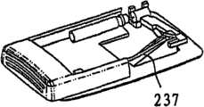
在附图4-6中,给出了与第一实施方式相类似的第二实施方式,该器械包括上部外壳部分210和下部底板部分220,该外壳提供一个空腔,其中通过一个开口滑动地收纳着致动构件230,该致动构件可沿着该器械的纵向移动。该器械此外还包括储液罐260和针头单元250。该器械还包括插入弹簧237和斜坡构件247,不过,与第一实施方式不同,该插入弹簧具有细杆的形式,按照这种样子,将斜坡构件设置成使插入弹簧向上和向侧面偏转。In Figures 4-6, a second embodiment similar to the first is shown, the instrument comprising an
更加具体地讲,斜坡表面稍微有些长,并且具有凹形的横截面构造,这使得杆状弹簧能够在它上面滑动,而不会发生意外的脱落。斜坡终止于斜向的偏转壁249,当弹簧杆抵靠在该偏转壁上而受力时,这个偏转壁将迫使弹簧杆向外运动。该杆可以与致动构件整体形成,或者可以作为独立的构件安装在致动构件上,例如,作为金属弹簧。针头单元类似于第一实施方式,只是该针头单元包括独立形成的接合部分257,该接合部分从承载臂的顶端突出,并且设置在斜坡构件的侧面,刚好在偏转壁的下方。此外,与第一实施方式不同,致动构件并不包括连接侧边部分的内端的横梁部分。More specifically, the ramp surface is somewhat elongated and has a concave cross-sectional configuration, which allows the rod spring to slide over it without accidental dislodgement. The ramp terminates in an
在使用中,第二实施方式是以与第一实施方式相同的方法驱动的,主要的不同之处在于,插入弹簧通过由偏转壁造成的侧向运动从上斜坡面脱离。In use, the second embodiment is actuated in the same way as the first embodiment, the main difference being that the insert spring is disengaged from the upper ramp surface by lateral movement caused by the deflecting wall.
按照上面介绍的实施方式,致动构件进行的是直线运动,不过,按照本发明也可以利用其它的运动。例如,医疗器械可以具有圆形的构造,驱动可以是由用户旋转外壳上部而实现的。在这样的结构中,插入弹簧可以沿径向延伸,同时自由外周端在弯曲的斜坡上滑动。According to the embodiment described above, the actuating member performs a linear movement, however, other movements can also be utilized according to the invention. For example, the medical instrument may have a circular configuration and actuation may be achieved by the user rotating the upper part of the housing. In such a configuration, the insert spring can extend radially while the free peripheral end slides on the curved ramp.
附图7A表示一个针头单元150,该针头单元适于通过活节与外壳构件相连接,使得针头单元能够关于由活节定义的枢转轴枢转。更加具体地讲,针头单元包括具有定义了枢转轴的圆柱形活节部分154的针头承载架和从活节部分垂直于枢转轴伸出的臂构件153。在臂构件的下表面上,设置了偏压装置,该偏压装置具有片簧构件155的形式,适于与外壳的一部分接合。针头承载架承载着具有远端尖锐部分151的针头,该远端尖锐部分适于刺入患者的皮肤,该远端部分总体上垂直于安装面延伸,并且该针头还具有基本上对应于枢转轴设置的近端部分152。这样,可以将针头单元设置成在第一位置和第二位置之间枢转,在第一位置上,针头的远端部分缩回在外壳内,在第二位置上,插入部分相对于安装面突出。在远端部分具有插管形式的情况下,臂构件可以配备针头可刺穿隔膜159,使得插入针头能够通过插管插入,如附图9A所示。按照所示的实施方式,承载架可以是围绕着针头注模形成的,不过,该承载架也可以由薄金属板形成,例如通过粘接剂或焊接将针头安装在该薄金属板上。Figure 7A shows a
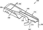
附图7B表示针头单元150的另一种实施方式,适于与外壳构件相连,从而使得针头单元能够关于由活节定义的枢转轴枢转。更加具体地讲,针头单元包括由弯折薄金属板构件形成的针头承载架,该承载架包括上臂560和下臂570,上臂和下臂通过活节部分580彼此连接,使得上下臂能够关于由该活节定义的枢转轴枢转。下臂构成托架571,中空的注射针头590安装在该托架571中(例如通过焊接或粘接),针头具有远端尖锐部分591,适于刺入患者的皮肤,该远端总体上垂直于该器械的安装面延伸,在使用状态下,该器械是通过所述安装面安装的,并且该针头还具有近端部分592,该近端部分是基本上对应于枢转轴设置的。这样,当上臂的一部分,例如,表面561,附着在器械外壳上时,下臂能够在第一位置和第二位置之间枢转,在第一位置上,针头的远端部分缩回在外壳内,在第二位置上,插入部分相对于安装面突出。下臂可以由外部装置移动,不过,最好针头单元提供用来在所述两个位置之间移动下臂的驱动装置。这可以通过薄金属板本身关于活节部分的弹性特性来实现,或者也可以在两个臂之间设置额外的弹簧,从而促使它们分开。为了将下部分锁定在赋能的、可松脱的第一位置上,为上臂配备了弹性的松脱臂562,包括处于其顶端的垫片563,用来将下臂支撑和停止在其第一位置上。当将顶端和垫片移离下臂时,活节和/或弹簧的弹性属性将把下臂偏压到其第二位置上。Figure 7B shows another embodiment of a
按照上面介绍的实施方式,经皮器械是单针头器械的形式(例如,如图所示的注射针头或针头传感器(未示出)),不过,该经皮器械也可以是插管或传感器与插入针头相结合的组合形式,其中插入针头在插入之后取出。According to the embodiments described above, the percutaneous device is in the form of a single needle device (eg, an injection needle as shown or a needle sensor (not shown)), however, the percutaneous device may also be a cannula or sensor with Combination of insertion needles in which the insertion needle is removed after insertion.
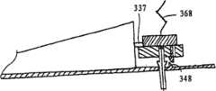
这样,附图10A-10C以示意图形式表示如何在参照附图4-6介绍的那种类型的器械300(局部示出)实现插管和插入针头的组合。更加具体地讲,配备了附图7中所示类型的经皮器械单元350,不过,与针头单元150不同,该经皮器械单元包括由下臂部分353承载的相对较软的插管351(例如可以是软特氟纶
在使用的状态下,通过由用户使插入弹簧沿着斜坡向上移动,对插入弹簧赋能,然后使其脱离斜坡以接合下臂,从而使经皮器械单元朝向如图10B所示的伸出位置枢转。在其完全伸出位置上,插管的锁定装置接合与该器械的外壳(这里是:下表面上的开口)相接合,并且联接脱离构件348与臂联接装置相接合,从而使上臂与下臂脱离,藉此,上臂在弹簧构件368的作用下朝向其初始位置移动,从而从插管中抽出插入针头,见附图10C。按照所示的实施方式,插管是不可缩回地锁定在外壳上的,不过,最好在下臂(或插管)与外壳之间设置可脱离锁定装置,这使得插管能够在将所使用的器械从其附着的皮肤部分上取下之前或之后从该插管的伸出位置上缩回。In the use state, the percutaneous device unit is oriented toward the extended position shown in FIG. pivot. In its fully extended position, the locking device of the cannula engages with the housing (here: the opening on the lower surface) of the instrument, and the
按照上面介绍的实施方式,所介绍的医疗器械包括储液罐,不过,为了更好地图解说明本发明的原理,在附图中省略了用来从储液罐中排出药剂的装置。这样的排除装置(和储液罐一样,并不构成本发明的基本形式的一部分)可以是适于安排在可安装在皮肤上的药剂输送器械内的任何类型。此外,由于本发明的针头也可以具有针头传感器的形式,因此该医疗器械的内部可以包括适于与针头传感器协同工作的传感器装置。According to the above-described embodiments, the described medical device includes a liquid storage tank, however, in order to better illustrate the principle of the present invention, the device for discharging medicine from the liquid storage tank is omitted in the drawings. Such expulsion means (which, like the reservoir, does not form part of the basic form of the invention) may be of any type suitable for arrangement within a skin-mountable drug delivery device. Furthermore, since the needle of the present invention may also have the form of a needle sensor, the interior of the medical device may comprise sensor means adapted to cooperate with the needle sensor.
在附图8A-8D中,示意性地给出了适于由本发明采用的排出装置的例子,不过,这些仅仅是例子。更加具体地讲,附图8A表示一种泵结构,包括:药剂装容筒1010,具有末端封闭构件1011,使得针头能够与之连接,并且该药剂装容筒还具有滑动地安装在其内的活塞1015;弹性有齿活塞杆1020(例如美国专利6302869中公开的);电动机1030,借助蜗杆结构1031驱动活塞杆,以从药筒中排出药剂;该电机由控制装置1040控制,并且控制装置和电机所用的能量是由电池1050提供的。当将针头插入(借助什么没有示出),可以启动该泵,或者可以通过单独的可由用户启动的装置(未示出)在插入器从输液器械中分离出来之后启动该泵。Examples of ejection means suitable for use with the present invention are shown schematically in Figures 8A-8D, however, these are examples only. More specifically, Figure 8A shows a pump structure comprising: a medicament containing cartridge 1010 having an end closure member 1011 so that a needle can be connected thereto, and having a medicament containing cartridge slidably mounted therein. Piston 1015; elastic toothed piston rod 1020 (such as disclosed in US Patent 6302869); electric motor 1030, driving the piston rod by means of worm structure 1031, to expel medicament from the cartridge; this motor is controlled by control device 1040, and the control device and motor The energy used is provided by the battery 1050 . The pump may be activated when the needle is inserted (by means of what is not shown), or may be activated by a separate user-activatable device (not shown) after the inserter has been detached from the infusion set.
附图8B表示一种泵结构,包括:药剂装容筒1110,具有远端和近端封闭构件1111、1112和滑动地安排在其中的活塞1115;气体发生装置1120,通过导管1121与药筒的内部进行流通,用于驱动活塞,以从药筒中排出药剂;该气体发生装置是由控制装置1140控制的,并且控制装置和其它发生所用的能量是由电池1150提供的。该泵可以如上面所述的那样启动。在例如美国专利5858001中可以找到这种用于药剂输送器械的气体发生装置的详细公开内容。Accompanying drawing 8B shows a kind of pump structure, comprises:
附图8C表示一种泵结构,包括:药剂装容筒1210,具有远端和近端封闭构件1211、1212和滑动地安排在其中的活塞1215;渗透引擎1220,通过导管1221与药筒的内部进行流通,用于驱动活塞,以从药筒中排出药剂。渗透引擎包括装容着盐溶液的第一刚性储液罐1225和装容着水的第二可折叠储液罐1226,这两个储液罐由半透膜1227隔开。当供应给用户时,第二储液罐和半透膜之间的流体连接1228是由用户可切断的隔膜(例如,不坚固焊缝)封闭的,在将这个隔膜切断时,使得渗透处理开始,通过半透膜将水从第二储液罐中抽出并且抽入第一储液罐中。该泵可以如上面所述那样启动。在例如美国专利5169390中可以找到渗透驱动原理的详细公开内容。Accompanying drawing 8C shows a kind of pump structure, comprises:
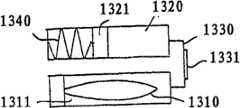
附图8D表示一种泵结构,包括:药剂装容弹性储液罐1310,设置在刚性充液次级储液罐1311中,该次级储液罐与主储液罐1320通过导管1330进行流通,该导管1330包括限流器1331。主储液罐具有带可移动活塞1321的圆筒形式,并且装容着粘性的驱动流体。设置了一个弹簧来作用在活塞上,以从第一储液罐向第二储液罐驱动流体,从而在弹性储液罐与注射针头(未示出)相连时,从该弹性储液罐中排出药剂。流速由弹簧在驱动流体中产生的压力、驱动流体的粘度和限流器中的流阻(排放孔原理)决定。当将针头插入(借助什么没有示出),可以通过拉紧弹簧或通过放松预先加压的弹簧来启动该泵,或者可以通过单独的可由用户启动的装置(未示出)在插入器从输液器械中分离出来之后,通过拉紧弹簧或通过放松预先加压的弹簧来启动该泵。从DE2552446中可以获得这种用于药剂注射的原理的例子。按照另外一种可供选用的结构,可以对药剂储液罐直接加压,以通过限流器排出药剂,例如,美国专利6074369中所公开的结构。Accompanying drawing 8D shows a kind of pump structure, comprises: the medicament containing elastic
按照上面介绍的实施方式,针头单元主要适用于由可致动的驱动装置来致动,不过,参照附图9A-9F,给出了这样一种药剂注射器械:它适于通过移动与安装面平行的致动构件来进行手动致动。According to the embodiment described above, the needle unit is mainly adapted to be actuated by the actuatable drive means, however, with reference to the accompanying drawings 9A-9F, a medicament injection device is shown: it is adapted to pass through the moving and mounting surface parallel actuation members for manual actuation.
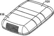
更加具体地讲,药剂注射器械901包括底板910、第一盖构件920和第二盖构件930,这三个单元组合在一起形成外壳,在该外壳内设置有泵组件940和弹性药剂储液罐950。More specifically, the
底板包括:下部总体为平面的表面918,适于与用户的皮肤表面相接合地安装;和上表面919,配备有连接装置,使得第一和第二盖构件以及泵组件940能够安装在底板上。更加具体地讲,底板包括:三个直立的挂钩构件911,适于啮合第一盖构件上的相应挂钩结构921,从而将这两个构件以速动方式彼此锁定在一起;以及一对平行设置的反向构件912,具有向外开口的槽,适于啮合第二盖构件上的相应凸缘结构931,使得这两个构件能够以彼此滑动啮合的形式安装。为了控制这两个构件之间的运动,槽和凸缘可以配备相应的棘齿或锁定装置916、932。为了帮助第二盖构件在将其朝向第一盖构件移动时对准,底板包括凸脊构件913,适于啮合第二盖构件上的相应槽结构933。底板构件此外还包括小孔914、适于啮合泵组件的部分圆柱形“凹”活节构件915以及与活节构件相关的开口917。The base plate comprises: a lower generally
泵组件940包括隔膜泵以及控制装置、致动装置(例如,加热装置)、接触装置和驱动泵的能量源。该泵组件由(部分)圆柱形活节体941构成,从该活节体941伸出泵体942,在该泵体中设置有泵和驱动装置。在活节体的下表面上,设置有啮合构件947。该泵的入口与沿轴向从活节体的端部伸出的入口针头943进行流通,泵的出口与从泵体的下表面948伸出的注射针头944进行流通,两个针头都具有尖锐自由端。活节体适于通过将啮合构件947设置在开口917中而枢转地容纳在活节构件915中,以防止泵组件的轴向位移,同时使注射针头与小孔914对齐。The
弹性储液罐950具有由柔性材料形成的囊状或袋状形式,并且配备有针头可刺穿连接装置,例如,自动封闭隔膜(未示出)。该储液罐很容易折叠收缩,使得装容在其中的药剂能够由泵吸出,而不需要额外的排出装置。储液罐由适当的装置安装并保持在第二盖构件下面的位置上。按照所示的实施方式,储液罐预先充满了药剂,比如胰岛素,不过,该储液罐也适于由用户在使用之前填充。The
上面介绍的组成部分组装在两个子组件(见附图9C和9D),主组件960和储液罐970之内,这使得(如果需要的话)这些组件能够得到独立消毒。更加具体地讲,主组件包括:底板构件,具有安装在其顶部上的第一外壳构件,提供一个空腔,在该空腔中,泵组件940枢转地设置在活节构件915中;而储液罐组件包括:第二外壳构件,具有对应其下表面安装的储液罐。可以将活节构成为提供向上的偏压力,防止泵组件向下枢转。第二外壳构件配备有具有有槽区域934的端部和相对设置的套筒部分935,该套筒部分935适于在在第一盖构件下滑动,以及与第二外壳构件的下表面相关的下斜坡构件936,下面将更加详细地解释说明其功能。The components described above are assembled within two subassemblies (see Figures 9C and 9D), the main assembly 960 and the reservoir 970, which allow (if desired) these assemblies to be sterilized independently. More specifically, the main assembly includes: a base member having a first housing member mounted on top thereof providing a cavity in which the
药剂注射器械901以对应于附图9E所示的初始状态那样组装起来的两个子组件的形式提供给用户。更加具体地讲,储液罐组件借助连接构件912、931与底板构件滑动啮合地安装,从而在第二盖构件和底板构件之间形成包围着储液罐的空腔,储液罐连接装置设置成沿轴向与入口针头对齐。在初始状态下,储液罐组件并没有充分朝向第一盖构件移动,不过,套筒部分地插入在第一盖构件下面,这提供了封闭的空腔。可以构成设置在第二盖构件和底板构件之间的锁定或棘齿装置916、932,来防止储液罐组件由用户拆除下来。The
为了启用注射器械,将储液罐组件朝向泵组件移动(见附图9F),藉此,发生了多个动作。更加具体地讲,入口针头943将会刺入储液罐连接装置,提供储液罐和泵之间的流通,并且第二盖构件上的斜坡936将会与泵组件接合,从而使其向下枢转,藉此,使注射针头944穿过小孔914移动。同时,使设置在泵组件上(例如,在泵体的下表面上)的触点装置启动,从而启动泵控制装置并且最终启动泵,不过,得到启动的控制装置可以适于在使泵发生动作之前“等待”来自外部信号的命令信号(例如由遥控装置提供的命令信号)。按照另一种可选的实施方式(未示出),储液罐组件和泵组件可以适于作直线运动,例如,以共线方式移动,此时它们是以“叠置”方式排列的。按照再另一种可供选择的实施方式(未示出),储液罐可以与泵连接,泵的启动和针头的插入是例如通过两个或三个用户致动动作彼此部分或完全独立地完成的。To activate the injection device, the reservoir assembly is moved towards the pump assembly (see Figure 9F), whereby a number of actions occur. More specifically, the
药剂注射器械901可以按照下述方式使用。在将衬套除掉之后,将该器械放在用户的适当皮肤部位上,例如,放在腹部区域上,此后,将用作按钮的储液罐组件(由有槽区域931表示)朝向主部分推动,直到它锁定在正确的位置上,如上所述,这造成泵的启动和针头穿过用户的皮肤的经皮插入。取决于控制装置的程序,泵可以开始立即工作,或者可以在泵的动作启动之前等待用户的启动命令,例如,从远程控制者接收到的命令或从设置在该器械上的装置接收到的命令。在按照给定的(基本的)注射速度进行的注射开始之前,该泵最好进行如上面所述的灌注动作。由于最初在注射泵和相关的导管(包括两个针头)中存的空气的容积非常小,在大多数情况下将这种量的空气排入用户体内是可以接受的,不过,如果不希望这样,必须要在将该器械安装在皮肤上之前进行注射器械的致动(即,将这两个组件推到一起)。The
当取下该器械时,可以在针头从下表面突出的情况下,将其在工作状态下从皮肤上拽下来,或者可以在将该器械取下之前,将该器械退回到其初始状态。例如,如果锁定装置设置在套筒和第一盖构件之间,可以通过下推第一盖构件的下表面使该锁定装置松脱。When removing the device, it may be pulled from the skin in the working condition with the needle protruding from the lower surface, or the device may be returned to its original state before the device is removed. For example, if the locking means is provided between the sleeve and the first cover member, the locking means can be released by pushing down on the lower surface of the first cover member.
按照上面介绍的实施方式,针头具有单一针头器械的形式(例如,如图所示的注射针头或针头传感器(未示出)),不过,针头器械(例如,软插管或软针头传感器)也可以与插入针头相组合地经皮插入。According to the embodiments described above, the needle is in the form of a single needle instrument (eg, an injection needle as shown or a needle sensor (not shown)), however, a needle instrument (eg, a soft cannula or a soft needle sensor) also Can be inserted percutaneously in combination with an insertion needle.
这样,按照另一种实施方式,针头单元包括具有远端尖锐终端的插入针头,该插入针头与远端针头部分(例如,针头传感器的远端针头部分)同轴地可拆除地设置并且支撑着该远端针头部分,该插入针头和针头设置成,当致动针头单元时,同时从它们各自的第一位置枢转到它们各自的第二位置。插入针头可以具有任何期望的结构,比如实心的或有槽的。Thus, according to another embodiment, the needle unit comprises an insertion needle with a distal sharp terminal, removably arranged coaxially with a distal needle portion (for example, a distal needle portion of a needle sensor) and supporting The distal needle part, the insertion needle and the needle are arranged to simultaneously pivot from their respective first position to their respective second position when the needle unit is actuated. The insertion needle can have any desired configuration, such as solid or slotted.
在上面优选实施方式的介绍中,为不同的组成部分提供所介绍的功能的不同的结构和装置的介绍过程达到了使本发明的概念对本领域的技术人员显而易见的程度。针对不同组成部分的详细结构和介绍都看作是本领域技术人员沿着本说明书提出的线索进行的正常设计过程的目标。In the above description of the preferred embodiments, the various structures and means for the various components to provide the described functions have been described so far as to make the concept of the present invention apparent to those skilled in the art. The detailed structure and introduction of the different components are regarded as the goal of a normal design process carried out by those skilled in the art along the lines proposed in this specification.
Claims (16)
Translated fromChineseApplications Claiming Priority (2)
| Application Number | Priority Date | Filing Date | Title |
|---|---|---|---|
| DKPA200300696 | 2003-05-08 | ||
| DKPA200300696 | 2003-05-08 |
Publications (2)
| Publication Number | Publication Date |
|---|---|
| CN101128228A CN101128228A (en) | 2008-02-20 |
| CN100574819Ctrue CN100574819C (en) | 2009-12-30 |
Family
ID=36597060
Family Applications (1)
| Application Number | Title | Priority Date | Filing Date |
|---|---|---|---|
| CN200480012437AExpired - Fee RelatedCN100574819C (en) | 2003-05-08 | 2004-05-10 | Pivotable injection needle unit |
Country Status (6)
| Country | Link |
|---|---|
| US (1) | US7628770B2 (en) |
| EP (1) | EP1631336B1 (en) |
| CN (1) | CN100574819C (en) |
| AT (1) | ATE457761T1 (en) |
| DE (1) | DE602004025568D1 (en) |
| WO (1) | WO2004098682A2 (en) |
Families Citing this family (183)
| Publication number | Priority date | Publication date | Assignee | Title |
|---|---|---|---|---|
| AU2003245872A1 (en) | 2002-07-24 | 2004-02-09 | M 2 Medical A/S | An infusion pump system, an infusion pump unit and an infusion pump |
| WO2004056412A2 (en) | 2002-12-23 | 2004-07-08 | M2 Medical A/S | A disposable, wearable insulin dispensing device, a combination of such a device and a programming controller and a method of controlling the operation of such a device |
| CN1726059A (en) | 2002-11-05 | 2006-01-25 | M2医药有限公司 | Disposable wearable insulin dispensing device, combination of the device and a program controller and method for controlling the operation of the device |
| AU2003291963A1 (en) | 2002-12-23 | 2004-07-14 | M 2 Medical A/S | Flexible piston rod |
| US7753879B2 (en)* | 2004-01-29 | 2010-07-13 | M2 Group Holdings, Inc. | Disposable medicine dispensing device |
| MXPA06010784A (en) | 2004-03-26 | 2006-12-15 | Unomedical As | Injector device for infusion set. |
| US8057434B2 (en) | 2004-03-31 | 2011-11-15 | Eli Lilly And Company | Injection apparatus having a needle cassette for delivering a pharmaceutical liquid |
| US8062250B2 (en) | 2004-08-10 | 2011-11-22 | Unomedical A/S | Cannula device |
| US20060100581A1 (en)* | 2004-08-13 | 2006-05-11 | Mogensen Lasse W | Reservoir for front end loaded infusion device |
| DE102004039408A1 (en) | 2004-08-13 | 2006-03-02 | Disetronic Licensing Ag | Insertion head for medical or pharmaceutical applications |
| US9788771B2 (en) | 2006-10-23 | 2017-10-17 | Abbott Diabetes Care Inc. | Variable speed sensor insertion devices and methods of use |
| US9398882B2 (en)* | 2005-09-30 | 2016-07-26 | Abbott Diabetes Care Inc. | Method and apparatus for providing analyte sensor and data processing device |
| US8167841B2 (en)* | 2005-01-24 | 2012-05-01 | Novo Nordisk A/S | Transcutaneous device assembly |
| US7985199B2 (en)* | 2005-03-17 | 2011-07-26 | Unomedical A/S | Gateway system |
| EP1877115A1 (en) | 2005-04-06 | 2008-01-16 | M 2 Medical A/S | An actuator |
| EP1762259B2 (en) | 2005-09-12 | 2025-01-01 | Unomedical A/S | Inserter for an infusion set with a first and second spring units |
| US8409142B2 (en) | 2005-09-26 | 2013-04-02 | Asante Solutions, Inc. | Operating an infusion pump system |
| US8057436B2 (en) | 2005-09-26 | 2011-11-15 | Asante Solutions, Inc. | Dispensing fluid from an infusion pump system |
| US7534226B2 (en) | 2005-09-26 | 2009-05-19 | M2 Group Holdings, Inc. | Dispensing fluid from an infusion pump system |
| US8105279B2 (en) | 2005-09-26 | 2012-01-31 | M2 Group Holdings, Inc. | Dispensing fluid from an infusion pump system |
| DK1933902T3 (en) | 2005-09-26 | 2015-03-23 | Asante Solutions Inc | Infusion Pump WITH A DRIVE THAT HAVE AN PALLEGEME- AND CONGEST HAGE-COMBINATION |
| US8551046B2 (en) | 2006-09-18 | 2013-10-08 | Asante Solutions, Inc. | Dispensing fluid from an infusion pump system |
| WO2007056592A2 (en) | 2005-11-08 | 2007-05-18 | M2 Medical A/S | Method and system for manual and autonomous control of an infusion pump |
| US8475408B2 (en) | 2005-11-08 | 2013-07-02 | Asante Solutions, Inc. | Infusion pump system |
| US9615851B2 (en) | 2005-11-11 | 2017-04-11 | Waveform Technologies, Inc. | Method and apparatus for insertion of a sensor |
| DK1962926T3 (en) | 2005-12-23 | 2009-09-28 | Unomedical As | injection device |
| WO2007098771A2 (en) | 2006-02-28 | 2007-09-07 | Unomedical A/S | Inserter for infusion part and infusion part provided with needle protector |
| EP1997233B1 (en) | 2006-03-13 | 2014-03-05 | Novo Nordisk A/S | Secure pairing of electronic devices using dual means of communication |
| US8118509B2 (en) | 2006-05-08 | 2012-02-21 | Dianna Marcellus | Automatic substance applicator system |
| EP2032188A1 (en) | 2006-06-06 | 2009-03-11 | Novo Nordisk A/S | Assembly comprising skin-mountable device and packaging therefore |
| CA2653631A1 (en) | 2006-06-07 | 2007-12-13 | Unomedical A/S | Inserter |
| CA2653764A1 (en) | 2006-06-09 | 2007-12-13 | Unomedical A/S | Mounting pad |
| US9119582B2 (en) | 2006-06-30 | 2015-09-01 | Abbott Diabetes Care, Inc. | Integrated analyte sensor and infusion device and methods therefor |
| JP2009545341A (en) | 2006-08-02 | 2009-12-24 | ウノメディカル アクティーゼルスカブ | Cannula and delivery device |
| EP1917990A1 (en) | 2006-10-31 | 2008-05-07 | Unomedical A/S | Infusion set |
| ATE485858T1 (en) | 2007-03-14 | 2010-11-15 | Hoffmann La Roche | INSERTION HEAD FOR MEDICAL OR PHARMACEUTICAL APPLICATIONS |
| ATE477011T1 (en) | 2007-03-14 | 2010-08-15 | Hoffmann La Roche | INSERTION DEVICE FOR AN INSERTION HEAD, IN PARTICULAR FOR AN INFUSION SET |
| US7794426B2 (en) | 2007-05-21 | 2010-09-14 | Asante Solutions, Inc. | Infusion pump system with contamination-resistant features |
| US7833196B2 (en) | 2007-05-21 | 2010-11-16 | Asante Solutions, Inc. | Illumination instrument for an infusion pump |
| US7892199B2 (en) | 2007-05-21 | 2011-02-22 | Asante Solutions, Inc. | Occlusion sensing for an infusion pump |
| US7981102B2 (en) | 2007-05-21 | 2011-07-19 | Asante Solutions, Inc. | Removable controller for an infusion pump |
| EP2155311B1 (en) | 2007-06-20 | 2013-01-02 | Unomedical A/S | A method and an apparatus for making a catheter |
| AU2008270327A1 (en) | 2007-07-03 | 2009-01-08 | Unomedical A/S | Inserter having bistable equilibrium states |
| DE602008005153D1 (en) | 2007-07-10 | 2011-04-07 | Unomedical As | INSERT WITH TWO SPRINGS |
| AU2008277763B2 (en) | 2007-07-18 | 2011-11-10 | Unomedical A/S | Insertion device with pivoting action |
| US7717903B2 (en) | 2007-09-06 | 2010-05-18 | M2 Group Holdings, Inc. | Operating an infusion pump system |
| US7828528B2 (en)* | 2007-09-06 | 2010-11-09 | Asante Solutions, Inc. | Occlusion sensing system for infusion pumps |
| US8287514B2 (en) | 2007-09-07 | 2012-10-16 | Asante Solutions, Inc. | Power management techniques for an infusion pump system |
| US7879026B2 (en) | 2007-09-07 | 2011-02-01 | Asante Solutions, Inc. | Controlled adjustment of medicine dispensation from an infusion pump device |
| US7935076B2 (en) | 2007-09-07 | 2011-05-03 | Asante Solutions, Inc. | Activity sensing techniques for an infusion pump system |
| US8032226B2 (en) | 2007-09-07 | 2011-10-04 | Asante Solutions, Inc. | User profile backup system for an infusion pump device |
| US9656019B2 (en) | 2007-10-02 | 2017-05-23 | Medimop Medical Projects Ltd. | Apparatuses for securing components of a drug delivery system during transport and methods of using same |
| US7967795B1 (en) | 2010-01-19 | 2011-06-28 | Lamodel Ltd. | Cartridge interface assembly with driving plunger |
| US9345836B2 (en) | 2007-10-02 | 2016-05-24 | Medimop Medical Projects Ltd. | Disengagement resistant telescoping assembly and unidirectional method of assembly for such |
| BRPI0817907B8 (en) | 2007-10-02 | 2021-06-22 | Lamodel Ltd | apparatus for administering a substance to an individual |
| US10420880B2 (en) | 2007-10-02 | 2019-09-24 | West Pharma. Services IL, Ltd. | Key for securing components of a drug delivery system during assembly and/or transport and methods of using same |
| ATE522240T1 (en) | 2008-02-13 | 2011-09-15 | Unomedical As | SEAL BETWEEN A CANNULAR PART AND A FLUID PATH |
| US9566384B2 (en) | 2008-02-20 | 2017-02-14 | Unomedical A/S | Insertion device with horizontally moving part |
| CA2930329A1 (en)* | 2008-08-18 | 2010-02-25 | Calibra Medical, Inc. | Drug infusion system with reusable and disposable components |
| US7959598B2 (en) | 2008-08-20 | 2011-06-14 | Asante Solutions, Inc. | Infusion pump systems and methods |
| US12097357B2 (en) | 2008-09-15 | 2024-09-24 | West Pharma. Services IL, Ltd. | Stabilized pen injector |
| US9393369B2 (en) | 2008-09-15 | 2016-07-19 | Medimop Medical Projects Ltd. | Stabilized pen injector |
| AU2009331635A1 (en) | 2008-12-22 | 2011-06-23 | Unomedical A/S | Medical device comprising adhesive pad |
| US8152779B2 (en) | 2008-12-30 | 2012-04-10 | Medimop Medical Projects Ltd. | Needle assembly for drug pump |
| US9375529B2 (en) | 2009-09-02 | 2016-06-28 | Becton, Dickinson And Company | Extended use medical device |
| EP3384942B1 (en) | 2009-01-12 | 2025-09-17 | Becton, Dickinson and Company | Infusion set and/or patch pump having at least one of an in-dwelling rigid catheter with flexible features and/or a flexible catheter attachment |
| US8939928B2 (en) | 2009-07-23 | 2015-01-27 | Becton, Dickinson And Company | Medical device having capacitive coupling communication and energy harvesting |
| AU2010277755A1 (en) | 2009-07-30 | 2012-02-02 | Unomedical A/S | Inserter device with horizontal moving part |
| KR20120047896A (en) | 2009-08-07 | 2012-05-14 | 우노메디컬 에이/에스 | Delivery device with sensor and one or more cannulas |
| EP3001194B1 (en) | 2009-08-31 | 2019-04-17 | Abbott Diabetes Care, Inc. | Medical devices and methods |
| US10092691B2 (en) | 2009-09-02 | 2018-10-09 | Becton, Dickinson And Company | Flexible and conformal patch pump |
| US10071196B2 (en) | 2012-05-15 | 2018-09-11 | West Pharma. Services IL, Ltd. | Method for selectively powering a battery-operated drug-delivery device and device therefor |
| US8157769B2 (en) | 2009-09-15 | 2012-04-17 | Medimop Medical Projects Ltd. | Cartridge insertion assembly for drug delivery system |
| US10071198B2 (en) | 2012-11-02 | 2018-09-11 | West Pharma. Servicees IL, Ltd. | Adhesive structure for medical device |
| JP5650241B2 (en) | 2009-12-16 | 2015-01-07 | ベクトン・ディキンソン・アンド・カンパニーBecton, Dickinson And Company | Self injection device |
| JP5650755B2 (en) | 2009-12-16 | 2015-01-07 | ベクトン・ディキンソン・アンド・カンパニーBecton, Dickinson And Company | Self injection device |
| WO2011075103A1 (en) | 2009-12-16 | 2011-06-23 | Becton, Dickinson And Company | Self-injection device |
| DK2781228T3 (en) | 2009-12-16 | 2016-03-21 | Becton Dickinson Co | A device for self-injection |
| DK2512560T3 (en) | 2009-12-16 | 2018-07-16 | Becton Dickinson Co | Even injector device |
| CN102753221B (en) | 2009-12-16 | 2017-04-26 | 贝克顿·迪金森公司 | self-injection device |
| CN102665549B (en)* | 2009-12-24 | 2015-07-01 | 爱科来株式会社 | Measurement device and sensor placement method |
| US8348898B2 (en) | 2010-01-19 | 2013-01-08 | Medimop Medical Projects Ltd. | Automatic needle for drug pump |
| KR20130018783A (en) | 2010-03-30 | 2013-02-25 | 우노메디컬 에이/에스 | Medical device |
| EP2569031B1 (en) | 2010-05-10 | 2017-10-11 | Medimop Medical Projects Ltd. | Low volume accurate injector |
| BR112012029642B1 (en)* | 2010-05-20 | 2020-05-26 | Becton, Dickinson And Company | DRUG ADMINISTRATION DEVICE |
| USD669165S1 (en) | 2010-05-27 | 2012-10-16 | Asante Solutions, Inc. | Infusion pump |
| CN103153360B (en) | 2010-09-02 | 2016-04-06 | 贝克顿·迪金森公司 | Have band activate interceptor pin lid from injection device |
| US8585677B2 (en) | 2010-09-21 | 2013-11-19 | Brigham Young University | Laminar injection apparatus and method |
| EP2433663A1 (en) | 2010-09-27 | 2012-03-28 | Unomedical A/S | Insertion system |
| EP2436412A1 (en) | 2010-10-04 | 2012-04-04 | Unomedical A/S | A sprinkler cannula |
| US8814831B2 (en) | 2010-11-30 | 2014-08-26 | Becton, Dickinson And Company | Ballistic microneedle infusion device |
| US9950109B2 (en) | 2010-11-30 | 2018-04-24 | Becton, Dickinson And Company | Slide-activated angled inserter and cantilevered ballistic insertion for intradermal drug infusion |
| US8795230B2 (en) | 2010-11-30 | 2014-08-05 | Becton, Dickinson And Company | Adjustable height needle infusion device |
| US8852152B2 (en) | 2011-02-09 | 2014-10-07 | Asante Solutions, Inc. | Infusion pump systems and methods |
| US8454581B2 (en) | 2011-03-16 | 2013-06-04 | Asante Solutions, Inc. | Infusion pump systems and methods |
| USD702834S1 (en) | 2011-03-22 | 2014-04-15 | Medimop Medical Projects Ltd. | Cartridge for use in injection device |
| US8585657B2 (en) | 2011-06-21 | 2013-11-19 | Asante Solutions, Inc. | Dispensing fluid from an infusion pump system |
| US8808230B2 (en) | 2011-09-07 | 2014-08-19 | Asante Solutions, Inc. | Occlusion detection for an infusion pump system |
| WO2013050277A1 (en) | 2011-10-05 | 2013-04-11 | Unomedical A/S | Inserter for simultaneous insertion of multiple transcutaneous parts |
| EP2583715A1 (en) | 2011-10-19 | 2013-04-24 | Unomedical A/S | Infusion tube system and method for manufacture |
| US9440051B2 (en) | 2011-10-27 | 2016-09-13 | Unomedical A/S | Inserter for a multiplicity of subcutaneous parts |
| USD692997S1 (en)* | 2011-11-08 | 2013-11-05 | Becton Dickinson France, S.A.S. | Microinfuser |
| USD693455S1 (en)* | 2011-11-08 | 2013-11-12 | Becton, Dickinson And Company | Microinfuser |
| USD692552S1 (en)* | 2011-11-08 | 2013-10-29 | Becton Dickinson France, S.A.S. | Microinfuser |
| EP2809375B1 (en) | 2012-01-31 | 2021-08-11 | Medimop Medical Projects Ltd. | Time dependent drug delivery apparatus |
| CN204910157U (en) | 2012-03-05 | 2015-12-30 | 贝克顿·迪金森公司 | System for be used for at body liquid conveying |
| US9072827B2 (en) | 2012-03-26 | 2015-07-07 | Medimop Medical Projects Ltd. | Fail safe point protector for needle safety flap |
| US9463280B2 (en) | 2012-03-26 | 2016-10-11 | Medimop Medical Projects Ltd. | Motion activated septum puncturing drug delivery device |
| US10668213B2 (en) | 2012-03-26 | 2020-06-02 | West Pharma. Services IL, Ltd. | Motion activated mechanisms for a drug delivery device |
| US8454557B1 (en) | 2012-07-19 | 2013-06-04 | Asante Solutions, Inc. | Infusion pump system and method |
| US8454562B1 (en) | 2012-07-20 | 2013-06-04 | Asante Solutions, Inc. | Infusion pump system and method |
| US9427523B2 (en) | 2012-12-10 | 2016-08-30 | Bigfoot Biomedical, Inc. | Infusion pump system and method |
| US20140276536A1 (en) | 2013-03-14 | 2014-09-18 | Asante Solutions, Inc. | Infusion Pump System and Methods |
| US9421323B2 (en) | 2013-01-03 | 2016-08-23 | Medimop Medical Projects Ltd. | Door and doorstop for portable one use drug delivery apparatus |
| US9446186B2 (en) | 2013-03-01 | 2016-09-20 | Bigfoot Biomedical, Inc. | Operating an infusion pump system |
| US9011164B2 (en) | 2013-04-30 | 2015-04-21 | Medimop Medical Projects Ltd. | Clip contact for easy installation of printed circuit board PCB |
| US9889256B2 (en) | 2013-05-03 | 2018-02-13 | Medimop Medical Projects Ltd. | Sensing a status of an infuser based on sensing motor control and power input |
| US9446187B2 (en) | 2013-06-03 | 2016-09-20 | Bigfoot Biomedical, Inc. | Infusion pump system and method |
| US9457141B2 (en) | 2013-06-03 | 2016-10-04 | Bigfoot Biomedical, Inc. | Infusion pump system and method |
| US9561324B2 (en) | 2013-07-19 | 2017-02-07 | Bigfoot Biomedical, Inc. | Infusion pump system and method |
| AU2014308659B2 (en) | 2013-08-23 | 2018-11-01 | Unl Holdings Llc | Integrated pierceable seal fluid pathway connection and drug containers for drug delivery pumps |
| US9375537B2 (en) | 2013-10-14 | 2016-06-28 | Medtronic Minimed, Inc. | Therapeutic agent injection device |
| US10569015B2 (en) | 2013-12-02 | 2020-02-25 | Bigfoot Biomedical, Inc. | Infusion pump system and method |
| US10130755B2 (en) | 2013-12-31 | 2018-11-20 | Abbvie Inc. | Devices and methods for delivering a beneficial agent to a user |
| US9610402B2 (en)* | 2014-03-24 | 2017-04-04 | Medtronic Minimed, Inc. | Transcutaneous conduit insertion mechanism with a living hinge for use with a fluid infusion patch pump device |
| US10004845B2 (en) | 2014-04-18 | 2018-06-26 | Becton, Dickinson And Company | Split piston metering pump |
| US9629901B2 (en) | 2014-07-01 | 2017-04-25 | Bigfoot Biomedical, Inc. | Glucagon administration system and methods |
| US9416775B2 (en) | 2014-07-02 | 2016-08-16 | Becton, Dickinson And Company | Internal cam metering pump |
| US10137246B2 (en) | 2014-08-06 | 2018-11-27 | Bigfoot Biomedical, Inc. | Infusion pump assembly and method |
| US9919096B2 (en) | 2014-08-26 | 2018-03-20 | Bigfoot Biomedical, Inc. | Infusion pump system and method |
| US11464899B2 (en) | 2014-08-28 | 2022-10-11 | Becton, Dickinson And Company | Wireless communication for on-body medical devices |
| USD744005S1 (en) | 2014-12-30 | 2015-11-24 | Abbvie Inc. | Pump |
| USD777247S1 (en) | 2014-12-30 | 2017-01-24 | Abbvie Inc. | Interface portion of a cassette |
| USD746871S1 (en) | 2014-12-30 | 2016-01-05 | Abbvie Inc. | Interface portion of a pump |
| USD777831S1 (en) | 2014-12-30 | 2017-01-31 | Abbvie Inc. | Cassette |
| USD766424S1 (en) | 2014-12-30 | 2016-09-13 | Abbvie Inc. | Delivery device including pump and cassette |
| US9795534B2 (en) | 2015-03-04 | 2017-10-24 | Medimop Medical Projects Ltd. | Compliant coupling assembly for cartridge coupling of a drug delivery device |
| US10251813B2 (en) | 2015-03-04 | 2019-04-09 | West Pharma. Services IL, Ltd. | Flexibly mounted cartridge alignment collar for drug delivery device |
| IL295010B1 (en) | 2015-03-10 | 2025-06-01 | Regeneron Pharma | Pollution-free piercing system and method |
| US9744297B2 (en) | 2015-04-10 | 2017-08-29 | Medimop Medical Projects Ltd. | Needle cannula position as an input to operational control of an injection device |
| US10293120B2 (en) | 2015-04-10 | 2019-05-21 | West Pharma. Services IL, Ltd. | Redundant injection device status indication |
| US9878097B2 (en) | 2015-04-29 | 2018-01-30 | Bigfoot Biomedical, Inc. | Operating an infusion pump system |
| US10149943B2 (en) | 2015-05-29 | 2018-12-11 | West Pharma. Services IL, Ltd. | Linear rotation stabilizer for a telescoping syringe stopper driverdriving assembly |
| CN113181477B (en) | 2015-06-04 | 2023-07-14 | 麦迪麦珀医疗工程有限公司 | Cartridge insertion for drug delivery device |
| USD774640S1 (en) | 2015-07-30 | 2016-12-20 | Becton, Dickinson And Company | Medical injector |
| USD776265S1 (en) | 2015-07-30 | 2017-01-10 | Becton, Dickinson And Company | Medical injector |
| USD776263S1 (en) | 2015-07-30 | 2017-01-10 | Becton, Dickinson And Company | Medical injector |
| USD776264S1 (en) | 2015-07-30 | 2017-01-10 | Becton, Dickinson And Company | Medical injector |
| USD776262S1 (en) | 2015-07-30 | 2017-01-10 | Becton, Dickinson And Company | Medical injector |
| USD794776S1 (en) | 2015-07-30 | 2017-08-15 | Becton, Dickinson And Company | Medical injector |
| USD767120S1 (en) | 2015-07-30 | 2016-09-20 | Becton, Dickinson And Company | Medical injector |
| US10576207B2 (en) | 2015-10-09 | 2020-03-03 | West Pharma. Services IL, Ltd. | Angled syringe patch injector |
| US9987432B2 (en) | 2015-09-22 | 2018-06-05 | West Pharma. Services IL, Ltd. | Rotation resistant friction adapter for plunger driver of drug delivery device |
| US11318254B2 (en) | 2015-10-09 | 2022-05-03 | West Pharma. Services IL, Ltd. | Injector needle cap remover |
| US10449294B1 (en) | 2016-01-05 | 2019-10-22 | Bigfoot Biomedical, Inc. | Operating an infusion pump system |
| AU2016385454B2 (en) | 2016-01-05 | 2021-12-16 | Bigfoot Biomedical, Inc. | Operating multi-modal medicine delivery systems |
| HK1256995A1 (en) | 2016-01-14 | 2019-10-11 | Bigfoot Biomedical, Inc. | Occlusion resolution in medication delivery devices, systems, and methods |
| EP3711793B1 (en) | 2016-01-21 | 2021-12-01 | West Pharma Services IL, Ltd. | A method of connecting a cartridge to an automatic injector |
| US10646643B2 (en) | 2016-01-21 | 2020-05-12 | West Pharma. Services IL, Ltd. | Needle insertion and retraction mechanism |
| JP6885960B2 (en) | 2016-01-21 | 2021-06-16 | ウェスト ファーマ サービシーズ イスラエル リミテッド | Drug delivery device with visual indicators |
| USD809134S1 (en) | 2016-03-10 | 2018-01-30 | Bigfoot Biomedical, Inc. | Infusion pump assembly |
| US11389597B2 (en) | 2016-03-16 | 2022-07-19 | West Pharma. Services IL, Ltd. | Staged telescopic screw assembly having different visual indicators |
| CN109310831B (en) | 2016-06-02 | 2021-11-23 | 西医药服务以色列有限公司 | Three position needle retraction |
| CN109561833B (en) | 2016-06-22 | 2022-04-29 | 豪夫迈·罗氏有限公司 | Medical device for percutaneous insertion of an insertable element into body tissue |
| JP7059251B2 (en) | 2016-08-01 | 2022-04-25 | ウェスト ファーマ サービシーズ イスラエル リミテッド | A spring that prevents the door from closing halfway |
| US11338090B2 (en) | 2016-08-01 | 2022-05-24 | West Pharma. Services IL, Ltd. | Anti-rotation cartridge pin |
| JP6970733B2 (en) | 2016-08-02 | 2021-11-24 | サノフィ−アベンティス・ドイチュラント・ゲゼルシャフト・ミット・ベシュレンクテル・ハフツング | Drug delivery device |
| AU2017335762B2 (en) | 2016-09-27 | 2022-03-17 | Bigfoot Biomedical, Inc. | Medicine injection and disease management systems, devices, and methods |
| EP3500161A4 (en) | 2016-12-12 | 2020-01-08 | Bigfoot Biomedical, Inc. | ALARMS AND WARNINGS FOR MEDICINE DELIVERY DEVICES AND RELATED SYSTEMS AND METHODS |
| USD836769S1 (en) | 2016-12-12 | 2018-12-25 | Bigfoot Biomedical, Inc. | Insulin delivery controller |
| US11071478B2 (en) | 2017-01-23 | 2021-07-27 | Abbott Diabetes Care Inc. | Systems, devices and methods for analyte sensor insertion |
| AU2018221351B2 (en) | 2017-02-17 | 2023-02-23 | Amgen Inc. | Insertion mechanism for drug delivery device |
| EP3618712A1 (en) | 2017-05-03 | 2020-03-11 | Abbott Diabetes Care Inc. | Systems, devices, and methods with duration-based adjustment of sensor data |
| CN119950880A (en) | 2017-05-05 | 2025-05-09 | 里珍纳龙药品有限公司 | Auto-injectors and related methods of use |
| EP3630226A1 (en) | 2017-05-30 | 2020-04-08 | West Pharma. Services Il, Ltd. | Modular drive train for wearable injector |
| USD839294S1 (en) | 2017-06-16 | 2019-01-29 | Bigfoot Biomedical, Inc. | Display screen with graphical user interface for closed-loop medication delivery |
| EP3651647A1 (en) | 2017-07-13 | 2020-05-20 | Bigfoot Biomedical, Inc. | Multi-scale display of blood glucose information |
| US11918348B2 (en) | 2017-12-05 | 2024-03-05 | Abbott Diabetes Care Inc. | Medical devices having a dynamic surface profile and methods for production and use thereof |
| JP7402799B2 (en) | 2017-12-22 | 2023-12-21 | ウェスト ファーマ サービシーズ イスラエル リミテッド | Syringes available with different cartridge sizes |
| EP4218567B1 (en) | 2018-06-07 | 2025-03-12 | Abbott Diabetes Care, Inc. | Focused sterilization and sterilized sub-assemblies for analyte monitoring systems |
| CN112423664B (en) | 2018-06-07 | 2025-01-21 | 雅培糖尿病护理公司 | Focused sterilization and sterilized sub-assemblies for analyte monitoring systems |
| CA3188510A1 (en) | 2020-08-31 | 2022-03-03 | Vivek S. RAO | Systems, devices, and methods for analyte sensor insertion |
| USD1007676S1 (en) | 2021-11-16 | 2023-12-12 | Regeneron Pharmaceuticals, Inc. | Wearable autoinjector |
Citations (3)
| Publication number | Priority date | Publication date | Assignee | Title |
|---|---|---|---|---|
| US5858001A (en)* | 1995-12-11 | 1999-01-12 | Elan Medical Technologies Limited | Cartridge-based drug delivery device |
| EP0937475A2 (en)* | 1998-02-20 | 1999-08-25 | Becton, Dickinson and Company | Low-profile automatic injection device with self-emptying reservoir |
| US6500150B1 (en)* | 1997-06-16 | 2002-12-31 | Elan Pharma International Limited | Pre-filled drug-delivery device and method of manufacture and assembly of same |
Family Cites Families (18)
| Publication number | Priority date | Publication date | Assignee | Title |
|---|---|---|---|---|
| US123740A (en)* | 1872-02-13 | Improvement in bracelets | ||
| US55711A (en)* | 1866-06-19 | Improvement in hydrants | ||
| US69546A (en)* | 1867-10-08 | Improvement in teaoe-fastening | ||
| US858001A (en)* | 1905-02-07 | 1907-06-25 | Mortimer A Howe | Separable double letter-sheet. |
| US2605765A (en) | 1947-06-05 | 1952-08-05 | Kollsman Paul | Automatic syringe |
| US4340048A (en) | 1981-03-28 | 1982-07-20 | Alza Corporation | Self-driven hypodermic injector |
| US4552561A (en) | 1982-12-23 | 1985-11-12 | Alza Corporation | Body mounted pump housing and pump assembly employing the same |
| US5527288A (en) | 1990-12-13 | 1996-06-18 | Elan Medical Technologies Limited | Intradermal drug delivery device and method for intradermal delivery of drugs |
| CA2159052C (en)* | 1994-10-28 | 2007-03-06 | Rainer Alex | Injection device |
| US5584808A (en)* | 1995-06-20 | 1996-12-17 | Healy; Patrick M. | Valve mechanism |
| IE77523B1 (en) | 1995-09-11 | 1997-12-17 | Elan Med Tech | Medicament delivery device |
| US5851197A (en)* | 1997-02-05 | 1998-12-22 | Minimed Inc. | Injector for a subcutaneous infusion set |
| DE19802367C1 (en) | 1997-02-19 | 1999-09-23 | Hahn Schickard Ges | Microdosing device array and method for operating the same |
| US6589229B1 (en) | 2000-07-31 | 2003-07-08 | Becton, Dickinson And Company | Wearable, self-contained drug infusion device |
| US6702779B2 (en) | 2000-08-18 | 2004-03-09 | Becton, Dickinson And Company | Constant rate fluid delivery device with selectable flow rate and titratable bolus button |
| ES2281457T3 (en)* | 2000-11-09 | 2007-10-01 | Insulet Corporation | TRANSCUTANEOUS SUPPLY MEDIA. |
| US6613015B2 (en)* | 2001-10-04 | 2003-09-02 | Deltec, Inc. | Right angle safety needle |
| EP1403519A1 (en)* | 2002-09-27 | 2004-03-31 | Novo Nordisk A/S | Membrane pump with stretchable pump membrane |
- 2004
- 2004-05-10EPEP04731881Apatent/EP1631336B1/ennot_activeExpired - Lifetime
- 2004-05-10DEDE602004025568Tpatent/DE602004025568D1/ennot_activeExpired - Lifetime
- 2004-05-10ATAT04731881Tpatent/ATE457761T1/ennot_activeIP Right Cessation
- 2004-05-10CNCN200480012437Apatent/CN100574819C/ennot_activeExpired - Fee Related
- 2004-05-10WOPCT/DK2004/000332patent/WO2004098682A2/enactiveApplication Filing
- 2005
- 2005-11-04USUS11/266,821patent/US7628770B2/ennot_activeExpired - Fee Related
Patent Citations (3)
| Publication number | Priority date | Publication date | Assignee | Title |
|---|---|---|---|---|
| US5858001A (en)* | 1995-12-11 | 1999-01-12 | Elan Medical Technologies Limited | Cartridge-based drug delivery device |
| US6500150B1 (en)* | 1997-06-16 | 2002-12-31 | Elan Pharma International Limited | Pre-filled drug-delivery device and method of manufacture and assembly of same |
| EP0937475A2 (en)* | 1998-02-20 | 1999-08-25 | Becton, Dickinson and Company | Low-profile automatic injection device with self-emptying reservoir |
Also Published As
| Publication number | Publication date |
|---|---|
| EP1631336A2 (en) | 2006-03-08 |
| US20060135913A1 (en) | 2006-06-22 |
| DE602004025568D1 (en) | 2010-04-01 |
| US7628770B2 (en) | 2009-12-08 |
| ATE457761T1 (en) | 2010-03-15 |
| WO2004098682A2 (en) | 2004-11-18 |
| WO2004098682A3 (en) | 2004-12-29 |
| EP1631336B1 (en) | 2010-02-17 |
| CN101128228A (en) | 2008-02-20 |
Similar Documents
| Publication | Publication Date | Title |
|---|---|---|
| CN100574819C (en) | Pivotable injection needle unit | |
| US7981085B2 (en) | Internal needle inserter | |
| US7780636B2 (en) | Portable drug delivery device having an encapsulated needle | |
| CN1874809B (en) | Skin mountable medical device | |
| JP4509100B2 (en) | Infusion device attachable to skin with removable needle insertion actuation | |
| EP1495775A1 (en) | Portable drug delivery device having an encapsulated needle | |
| US20080215006A1 (en) | Medical Device with Transcutaneous Cannula Device | |
| JP5126753B2 (en) | Cannula delivery instrument and method for a disposable infusion device | |
| US9138534B2 (en) | Positive displacement pump | |
| TWI565496B (en) | Sterile fluid pathway connection to drug containers for drug delivery pumps | |
| CN104302333A (en) | Subcutaneous needle insertion mechanism | |
| US20060095014A1 (en) | External inserter for transcutaneous device | |
| KR20060099520A (en) | Medical Skin Mounting Device | |
| CN118576817A (en) | Systems and devices for maintaining delivery of therapeutic fluids | |
| JP2000515394A (en) | Cartridge based drug delivery device | |
| CN112584882A (en) | Needle insertion and retraction mechanism | |
| US20240325636A1 (en) | Dual needle delivery system that connects and deploys needles of a medication delivery device | |
| US20110259774A1 (en) | Cover with device actuation feature | |
| CN104136055B (en) | Sterile fluid channel connection to drug container for drug delivery pump |
Legal Events
| Date | Code | Title | Description |
|---|---|---|---|
| C06 | Publication | ||
| PB01 | Publication | ||
| C10 | Entry into substantive examination | ||
| SE01 | Entry into force of request for substantive examination | ||
| C14 | Grant of patent or utility model | ||
| GR01 | Patent grant | ||
| CF01 | Termination of patent right due to non-payment of annual fee | ||
| CF01 | Termination of patent right due to non-payment of annual fee | Granted publication date:20091230 Termination date:20160510 |