CN100570206C - Vehicle headlight structure - Google Patents
Vehicle headlight structureDownload PDFInfo
- Publication number
- CN100570206C CN100570206CCNB2006101418161ACN200610141816ACN100570206CCN 100570206 CCN100570206 CCN 100570206CCN B2006101418161 ACNB2006101418161 ACN B2006101418161ACN 200610141816 ACN200610141816 ACN 200610141816ACN 100570206 CCN100570206 CCN 100570206C
- Authority
- CN
- China
- Prior art keywords
- light
- light guide
- vehicle
- high beam
- present
- Prior art date
- Legal status (The legal status is an assumption and is not a legal conclusion. Google has not performed a legal analysis and makes no representation as to the accuracy of the status listed.)
- Expired - Fee Related
Links
Images


Landscapes
- Non-Portable Lighting Devices Or Systems Thereof (AREA)
- Lighting Device Outwards From Vehicle And Optical Signal (AREA)
Abstract
Translated fromChinese
Description
Translated fromChinese技术领域technical field
本发明涉及一种对车辆的前照灯结构进行的改良。The present invention relates to an improvement to the structure of the headlamp of a vehicle.
背景技术Background technique
就已有的车辆前照灯结构而言,将若干个LED(发光二极管)用于光源的例子是广为人知的(例如,参照专利文献1)。In the conventional vehicle headlamp structure, an example in which several LEDs (Light Emitting Diodes) are used as a light source is widely known (for example, refer to Patent Document 1).
专利文献1 特开2003-260975号公报Patent Document 1 JP-A-2003-260975
如专利文献1的图1及图2所示,作为前照灯使用的光学组件10由:支承基部13,安装在该支承基部13上的若干个光学元件11以及覆盖在这些光学元件11前面的透明罩14构成。As shown in Fig. 1 and Fig. 2 of Patent Document 1, the
另外,如专利文献1的图3所示,光学元件11包括:LED 15,设置在该LED 15前方的导光件18以及设置在该导光件18前面的透镜19。In addition, as shown in FIG. 3 of Patent Document 1, the
例如,在由上述光学元件11构成近光灯的情况下,在照射车辆前方广阔范围的同时,有必要明亮地照射到车辆前方远处的位置。For example, when the low beam is constituted by the above-mentioned
光学元件11是将LED 15发出的光通过导光件18向前方引导并通过透镜19聚光,但是因为导光件18仅仅是使光线通过,又仅仅依靠透镜19聚光,所以很难照亮远处。为了照亮位于车辆的前方远处的照射位置,必须进一步提高LED 15的亮度。The
发明内容Contents of the invention
本发明的目的在于提供一种使用LED作为光源、能够对车辆前方进行宽阔并且更加明亮照射的车辆前照灯结构。An object of the present invention is to provide a vehicle headlamp structure capable of broadly and brightly illuminating the front of a vehicle using an LED as a light source.
本发明技术方案1的特征在于:在具有以LED作为光源的前照灯的车辆中,在近光灯上具有多个以LED为光源的第1聚光型灯,在远光灯上至少具有一个第2聚光型灯。The feature of technical solution 1 of the present invention is: in the vehicle that has the headlamp that uses LED as light source, there are a plurality of the 1st spotlights that use LED as light source on low beam, at least have on high beam. A 2nd spotlight.
其作用是,由于在近光灯上具有以LED为光源的第1聚光型灯,所以LED所发出的光通过第1聚光型灯被聚集到小范围内,能够照到远处的位置。而且,通过设置多个聚光型灯,所以能够在广阔的范围内照射车辆前方远处的位置。Its function is that since there is a first spotlight with LED as the light source on the low beam, the light emitted by the LED is gathered in a small area by the first spotlight and can be illuminated to a distant position. . Furthermore, by providing a plurality of spotlights, it is possible to illuminate a far position in front of the vehicle over a wide range.
本发明技术方案2的特征在于:在远光灯的外壳上具有多个将光源所发出的光中的一部分引导至外部的导光体。The second aspect of the present invention is characterized in that the housing of the high beam has a plurality of light guides for guiding part of the light emitted by the light source to the outside.
其作用是,将从光源发出的光的一部分进入导光体内,再从导光体被引导至外部来发光。Its role is to let part of the light emitted from the light source enter the light guide body, and then guide it to the outside from the light guide body to emit light.
本发明技术方案3的特征在于:将近光灯配置在上方,将远光灯配置在近光灯的下方。The technical solution 3 of the present invention is characterized in that the low beam is arranged above the low beam, and the high beam is arranged below the low beam.
其作用是,通过将近光灯配置在上方,当点亮近光灯时能够提高视觉辨认性。另外,也容易照射到车身前方的更广阔的路面。Its role is to improve visibility when the low beam is turned on by arranging the low beam at the top. In addition, it is also easy to irradiate the wider road surface in front of the vehicle body.
本发明技术方案4的特征在于:在前照灯内设置有由多个LED以及设置在这些LED前方的平板状导光体构成的位置灯。A fourth aspect of the present invention is characterized in that a position lamp composed of a plurality of LEDs and a flat light guide provided in front of the LEDs is provided in the headlamp.
其作用是,当点亮多个LED时,从多个LED发出的光被平板状的导光体发散,使整个透镜发光。Its function is that when a plurality of LEDs are turned on, the light emitted from the plurality of LEDs is diffused by the flat light guide, and the entire lens is illuminated.
本发明技术方案5的特征在于:导光体包括:设置在副外壳内的内侧导光部及与该内侧导光部一体形成的外侧导光部。The feature of technical solution 5 of the present invention is that the light guide body includes: an inner light guide part disposed in the sub-housing and an outer light guide part integrally formed with the inner light guide part.
其作用是,从副外壳内的光源发出的光从内侧导光部引导至外侧导光部,使外侧导光部发光。Its function is to guide the light emitted from the light source in the sub-housing from the inner light guide part to the outer light guide part, so that the outer light guide part emits light.
本发明技术方案6的特征在于:将外侧导光部用作为远光灯的支架部。A sixth aspect of the present invention is characterized in that the outer light guide portion is used as a bracket portion of the high beam.
其作用是,将导光体的外侧导光部作为支架部,通过该支架部支承远光灯。Its function is to use the outer light guide part of the light guide as a bracket part, and the high beam is supported by the bracket part.
本发明技术方案7的特征在于:在外侧导光部上具有对远光灯的前方照射光进行导光的前部角部。A seventh aspect of the present invention is characterized in that the outer light guide portion has a front corner portion that guides the forward irradiation light of the high beam.
其作用是,可使从远光灯照射来的前方照射光从外侧导光部的前部角部被导向至外侧导光部内,与从副外壳内引导出的光共同使外侧导光部发光。Its role is to guide the forward light irradiated from the high beam into the outer light guide from the front corner of the outer light guide, and make the outer light guide emit light together with the light guided from the sub-housing. .
本发明技术方案8的特征在于:将前照灯的后上方制成椭圆形,并将近光灯设置在外侧上方部,将远光灯设置在内侧下方部。The eighth aspect of the present invention is characterized in that the rear upper part of the headlight is formed into an ellipse, the low beam is arranged on the outer upper part, and the high beam is arranged on the inner lower part.
其作用是,通过将近光灯设置在前照灯的外侧上方部,来提高配置在更高且更靠近车辆宽度方向外侧位置上的近光灯的视觉辨认性。Its function is to improve the visibility of the low beam arranged at a position higher and closer to the outer side in the vehicle width direction by disposing the low beam on the outer upper portion of the headlight.
[发明的效果][Effect of the invention]
在本发明技术方案1中,由于近光灯具有多个以LED为光源的第1聚光型灯,远光灯至少具有一个第2聚光型灯,所以,LED所发出的光能够通过第1聚光型灯聚集在小范围内,且能够照亮距离车身前方较远的位置,而且,由于设有多个第1聚光型灯,所以,能够照射到车身前方宽阔的范围。In the technical scheme 1 of the present invention, because the low beam has a plurality of first spotlights with LEDs as light sources, and the high beam has at least one second spotlight, so the light emitted by the LED can pass through the first spotlight. The 1 spotlight is concentrated in a small area, and can illuminate a position far from the front of the vehicle body, and since a plurality of 1st spotlights are provided, it can illuminate a wide range in front of the vehicle body.
在本发明技术方案2中,由于在远光灯的外壳上,具有多个将光源所发出的光中的一部分引导至外部的导光体,所以,使导光体发光能够进一步提高前照灯的视觉辨认性,另外,通过导光体的外观设计能够提高其外观美感。In the technical scheme 2 of the present invention, since on the housing of the high beam, there are a plurality of light guides that guide a part of the light emitted by the light source to the outside, so making the light guide emit light can further improve the performance of the headlight. In addition, the appearance design of the light guide body can improve its appearance aesthetics.
在本发明技术方案3中,由于将近光灯配置在上方,将远光灯配置在近光灯的下方,所以,通过将平时亮的近光灯配置在上方,能够提高前照灯的视觉辨认性,另外,也能照射到更广阔的路面。In the third aspect of the present invention, since the low beam is arranged above and the high beam is arranged below the low beam, the visual recognition of the headlight can be improved by arranging the usually bright low beam above. Sex, in addition, can also shine on a wider pavement.
在本发明技术方案4中,由于在前照灯内设置有由多个LED以及设置在这些LED前方的平板状导光体构成的位置灯,所以,从多个LED发出的光能够使整个导光体发光,提高视觉辨认性。另外,前照灯能够具备新颖的外观。In the fourth aspect of the present invention, since a position lamp composed of a plurality of LEDs and a flat light guide body arranged in front of these LEDs is provided in the headlight, the light emitted from the plurality of LEDs can make the entire guide light. The light body emits light to improve visual recognition. In addition, the headlamp can have a novel appearance.
在本发明技术方案5中,由于导光体包括:设置在副外壳内的内侧导光部以及与该内侧导光一体形成的外侧导光部,所以,可以将从副外壳内的光源发出的光顺利地从内侧导光部引导至外侧导光部,使外侧导光部有效的发光。In the technical solution 5 of the present invention, since the light guide includes: an inner light guide provided in the sub-housing and an outer light guide integrally formed with the inner light guide, the light emitted from the light source in the sub-housing can be The light is smoothly guided from the inner light guide part to the outer light guide part, so that the outer light guide part can emit light effectively.
在本发明技术方案6中,由于将外侧导光部用作为远光灯的支架部,所以,该支架部能够支承远光灯,又由于导光体兼作支架部之用,所以没有必要特别设置远光灯的支承支架,能够减少部件数量从而降低成本。In the technical scheme 6 of the present invention, since the outer light guide is used as the bracket part of the high beam, the bracket can support the high beam, and because the light guide doubles as the bracket, there is no need to set it up in particular. The support bracket for the high beam can reduce the number of parts and thus reduce the cost.
在本发明技术方案7中,由于在外侧导光部上具有对远光灯的前方照射光进行导光的前部角部,所以,可以与从副外壳内引导出的光共同使外侧导光部发光,可以使外侧导光部更加明亮的发光。In claim 7 of the present invention, since the outer light guide portion has a front corner portion that guides the forward light of the high beam, it is possible to guide the outer light together with the light guided from the sub-housing. Partial light, can make the outer light guide part more bright light.
在本发明技术方案8中,由于将前照灯的后上方制成椭圆形,并将近光灯设置在其外侧上方部,将远光灯设置在内侧下方部,所以,能够将近光灯配置在更高且更靠近车辆宽度方向外侧的位置上,能够进一步提高近光灯的视觉辨认性。In the technical scheme 8 of the present invention, since the rear upper part of the headlight is made into an ellipse, the low beam is arranged on the outer upper part, and the high beam is arranged on the inner lower part, so the low beam can be arranged at At a position higher and closer to the outer side in the vehicle width direction, the visibility of the low beam can be further improved.
附图说明Description of drawings
图1是采用本发明所涉及的前照灯结构的车辆的侧视图。FIG. 1 is a side view of a vehicle adopting the headlamp structure according to the present invention.
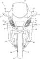
图2是本发明所涉及的车辆的主视图。Fig. 2 is a front view of the vehicle according to the present invention.
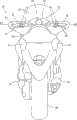
图3是本发明所涉及的车辆的后视图。Fig. 3 is a rear view of the vehicle according to the present invention.
图4是本发明所涉及的车辆的外观图。Fig. 4 is an external view of a vehicle according to the present invention.
图5是本发明所涉及的车辆的后部侧视图。Fig. 5 is a rear side view of the vehicle according to the present invention.
图6是表示本发明所涉及的同乘者座位的作用的作用说明图。Fig. 6 is an operation explanatory diagram showing the operation of the passenger seat according to the present invention.
图7是本发明所涉及的车辆的后部立体图。Fig. 7 is a rear perspective view of the vehicle according to the present invention.
图8是从后方观察所见的本发明所涉及的车辆的外观图。Fig. 8 is an external view of the vehicle according to the present invention seen from the rear.
图9是本发明所涉及的前照灯的主视图。Fig. 9 is a front view of the headlamp according to the present invention.
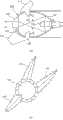
图10是本发明所涉及的前照灯的立体图。Fig. 10 is a perspective view of a headlamp according to the present invention.
图11是本发明所涉及的前照灯的侧视图。Fig. 11 is a side view of the headlamp according to the present invention.
图12是本发明所涉及的近光灯所具备的聚光型灯的剖视图。12 is a cross-sectional view of a spotlight included in the low beam headlight according to the present invention.
图13是本发明所涉及的远光灯的剖视图。Fig. 13 is a sectional view of the high beam according to the present invention.
图14是本发明所涉及的远光灯的主要部分的分解立体图。Fig. 14 is an exploded perspective view of main parts of the high beam according to the present invention.
图15(a)、图15(b)是本发明所涉及的位置灯的说明图。Fig. 15(a) and Fig. 15(b) are explanatory diagrams of the position lamp according to the present invention.
图16(a)、图16(b)是表示本发明所涉及的导光体作用的作用说明图。Fig. 16(a) and Fig. 16(b) are operation explanatory diagrams showing the operation of the light guide body according to the present invention.
图17(a)、图17(b)是表示本发明所涉及的位置灯作用的作用说明图。Fig. 17(a) and Fig. 17(b) are operation explanatory diagrams showing the operation of the position lamp according to the present invention.
[符号说明][Symbol Description]
10:车辆 13、14:前照灯10:
101:近光灯 102:远光灯101: low beam 102: high beam
103:位置灯 107、108:聚光型灯103: Position light 107, 108: Spotlight
111~113:导光体 120:LED111~113: light guide body 120: LED
131:外壳(副外壳) 142、146:内侧导光部131: Shell (sub-shell) 142, 146: Inner light guide
143:147、外侧导光部 148:前部角部143: 147, outer light guide 148: front corner
161:导光体161: light guide
具体实施方式Detailed ways
下面,基于附图对本发明的优选实施例进行说明。另外,应该沿着附图标记的阅读方向观察附图。Next, preferred embodiments of the present invention will be described based on the drawings. Furthermore, the drawings should be viewed along the reading direction of the reference numerals.
图1是采用本发明涉及的前照灯结构的车辆的侧视图,车辆10是小型摩托车,其结构如下:在构成车身罩11前部的前罩12上配置左、右一对前照灯13、14(图中只表示了靠近观察者一侧的附图标记13)以及左、右一对前转向灯16、17(图中只表示了靠近观察者一侧的附图标记16),在构成车身罩11后部的后部罩部件18上配置左、右一对后组合灯21、22(图中只表示了靠近观察者一侧的附图标记21),前照灯13、14,前转向灯16、17以及后组合灯21、22都以LED(发光二极管)作为光源。Fig. 1 is the side view of the vehicle that adopts the headlight structure related to the present invention, and
图中,31表示设置在前罩12上部的挡风玻璃,32表示操纵手柄,33表示由操纵手柄32操控的前叉,34表示安装在前叉33下端部的前轮,36表示前轮用盘形闸,37表示驾驶者脚踏的踏板,41表示双人座,42、42(图中只表示了靠近观察者一侧的附图标记42)表示配置在后部罩部件18内侧的左、右一对扶手杆,43、43(图中只表示了靠近观察者一侧的附图标记43)表示用于插入握住扶手杆42的手的开口部,44表示设置在车身框架(未图示)上的枢轴,45表示以可自由摆动的方式安装在枢轴44上的摆臂,46表示安装在摆臂45后端部上的后轮,47表示从动力单元(未图示)侧向后轮46传递动力的驱动轴,48表示后轮用盘形闸,51表示覆盖后轮46上方的后挡泥板,52表示支脚。Among the figure, 31 represents the windshield that is arranged on the top of the
图2是本发明涉及的车辆的主视图,车辆10的前照灯13、14是配置在开口61左、右的部分,该开口61设置于前罩12的中央,前转向灯16、17是位于前照灯13、14的上方位置且配置在侧方突出部62、63上的部分,该侧方突出部62、63设置于前罩12的左、右。Fig. 2 is the front view of the vehicle that the present invention relates to, and the
图中,66表示配置在前罩12下方且构成车身罩11的前侧罩,67表示在前侧罩66的前部打开的开口。In the figure, 66 denotes a front side cover disposed under the
所述开口61、67是用于使行驶时的气流流入车身罩11内的部分,行驶时流入的气流例如可以促进动力装置散热。The
图3是本发明涉及的车辆的后视图,在挡风玻璃31的后方且在操纵手柄32的前方设置有由仪表盘71以及EL(Electro-Luminescence)显示器72构成的显示装置73,设置在操纵手柄32左、右的把手74、76的前侧被所述侧方突出部62、63覆盖,在后部罩部件18的左、右配置后组合灯21、22。Fig. 3 is the rear view of the vehicle that the present invention relates to, the
后组合灯21,22他们都起到尾灯、停车灯以及后转向灯的作用。The
图中,81表示离合器分离杆,82表示前制动杆,83表示排气装置的消音器。In the figure, 81 denotes a clutch release lever, 82 denotes a front brake lever, and 83 denotes a muffler of an exhaust device.
接下来,对所述车辆10的详细结构进行说明。Next, a detailed structure of the
图4是本发明涉及的车辆的外观图,覆盖车辆10的一部分的车身罩11是由:兼作外罩部件的,并安装在车身框架(未图示)上覆盖其从前部到后部部分的主体部罩部件202;设置在驾驶者上、下车时让腿通过的腿通过空间下方的腿通过部罩部件203;以及设置在主体部罩部件202的后部上方并覆盖双人座41下方的后部罩部件18构成。Fig. 4 is the exterior view of the vehicle that the present invention relates to, and the vehicle body cover 11 that covers a part of
因为将后部罩部件18的表面18a和主体部罩部件202的后部202c的表面202a以从侧面看圆滑连接的方式形成,所以在关闭双人座41的时候,也可以使后部罩部件18和主体部罩部件202的后部202c具有整体感,可以将其视为车辆整体的座位外罩206。Because the
因此,可以将后部罩部件18看成上部座位外罩207,可以将主体部罩部件202的后部202c看成下部座位外罩208。Therefore, the
在此,211表示覆盖前叉33的滑动部的倾斜挡板,212表示覆盖驱动轴47(参照图1)的驱动轴罩,213表示前轮34的车轴,214、216表示设置在变速踏板的前端部及后端部上的足踏部,217表示后轮46的车轴,218表示连结驱动轴47(参照图1)与后轮46的驱动箱。Here, 211 denotes an inclined baffle that covers the sliding portion of the
图5是本发明涉及的车辆的后部侧视图,双人座41的结构可以分成驾驶者用座位221和同乘者用座位222,同乘者用座位222的结构特征在于:其与驾驶者用座位221各自独立,且可开可闭。Fig. 5 is the rear side view of the vehicle that the present invention relates to, and the structure of the
另外,设置在车身后部的左、右后组合灯21、22(图中只表示了靠近观察者一侧的附图标记21),配置在开口部43、43(图示的只是靠近观察者一侧的附图标记43)的后方,该开口部43、43设置在上部座位外罩207与下部座位外罩208之间。In addition, the left and right
一般来说,在后外罩上设置凹部,将该后组合灯收纳在该凹部之内。因此,后罩形状复杂且价格高。Generally, a recess is provided in the rear cover, and the rear combination lamp is accommodated in the recess. Therefore, the shape of the rear cover is complicated and the price is high.
就这一点来说,在本发明中,由于将后组合灯21、22设置在开口部43内,因此没有必要在座位外罩206上设置凹部,即便设置凹部,浅的凹部也就足以。其结果是,座位外罩206形状变得简单,能够降低包括座位外罩206在内的车身罩11的制造费用。In this regard, in the present invention, since the
接下来,对上述同乘者用座位222的作用进行说明。Next, the function of the above-mentioned
图6是表示本发明涉及的同乘者座位的作用的作用说明图,同乘者用座位222与驾驶者用座位221相对独立,并可通过合页部224可开可闭。6 is an explanatory diagram showing the function of the passenger seat according to the present invention. The
相反,如果由驾驶者用座位与同乘者用座位连接的一体型的双人座构成双人座41,那么该双人座41就会变得形状大且重量沉。On the contrary, if the
因为这一点,本发明采用同乘者用座位222与驾驶者用座位221相分离的双人座41。Because of this, the present invention adopts the
由于同乘者用座位222必然变得小型且轻量,因此其开闭就会变得非常容易。Since the
图7是本发明涉及的车辆的后部立体图(同乘者用座位222打开的状态),车辆10的后部具有:用于收纳物品而设在车身后部的收纳部231,以可开闭的方式覆盖该收纳部231的同乘者用座位222,构成覆盖该同乘者用座位222下方的座位外罩的一部分的下部座位外罩208,以及设在车身框架后部供乘客手握的扶手杆42,42。Fig. 7 is the rear perspective view of the vehicle related to the present invention (with the
另外在本实施例中,收纳部231能够收纳2个头盔。In addition, in this embodiment, the
图8是从后方观察所见的本发明涉及的车辆的外观图,在座位外罩206的后端部206b处具有用于开闭同乘者用座位222的开闭开关241。FIG. 8 is an external view of the vehicle according to the present invention seen from the rear, and an open/close switch 241 for opening and closing the
由于将用于开闭同乘者用座位222的开闭开关241设置在了座位外罩206的后端部206b处,因此,能够从车辆10的两侧对同乘者用座位222进行开闭操作。这样一来,能够提高开闭同乘者用座位222时的操作性。Since the open/close switch 241 for opening and closing the
图9是本发明涉及的前照灯的主视图,前照灯13由:设置在上部的近光灯101,设置在该近光灯101下方的远光灯102,设置在这些近光灯101和远光灯102周围的位置灯103(详情后述),支承并收纳这些灯的外壳104以及安装在该外壳104前部的透明透镜105构成。Fig. 9 is the front view of the headlight that the present invention relates to, the
近光灯101由多个聚光型灯107构成,远光灯102由一个聚光型灯108构成。The
图10是本发明涉及的前照灯的立体图,远光灯102是一种在侧壁109上附设有3个导光体111~113的灯,在远光灯102点亮时利用其一部分光使导光体111~113发光。Fig. 10 is a perspective view of a headlight according to the present invention. The
图11是本发明涉及的前照灯的侧视图,其中,使远光灯102沿着透镜105的倾斜方向相对近光灯101向车辆前方突出,使得从侧面能够看到近光灯101的一部分以及远光灯102的一部分,从而提高外观美感。11 is a side view of the headlamp according to the present invention, wherein the
图12是本发明涉及的近光灯所具备的聚光型灯沿垂直方向剖切的剖视图。Fig. 12 is a cross-sectional view taken along a vertical direction of the spotlight included in the low beam headlight according to the present invention.
聚光型灯107由:设置在外壳104(参照图9)上的副外壳116;配置在该副外壳116内的反射器117;安装在该反射器117后部中央的支承部118;安装在该支承部118前部的LED 120;在该LED 120的前方且安装在副外壳116前端的凸透镜121以及用于实现防止令对面车辆的驾驶者感到眩目的配光的遮光板(未图示)构成,由于该聚光型灯107具有椭圆形或者组合椭圆形反射面的反射器117以及凸透镜121,体积小且聚光性高,因此能够照亮远处。另外,123、124为向LED 120供给电力的导线。The
近光灯101(参照图9)通过使用多个(实施例中为4个)上述聚光型灯107,能够照亮车辆前方广阔的范围。The low beam 101 (see FIG. 9 ) can illuminate a wide area in front of the vehicle by using a plurality of (four in the embodiment) spotlights 107 described above.
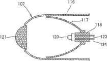
图13是本发明涉及的远光灯的大体沿垂直方向剖切的剖视图。Fig. 13 is a sectional view of the high beam lamp according to the present invention cut along the substantially vertical direction.
远光灯102由:设置在外壳104(参照图9)上的副外壳131;配置在副外壳131内的反射器132;安装在该反射器132后部中央且作为光源的卤素电灯泡133;在该卤素电灯泡133的前方且安装在副外壳131前端的凸透镜134以及用于实现防止令对面车辆的驾驶者感到眩目的配光的遮光板(未图示)构成,在副外壳131上附设有透明导光体111~113(图中只标出了附图标记111,113)。另外,136、136是卤素电灯泡133的端子,137是连接端子136、136的连接器,138、139是通过灯座137向卤素电灯泡133供给电力的导线。The
导光体111由插入副外壳131内的内侧导光部142以及与该内侧导光部142一体形成的外侧导光部143构成。The
导光体112(参照图9)的结构与导光体111相同,在此省略说明。The structure of the light guide body 112 (see FIG. 9 ) is the same as that of the
导光体113由插入副外壳131内的内侧导光部146以及与该内侧导光体146一体形成的外侧导光部147构成,使外侧导光部147的前部角部148一直延伸到凸透镜134下方。The
图14是本发明涉及的远光灯的主要部分的分解立体图,远光灯102具有副外壳131以及凸透镜134,副外壳131由安装在外壳104(参照图4)侧上的后部壳体151及结合在该后部壳体151前部的前部壳体152构成,在这些后部壳体151以及前部壳体152之间均安装有由导光体111、导光体112组合成一体的导光体组装件154以及导光体113。Fig. 14 is an exploded perspective view of main parts of the high-beam lamp related to the present invention, the high-
导光体111及导光体112的内侧导光部142构成环的一部分。The
图15(a)以及图15(b)是本发明涉及的位置灯的说明图。Fig. 15(a) and Fig. 15(b) are explanatory diagrams of the position lamp according to the present invention.
图15(a)是位置灯103的主视图,在前照灯13的除了近光灯101和远光灯102之外的部分上配置丙烯制的导光体161,在该导光体161的内侧配置多个LED 162,由此构成位置灯103。在图中,导光体161的轮廓线用粗线表示。Fig. 15 (a) is a front view of the
位置灯103的作用是在傍晚或者夜间等时,针对车辆前方通报本车辆的存在及车辆的宽度,本发明涉及的位置灯103由于其发光面积大,从而能够进一步提高视觉辨认性。The role of the
图15(b)是位置灯103的大体沿垂直方向剖切的剖视图。FIG. 15( b ) is a cross-sectional view of the
导光体161容易发散光线,例如可以将其涂成乳白色。The
LED 162被安装在部分被形成为上下台阶状的外壳104的前表面104a上。The
接下来对上述前照灯13的导光体111~113的作用进行说明。Next, the functions of the light guides 111 to 113 of the above-mentioned
图16(a)以及图16(b)是表示本发明涉及的导光体作用的作用示意图。Fig. 16(a) and Fig. 16(b) are operational schematic diagrams showing the operation of the light guide according to the present invention.
在图16(a)中,使卤素电灯泡133点亮,从灯丝发出的光如图中箭头A、B所示,在反射器132发生反射接着在焦点聚光,之后通过凸透镜134折射射向车辆前方。In Fig. 16(a), the
卤素电灯泡133所发出的部分光线如箭头C所示,进入导光体111以及导光体112(未图示)的内侧导光部142内,使得导光体111以及导光体112发光。Part of the light emitted by the
另外,卤素电灯泡133所发出的部分光线如箭头D所示,进入导光体113的内侧导光部146内,使导光体113发光。并且,凸透镜134内的部分光线如箭头E所示,从导光体113的前部角部148进入导光体113内部,使得导光体113发光。这样一来,能够使得导光体113更亮的发光。In addition, part of the light emitted by the
由于使上述导光体111~113发光的光不同于照射车辆前方的光,所以能够可靠地保证远光灯102的亮度。Since the light used to emit light from the light guides 111 to 113 is different from the light irradiating the front of the vehicle, the brightness of the
图16(b)是从正面看到的导光体111~113发光状态的示意图。FIG. 16( b ) is a schematic view of the light-emitting state of the light guides 111 to 113 viewed from the front.
由于三根导光体111~113在明亮发光的凸透镜134周围隐约发光,所以能够在提高视觉辨认性的同时对其外观赋予新颖的印象。Since the three
接下来,对所述位置灯103的作用进行说明。Next, the function of the position light 103 will be described.
图17(a)以及图17(b)是表示本发明涉及的位置灯作用的作用示意图。Fig. 17(a) and Fig. 17(b) are operational schematic diagrams showing the operation of the position light according to the present invention.
在图17(a)中,点亮各LED 162,LED 162所发出的光通过导光体161发散,使导光体161发光。In Fig. 17(a), each
图17(b)表示位置灯103的发光状态(图中交叉影线部分为发光部分)。由于除了近光灯101和远光灯102之外,前照灯13的大面积几乎同样发光,因此,能够更加提高视觉辨认性。Fig. 17(b) shows the light-emitting state of the position lamp 103 (the cross-hatched part in the figure is the light-emitting part). Since the large area of the
如上述对图2、图9以及图12所作的说明那样,在具有以LED 120为光源的前照灯13、14的车辆10中,本发明的第1特征在于:在近光灯101上具有多个以LED 120为光源的、作为第1聚光型灯的聚光型灯107,在远光灯102上至少具有一个作为第2聚光型灯的聚光型灯108。2, FIG. 9 and FIG. 12 as described above, in the
通过聚光型灯107,能够将LED 120所发出的光聚集到小范围内,照亮距车辆前方较远的位置,而且,通过设置多个聚光型灯107能够照射到车辆前方的广阔范围。Through the
本发明的第2特征在于:在远光灯102的外壳104上具有多个将光源所发出的光中的一部分引导至外部的导光体111~113。The second characteristic of the present invention is that the
使导光体111~113发光,能够更进一步提高前照灯13,14的视觉辨认性,另外,通过导光体111~113的外观设计能够提高其外观美感。By making the light guides 111 to 113 emit light, the visibility of the
本发明的第3特征在于:将近光灯101配置在上方,将远光灯102配置在近光灯的下方。The third feature of the present invention is that the
通过将平时亮的近光灯101配置在上方,能够提高前照灯13、14的视觉辨认性,另外,也能照射到更广阔的路面。By arranging the normally bright
如图2以及图15(a)、图15(b)所示,本发明的第4特征在于:在前照灯13、14内设置有由多个LED 162以及设置在这些LED162前方的平板状导光体161构成的位置灯103。As shown in Fig. 2 and Fig. 15 (a), Fig. 15 (b), the 4th characteristic of the present invention is: be provided with in the
利用导光体161使多个LED 162所发出的光发散并能够使得整个导光体161发光,能够提高视觉辨认性。另外前照灯13、14能够具备新颖的外观。Utilizing the
如图13所示,本发明的第5特征在于:导光体111~113包括设置在副外壳131内的内侧导光部142、142、146(图中只表示了一侧的附图标记142)以及与该内侧导光部142、142、146一体形成的外侧导光部143、143、147(图中只表示了一侧的附图标记143)。As shown in FIG. 13 , the fifth feature of the present invention is that the light guides 111 to 113 include inner light guides 142, 142, 146 arranged in the sub-housing 131 (only one side of the
这样一来,可以将作为副外壳131内的光源的卤素电灯泡133所发出的光顺利地从内侧导光部142、142、146引导至外侧导光部143、143、147,使外侧导光部143、143、147有效的发光。In this way, the light emitted by the
如图9以及图13所示,本发明的第6特征在于:将外侧导光部143、143、147用作为远光灯102的支架部。As shown in FIGS. 9 and 13 , the sixth feature of the present invention is that the outer light guides 143 , 143 , and 147 are used as the bracket portion of the
这样一来,该支架部能够支承远光灯102,又由于导光体111~113兼作支架部之用,所以没有必要特别设置远光灯102的支承支架,能够减少部件数量从而降低成本。In this way, the bracket part can support the
如图13以及图16所示,本发明的第7特征在于:在外侧导光部143、143、147上具有对远光灯102的前方照射光进行导光的前部角部148。As shown in FIGS. 13 and 16 , the seventh feature of the present invention is that the outer light guides 143 , 143 , 147 have
这样一来,可以与从副外壳131内引导出的光共同作为前方照射光使外侧导光部143、143、147发光,可以使外侧导光部143、143、147更加明亮的发光。In this way, the outer light guides 143 , 143 , 147 can emit light together with the light guided from the sub-casing 131 as forward light, and the outer light guides 143 , 143 , 147 can be made to emit light more brightly.
如图2所示,本发明的第8特征在于:将前照灯13、14的后上方制成椭圆形,并将近光灯101设置在其外侧上方部,将远光灯102设置在内侧下方部。As shown in Fig. 2, the 8th feature of the present invention is: make the rear top of
这样一来,能够将近光灯101配置在更高且更靠近车辆宽度方向外侧的位置上,能够进一步提高近光灯101的视觉辨认性。In this way, the
另外,如图13所示,虽然在本实施例中,将卤素电灯泡133作为远光灯102的光源使用,但是并不局限于此,也可以使用LED或者高辉度放电灯(HID灯)。该LED优选辉度高于近光灯用LED 120(参照图12)的LED。In addition, as shown in FIG. 13, although in the present embodiment, a
[产业上的可利用性][industrial availability]
本发明所涉及的前照灯结构适宜用于两轮摩托车。The headlamp structure involved in the present invention is suitable for two-wheeled motorcycles.
Claims (6)
Applications Claiming Priority (2)
| Application Number | Priority Date | Filing Date | Title |
|---|---|---|---|
| JP2005293059AJP4563912B2 (en) | 2005-10-05 | 2005-10-05 | Vehicle headlamp structure |
| JP293059/2005 | 2005-10-05 |
Publications (2)
| Publication Number | Publication Date |
|---|---|
| CN1945105A CN1945105A (en) | 2007-04-11 |
| CN100570206Ctrue CN100570206C (en) | 2009-12-16 |
Family
ID=38029949
Family Applications (1)
| Application Number | Title | Priority Date | Filing Date |
|---|---|---|---|
| CNB2006101418161AExpired - Fee RelatedCN100570206C (en) | 2005-10-05 | 2006-09-30 | Vehicle headlight structure |
Country Status (3)
| Country | Link |
|---|---|
| JP (1) | JP4563912B2 (en) |
| CN (1) | CN100570206C (en) |
| TW (1) | TW200730762A (en) |
Cited By (1)
| Publication number | Priority date | Publication date | Assignee | Title |
|---|---|---|---|---|
| CN101858548A (en)* | 2010-03-23 | 2010-10-13 | 重庆科鹰电气有限公司 | LED luminescent unit and motorcycle LED headlamp light source thereby |
Families Citing this family (19)
| Publication number | Priority date | Publication date | Assignee | Title |
|---|---|---|---|---|
| JP5151316B2 (en)* | 2007-08-28 | 2013-02-27 | 日産自動車株式会社 | Vehicle lamp |
| JP5238396B2 (en)* | 2007-10-29 | 2013-07-17 | Piaa株式会社 | Vehicle bulb and vehicle lamp |
| CN101825251A (en)* | 2009-03-02 | 2010-09-08 | 光阳工业股份有限公司 | Headlight device of motorcycle |
| CN101832501A (en)* | 2009-07-22 | 2010-09-15 | 苏州睿昕汽车配件有限公司 | Vehicle headlamp with LED light source |
| TWI396638B (en)* | 2010-03-18 | 2013-05-21 | 私立中原大學 | Lamp structure |
| WO2011116635A1 (en)* | 2010-03-23 | 2011-09-29 | 重庆科鹰电气有限公司 | Led lighting unit and led headlamp formed by the same |
| CN102175006A (en)* | 2010-12-14 | 2011-09-07 | 广州大学 | Novel motorcycle LED headlamp |
| JP5673510B2 (en) | 2011-11-29 | 2015-02-18 | 豊田合成株式会社 | Vehicle headlamp |
| US8820992B2 (en)* | 2012-05-23 | 2014-09-02 | Ford Global Technologies, Llc | Automotive headlamp assembly |
| CN102691958A (en)* | 2012-05-29 | 2012-09-26 | 江苏德厚机电有限公司 | LED locomotive headlamp |
| US20150219300A1 (en)* | 2012-08-28 | 2015-08-06 | Mitsubishi Electric Corporation | Light source for head light and head light |
| JP6116935B2 (en)* | 2013-02-28 | 2017-04-19 | 本田技研工業株式会社 | Motorcycle headlamp device |
| JP6297418B2 (en)* | 2014-05-30 | 2018-03-20 | ヤンマー株式会社 | Tractor headlight device |
| CN106152012B (en)* | 2015-04-21 | 2019-01-18 | 唐强 | LED automobile driving lamp |
| CN106813181A (en)* | 2015-12-01 | 2017-06-09 | 认知控管株式会社 | The backlight direction-changing device of vehicle head lamp |
| WO2020029022A1 (en)* | 2018-08-06 | 2020-02-13 | 炼马机电(东莞)有限公司 | Backlight |
| JP6885982B2 (en) | 2019-04-05 | 2021-06-16 | 本田技研工業株式会社 | Headlight structure of saddle-riding vehicle |
| JP7157721B2 (en)* | 2019-09-30 | 2022-10-20 | 本田技研工業株式会社 | headlight device |
| CN115666298A (en)* | 2020-07-09 | 2023-01-31 | 日本烟草产业株式会社 | Main unit of aerosol generating device, aerosol generating device, and non-combustion inhaler |
Citations (4)
| Publication number | Priority date | Publication date | Assignee | Title |
|---|---|---|---|---|
| CN2499695Y (en)* | 2001-08-23 | 2002-07-10 | 李森墉 | A lampshade light guide device |
| CN1450300A (en)* | 2002-04-08 | 2003-10-22 | 株式会社猫眼 | Head lamp for bicycle |
| CN1456472A (en)* | 2002-05-09 | 2003-11-19 | 本田技研工业株式会社 | Headlight device on motor cycle |
| TWM270107U (en)* | 2004-12-21 | 2005-07-11 | Sanyang Industry Co Ltd | A motorcycle headlight device |
Family Cites Families (5)
| Publication number | Priority date | Publication date | Assignee | Title |
|---|---|---|---|---|
| JPH01100304U (en)* | 1987-12-24 | 1989-07-05 | ||
| JP3217209B2 (en)* | 1994-05-18 | 2001-10-09 | 株式会社小糸製作所 | Lens for vehicle lighting |
| JP4565603B2 (en)* | 2001-09-07 | 2010-10-20 | スタンレー電気株式会社 | Vehicle headlamp |
| JP4030898B2 (en)* | 2002-03-12 | 2008-01-09 | 株式会社小糸製作所 | Vehicle headlamp |
| JP4102240B2 (en)* | 2003-04-08 | 2008-06-18 | 株式会社小糸製作所 | Vehicle headlamp |
- 2005
- 2005-10-05JPJP2005293059Apatent/JP4563912B2/ennot_activeExpired - Fee Related
- 2006
- 2006-09-30CNCNB2006101418161Apatent/CN100570206C/ennot_activeExpired - Fee Related
- 2006-10-02TWTW095136529Apatent/TW200730762A/ennot_activeIP Right Cessation
Patent Citations (4)
| Publication number | Priority date | Publication date | Assignee | Title |
|---|---|---|---|---|
| CN2499695Y (en)* | 2001-08-23 | 2002-07-10 | 李森墉 | A lampshade light guide device |
| CN1450300A (en)* | 2002-04-08 | 2003-10-22 | 株式会社猫眼 | Head lamp for bicycle |
| CN1456472A (en)* | 2002-05-09 | 2003-11-19 | 本田技研工业株式会社 | Headlight device on motor cycle |
| TWM270107U (en)* | 2004-12-21 | 2005-07-11 | Sanyang Industry Co Ltd | A motorcycle headlight device |
Cited By (1)
| Publication number | Priority date | Publication date | Assignee | Title |
|---|---|---|---|---|
| CN101858548A (en)* | 2010-03-23 | 2010-10-13 | 重庆科鹰电气有限公司 | LED luminescent unit and motorcycle LED headlamp light source thereby |
Also Published As
| Publication number | Publication date |
|---|---|
| TW200730762A (en) | 2007-08-16 |
| JP4563912B2 (en) | 2010-10-20 |
| TWI305566B (en) | 2009-01-21 |
| CN1945105A (en) | 2007-04-11 |
| JP2007103212A (en) | 2007-04-19 |
Similar Documents
| Publication | Publication Date | Title |
|---|---|---|
| CN100570206C (en) | Vehicle headlight structure | |
| US8118460B2 (en) | Motorcycle headlamp | |
| CN101457892A (en) | Vehicle lamp assembly | |
| US9248776B2 (en) | Vehicular light unit with multiple light sources | |
| US10173576B2 (en) | Vehicle lighting structure | |
| CN1945106A (en) | Turn signal lamp for a vehicle | |
| JP2010040322A (en) | Lighting fixture for vehicle | |
| CN107429893A (en) | Headlamp | |
| CN104006341B (en) | Illumination apparatus | |
| TWI521164B (en) | Vehicle headlight construction | |
| CN107429898B (en) | headlamp | |
| JP2009158409A (en) | Vehicle lighting structure | |
| CN108372896A (en) | The lamp device of vehicle | |
| CN100572898C (en) | Two-wheeled rear combination lamp structure | |
| JP2004210236A (en) | Outer mirror housing and outer mirror cover | |
| JP6192238B2 (en) | Motorcycle | |
| CN202813159U (en) | Headlight | |
| JP2004193021A (en) | Vehicle lighting | |
| CN100537300C (en) | Automotive headlight assembly with one main light source and one driving direction indicator | |
| JP6885982B2 (en) | Headlight structure of saddle-riding vehicle | |
| TWI438113B (en) | Straddle type vehicle | |
| CN100572896C (en) | lamp | |
| TWI358366B (en) | ||
| CN100462622C (en) | vehicle lights | |
| CN222291891U (en) | motorcycle |
Legal Events
| Date | Code | Title | Description |
|---|---|---|---|
| C06 | Publication | ||
| PB01 | Publication | ||
| C10 | Entry into substantive examination | ||
| SE01 | Entry into force of request for substantive examination | ||
| C14 | Grant of patent or utility model | ||
| GR01 | Patent grant | ||
| CF01 | Termination of patent right due to non-payment of annual fee | ||
| CF01 | Termination of patent right due to non-payment of annual fee | Granted publication date:20091216 |