CN100570115C - Easy-to-modify electronically controlled door lock system - Google Patents
Easy-to-modify electronically controlled door lock systemDownload PDFInfo
- Publication number
- CN100570115C CN100570115CCNB2005800083978ACN200580008397ACN100570115CCN 100570115 CCN100570115 CCN 100570115CCN B2005800083978 ACNB2005800083978 ACN B2005800083978ACN 200580008397 ACN200580008397 ACN 200580008397ACN 100570115 CCN100570115 CCN 100570115C
- Authority
- CN
- China
- Prior art keywords
- door lock
- function
- door
- expanding device
- lock
- Prior art date
- Legal status (The legal status is an assumption and is not a legal conclusion. Google has not performed a legal analysis and makes no representation as to the accuracy of the status listed.)
- Expired - Lifetime
Links
- 230000004044responseEffects0.000claimsabstractdescription6
- 230000006870functionEffects0.000claimsdescription127
- 238000004891communicationMethods0.000claimsdescription15
- 238000012545processingMethods0.000claimsdescription14
- 238000012544monitoring processMethods0.000claims1
- 230000008859changeEffects0.000abstractdescription2
- 238000010295mobile communicationMethods0.000description16
- 230000003993interactionEffects0.000description8
- 238000005516engineering processMethods0.000description7
- 238000001514detection methodMethods0.000description6
- 238000000034methodMethods0.000description6
- 230000008569processEffects0.000description5
- 230000002265preventionEffects0.000description4
- 230000002452interceptive effectEffects0.000description3
- 239000002184metalSubstances0.000description2
- 239000004065semiconductorSubstances0.000description2
- 238000005406washingMethods0.000description2
- 238000013459approachMethods0.000description1
- 230000000295complement effectEffects0.000description1
- 238000011161developmentMethods0.000description1
- 238000010586diagramMethods0.000description1
- 230000006872improvementEffects0.000description1
- 238000004519manufacturing processMethods0.000description1
- 229910044991metal oxideInorganic materials0.000description1
- 150000004706metal oxidesChemical class0.000description1
- 238000012986modificationMethods0.000description1
- 230000004048modificationEffects0.000description1
- 230000006855networkingEffects0.000description1
Images


Classifications
- E—FIXED CONSTRUCTIONS
- E05—LOCKS; KEYS; WINDOW OR DOOR FITTINGS; SAFES
- E05B—LOCKS; ACCESSORIES THEREFOR; HANDCUFFS
- E05B47/00—Operating or controlling locks or other fastening devices by electric or magnetic means
- A—HUMAN NECESSITIES
- A63—SPORTS; GAMES; AMUSEMENTS
- A63F—CARD, BOARD, OR ROULETTE GAMES; INDOOR GAMES USING SMALL MOVING PLAYING BODIES; VIDEO GAMES; GAMES NOT OTHERWISE PROVIDED FOR
- A63F13/00—Video games, i.e. games using an electronically generated display having two or more dimensions
- A63F13/90—Constructional details or arrangements of video game devices not provided for in groups A63F13/20 or A63F13/25, e.g. housing, wiring, connections or cabinets
- E—FIXED CONSTRUCTIONS
- E05—LOCKS; KEYS; WINDOW OR DOOR FITTINGS; SAFES
- E05F—DEVICES FOR MOVING WINGS INTO OPEN OR CLOSED POSITION; CHECKS FOR WINGS; WING FITTINGS NOT OTHERWISE PROVIDED FOR, CONCERNED WITH THE FUNCTIONING OF THE WING
- E05F5/00—Braking devices, e.g. checks; Stops; Buffers
- E05F5/003—Braking devices, e.g. checks; Stops; Buffers for sliding wings
- G—PHYSICS
- G07—CHECKING-DEVICES
- G07C—TIME OR ATTENDANCE REGISTERS; REGISTERING OR INDICATING THE WORKING OF MACHINES; GENERATING RANDOM NUMBERS; VOTING OR LOTTERY APPARATUS; ARRANGEMENTS, SYSTEMS OR APPARATUS FOR CHECKING NOT PROVIDED FOR ELSEWHERE
- G07C9/00—Individual registration on entry or exit
- G07C9/00174—Electronically operated locks; Circuits therefor; Nonmechanical keys therefor, e.g. passive or active electrical keys or other data carriers without mechanical keys
- G07C9/00571—Electronically operated locks; Circuits therefor; Nonmechanical keys therefor, e.g. passive or active electrical keys or other data carriers without mechanical keys operated by interacting with a central unit
- G—PHYSICS
- G07—CHECKING-DEVICES
- G07C—TIME OR ATTENDANCE REGISTERS; REGISTERING OR INDICATING THE WORKING OF MACHINES; GENERATING RANDOM NUMBERS; VOTING OR LOTTERY APPARATUS; ARRANGEMENTS, SYSTEMS OR APPARATUS FOR CHECKING NOT PROVIDED FOR ELSEWHERE
- G07C9/00—Individual registration on entry or exit
- G07C9/00174—Electronically operated locks; Circuits therefor; Nonmechanical keys therefor, e.g. passive or active electrical keys or other data carriers without mechanical keys
- G07C9/00896—Electronically operated locks; Circuits therefor; Nonmechanical keys therefor, e.g. passive or active electrical keys or other data carriers without mechanical keys specially adapted for particular uses
- G07C9/00904—Electronically operated locks; Circuits therefor; Nonmechanical keys therefor, e.g. passive or active electrical keys or other data carriers without mechanical keys specially adapted for particular uses for hotels, motels, office buildings or the like
- G—PHYSICS
- G07—CHECKING-DEVICES
- G07C—TIME OR ATTENDANCE REGISTERS; REGISTERING OR INDICATING THE WORKING OF MACHINES; GENERATING RANDOM NUMBERS; VOTING OR LOTTERY APPARATUS; ARRANGEMENTS, SYSTEMS OR APPARATUS FOR CHECKING NOT PROVIDED FOR ELSEWHERE
- G07C9/00—Individual registration on entry or exit
- G07C9/20—Individual registration on entry or exit involving the use of a pass
- G07C9/27—Individual registration on entry or exit involving the use of a pass with central registration
- G—PHYSICS
- G07—CHECKING-DEVICES
- G07F—COIN-FREED OR LIKE APPARATUS
- G07F17/00—Coin-freed apparatus for hiring articles; Coin-freed facilities or services
- G07F17/32—Coin-freed apparatus for hiring articles; Coin-freed facilities or services for games, toys, sports, or amusements
- E—FIXED CONSTRUCTIONS
- E05—LOCKS; KEYS; WINDOW OR DOOR FITTINGS; SAFES
- E05B—LOCKS; ACCESSORIES THEREFOR; HANDCUFFS
- E05B47/00—Operating or controlling locks or other fastening devices by electric or magnetic means
- E05B2047/0091—Retrofittable electric locks, e.g. an electric module can be attached to an existing manual lock
- E—FIXED CONSTRUCTIONS
- E05—LOCKS; KEYS; WINDOW OR DOOR FITTINGS; SAFES
- E05B—LOCKS; ACCESSORIES THEREFOR; HANDCUFFS
- E05B47/00—Operating or controlling locks or other fastening devices by electric or magnetic means
- E05B47/0001—Operating or controlling locks or other fastening devices by electric or magnetic means with electric actuators; Constructional features thereof
- E05B47/0012—Operating or controlling locks or other fastening devices by electric or magnetic means with electric actuators; Constructional features thereof with rotary electromotors
- Y—GENERAL TAGGING OF NEW TECHNOLOGICAL DEVELOPMENTS; GENERAL TAGGING OF CROSS-SECTIONAL TECHNOLOGIES SPANNING OVER SEVERAL SECTIONS OF THE IPC; TECHNICAL SUBJECTS COVERED BY FORMER USPC CROSS-REFERENCE ART COLLECTIONS [XRACs] AND DIGESTS
- Y10—TECHNICAL SUBJECTS COVERED BY FORMER USPC
- Y10T—TECHNICAL SUBJECTS COVERED BY FORMER US CLASSIFICATION
- Y10T70/00—Locks
- Y10T70/50—Special application
- Y10T70/5093—For closures
- Y10T70/554—Cover, lid, cap, encasing shield
- Y10T70/5562—Removable
- Y—GENERAL TAGGING OF NEW TECHNOLOGICAL DEVELOPMENTS; GENERAL TAGGING OF CROSS-SECTIONAL TECHNOLOGIES SPANNING OVER SEVERAL SECTIONS OF THE IPC; TECHNICAL SUBJECTS COVERED BY FORMER USPC CROSS-REFERENCE ART COLLECTIONS [XRACs] AND DIGESTS
- Y10—TECHNICAL SUBJECTS COVERED BY FORMER USPC
- Y10T—TECHNICAL SUBJECTS COVERED BY FORMER US CLASSIFICATION
- Y10T70/00—Locks
- Y10T70/70—Operating mechanism
- Y10T70/7006—Predetermined time interval controlled
- Y10T70/7028—Electric
- Y—GENERAL TAGGING OF NEW TECHNOLOGICAL DEVELOPMENTS; GENERAL TAGGING OF CROSS-SECTIONAL TECHNOLOGIES SPANNING OVER SEVERAL SECTIONS OF THE IPC; TECHNICAL SUBJECTS COVERED BY FORMER USPC CROSS-REFERENCE ART COLLECTIONS [XRACs] AND DIGESTS
- Y10—TECHNICAL SUBJECTS COVERED BY FORMER USPC
- Y10T—TECHNICAL SUBJECTS COVERED BY FORMER US CLASSIFICATION
- Y10T70/00—Locks
- Y10T70/70—Operating mechanism
- Y10T70/7051—Using a powered device [e.g., motor]
- Y10T70/7062—Electrical type [e.g., solenoid]
- Y10T70/7107—And alternately mechanically actuated by a key, dial, etc.
Landscapes
- Physics & Mathematics (AREA)
- General Physics & Mathematics (AREA)
- Engineering & Computer Science (AREA)
- Multimedia (AREA)
- Lock And Its Accessories (AREA)
Abstract
Description
Translated fromChinese技术领域technical field
本发明涉及一种电子控制门锁系统,尤其涉及一种能够根据需要方便地对门锁进行改进并因此通过使具有附加功能的功能扩展装置与具有预定固有功能的门锁可替换地连接而改进门锁性能的易于改进的电子控制门锁系统。The present invention relates to an electronically controlled door lock system, in particular to a system capable of conveniently improving the door lock according to needs and thus improving the door by connecting a function expansion device with additional functions with a door lock with predetermined inherent functions. Electronically controlled door lock system for easy improvement of lock performance.
背景技术Background technique
通过金属钥匙来锁门和开门的机械门锁主要应用于办公室、酒店和公寓等的门锁装置。然而,由于作为锁门和开门工具的金属钥匙的由于疏忽易被丢失或被不希望地复制的缺点导致传统的机械门锁的安全性能不佳。目前,针对传统机械门锁的缺点,多种门锁被使用,如使用磁卡型或聪明卡型的电子钥匙开门和锁门的门锁、通过输入密码开门和锁门的门锁等。此外,能通过对人体的特殊部分的固有特征的生物识别,如声音识别、指纹识别和面容识别等开门和锁门的门锁正在被积极研究和商品化。Mechanical door locks that lock and unlock doors with a metal key are mainly used in door locks for offices, hotels, and apartments. However, the security performance of traditional mechanical door locks is poor due to the disadvantage that the metal key used as a door locking and opening tool is easily lost due to inadvertence or copied undesirably. At present, in view of the shortcomings of traditional mechanical door locks, a variety of door locks are used, such as door locks that use magnetic card type or smart card type electronic keys to open and lock the door, and door locks that use passwords to open and lock the door. In addition, door locks that can open and lock doors through biometric identification of inherent characteristics of special parts of the human body, such as voice recognition, fingerprint recognition, and face recognition, are being actively researched and commercialized.
同时,以互联网和移动通讯为代表的信息通讯技术正在改变现代的生活模式。特别地,可使用互联网的个人电脑已经遍布几乎所有的家庭、学校和办公室,允许使用者通过网站获得信息、通过电子交易购买商品以及通过电子邮件交换消息。另外,通过移动通讯终端的使用,除声音呼叫定位移动通讯服务以外的各种服务如财务结算、家庭自动化、使用无线互联网等被提供。At the same time, information and communication technologies represented by the Internet and mobile communications are changing modern life patterns. In particular, Internet-enabled personal computers have been found in almost all homes, schools, and offices, allowing users to obtain information through websites, purchase goods through electronic transactions, and exchange messages through e-mail. In addition, through the use of mobile communication terminals, various services other than voice call location mobile communication services such as financial settlement, home automation, use of wireless Internet, etc. are provided.
在初始阶段,信息通讯技术如计算机、移动通讯、广播等根据它们的使用目的分别发展。如今,这些技术有集中发展的趋势。信息通讯技术集中发展的代表例可能是家庭网络。家用电器开始显现出它们能与互联网和/或移动通讯进行交互从而构成家庭网络。换句话说,照惯例,使用者只能在屋内直接操作电视接收器、洗衣机等,但现在,即使在屋外,使用者也可以通过使用与互联网连接的移动通讯终端控制各种家用电器如电视接收器、洗衣机、照明设备和烤箱等。In the initial stage, information and communication technologies such as computers, mobile communications, broadcasting, etc. were developed according to their usage purposes. Today, there is a tendency for these technologies to develop intensively. A representative example of the intensive development of ICT may be the home network. Household appliances are beginning to show that they can interact with the Internet and/or mobile communications to form a home network. In other words, conventionally, users can only directly operate TV receivers, washing machines, etc. inside the house, but now, even outside the house, users can control various home appliances such as TV receivers by using mobile communication terminals connected to the Internet. Appliances, washing machines, lighting and ovens, etc.
同时,传统的门锁通常为只能执行由在它们制造过程中初步配备的硬件和软件设定的功能的单机类型。除非整个更换门锁,否则不可能扩展门锁功能,即使使用者希望享有如犯罪预防、火灾检测和家庭网络这样的附加功能。Meanwhile, conventional door locks are generally stand-alone types that can only perform functions set by hardware and software initially equipped in their manufacturing process. It is impossible to expand the door lock function without replacing the whole door lock, even if the user wishes to enjoy additional functions such as crime prevention, fire detection and home networking.
发明内容Contents of the invention
因此,本发明被用来解决上述现有技术固有的问题,本发明的目的是提供一种易于改进的、电子控制的门锁系统,其允许使用的门锁可以容易地和便宜地被改进,从而为门锁增加新的如犯罪预防、指纹识别、火灾检测以及与家庭网络交互的功能,因此不用更换整个门锁就能改变或扩展使用中的门锁的功能。Therefore, the present invention is made to solve the above-mentioned problems inherent in the prior art. It is an object of the present invention to provide an easily retrofittable, electronically controlled door locking system which allows the door locks used to be retrofitted easily and cheaply, Thereby adding new functions such as crime prevention, fingerprint identification, fire detection and interaction with home network to the door lock, so the function of the door lock in use can be changed or expanded without replacing the entire door lock.
为了达到上述和其它目的,本发明的易于改进的、电子控制的门锁系统包括:响应来自钥匙装置的输入信号的用于锁门和开门的门锁100,该门锁具有预定的固有功能;和具有除门锁的预定固有功能之外的附加功能并被可更换地连接至门锁100的功能扩展装置200,其中门锁100包括用于识别门锁钥匙装置的识别单元102,用于可分离地连接功能扩展装置200到门锁100的多用途接口装置110,用于控制功能扩展装置200的操作的多用途接口装置控制单元112,用于控制门锁100的全部操作的控制器单元104,以及用于促使门锁在控制器单元104的控制下执行锁和解锁功能的驱动单元114。In order to achieve the above and other objects, the easily modifiable, electronically controlled door lock system of the present invention includes: a
根据本发明的门锁系统使不更换正使用的门锁而容易地和便宜地增加使用者希望的功能,从而改变或扩展门锁的功能成为可能。The door lock system according to the present invention makes it possible to change or expand the functions of the door lock by easily and cheaply adding functions desired by the user without replacing the door lock being used.
附图说明Description of drawings
本发明的以上目的、其它特征及优点将通过结合附图对优选实施例的说明而变得更清楚,其中:The above purpose, other features and advantages of the present invention will become clearer through the description of preferred embodiments in conjunction with the accompanying drawings, wherein:
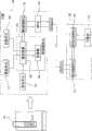
图1所示为根据本发明的易于改进的、电子控制的门锁系统的结构的方框图;Fig. 1 shows the block diagram that is easy to improve according to the structure of the electronically controlled door lock system of the present invention;
图2所示为通过功能扩展装置与家庭网络系统连接的门锁系统的视图;Figure 2 is a view of the door lock system connected to the home network system through the function expansion device;
图3所示为本发明的提供了具有照相功能的功能扩展装置的门锁系统的视图;Figure 3 shows the view of the door lock system provided with the function expansion device with camera function of the present invention;
图4所示为在根据本发明的门锁系统中为门锁安装新的功能扩展装置的初始过程的流程图。FIG. 4 is a flow chart showing the initial process of installing a new function expansion device for a door lock in the door lock system according to the present invention.
具体实施方式Detailed ways
现在,将结合附图对根据本发明的优选实施例的易于改进的、电子控制的门锁系统进行详细说明。在本发明下面的描述中,相同的附图标记即使在不同的附图中也表示相同的部件,为了简化,将省略重复的说明。Now, an easily modifiable, electronically controlled door lock system according to a preferred embodiment of the present invention will be described in detail with reference to the accompanying drawings. In the following description of the present invention, the same reference numerals denote the same components even in different drawings, and repeated descriptions will be omitted for simplicity.
参照图1,本发明的门锁系统包括:根据来自钥匙装置的输入信号锁门和开门并具有预定的固有功能的门锁100,和具有除门锁的预定固有功能之外的附加功能并可以被更换地连接至门锁100的功能扩展装置200。这里,术语“固有功能”是指内置于门锁的所有固有的功能,包括锁和解锁功能。“附加功能”将在后面说明。With reference to Fig. 1, the door lock system of the present invention comprises: according to the
门锁100包括:识别单元102、控制器单元104、多用途接口装置110、多用途接口装置控制单元112、驱动单元114和供电单元116。图中,多用途接口单元用“MPID”表示。The
控制器单元104被提供了具有串行和并行端口的微处理器106和存储用于驱动门锁100的程序、钥匙装置的检测信息和识别算法的存储器108。并且,控制器单元104与识别单元102、多用途接口装置110、多用途接口装置控制单元112、驱动单元114和供电单元116连接,并适合于控制门锁100的全部操作和功能扩展装置200。这里,术语“钥匙装置”表示能输入门锁100需要的锁和解锁的信号的所有装置,可以包括磁卡型电子钥匙、半导体棒钥匙、门锁100中的数字按钮等。The
另外,通过比较识别单元102检测的钥匙装置的识别信息与存储器108中存储的检测信息,控制器单元104适合于驱动识别算法并判断对应的钥匙装置是否合适。如果钥匙装置合适,控制器单元104产生和传输锁门和开门信号至驱动单元114。并且,控制器单元104控制通过多用途接口装置控制单元112与多用途接口装置连接的功能扩展装置200,或根据来自功能扩展装置200的信号驱动门锁100。In addition, by comparing the identification information of the key device detected by the
多用途接口装置110是用于适合地连接功能扩展装置200至门锁100的装置,更广义地,它包括如图1所示的销槽型连接器。如果使用者打算给当前使用的门锁100增加如照相功能、指纹识别功能、火灾检测功能、犯罪预防功能和家庭网络交互功能等单独的附加功能,他/她可以无需更换一个新的门锁100而只要将具有对应功能的功能扩展装置200连接至多用途接口装置110就可以扩展功能。The
多用途接口装置控制单元112是包括用于控制与多用途接口装置110连接的功能扩展装置200的算法,执行与控制器单元104和功能扩展装置200进行数据通讯的协议,以及各自用于处理数据通讯信号的编码器和解码器的电子电路。多用途接口装置控制单元112适合于通过如电压、频率、信号时间等电特性、如连接器的销式排列或形状的机械特性、如命令响应、通讯协议的逻辑特性等识别和控制与多用途接口装置110连接的功能扩展装置200。The multipurpose interface
驱动单元114包括一个或多个继电器驱动装置、螺线管驱动装置、伺服电动机、插锁等,所有这些未在图中表示。驱动单元114适合于驱动包括伺服电动机和插锁的负载以响应从控制器单元104输出的锁门和开门信号,使插锁执行锁和解锁的功能。这里,术语“插锁”是指机械地操作锁/开门的门锁连接组件。
供电单元116包括使用电池的内部供电和使用商业供电的外部供电。供电单元116用于提供操作识别单元102、控制器单元104、驱动单元114和功能扩展装置200的电力。The
现在,将要说明可更换地连接到门锁100的多用途接口装置110的功能扩展装置200。功能扩展装置200包括多用途接口装置连接单元202,子模块204和多用途接口装置信号处理单元206。Now, the
多用途接口装置连接单元202与门锁100的多用途接口装置110可分离地连接。子模块204是指用于执行将被扩展的功能例如,照相功能、指纹识别功能、火灾检测功能和家庭网络交互功能等除门锁100的固有功能外的硬件和/或软件。软件包括一组命令语言和用于控制上述硬件的操作系统程序。The multipurpose interface
如果功能扩展装置200与门锁100连接,那么门锁100的功能被扩展。例如,如果具有照相功能的功能扩展装置200与门锁100连接,那么门锁100的功能就以它可以给锁和解锁门锁100的人照相及存储所照的照片的方式被扩展。如果具有指纹识别功能的功能扩展装置200与门锁100连接,那么门锁100的功能以它可以通过指纹识别来识别使用者的方式被扩展。另外,如果具有家庭网络功能的功能扩展装置200与门锁100连接,那么门锁100的功能以它可以与家庭网络服务器(未示出)交互并具有在屋外控制门锁100的功能的方式被扩展。If the
多用途接口装置信号处理单元206是用于处理在功能扩展装置200与门锁100之间互相传输的电信号的装置,并包括,例如,用于对电信号进行编码的编码器(未示出)和用于对电信号进行解码的解码器(未示出)。The multipurpose interface device
如果门锁100的控制器单元104传输了用于控制功能扩展装置200的编码后的电信号,多用途接口装置信号处理单元206对传输的电信号进行解码并将该解码后的信号传输至子模快204。子模块204基于解码后的电信号控制功能扩展装置200的全部操作。相反,如果功能扩展装置200将用于控制门锁100操作的电信号传输至门锁100,多用途接口装置信号处理单元206对传输的电信号进行编码并将该编码后的信号传输至门锁100的控制器单元104。If the
图2所示为根据本发明的门锁系统的视图,其中门锁100通过功能扩展装置200与家庭网络系统连接。FIG. 2 is a view of the door lock system according to the present invention, wherein the
根据本发明的门锁系统构成了家庭网络系统的一部分。换句话说,家庭网络系统包括门锁100、功能扩展装置200、家庭网络服务器300、家庭网络交互装置302、移动通讯网络304、移动通讯终端306、互联网308和计算机310。The door lock system according to the invention forms part of a home network system. In other words, the home network system includes the
在上面构建的家庭网络系统中,使用者可以通过使用包括屋内/屋外的单独的移动通讯终端306或计算机310的终端来控制连接到家庭网络服务器300的家庭网络交互装置302。家庭网络交互装置302是与家庭网络服务器300交互作用的装置,它可以包括气敏元件、窗传感器、家电装置及按照本发明的门锁系统。In the home network system constructed above, the user can control the home network
通常的家庭网络系统由使用与802.11b标准一致的家庭无线电频率、蓝牙(bluetooth)、Wi-Fi的标准技术之一构建。A typical home network system is constructed using one of standard technologies of home radio frequency, bluetooth, and Wi-Fi in conformity with the 802.11b standard.
在使用上述标准技术构建家庭网络系统的过程中,可能发生兼容性问题。例如,在使用支持Wi-Fi的家庭网络服务器300和支持蓝牙的家庭网络交互装置302构建家庭网络系统的情况下,由于支持家庭网络服务器300与家庭网络交互装置的标准技术彼此不同,因此在家庭网络服务器300的控制下家庭网络交互装置302可能无法工作。然而,根据本发明的门锁系统,兼容性问题仅仅通过将具有家庭网络系统支持的标准技术的功能扩展装置200与门锁100连接而得到解决。In the process of building a home network system using the above-mentioned standard technologies, compatibility issues may occur. For example, in the case of constructing a home network system using a
与门锁100连接的功能扩展装置200从门锁100接收电力,并通过功能扩展装置200的多用途接口装置信号处理单元206执行与家庭网络服务器300的数据通讯。即,连接到功能扩展装置200的门锁100通过多用途接口装置信号处理单元206向家庭网络服务器300传输门锁100产生的状态信息。例如,包括门被锁上和解锁的时间、进/出门的人、火灾报警的产生等状态信息由子模块204产生然后被传输至家庭网络服务器300。The
家庭网络服务器300具有数据库(未示出)和通讯接口(未示出),它与家庭网络交互装置302、移动通讯网络304和互联网308连接。家庭网络服务器300在数据库中存储从功能扩展装置200传输的门锁100的状态信息。The
家庭网络服务器300的通讯接口连接至移动通讯网络304及互联网308。使用者可以通过使用屋外的移动通讯终端306和计算机310与家庭网络服务器300连接,并且在连接到家庭网络服务器300后,他/她可以下载存储于数据库的门锁100的状态信息。并且,使用者可以通过使用移动通讯终端306来远程控制与家庭网络服务器300连接的各种家庭网络交互装置302的操作。The communication interface of the
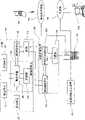
图3所示为根据本发明的门锁系统的视图,其中具有照相功能的功能扩展装置400与门锁420连接。FIG. 3 is a view of a door lock system according to the present invention, wherein a
在该门锁系统中,与图1所示的门锁100相似的门锁420包括控制器单元422、多用途接口装置控制单元424及多用途接口装置426。In the door lock system, a
另外,与图1所示的功能扩展装置200相似,具有照相功能的功能扩展装置400包括多用途接口装置连接单元402、多用途接口装置信号处理单元406和子模块404。并且,子模块404由照相模块410、I/O(输入/输出)端口412、存储器414和照相控制处理器408组成。为简单起见,这里将省略对已在图1中表示的有关的相同元件的详细说明。In addition, similar to the
按照上述结构,门锁420可以通过具有照相功能的功能扩展装置400给试图锁/解琐门锁420的人照相和/或摄像并存储所照像片。According to the above structure, the
照相控制处理器408是一种中心处理单元,它通过分析从多用途接口装置信号处理单元406传输的电信号来控制照相模块410、I/O端口412和存储器414。The
照相模块410包括CCD(电荷耦合器件)或CMOS(互补金属氧化物半导体)型图像拾取装置,并在照相控制处理器408的控制下给静止和/或移动物体照相。The
例如,I/O端口412包括销槽型连接器。功能扩展装置400通过I/O口端412与移动通讯终端(未示出)、计算机(未示出)和家庭网络服务器(未示出)连接。使用者通过使用移动通讯终端或计算机连接到家庭网络服务器并下载存储于存储器414中的静止照片和/或移动照片。For example, I/
存储器414包括EEPROM(电可擦可编程只读存储器)或闪存型存储装置,它们存储照相模块410产生的静止照片和移动照片。The
如果具有照相功能的功能扩展装置与上述门锁420连接,那么门锁420的功能以可以得到和存储试图锁/解锁的人的静止或移动的照片的方式被扩展。If a function expanding device having a camera function is connected to the above-mentioned
如果使用者带电子钥匙接近门锁420或输入密码以试图锁和解锁门锁420,识别单元(未示出)执行与电子钥匙或输入密码有关的识别过程。在进行识别过程中,识别单元产生并传输识别成功信号或识别失败信号至控制器单元422。If a user approaches the
接收到识别成功信号或识别失败信号的控制器单元422产生和传输一包括驱动成功信号或驱动失败信号的电信号至驱动单元(未示出)和多用途接口装置控制单元424。多用途接口装置控制单元424通过编码器对电信号进行编码,并通过门锁420的多用途接口装置426传输编码后的电信号至功能扩展装置400的多用途接口装置连接单元402。The
通过多用途接口装置连接单元402从门锁420传输的电信号被传输至功能扩展装置400的多用途接口装置信号处理单元406,并且多用途接口装置信号处理单元406对相应的电信号进行解码。解码后的电信号被传输至照相控制处理器408,并且照相控制处理器408根据接收的信号操作照相模块410。The electrical signal transmitted from the
操作照相模块410在照相控制处理器408的控制下给物体拍摄静止照片和/或移动照片。由操作照相模块410拍摄的静止照片和/或移动照片被传输至照相控制处理器408,照相控制处理器408将拍摄的静止照片和/或移动照片存储于存储器414。The operating
使用者可以通过连接移动通讯终端或计算机至外部I/O端口412来下载和确认存储于存储器414的静止照片和/或移动照片。Users can download and confirm still photos and/or moving photos stored in the
图4所示为在根据本发明的门锁系统中当功能扩展装置与门锁连接时的初始过程的流程图。FIG. 4 is a flowchart showing an initial process when a function expansion device is connected to a door lock in the door lock system according to the present invention.
功能扩展装置200连接至门锁100的多用途接口装置110(步骤S500)。门锁100的多用途接口装置控制单元112识别并判断连接至多用途接口装置110的功能扩展装置200是否为适当的装置,并校验多用途接口装置控制单元112提供的通讯协议是否与功能扩展装置200的通讯协议一致(步骤S502)。The
如果经判断功能扩展装置200是适当的装置并且多用途接口装置控制单元112的通讯协议与功能扩展装置200的通讯协议一致(步骤S502),控制器单元104使用通讯协议控制功能扩展装置200(步骤S504)。功能扩展装置200被控制的方式可以依靠功能扩展装置200的类型被改变。If it is judged that the
从以上描述显而易见的,按照本发明的易于改进的电子控制门锁系统,使当需要时,通过对使用中的门锁容易地和便宜地改进,从而增加新的如犯罪预防、指纹识别、火灾检测和与家庭网络交互的功能成为可能,意味着不用更换整个门锁就能改变或扩展门锁的功能。As apparent from the above description, the easily retrofittable electronically controlled door lock system according to the present invention makes it possible to add new functions such as crime prevention, fingerprint recognition, fire protection, etc. The ability to detect and interact with the home network means that the functionality of the lock can be changed or expanded without replacing the entire lock.
前述实施例仅仅为示范性的并且不应被解释为对本发明的限制。本教导可以被容易地应用于其它类型的装置。本发明的描述的目的是说明性的,不限制权利要求的范围。很多替换、修改和变化对本领域技术人员是显而易见的。The foregoing embodiments are exemplary only and should not be construed as limiting the present invention. The present teaching can be readily applied to other types of devices. The description of the present invention is presented for purposes of illustration and not to limit the scope of the claims. Many alternatives, modifications and variations will be apparent to those skilled in the art.
Claims (9)
Applications Claiming Priority (2)
| Application Number | Priority Date | Filing Date | Title |
|---|---|---|---|
| KR20040017568 | 2004-03-16 | ||
| KR1020040017568 | 2004-03-16 |
Publications (2)
| Publication Number | Publication Date |
|---|---|
| CN1934327A CN1934327A (en) | 2007-03-21 |
| CN100570115Ctrue CN100570115C (en) | 2009-12-16 |
Family
ID=35781961
Family Applications (1)
| Application Number | Title | Priority Date | Filing Date |
|---|---|---|---|
| CNB2005800083978AExpired - LifetimeCN100570115C (en) | 2004-03-16 | 2005-03-16 | Easy-to-modify electronically controlled door lock system |
Country Status (5)
| Country | Link |
|---|---|
| US (1) | US8035478B2 (en) |
| JP (1) | JP4545791B2 (en) |
| KR (1) | KR100664990B1 (en) |
| CN (1) | CN100570115C (en) |
| WO (1) | WO2006001572A1 (en) |
Families Citing this family (52)
| Publication number | Priority date | Publication date | Assignee | Title |
|---|---|---|---|---|
| DE60119351T2 (en) | 2000-09-26 | 2007-05-10 | The Procter & Gamble Company, Cincinnati | IMPROVED EMULSIFYING SYSTEMS FOR USE IN THE PRODUCTION OF DEHYDRATED STARCH INGREDIENTS |
| EP1991749A4 (en)* | 2006-02-24 | 2014-06-25 | Magt Pty Ltd | Door locking/unlocking unit |
| US20080092610A1 (en)* | 2006-10-20 | 2008-04-24 | Chung-Yi Kuo | Protective lock structure |
| US20090091422A1 (en)* | 2007-10-03 | 2009-04-09 | Apple Inc. | Device identification via serial communication link |
| AU2009201756B1 (en) | 2009-05-04 | 2010-05-20 | Nexkey, Inc. | Electronic locking system and method |
| CA2873271C (en)* | 2012-05-08 | 2018-01-02 | Schlage Lock Company Llc | Remote management of electronic products |
| US20130305353A1 (en)* | 2012-05-10 | 2013-11-14 | Rutherford Controls International Corp. | Low Power Driver System and Method for Controlling The Same |
| US9663972B2 (en) | 2012-05-10 | 2017-05-30 | Wesko Locks Ltd. | Method and system for operating an electronic lock |
| US10465422B2 (en) | 2012-05-10 | 2019-11-05 | 2603701 Ontario Inc. | Electronic lock mechanism |
| EP2974255A1 (en) | 2013-03-13 | 2016-01-20 | Spectrum Brands, Inc. | Electronic lock with remote monitoring |
| US10691953B2 (en) | 2013-03-15 | 2020-06-23 | August Home, Inc. | Door lock system with one or more virtual fences |
| US11802422B2 (en) | 2013-03-15 | 2023-10-31 | August Home, Inc. | Video recording triggered by a smart lock device |
| KR102038746B1 (en) | 2013-03-15 | 2019-10-30 | 스펙트럼 브랜즈, 인크. | Wireless lockset with integrated antenna, touch activation, and light communication device |
| US10443266B2 (en) | 2013-03-15 | 2019-10-15 | August Home, Inc. | Intelligent door lock system with manual operation and push notification |
| US10388094B2 (en)* | 2013-03-15 | 2019-08-20 | August Home Inc. | Intelligent door lock system with notification to user regarding battery status |
| US9916746B2 (en) | 2013-03-15 | 2018-03-13 | August Home, Inc. | Security system coupled to a door lock system |
| US9704314B2 (en) | 2014-08-13 | 2017-07-11 | August Home, Inc. | BLE/WiFi bridge that detects signal strength of Bluetooth LE devices at an exterior of a dwelling |
| KR101966846B1 (en)* | 2013-03-15 | 2019-04-08 | 사전트 매뉴팩츄어링 캄파니 | Configurable electrical connector key for electronic door locks |
| US10140828B2 (en) | 2015-06-04 | 2018-11-27 | August Home, Inc. | Intelligent door lock system with camera and motion detector |
| US11527121B2 (en) | 2013-03-15 | 2022-12-13 | August Home, Inc. | Door lock system with contact sensor |
| US11043055B2 (en) | 2013-03-15 | 2021-06-22 | August Home, Inc. | Door lock system with contact sensor |
| US11421445B2 (en) | 2013-03-15 | 2022-08-23 | August Home, Inc. | Smart lock device with near field communication |
| US10181232B2 (en) | 2013-03-15 | 2019-01-15 | August Home, Inc. | Wireless access control system and methods for intelligent door lock system |
| US11441332B2 (en) | 2013-03-15 | 2022-09-13 | August Home, Inc. | Mesh of cameras communicating with each other to follow a delivery agent within a dwelling |
| US11072945B2 (en) | 2013-03-15 | 2021-07-27 | August Home, Inc. | Video recording triggered by a smart lock device |
| US11352812B2 (en) | 2013-03-15 | 2022-06-07 | August Home, Inc. | Door lock system coupled to an image capture device |
| US9528296B1 (en) | 2013-03-15 | 2016-12-27 | August Home, Inc. | Off center drive mechanism for thumb turning lock system for intelligent door system |
| US9133647B2 (en) | 2013-10-11 | 2015-09-15 | Nexkey, Inc. | NFC or BLE based contactless lock with charge monitoring of its energy storage |
| CN104240350A (en)* | 2014-09-15 | 2014-12-24 | 陈忠泽 | Intelligent fingerprint key and fingerprint lock type access control system |
| KR101834337B1 (en)* | 2015-06-15 | 2018-03-05 | 김범수 | Electronic key and electronic locking apparatus of dual-authentication |
| EP3188136A1 (en) | 2015-12-28 | 2017-07-05 | Marques, SA | Electronic door lock and operation method thereof |
| WO2017165349A1 (en) | 2016-03-22 | 2017-09-28 | Spectrum Brands, Inc. | Garage door opener with touch sensor authentication |
| US10115257B2 (en)* | 2016-10-17 | 2018-10-30 | Roy T. Abner | Network connectivity module for electro-mechanical locks |
| ES2943290T3 (en) | 2016-10-19 | 2023-06-12 | Dormakaba Usa Inc | electromechanical lock core |
| US10943415B2 (en) | 2017-08-30 | 2021-03-09 | Sensormatic Electronics, LLC | System and method for providing communication over inductive power transfer to door |
| US10937262B2 (en)* | 2017-08-30 | 2021-03-02 | Sensormatic Electronics, LLC | Door system with power management system and method of operation thereof |
| US10968669B2 (en) | 2017-08-30 | 2021-04-06 | Sensormatic Electronics, LLC | System and method for inductive power transfer to door |
| WO2019051337A1 (en) | 2017-09-08 | 2019-03-14 | Dormakaba Usa Inc. | Electro-mechanical lock core |
| US11450158B2 (en) | 2018-01-05 | 2022-09-20 | Spectrum Brands, Inc. | Touch isolated electronic lock |
| US10968660B2 (en) | 2018-02-28 | 2021-04-06 | Passivebolt, Inc. | Electronic door lock |
| US11466473B2 (en) | 2018-04-13 | 2022-10-11 | Dormakaba Usa Inc | Electro-mechanical lock core |
| CN112752891B (en) | 2018-04-13 | 2022-08-05 | 多玛卡巴美国公司 | Electromechanical lock cylinder |
| US10657795B1 (en) | 2019-02-01 | 2020-05-19 | SimpliSafe, Inc. | Alarm system with first responder code for building access |
| US11639617B1 (en) | 2019-04-03 | 2023-05-02 | The Chamberlain Group Llc | Access control system and method |
| US11686126B2 (en) | 2019-07-18 | 2023-06-27 | Endura Products, Llc | Methods of operating a lock |
| US11933092B2 (en) | 2019-08-13 | 2024-03-19 | SimpliSafe, Inc. | Mounting assembly for door lock |
| US11002061B1 (en) | 2020-01-04 | 2021-05-11 | Passivebolt, Inc. | Electronic door system |
| CN116457545A (en) | 2020-09-17 | 2023-07-18 | 亚萨合莱股份有限公司 | Magnetic sensor for lock position |
| JP2023543572A (en) | 2020-09-25 | 2023-10-17 | アッサ・アブロイ・インコーポレイテッド | multidirectional door lock |
| JP2023543236A (en) | 2020-09-25 | 2023-10-13 | アッサ・アブロイ・インコーポレイテッド | door lock with magnetometer |
| US11821236B1 (en) | 2021-07-16 | 2023-11-21 | Apad Access, Inc. | Systems, methods, and devices for electronic dynamic lock assembly |
| CN114370202B (en)* | 2022-01-11 | 2022-09-09 | 中物合(河北)锁业有限公司 | Intelligent transformation device for building door lock and working method thereof |
Family Cites Families (23)
| Publication number | Priority date | Publication date | Assignee | Title |
|---|---|---|---|---|
| US3812403A (en)* | 1972-06-29 | 1974-05-21 | K Gartner | Electronic combination lock including sequential signal generator and signal display |
| US3777306A (en)* | 1972-10-16 | 1973-12-04 | Simpson A | Vehicle electronic security device |
| JPH0533536A (en) | 1991-07-26 | 1993-02-09 | Nippon Steel Corp | Key management storage |
| JPH06146674A (en) | 1992-11-10 | 1994-05-27 | Zexel Corp | Data input device of ic key lock system |
| US5848541A (en)* | 1994-03-30 | 1998-12-15 | Dallas Semiconductor Corporation | Electrical/mechanical access control systems |
| FR2729700B1 (en)* | 1995-01-25 | 1997-07-04 | Nofal Dawalibi | PROGRAMMABLE ELECTRONIC CLOSING DEVICE |
| US5818334A (en)* | 1995-02-03 | 1998-10-06 | Simplex Time Recorder Company | Addressable devices with interface modules having electrically readable addresses |
| US6038457A (en)* | 1997-12-05 | 2000-03-14 | Motorola, Inc. | Apparatus and method for detecting and powering an accessory |
| JP2000295360A (en)* | 1999-04-07 | 2000-10-20 | Shoji Hirabayashi | Post-installed cordless interphone unit |
| EP1175749B1 (en)* | 1999-04-22 | 2005-07-06 | Veridicom, Inc. | High security biometric authentication using a public key/private key encryption pairs |
| JP2001262913A (en)* | 2000-03-22 | 2001-09-26 | Komatsu Wall Ind Co Ltd | Sliding door closure device |
| CA2324679A1 (en)* | 2000-10-26 | 2002-04-26 | Lochisle Inc. | Method and system for physical access control using wireless connection to a network |
| AT4892U1 (en)* | 2000-11-03 | 2001-12-27 | Wolfram Peter | DEVICE FOR CONTROLLING FUNCTIONS VIA BIOMETRIC DATA |
| JP2003076436A (en) | 2001-08-31 | 2003-03-14 | Toyota Motor Corp | Portable electronic information equipment |
| JP2003129712A (en)* | 2001-10-26 | 2003-05-08 | Matsushita Electric Works Ltd | Common entrance locking-unlocking system |
| JP4094304B2 (en)* | 2002-02-12 | 2008-06-04 | 昌彦 清水 | Fingerprint authentication unlocking system |
| JP3808796B2 (en)* | 2002-04-17 | 2006-08-16 | 株式会社東海理化電機製作所 | Automatic door device |
| KR20020081168A (en)* | 2002-09-02 | 2002-10-26 | 김석균 | an electronic door lock |
| US20040123113A1 (en)* | 2002-12-18 | 2004-06-24 | Svein Mathiassen | Portable or embedded access and input devices and methods for giving access to access limited devices, apparatuses, appliances, systems or networks |
| KR100493883B1 (en)* | 2003-01-02 | 2005-06-10 | 삼성전자주식회사 | System and method for managing application |
| US7113070B2 (en)* | 2003-03-21 | 2006-09-26 | Sheng Bill Deng | Door lock and operation mechanism |
| KR200356844Y1 (en)* | 2004-04-22 | 2004-07-19 | 주식회사 아이레보 | Function Extension Battery-Pack of Door Lock and Door Lock having the same |
| KR200378844Y1 (en)* | 2004-12-10 | 2005-03-16 | 주식회사 아이레보 | Digital Door Lock Having Remote Control Pack of Detachable Type |
- 2005
- 2005-03-16CNCNB2005800083978Apatent/CN100570115C/ennot_activeExpired - Lifetime
- 2005-03-16USUS10/592,846patent/US8035478B2/enactiveActive
- 2005-03-16JPJP2007503832Apatent/JP4545791B2/ennot_activeExpired - Fee Related
- 2005-03-16WOPCT/KR2005/000756patent/WO2006001572A1/enactiveApplication Filing
- 2005-03-16KRKR1020050021827Apatent/KR100664990B1/ennot_activeCeased
Also Published As
| Publication number | Publication date |
|---|---|
| KR20060043699A (en) | 2006-05-15 |
| JP2007529658A (en) | 2007-10-25 |
| KR100664990B1 (en) | 2007-01-04 |
| US20070204663A1 (en) | 2007-09-06 |
| US8035478B2 (en) | 2011-10-11 |
| CN1934327A (en) | 2007-03-21 |
| WO2006001572A1 (en) | 2006-01-05 |
| JP4545791B2 (en) | 2010-09-15 |
Similar Documents
| Publication | Publication Date | Title |
|---|---|---|
| CN100570115C (en) | Easy-to-modify electronically controlled door lock system | |
| CN105009558B (en) | Electronic lock with remote monitoring | |
| CN204926231U (en) | Entrance guard and access control system | |
| TWI872222B (en) | Electronic lock pairing via passcode, and method and system for providing secure passcode-triggered wireless communication pairing of a mobile device with an electronic lock | |
| US11263844B2 (en) | Electronic lock, system, and take over lock module, and method of managing the same | |
| Vamsi et al. | Face recognition based door unlocking system using Raspberry Pi | |
| EP1977362A2 (en) | Safe with controllable data transfer capability | |
| TW201814121A (en) | Lock system, electronic lock, portable apparatus with certification function and pairing method | |
| CN112868215A (en) | System and method for establishing server connection with Internet of things equipment comprising electronic lock | |
| JP5074857B2 (en) | Electric lock system | |
| CN106761000A (en) | The external control system of intelligent door lock and method | |
| JP2017214702A (en) | Lock opening/closing management system | |
| TW201638445A (en) | Easy-to-retrofit, electronically controlled door lock system | |
| CN202711348U (en) | Door opened and closed under remote control | |
| CN205302437U (en) | Novel intelligent tool to lock | |
| KR102235991B1 (en) | Door handle, door handle control method, device and storage medium | |
| TW202007125A (en) | Communication device, communication system, method of information terminal and program for information terminal | |
| CN108830973A (en) | Intelligent door access control device and its control method | |
| CN109629930A (en) | Control equipment, door and the method for controlling unlocking authority of unlocking authority | |
| CN116092219A (en) | Over-the-air updates for IOT devices such as wireless electronic locks | |
| CN208502463U (en) | Intelligent lock based on battery box replacement control substrate | |
| TWM521661U (en) | Electronic lock system | |
| KR101866535B1 (en) | Smart phone docking door lock | |
| JP6796804B2 (en) | Electric lock system and electric lock device | |
| JP7745213B2 (en) | Apartment complex intercom system and residential intercom system |
Legal Events
| Date | Code | Title | Description |
|---|---|---|---|
| C06 | Publication | ||
| PB01 | Publication | ||
| C10 | Entry into substantive examination | ||
| SE01 | Entry into force of request for substantive examination | ||
| C14 | Grant of patent or utility model | ||
| GR01 | Patent grant | ||
| TR01 | Transfer of patent right | Effective date of registration:20180703 Address after:Seoul, South Kerean Patentee after:ASSA ABLOY Korea Address before:Seoul, South Kerean Patentee before:IREVO, Inc. | |
| TR01 | Transfer of patent right | ||
| CX01 | Expiry of patent term | Granted publication date:20091216 | |
| CX01 | Expiry of patent term |