CN100569193C - Tool and method for continuous delivery of orthopaedic paste - Google Patents
Tool and method for continuous delivery of orthopaedic pasteDownload PDFInfo
- Publication number
- CN100569193C CN100569193CCNB2006800214593ACN200680021459ACN100569193CCN 100569193 CCN100569193 CCN 100569193CCN B2006800214593 ACNB2006800214593 ACN B2006800214593ACN 200680021459 ACN200680021459 ACN 200680021459ACN 100569193 CCN100569193 CCN 100569193C
- Authority
- CN
- China
- Prior art keywords
- glue
- chamber
- tube
- orthopedic
- bone
- Prior art date
- Legal status (The legal status is an assumption and is not a legal conclusion. Google has not performed a legal analysis and makes no representation as to the accuracy of the status listed.)
- Expired - Fee Related
Links
Images


Classifications
- G—PHYSICS
- G01—MEASURING; TESTING
- G01F—MEASURING VOLUME, VOLUME FLOW, MASS FLOW OR LIQUID LEVEL; METERING BY VOLUME
- G01F11/00—Apparatus requiring external operation adapted at each repeated and identical operation to measure and separate a predetermined volume of fluid or fluent solid material from a supply or container, without regard to weight, and to deliver it
- G01F11/02—Apparatus requiring external operation adapted at each repeated and identical operation to measure and separate a predetermined volume of fluid or fluent solid material from a supply or container, without regard to weight, and to deliver it with measuring chambers which expand or contract during measurement
- G01F11/021—Apparatus requiring external operation adapted at each repeated and identical operation to measure and separate a predetermined volume of fluid or fluent solid material from a supply or container, without regard to weight, and to deliver it with measuring chambers which expand or contract during measurement of the piston type
- G01F11/025—Apparatus requiring external operation adapted at each repeated and identical operation to measure and separate a predetermined volume of fluid or fluent solid material from a supply or container, without regard to weight, and to deliver it with measuring chambers which expand or contract during measurement of the piston type with manually operated pistons
- G01F11/026—Apparatus requiring external operation adapted at each repeated and identical operation to measure and separate a predetermined volume of fluid or fluent solid material from a supply or container, without regard to weight, and to deliver it with measuring chambers which expand or contract during measurement of the piston type with manually operated pistons of the gun type
- A—HUMAN NECESSITIES
- A61—MEDICAL OR VETERINARY SCIENCE; HYGIENE
- A61B—DIAGNOSIS; SURGERY; IDENTIFICATION
- A61B17/00—Surgical instruments, devices or methods
- A61B17/56—Surgical instruments or methods for treatment of bones or joints; Devices specially adapted therefor
- A61B17/58—Surgical instruments or methods for treatment of bones or joints; Devices specially adapted therefor for osteosynthesis, e.g. bone plates, screws or setting implements
- A61B17/88—Osteosynthesis instruments; Methods or means for implanting or extracting internal or external fixation devices
- A61B17/8802—Equipment for handling bone cement or other fluid fillers
- A61B17/8805—Equipment for handling bone cement or other fluid fillers for introducing fluid filler into bone or extracting it
- A61B17/8822—Equipment for handling bone cement or other fluid fillers for introducing fluid filler into bone or extracting it characterised by means facilitating expulsion of fluid from the introducer, e.g. a screw pump plunger, hydraulic force transmissions, application of vibrations or a vacuum
- A—HUMAN NECESSITIES
- A61—MEDICAL OR VETERINARY SCIENCE; HYGIENE
- A61B—DIAGNOSIS; SURGERY; IDENTIFICATION
- A61B17/00—Surgical instruments, devices or methods
- A61B17/56—Surgical instruments or methods for treatment of bones or joints; Devices specially adapted therefor
- A61B17/58—Surgical instruments or methods for treatment of bones or joints; Devices specially adapted therefor for osteosynthesis, e.g. bone plates, screws or setting implements
- A61B17/88—Osteosynthesis instruments; Methods or means for implanting or extracting internal or external fixation devices
- A61B17/8802—Equipment for handling bone cement or other fluid fillers
- A61B17/8833—Osteosynthesis tools specially adapted for handling bone cement or fluid fillers; Means for supplying bone cement or fluid fillers to introducing tools, e.g. cartridge handling means
- A—HUMAN NECESSITIES
- A61—MEDICAL OR VETERINARY SCIENCE; HYGIENE
- A61F—FILTERS IMPLANTABLE INTO BLOOD VESSELS; PROSTHESES; DEVICES PROVIDING PATENCY TO, OR PREVENTING COLLAPSING OF, TUBULAR STRUCTURES OF THE BODY, e.g. STENTS; ORTHOPAEDIC, NURSING OR CONTRACEPTIVE DEVICES; FOMENTATION; TREATMENT OR PROTECTION OF EYES OR EARS; BANDAGES, DRESSINGS OR ABSORBENT PADS; FIRST-AID KITS
- A61F2/00—Filters implantable into blood vessels; Prostheses, i.e. artificial substitutes or replacements for parts of the body; Appliances for connecting them with the body; Devices providing patency to, or preventing collapsing of, tubular structures of the body, e.g. stents
- A61F2/02—Prostheses implantable into the body
- A61F2/30—Joints
- A61F2/46—Special tools for implanting artificial joints
- A61F2/4601—Special tools for implanting artificial joints for introducing bone substitute, for implanting bone graft implants or for compacting them in the bone cavity
- G—PHYSICS
- G01—MEASURING; TESTING
- G01F—MEASURING VOLUME, VOLUME FLOW, MASS FLOW OR LIQUID LEVEL; METERING BY VOLUME
- G01F11/00—Apparatus requiring external operation adapted at each repeated and identical operation to measure and separate a predetermined volume of fluid or fluent solid material from a supply or container, without regard to weight, and to deliver it
- G01F11/02—Apparatus requiring external operation adapted at each repeated and identical operation to measure and separate a predetermined volume of fluid or fluent solid material from a supply or container, without regard to weight, and to deliver it with measuring chambers which expand or contract during measurement
- G01F11/021—Apparatus requiring external operation adapted at each repeated and identical operation to measure and separate a predetermined volume of fluid or fluent solid material from a supply or container, without regard to weight, and to deliver it with measuring chambers which expand or contract during measurement of the piston type
- G01F11/029—Apparatus requiring external operation adapted at each repeated and identical operation to measure and separate a predetermined volume of fluid or fluent solid material from a supply or container, without regard to weight, and to deliver it with measuring chambers which expand or contract during measurement of the piston type provided with electric controlling means
- A—HUMAN NECESSITIES
- A61—MEDICAL OR VETERINARY SCIENCE; HYGIENE
- A61F—FILTERS IMPLANTABLE INTO BLOOD VESSELS; PROSTHESES; DEVICES PROVIDING PATENCY TO, OR PREVENTING COLLAPSING OF, TUBULAR STRUCTURES OF THE BODY, e.g. STENTS; ORTHOPAEDIC, NURSING OR CONTRACEPTIVE DEVICES; FOMENTATION; TREATMENT OR PROTECTION OF EYES OR EARS; BANDAGES, DRESSINGS OR ABSORBENT PADS; FIRST-AID KITS
- A61F2/00—Filters implantable into blood vessels; Prostheses, i.e. artificial substitutes or replacements for parts of the body; Appliances for connecting them with the body; Devices providing patency to, or preventing collapsing of, tubular structures of the body, e.g. stents
- A61F2/02—Prostheses implantable into the body
- A61F2/30—Joints
- A61F2002/30001—Additional features of subject-matter classified in A61F2/28, A61F2/30 and subgroups thereof
- A61F2002/30316—The prosthesis having different structural features at different locations within the same prosthesis; Connections between prosthetic parts; Special structural features of bone or joint prostheses not otherwise provided for
- A61F2002/30535—Special structural features of bone or joint prostheses not otherwise provided for
- A61F2002/30601—Special structural features of bone or joint prostheses not otherwise provided for telescopic
Landscapes
- Health & Medical Sciences (AREA)
- Orthopedic Medicine & Surgery (AREA)
- Life Sciences & Earth Sciences (AREA)
- Surgery (AREA)
- Heart & Thoracic Surgery (AREA)
- Veterinary Medicine (AREA)
- Public Health (AREA)
- General Health & Medical Sciences (AREA)
- Animal Behavior & Ethology (AREA)
- Engineering & Computer Science (AREA)
- Biomedical Technology (AREA)
- Nuclear Medicine, Radiotherapy & Molecular Imaging (AREA)
- Physics & Mathematics (AREA)
- Molecular Biology (AREA)
- Medical Informatics (AREA)
- Transplantation (AREA)
- Fluid Mechanics (AREA)
- General Physics & Mathematics (AREA)
- Vascular Medicine (AREA)
- Physical Education & Sports Medicine (AREA)
- Cardiology (AREA)
- Oral & Maxillofacial Surgery (AREA)
- Prostheses (AREA)
- Surgical Instruments (AREA)
- Materials For Medical Uses (AREA)
Abstract
Description
Translated fromChinese技术领域technical field
本发明涉及一种将矫形胶输送到骨内的技术,这种胶将在骨内硬化并作为医疗植入物。矫形胶可以是现有任何易流动的矫形填充材料,例如,包括液体-粉末混合物和包含聚合物材料的粘性液体。The present invention relates to a technique for delivering orthopedic glue into bone where it will harden and serve as a medical implant. The orthopedic gel can be any flowable orthopedic filler material available, including, for example, liquid-powder mixtures and viscous liquids comprising polymeric materials.
背景技术Background technique
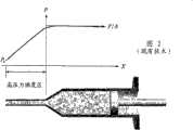
图1是将矫形胶从容器经过细管输送到指定点(骨腔)的普通方法的示意图。一般是将贮存在容器或贮存器内的液体-固体两相混合物矫形胶,通过细管输送到病体的骨结构、细胞或组织中的指定点。常用的是一种连接容器和细管(注射器)的带梢锥形-柱体结构,这时要施加驱动力来输送矫形胶。对于这种一步式直接强制填充法,矫形胶的液体和粉末在填充过程中受到力的作用后将易于分离。下面将解析其物理本质。Figure 1 is a schematic diagram of a common method of delivering orthopedic gel from a container through a thin tube to a designated point (bone cavity). Generally, the liquid-solid two-phase mixture orthopedic glue stored in a container or reservoir is delivered to a designated point in the bone structure, cells or tissues of the disease body through a thin tube. Commonly used is a tipped cone-cylinder structure that connects a container and a thin tube (syringe), where a driving force is applied to deliver the orthopedic gel. For this one-step direct force filling method, the liquid and powder of the orthopedic gel will be easy to separate after being subjected to force during the filling process. Its physical nature will be analyzed below.
一般来说,图1所示方法的输送速度缓慢。在整个填充过程中容器内发生的物理现象可用静平衡概念来说明。所产生的内压力约等于所施加的力除以支承板的面积,即F/A。此压力(P)几乎均匀地分布在各处,除了容器出口区附近区域,即靠近细管的区域,在此区域压力骤降至指定点的环境压力(P0),如图2所示。在容器和细管连接处产生的局部压力梯度,形成将矫形胶混合物的流体部分推出容器小漏斗的主要机制。这可以用流体流动的不可压缩Navier-Stokes运动方程来说明,In general, the delivery rate of the method shown in Figure 1 is slow. The physical phenomena that occur in the container during the entire filling process can be described by the concept of static equilibrium. The resulting internal pressure is approximately equal to the applied force divided by the area of the support plate, F/A. This pressure (P) is distributed almost uniformly everywhere except in the region near the exit region of the vessel, i.e. near the capillary, where the pressure drops sharply to the ambient pressure (P0 ) at a given point, as shown in Figure 2. The local pressure gradient created at the junction of the container and tubule forms the primary mechanism for pushing the fluid portion of the orthopedic gel mixture out of the small funnel of the container. This can be stated in terms of the incompressible Navier-Stokes equations of motion for fluid flow,
式中ρ、u、v、p和μ分别为流体的密度、速度分量、压力和粘度,(x,y,t)为笛卡儿和时间坐标。由于矫形胶输送运动一般很慢,所以不稳定项和对流项可以忽略,结果使压力梯度和粘度项达到平衡。换句话说,局部产生的压力梯度通过克服流体射出时的内部或管壁摩擦而使流体运动。由于固-液密度比较大,流体的速度通常超过固体颗粒的速度,这会造成矫形胶的组成物分离。由于流体运动的连续性,矫形胶的流体部分将从容器连续流出。但是,当施加力时,矫形胶的固体部分将经受不同的物理机制。在一开始,由于被压出容器的液体多于固体部分,因此将注入较稀的矫形胶。剩下的矫形胶在加压期间将变得更干燥。小的出口面积妨碍干燥的固体颗粒从容器中很快地移出。除了随液体载体漂出容器的初始粉末之外,矫形胶中剩下的粉末将紧密地堆积或连结在一起,结果由于流动性下降而产生静平衡块。这种液体-固体分离机制说明了为什么一步式直接强迫填充装置往往不是一种令人满意的矫形胶输送注入器,尤其是对于侵入量极小的手术过程。where ρ, u, v, p and μ are the density, velocity component, pressure and viscosity of the fluid, respectively, and (x, y, t) are Cartesian and time coordinates. Since the delivery motion of orthopedic gel is generally very slow, the instability and convection terms can be ignored, resulting in a balance between the pressure gradient and viscosity terms. In other words, the locally created pressure gradient sets the fluid in motion by overcoming internal or tube wall friction as it is ejected. Due to the solid-liquid density ratio, the velocity of the fluid usually exceeds the velocity of the solid particles, which can cause the components of the orthopedic gel to separate. Due to the continuity of fluid motion, the fluid portion of the orthopedic gel will continuously flow from the container. However, the solid portion of the orthopedic gel will experience a different physical mechanism when force is applied. In the beginning, a thinner orthopedic gel will be injected since more liquid than solids will be pressed out of the container. The rest of the orthopedic gel will become drier during pressurization. The small outlet area prevents the dry solids from being removed quickly from the container. In addition to the initial powder that floats out of the container with the liquid carrier, the remaining powder in the orthopedic gel will be tightly packed or bonded together, resulting in a static mass due to decreased flow. This liquid-solid separation mechanism illustrates why a one-step direct force-fill device is often not a satisfactory injector for orthopedic adhesive delivery, especially for minimally invasive surgical procedures.
美国专利申请No.2005/0113843A1公开了一种用于输送粘性流体的注入系统。典型的流体包括诸如聚甲基丙烯酸甲酯(PMMA)等易流动的硬细胞植入材料等。此植入材料注入系统包括压力驱动器,和用于植入材料的分离容器,其中所述驱动器和所述分离容器适用于在相互间形成压力密封界面,所述压力驱动器包括活塞和套筒,其中所述活塞和套筒适用于将植入材料吸入室(当活塞缩回时由套筒界定)的至少一部分内,同时在活塞前推时将植入材料从处于某压力水平的所述压力驱动器挤出。虽然此种结构可用于输送低粘性流体或胶;然而,这种结构在输送如CPC等高粘性骨水泥时至少具有下述缺点:US Patent Application No. 2005/0113843A1 discloses an injection system for delivering viscous fluids. Typical fluids include flowable rigid cell implant materials such as polymethyl methacrylate (PMMA), and the like. The implant material injection system includes a pressure driver, and a separate container for the implant material, wherein the driver and the separate container are adapted to form a pressure-tight interface therebetween, the pressure driver includes a piston and a sleeve, wherein The piston and sleeve are adapted to draw implant material into at least a portion of a chamber (bounded by the sleeve when the piston is retracted) while simultaneously drawing implant material from said pressure drive at a pressure level as the piston is advanced. extrude. Although this structure can be used to deliver low-viscosity fluids or glue; however, this structure has at least the following disadvantages when delivering high-viscosity bone cements such as CPC:
(a)贮存器内的胶上没有直接压力,这可能会在将高粘性胶顺利移入“备用”位置(由此结构中的“套筒”所确定的空间)时造成困难。(a) There is no direct pressure on the glue in the reservoir, which may cause difficulties in smoothly moving the high-viscosity glue into the "standby" position (the space defined by the "sleeve" in this structure).
(b)使用套筒可能有助于套筒内压力的增高,以便更容易地将低粘性胶驱入注入管内。然而,这种由套筒引发的压力增长在输送高粘性粘骨水泥时可能会引起不希望有的固体-液体分离。另外,套筒的存在将使操作更困难。(b) The use of a sleeve may facilitate increased pressure within the sleeve to more easily drive the low-viscosity glue into the injection tube. However, this pressure increase induced by the sleeve may cause undesirable solid-liquid separation when delivering highly viscous bone cement. In addition, the presence of the sleeve will make handling more difficult.
(c)套筒和注入管之间的直径的显著差别也会引起CPC的固体-液体分离。(c) A significant difference in diameter between the sleeve and the injection tube can also cause solid-liquid separation of the CPC.
美国专利申请No.2004/0174768A1公开了一种骨水泥混合物和输送装置,用来混合粉末状光聚物和液体单聚物以形成骨水泥并输送该骨水泥。此装置包括筒体,所述筒体具有远端和近端以及在远端、近端之间界定混合室。传递机构具有盖和支撑活塞与柱塞的杆并与所述远端相连接。所述传递机构包括用来同时推进活塞和柱塞的第一推进机构,和使柱塞独立于活塞运动的第二推进机构。此组件还包括可动把手,该可动把手具有用来安装混合叶片的轴和用来将所述混合叶片与可动把手锁住和打开的快速释放连接器及释放按钮。此结构可将要转移的骨水泥全部转移(注入)而不剩余的优点。但是由于上面所述的原因,当使用这种装置时,在第一次推进过程中将会发生CPC骨水泥的固体-液体分离。US Patent Application No. 2004/0174768A1 discloses a bone cement mixture and delivery device for mixing powdered photopolymer and liquid monomer to form bone cement and delivering the bone cement. The device includes a barrel having a distal end and a proximal end and defining a mixing chamber therebetween. A transfer mechanism has a cap and a rod supporting the piston and plunger and is connected to the distal end. The transfer mechanism includes a first advancement mechanism for simultaneously advancing the piston and plunger, and a second advancement mechanism for moving the plunger independently of the piston. This assembly also includes a movable handle having a shaft for mounting the mixing blade and a quick release connector and release button for locking and unlocking the mixing blade from the movable handle. This structure has the advantage that all the bone cement to be transferred can be transferred (injected) without remaining. However, when using this device, solid-liquid separation of the CPC bone cement will occur during the first push for the reasons stated above.
美国专利No.6,033,105公开了一种整体式全集成骨水泥混合和配送系统,它具有唯一的壳体,包含与输送室或管整体组合的混合室,故用户不用接触或搬运已混合的骨水泥。在该现有技术中,集成系统的两个室可以在两个交替位置之间运动,处于第一位置时各室之间彼此密封,而在第二位置时所述两个室是彼此直接连通的。这样,混合室就独立于置备骨水泥的室工作,一旦置备好骨水泥,就可方便地通过输送室从混合室传送出去。提供了一种双驱动装置,该装置可独立地按第一速度和方向旋转混合叶片,并以第二速度和方向独立控制送料控制元件的速度和旋转。因而容易把混合部分的速率或转速,相对于输送室内控制部分旋转运动的速度,控制到任意希望的水平。在这种现有技术的设计中,若不在混合室内的CPC骨水泥上直接施加直接压力,则不能将高黏稠性CPC骨水泥“拉”入注入管内。当加上压力时,小开口(直径突变)触发CPC骨水泥的固体-液体分离。U.S. Patent No. 6,033,105 discloses a one-piece fully integrated bone cement mixing and dispensing system having a unique housing containing the mixing chamber integrally combined with the delivery chamber or tube so the user does not have to touch or handle the mixed bone cement . In this prior art, the two chambers of the integrated system can be moved between two alternate positions, a first position in which the chambers are sealed from each other, and a second position in which the two chambers are in direct communication with each other of. In this way, the mixing chamber works independently of the chamber where the cement is prepared, and once the cement is prepared, it can be conveniently transferred from the mixing chamber through the delivery chamber. A dual drive arrangement is provided which independently rotates the mixing blade at a first speed and direction and independently controls the speed and rotation of the feed control element at a second speed and direction. It is thus easy to control the speed or rotational speed of the mixing section to any desired level relative to the speed of the rotational movement of the control section within the delivery chamber. In this prior art design, the highly viscous CPC cement cannot be "pulled" into the injection tube without applying direct pressure on the CPC cement within the mixing chamber. When pressure is applied, small openings (diameter abrupt changes) trigger solid-liquid separation of the CPC bone cement.
发明内容Contents of the invention
本发明的主要目的是提供一种用于将贮存在室内的矫形胶通过管子连续输送到骨头中的工具和方法。The main object of the present invention is to provide a tool and method for continuously delivering orthopedic glue stored in a chamber into a bone through a tube.
本发明的另一目的是提供一种工具和方法,用于在输送过程中室内压力不增高的情况下,将贮存在室内的矫形胶通过管子连续输送到骨头中。Another object of the present invention is to provide a tool and method for continuously delivering the orthopedic glue stored in the chamber to the bone through the tube without increasing the pressure in the chamber during the delivery.
本发明的再一个目的是提供一种工具和方法,用于将包含颗粒和液体的矫形胶通过管子输送到骨头中,而不显著改变流经管子的胶的固体/液体比。Yet another object of the present invention is to provide a means and method for delivering orthopedic glue comprising particles and liquid through a tube into bone without significantly changing the solids/liquid ratio of the glue flowing through the tube.
为实现本发明的上述目的,采用一种替代机构,通过与室流体连通的管子来输送贮存在该室内的胶,所述机构包括用小体积的补偿元件诸如杆将胶侵入室内来代替使相同体积的胶进入管内,并在对室内的胶施加压力的同时缩回该侵入杆,使得由缩回所造成的空间被胶替代,并交替重复该侵入和缩回过程。To achieve the above objects of the present invention, an alternative mechanism is used to deliver the glue stored in the chamber through a tube in fluid communication with the chamber, said mechanism comprising invading the glue into the chamber with a compensating element of small volume, such as a rod, instead of allowing the same A volume of glue enters the tube and retracts the intrusion rod while exerting pressure on the glue in the chamber so that the space created by the retraction is replaced by glue, and the process of intrusion and retraction is repeated alternately.
本发明的还有一个目的是提供用来混合颗粒和液体以形成矫形胶的混合器。所述混合器优选包含贮存室,所述室具有与该室的一端以可拆卸方式相连的盖;叶轮;杯体;活塞,其中所述室以可拆卸且充分密封的方式与所述杯体相连接,以在室和杯体内形成封闭空间;叶轮安装在杯体内以使该叶轮能在此封闭空间内搅拌混合物;活塞可滑动地装在室内,且当该活塞处于室内中间位置时将此封闭空间分成一上空间和一下空间;叶轮处在所述下空间内;该室还具有用来接纳正压源的出口和与上空间相连通的入口,以及将入口与出口连接的通道。叶轮最好包含轴和至少一个叶片,其中该轴可旋转地安装在杯体的孔内,轴的一端通过电机驱动,轴的另一端与位于下空间内的所述至少一个叶片连接。活塞最好具有可关闭的空气通气口以将下空间与上空间连通。此可关闭的空气通气口可以是插在活塞的通孔内的针状密封短管。Yet another object of the present invention is to provide a mixer for mixing granules and liquid to form orthopedic gels. The mixer preferably comprises a reservoir chamber having a cover removably connected to one end of the chamber; an impeller; a cup; a piston wherein the chamber is removably and substantially sealed to the cup Connected to form a closed space in the chamber and the cup; the impeller is installed in the cup so that the impeller can stir the mixture in the closed space; the piston is slidably installed in the chamber, and when the piston is in the middle of the chamber The enclosed space is divided into an upper space and a lower space; the impeller is located in the lower space; the chamber also has an outlet for receiving a positive pressure source, an inlet communicating with the upper space, and a passage connecting the inlet with the outlet. The impeller preferably includes a shaft and at least one blade, wherein the shaft is rotatably installed in the hole of the cup, one end of the shaft is driven by a motor, and the other end of the shaft is connected to the at least one blade located in the lower space. The piston preferably has a closable air vent to communicate the lower space with the upper space. The closable air vent can be a needle-shaped sealing stub inserted into the through hole of the piston.
本发明再一个目的是提供一种带孔囊形物,用以收集骨腔内的矫形胶,直至胶在骨腔内硬化,其中该带孔囊形物被安装在矫形胶输送工具的管子的一端,胶通过该管被注入囊形物内。所述带孔囊形物最好包括第一类开孔,且该第一类孔包含图形孔阵列,所述阵列在囊形物膨胀并受到外力时引起囊形物破裂,例如当推动已硬化的矫形胶管,或在矫形胶在囊形物内硬化后托住管子时推动已硬化矫形胶,而使管受拉或扭转时就可能产生这种外力。所述囊形物更优选包含第二类孔,例如微孔,以使囊形物中的矫形胶内所包含的液体能在压力下从囊形物排出。Another object of the present invention is to provide a porous capsule for collecting orthopedic glue in the bone cavity until the glue hardens in the bone cavity, wherein the porous capsule is installed in the tube of the orthopedic glue delivery tool At one end, glue is injected into the bladder through the tube. The perforated bladder preferably comprises a first type of opening comprising a patterned array of holes which causes the bladder to rupture when the bladder is inflated and subjected to an external force, such as when the push has hardened. Such external force may be generated when the tube is stretched or twisted by pushing the hardened orthopedic gel while holding the tube after it has hardened in the capsule. The bladder more preferably comprises a second type of pores, eg micropores, to enable fluid contained within the orthopedic gel in the bladder to escape from the bladder under pressure.
本发明再一个目的是提供一种不充气工具使将要植入矫形胶的骨腔膨胀。此膨胀工具优选包含柔软的线状填充物例如丝、带和链条和杆,所述杆的一端连至柔软的线状填充物的一端,其中可用杆将柔软的线状填充物推过管子进入骨头的孔内,以使骨头中的骨腔膨胀。丝和带沿其纵向可具有均匀的截面形状,或者也可以具有交替的重复大扇形和小扇形。链子可以是现有技术中的任何柔性链,且优选是一个接一个地或用线连接的珠子系列构成的链子。Yet another object of the present invention is to provide a non-inflatable tool for expanding a bone cavity into which orthopedic gel will be implanted. This expansion tool preferably consists of a flexible string of filler such as wire, ribbon and chain and a rod, one end of which is attached to one end of the flexible string of filler, wherein the rod can be used to push the flexible string of filler through the tube into the Inside the hole in the bone to expand the bony cavity in the bone. The filaments and ribbons can have a uniform cross-sectional shape along their longitudinal direction, or alternatively can have alternating repeating large and small fans. The chain may be any flexible chain known in the art, and is preferably a chain of series of beads connected one after the other or with a thread.
本发明的另一个目的是提供一种手术管(导管、注入管等),该手术管的前端具有防止血/体液进入手术管的装置,且通过施力例如通过注入矫形胶所产生的力就很容易打开或弄破该装置。该装置优选是上面带或不带凹痕,压痕,凹槽等图案的薄膜,并具有足够的强度以抵御病人的血/体液施加在上面的压力,同时又充分脆弱,通过注入矫形胶就很容易弄破。这种装置也可以是单向盖或阀门。Another object of the present invention is to provide a surgical tube (catheter, injection tube, etc.) that has a device at the front end that prevents blood/body fluid from entering the surgical tube, and that is It is easy to open or break the device. The device is preferably a thin film with or without a pattern of indentations, indentations, grooves, etc., and is strong enough to resist the pressure exerted on it by the patient's blood/body fluids, yet sufficiently fragile to be fixed by injecting orthopedic glue. It is easy to break. This device may also be a one-way cap or valve.
附图说明Description of drawings
图1是现有技术中的一步式直接强制填充矫形胶工具的局部剖视图。Fig. 1 is a partial sectional view of a one-step direct forced filling orthopedic glue tool in the prior art.
图2是图1所示的现有技术中的一步式直接强制填充矫形胶工具在胶推进方向(X)上的压力分布图。Fig. 2 is a pressure distribution diagram of the one-step direct forced filling orthopedic glue tool in the prior art shown in Fig. 1 in the glue advancing direction (X).
图3是本发明的水平式两步骤矫形胶送料装置的局部剖视图。Fig. 3 is a partial sectional view of the horizontal two-step orthopedic glue feeding device of the present invention.
图4是本发明的立式两步骤矫形胶送料装置的局部剖视图。Fig. 4 is a partial sectional view of the vertical two-step orthopedic glue feeding device of the present invention.
图5是本发明的立式两步骤矫形胶送料工具的剖视图。Figure 5 is a cross-sectional view of the vertical two-step orthopedic glue delivery tool of the present invention.
图6是用在图5所示工具的矫形胶注入控制环示意图。FIG. 6 is a schematic diagram of the orthopedic glue injection control ring used in the tool shown in FIG. 5 .
图7是本发明所述矫形胶混合器的局部剖视图。Fig. 7 is a partial sectional view of the orthopedic glue mixer of the present invention.
图8是本发明所述的带孔囊形物的正视图,所述囊形物用于收集骨腔内的矫形胶,直至胶在骨腔内硬化。Fig. 8 is a front view of a porous capsule according to the present invention, which is used to collect orthopedic glue in the bone cavity until the glue hardens in the bone cavity.
图9是图8所示带孔囊形物的侧视图。Figure 9 is a side view of the perforated bladder shown in Figure 8 .
图10是本发明所述手术管的正视图,所述手术管的前端具有用以防止血/体液进入手术管内的装置,。Fig. 10 is a front view of the surgical tube of the present invention, the front end of the surgical tube has a device for preventing blood/body fluid from entering the surgical tube.
图11是图10所述手术管的剖视图。FIG. 11 is a cross-sectional view of the surgical tube of FIG. 10 .
图12是本发明所述的用来使骨腔膨胀的填充物的侧视图。Figure 12 is a side view of a filler for expanding a bone cavity according to the present invention.
图13是本发明所述的用来使骨腔膨胀的另一种填充物的侧视图。图14至17是利用本发明的填充物使骨腔膨胀的操作过程各阶段的侧视图。Figure 13 is a side view of another filler used to expand a bone cavity according to the present invention. Figures 14 to 17 are side views of various stages in the procedure for expanding a bone cavity using the filler of the present invention.
具体实施方式Detailed ways
本发明包括(但不局限于)以下各优选实施例:The present invention includes (but not limited to) the following preferred embodiments:
1.一种矫形胶输送工具,包括:1. A delivery tool for orthopedic glue, comprising:
用于贮存矫形胶的室;chambers for storing orthopedic glue;
与贮存在所述室内的胶流体连通的管子;a tube in fluid communication with glue stored within the chamber;
活动安装在设置于室壁上的孔内的补偿元件,该元件可以从第一位置被推移至第二位置,使得该补偿元件的一部分侵入贮存在室内的胶中,并因而使胶进入管内,胶的量基本相当于该补偿元件侵入部分的体积;及a compensating element movably mounted in a hole provided in the chamber wall, which element can be moved from a first position to a second position, so that a part of the compensating element penetrates into the glue stored in the chamber and thus allows the glue to enter the tube, an amount of glue substantially corresponding to the volume of the intrusion of the compensating element; and
与贮存在室内的胶相接触的压紧元件,该元件将贮存在室内的胶压紧,以消除当补偿元件从第二位置被拉向第一位置时在室内所产生的空间。A compression element in contact with the glue stored in the chamber compresses the glue stored in the chamber to eliminate the space created in the chamber when the compensating element is pulled from the second position to the first position.
2.如条目1所述的工具,其中所述补偿元件有一个杆,它的直径不到管内径的20倍。2. The tool according to item 1, wherein the compensating element has a rod whose diameter is less than 20 times the inner diameter of the tube.
3.如条目2所述的工具,其中所述杆的直径范围从管内径的5倍至小于管内径。3. The tool of
4.如条目1所述的工具,其中该压紧元件是滑动安装在室内的板,且板的一面与贮存在室内的胶相接触,另一面用来接纳正压力源。4. The tool according to item 1, wherein the pressing element is a plate slidably mounted in the chamber, with one side of the plate in contact with the glue stored in the chamber and the other side adapted to receive a positive pressure source.
5.如条目4所述的工具,其中板和/或正压力源的重量有助于上述压紧作用。5. The tool according to item 4, wherein the weight of the plate and/or the positive pressure source contributes to the above-mentioned compaction.
6.如条目5所述的工具,其中板、正压力源或它们的组合的重量,不足以使贮存在室内的大量胶进入管子。6. The tool of clause 5, wherein the weight of the plate, the source of positive pressure, or a combination thereof is insufficient to allow a substantial amount of glue stored in the chamber to enter the tube.
7.如条目4所述的工具,还包括一个驱动装置,用来往复地进行补偿元件的推和拉。7. The tool according to item 4, further comprising a drive means for reciprocatingly pushing and pulling the compensating element.
8.如条目7所述的工具,其中所述驱动装置包括气动缸。8. The tool according to
9.一种输送矫形胶的方法,包括以下步骤:9. A method of delivering orthopedic gel, comprising the following steps:
用胶填充室,胶与管子流体连通;filling the chamber with glue, the glue being in fluid communication with the tube;
用压力压紧室内的胶,此压力不足以使室内的大量胶进入管内;Use pressure to compress the glue in the chamber, which is not enough to make a large amount of glue in the chamber enter the pipe;
往复地推动补偿元件以将胶侵入室内,并拉动侵入室内的补偿元件,使得进入管子的胶量基本相当于由于所述推动而侵入的补偿元件部分的体积,同时由于所述拉动而在室内产生的空间因压紧而消失,所以室内的胶可通过该管进行连续输送。reciprocatingly pushing the compensating element to invade the glue into the chamber, and pulling the compensating element intruding into the chamber, so that the amount of glue entering the tube is substantially equivalent to the volume of the part of the compensating element invaded due to said pushing, while simultaneously creating The space in the pipe disappears due to compression, so the glue in the chamber can be continuously conveyed through the pipe.
10.如条目9所述的方法,其中所述补偿元件是杆,其直径不到管内径的20倍。10. The method of item 9, wherein the compensating element is a rod having a diameter less than 20 times the inner diameter of the tube.
11.如条目10所述的方法,其中所述杆的直径范围从管内径的5倍至小于管内径。11. The method of
12.如条目9所述的方法,其中所述压紧是用滑动安装在室内的压紧元件实现的,其中所述压紧元件的一面与贮存在室内的胶相接触,另一面用来接纳正压力源。12. The method according to item 9, wherein said compacting is achieved with a compacting element slidably mounted in the chamber, wherein one side of said compacting element is in contact with the glue stored in the chamber and the other side is adapted to receive positive stressors.
13.如条目12所述的方法,其中所述压紧元件是板。13. The method according to
14.如条目13所述的方法,其中所述板和/或所述正压力源的重量有助于压紧作用。14. The method according to
15.如条目9所述的方法,其中往复地推和拉是利用气动缸来完成的。15. The method of clause 9, wherein reciprocating pushing and pulling is accomplished using pneumatic cylinders.
16.如条目9所述的方法,其中在所述推动过程,推动所述补偿元件将胶侵入室内而不进入管中。16. The method according to item 9, wherein during said pushing, pushing said compensating element invades glue into the chamber and not into the tube.
17.如条目9所述的方法,其中所述胶是液体-粉末混合物,其液固体积比的范围大约为0.1至10。17. The method of item 9, wherein the glue is a liquid-powder mixture having a liquid-to-solid volume ratio in the range of approximately 0.1 to 10.
18.如条目9所述的方法,其中所述胶是包含聚合物材料的粘性液体,此材料的粘度大于500厘泊左右。18. The method of item 9, wherein the glue is a viscous liquid comprising a polymeric material having a viscosity greater than about 500 centipoise.
利用下面描述的新的两步骤方法,可使本发明的矫形胶输送过程变得容易。图3和图4描述了两种代表性的结构,即水平式和立式送料装置(注意:也可以是其它角度)。在两种结构中,细的注入(出口)管20与具有支承板50的贮存容器40的一端相连接,该支承板处于另一端,用来加压。注入杆30用来将矫形胶80推入所述出口管20内。在向前的冲程运动中,矫形胶段81被推入管内。当杆30退回时,伴随着该杆30向后的冲程运动将产生低压真空柱。由于“真空吸力”效应和外加的背压力,周围的矫形胶将立即填充这个真空柱空间。与图1所示的传统一步式结构不同,现在所施加的填充力(F2)或所产生的压力梯度一般很小,只是用来将矫形胶压缩到前一个向后冲程所产生的真空空间内。以小的外加注入和填充力(F1,F2)将矫形胶的注入和进给分成不同的步骤,是本发明设计原理的特征。所述矫形胶的进给步骤接在注入步骤之后,且所规定的输送任务通过已送达的各矫形胶段81的积累来完成。在两个步骤中将不会出现上述高压力梯度现象,且此两步骤可以重复操作。对于被输送的矫形胶的量实际上没有限制。另外,施加在注入杆上的力可以调节,以克服加在管子出口端的反压力。The orthopedic gel delivery process of the present invention is facilitated by the novel two-step method described below. Figure 3 and Figure 4 describe two representative structures, namely horizontal and vertical feeding devices (note: other angles are also possible). In both configurations, a thin fill (outlet)
与图1所示的装置相反,对两步骤方法的容器形状要求不严格。原则上可以使用任何形状和方位的容器40。这是由该结构的优点决定的,因为对于任何容器形状,部分由于上面提到的真空吸力效应,外加的力可以很容易地将矫形胶输送到由前一个注入冲程所产生的真空空间内。In contrast to the setup shown in Figure 1, the shape of the vessel is not critical for the two-step process. In principle any shape and orientation of the
本发明的两步骤矫形胶输送系统,基本上包括4个结构元件和2个外部施力机构。下面将参照图4对每个组成元件的功能加以说明。The two-step orthopedic glue delivery system of the present invention basically includes 4 structural elements and 2 external force-applying mechanisms. The function of each constituent element will be described below with reference to FIG. 4 .
1.矫形胶贮存容器401. Orthopedic
所述容器用来贮存要输送的矫形胶。该容器的内壁可以是任意截面形状的柱面。内壁的表面粗糙度应尽可能小,以减少壁的摩擦。也可以用不粘的涂层来进一步提高输送效率。The container is used to store the orthopedic gel to be delivered. The inner wall of the container can be a cylinder with any cross-sectional shape. The surface roughness of the inner wall should be as small as possible to reduce friction on the wall. A non-stick coating can also be used to further increase transfer efficiency.
2.注入(出口)管202. Injection (exit)
所述管最好是截面基本不变的管子,可以是柔性的或刚性的。将通过该管将矫形胶段送达到指定的输送点。The tube is preferably a tube of substantially constant cross-section, which may be flexible or rigid. The orthopedic gel segment will be delivered through this tube to the designated delivery point.
3.注入杆303.
此注入杆具有与注入管20基本相同的截面形状(或者经过改进的形状)。注入杆长度的选择应在向前的冲程中,能使杆端刚好接触注入管20的进入平面。对于这种运动模式,注入杆的直径可以比注入管的内径大。在实际使用中,注入杆的直径不应比注入管内径大太多。所述注入杆的直径优选不大于注入管的内径的5倍;该注入杆的直径最优选不大于注入管的内径的3倍。对于其它的运动模式,注入杆可以部分插入注入管内。在此情况下,注入杆的直径应比注入管的内径略小一些。This injection rod has substantially the same cross-sectional shape (or a modified shape) as that of the
可适当选择一定的间隙以有助于注入杆的冲程运动。该杆的长度是可变化的,这取决于在所述远离指定输送点的注入管内留下的矫形胶的数量。A certain clearance can be selected to facilitate the stroke movement of the injection rod. The length of the rod is variable, depending on the amount of orthopedic gel left in the injection tube away from the designated delivery point.
4.支承板504.
所述支承板用来传递需要的压力以将矫形胶吸入到由前一个回程所产生的空柱内,所述支承板也用来防止在吸入过程中矫形胶的溢出。The support plate is used to transmit the required pressure to suck the orthopedic gel into the hollow column created by the previous return stroke, and it is also used to prevent the orthopedic gel from overflowing during the suction process.
5.用来提供注入力F1的矫形胶输送机构(图中未示出)5. Orthopedic glue delivery mechanism for providing injection force F1 (not shown in the figure)
该机构可以是任意手动、气动、液压或者电磁驱动的装置。所施加的力量F1应该大于或等于在注入点产生的阻力加上出口管壁产生的摩擦力总和。可施加控制以便于连接在所述压力机构上的注入杆的往复运动。The mechanism may be any manually, pneumatically, hydraulically or electromagnetically driven device. The applied force F1 should be greater than or equal to the sum of the resistance generated at the injection point plus the friction generated by the outlet pipe wall. A control may be applied to facilitate reciprocating movement of an injection rod connected to said pressure mechanism.
6.用来提供吸入力F2的矫形胶吸入机构(图中未示出)6. Orthopedic glue suction mechanism for providing suction force F2 (not shown in the figure)
该机构可以是任意手动、气动、液压或者电磁驱动的装置。所施加的力量F2应该调整为刚能吸入但不过度压缩的容器内部含有的矫形胶。吸入过程较大地受到真空吸引效应帮助,该效应由注入杆的向后冲程引起的,所述冲程会创建一个低压的真空空间。The mechanism may be any manually, pneumatically, hydraulically or electromagnetically driven device. The applied force F2 should be adjusted to just absorb but not overcompress the orthopedic gel contained inside the container. The suction process is largely aided by the vacuum suction effect caused by the backward stroke of the injection rod, which creates a low pressure vacuum space.
考虑到以上方面,本发明至少具备以下主要特征:In consideration of the above aspects, the present invention at least possesses the following main features:
1.矫形胶输送分为两个互不关联(独立)的吸入和注入步骤。1. Orthopedic gel delivery is divided into two separate (independent) suction and injection steps.
2.矫形胶的注入在不产生局部高压力梯度的情况下完成。2. The injection of the orthopedic gel is done without creating a local high pressure gradient.
3.矫形胶的吸入是在真空吸引效应的帮助下填满低压的真空空间完成的,该过程独立于(不相关)矫形胶注入。3. The suction of the orthopedic gel is accomplished by filling the low-pressure vacuum space with the help of the vacuum suction effect, which is independent of (unrelated) orthopedic gel injection.
4.全部矫形胶的输送是靠一系列往复的注入和吸入冲程完成的,而不是单一步骤、直接压力填充的过程。4. The delivery of the entire orthopedic gel is completed by a series of reciprocating injection and suction strokes, rather than a single-step, direct pressure-filling process.
下面参照图5和6来说明按本发明一个优选实施例来构造的矫形胶输送工具。An orthopedic gel delivery tool constructed in accordance with a preferred embodiment of the present invention will now be described with reference to FIGS. 5 and 6. FIG.
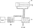
如图5所示的矫形胶输送工具主要包括4个模块:1)注入管;2)主体;3)气动驱动器;4)控制器。下面对每个模块的功能和所包含的元件加以说明。The orthopedic glue delivery tool shown in Figure 5 mainly includes 4 modules: 1) injection tube; 2) main body; 3) pneumatic driver; 4) controller. The functions and components of each module are described below.
1.注入管201.
该管20是使要输送的矫形胶进入病区指定地点的通道,管子20的直径约为1~3mm,优选2~3mm,管子所用材料可以是不锈钢或其它金属或聚合物。该管子的一端通过快速连接器2与主体模块连接。The
此注入管20在输送完矫形胶之后可以扔掉。快速连接器2便于管子20与主体模块的联接和拆卸。一旦完成了矫形胶的输送,通过拧下快速连接器2,就可把注入管子20从其它用于矫形胶固化的大型模块上拆下。可以从管子端部后面插入推杆,以进一步将管子内剩下的矫形胶加到骨腔内。The
2.主体模块2. Main module
此模块分别与注入管20、送料杯4和气动驱动器模块相连接。此模块被固定在把手14上,以使操作员容易完成矫形胶输送任务。矫形胶被事先贮存在送料杯4内,该送料杯4通过快速连接器3安装在主体上的贮存容器40上。在送料杯底座上安放有支承板50和与气体管线11连接的通孔。已加压的空气通过气体管线11提供给送料杯4。所述支承板50则作为送料时对矫形胶施加压力的界面。在支承板50和快速连接器3底座的边缘周围采用密封,以维持送料压力和防止空气泄漏。由气动驱动器推进的矫形胶注入杆30,在容器40底部前后运动,起驱动力的作用以将矫形胶段推入注入管20。注入杆30的长度应这样来选择,在向前冲程中,使杆端部刚好接触注入管20的入口平面。此设计长度可避免当注入器在向后冲程中退回时,注入管子内的矫形胶朝后溢出。为便于矫形胶的进给,送料杯4的内壁可做成适当的形状并/或用不粘材料涂敷。This module is respectively connected with the
3.气动驱动器模块3. Pneumatic drive module
此模块采用气动缸10和方向控制阀13,它们是市场有售的元件。因为气动缸10的冲程杆尺寸通常不同于注入杆30的尺寸,故利用适配器7将气动缸10和注入杆30连在一起,以让动力从空气源传输到要输送的矫形胶。冲程的距离决定了所选的气动缸10模式。为将气动缸10和方向控制阀13牢固地固定在主体上,采用了连接器8和连接器帽9。注意在这种连接器结构两端的连接应该是不漏气的,以保证所需的送料压力。加压空气通过双向连接器12进入气动缸10以及送料杯4中。此压力源可根据打算放置矫形胶的腔体处的反压力来调节。该方向控制阀13是一种电磁阀,该阀可用来控制气动缸10内的空气路径。当空气路径由电磁阀电路选定后,气动缸10的杆将执行向前或向后运动。This module employs a
4.控制器604.
控制器的配置如图6所示。所述控制器60是按照运行要求设计的电路板。目前的控制参数是冲程频率和冲程总数。控制命令可同时通过电路及安装在把手14上的ON/OFF电路扳机15送到方向控制阀13。当按下电路板机15时,将触发控制命令以驱动注入杆30按预先设定的频率和总冲程数前后运动。当电路板机15松开而弹回并切断控制命令时,可按需要停止送料运动。图6中给出了由方向控制阀13控制的空气路径示意图。左边的空气路径是向前推动注入杆的路径,反过来对右边的空气路径也一样。要输送矫形胶的量可用规定的冲程数来校准和确定。但是,送料频率是由反压力和矫形胶的固化时间确定的。一般而言,反压力越高,送料频率越低,因为施加使注入杆运动的力所需的时间将增加。对于硬化快的矫形胶,送料频率应较高,而且空气源的压力应相应提高。The configuration of the controller is shown in Figure 6. The
矫形胶混合器Orthopedic glue mixer
为混合本发明用于矫形或牙科的矫形胶,设计了一种小型电机驱动的活塞式(带密封滑动头)叶轮引发的混合装置。本发明的混合器包括带专门设计的活塞的容器、小型马达、离合器以及罩在与空气供给系统连接的底座内的叶轮。这三种元件可以用适宜的螺丝或快速连接器组装,装拆都很快。专门设计的密封滑动活塞头在混合之前、之中和/或之后可以上/下运动,从而能方便地完成排气和其它功能。For mixing the orthopedic or dental orthopedic glue of the present invention, a small motor-driven piston type (with sealed sliding head) impeller-induced mixing device is designed. The mixer of the present invention comprises a container with a specially designed piston, a small motor, a clutch and an impeller housed in a base connected to an air supply system. These three components can be assembled with suitable screws or quick connectors, and can be assembled and disassembled quickly. The specially designed sealed sliding piston head allows up/down movement before, during and/or after mixing to facilitate venting and other functions.
可用于本发明混合系统的一种优选混合模式,是在加压状态下进行混合(气垫混合)。这是在气垫层下进行的混合。在这种情况下,在混合之前,气垫层保留在骨水泥粉末和固化溶液顶部的容器内。气垫空气压力的一个作用是使溶液的汽化尽可能小,从而使固化延迟(增加骨水泥的工作/固化时间)。A preferred mode of mixing that can be used in the mixing system of the present invention is mixing under pressure (air-cushion mixing). This is the mixing that takes place under the air cushion. In this case, the air cushion remains in the container on top of the bone cement powder and curing solution prior to mixing. One effect of the air cushion air pressure is to minimize the vaporization of the solution, thereby delaying the setting (increasing the working/setting time of the cement).
这种混合过程是利用由高速旋转颤动产生的由叶轮引发的涡旋而完成的。混合一旦结束,混合器就会倒转使已混合的骨水泥胶滴返回到容器内。当气垫层被叶轮再次推进时,该气垫层成为骨水泥刮削器,除了重力和离心作用外,所述气垫层也将粘在叶轮和表面座壁上的骨水泥残余物刮去,这样可以更彻底地收集骨水泥混合物,供随后的输送过程使用(例如,用于注入)。This mixing process is accomplished using impeller-induced vortices produced by high-speed rotating vibrations. Once mixing is complete, the mixer is inverted to return the mixed bone cement drops into the container. When the air cushion is pushed again by the impeller, the air cushion becomes a bone cement scraper, in addition to the gravity and centrifugal force, the air cushion also scrapes off the bone cement residue stuck on the impeller and the surface seat wall, which can be more The bone cement mixture is thoroughly collected for use in subsequent delivery procedures (eg, for injection).
对于包含通过细管将矫形骨水泥胶注入骨腔的矫形外科手术(例如,微创伤脊骨手术),在注入前要将具有适当粉末/液体比的适量骨水泥粉末和凝固溶液混合。混合可以通过手动或利用混合器自动进行。粉末/液体混合物(胶)被迅速输送到用于注入的贮存器/容器内。For orthopedic surgery (eg, minimally invasive spine surgery) that involves injecting orthopedic bone cement into a bone cavity through a thin tube, the appropriate amount of bone cement powder and coagulation solution with an appropriate powder/liquid ratio are mixed prior to injection. Mixing can be performed manually or automatically using a mixer. The powder/liquid mixture (glue) is quickly conveyed into the reservoir/container for infusion.
在混合过程中几乎不可避免地有一定量的空气截留在胶内。截留的空气就像是气泡,并显著地影响骨水泥凝固后的机械性能。为减少截留空气的影响,往往使用或建议使用真空混合法。然而,由于许多固化溶液包含高挥发性液体成分,如果不对过程严加控制,在混合过程和/或胶从混合器输送到贮存器的过程中粉末/液体比可能增加。在这种情况下,真空混合可加速液体成分的挥发,使得胶的粉末/液体比进一步增加,这不仅使注入的胶变得更干和更硬,而且还会改变骨水泥的性质。It is almost inevitable that a certain amount of air will be trapped in the glue during the mixing process. The trapped air acts like air bubbles and significantly affects the mechanical properties of the cement after it has set. To reduce the effects of entrapped air, vacuum mixing is often used or suggested. However, since many curing solutions contain highly volatile liquid components, the powder/liquid ratio may increase during the mixing process and/or during the transfer of the glue from the mixer to the reservoir if the process is not tightly controlled. In this case, vacuum mixing can accelerate the volatilization of liquid components, so that the powder/liquid ratio of the glue can be further increased, which not only makes the injected glue drier and harder, but also changes the properties of the bone cement.
上述粉末/液体比在混合过程和/或骨水泥胶输送过程中改变的问题,可通过采用本发明的混合器设计基本得到解决。本发明的设计可以进行气垫(加压)混合。本发明还可最大限度减少在胶的混合及输送过程中骨水泥胶向外部环境的暴露。另外,此新设计可让混合器迅速而方便地与待注入的任何可混溶骨水泥输送系统的贮存器(贮存室)相连。The aforementioned problems of changing powder/liquid ratios during mixing and/or bone cement delivery are substantially resolved by employing the mixer design of the present invention. The design of the present invention allows air cushion (pressurized) mixing. The invention can also minimize the exposure of the bone cement glue to the external environment during the mixing and delivery of the glue. In addition, this new design allows the mixer to be quickly and easily connected to the reservoir (reservoir) of the delivery system for any miscible bone cement to be injected.
对于本发明的粘合胶的制备,必须注意避免在混合过程中吸收空气。在一种混合器容器中,空气预先存在于固态粉末中或被粉末和固化溶液占据以外的空间中。在气垫混合之前,在固态粉末和固化溶液的顶部保留有一层空气。当混合开始,除了已经吸收在固态粉末内的空气之外,空气进入粘合胶的机会来自发生在空气-流体界面上的淹没运动。在气垫混合中,空气层将被加上由空气供应系统提供的高压。此已加压的空气层可使空气-流体界面更不容易破裂,因此,使该界面在混合过程中更平坦,从而阻止夹杂空气的现象。For the preparation of the adhesive glues according to the invention, care must be taken to avoid the uptake of air during the mixing process. In a mixer vessel, air is pre-existing in the solid powder or in a space other than that occupied by the powder and solidifying solution. A layer of air is retained on top of the solid powder and curing solution prior to air cushion mixing. When mixing begins, in addition to the air already absorbed within the solid powder, the opportunity for air to enter the binder comes from the submerged motion that occurs at the air-fluid interface. In air cushion mixing, the air layer will be subjected to high pressure provided by the air supply system. This pressurized air layer makes the air-fluid interface less prone to rupture, thus making the interface flatter during mixing, thereby preventing air entrapment.
本发明的混合器是一种小型且重量轻的装置,故很容易翻动。完成混合后可以把此混合器装置倒转过来。为便于将骨水泥输送回容器,应在粘合胶和活塞头之间留有足够的空间。重力将使大部分粘合胶落入容器内,同时还有一些残留物粘在混合器叶片和底座壁上。接通马达开关将使混合器叶片在空气层内以高速旋转。被搅动的空气层将起到清洁器的作用,将底座壁上的骨水泥胶吹走。但是,离心力将把粘在叶片上的胶清理干净。因此混合器倒转后使其中大部分骨水泥粘合胶进入容器。可以把该容器拧下并取出安装在任何可混溶的骨水泥输送系统上,供随后使用(例如,用于注入)。The mixer of the present invention is a small and lightweight device, so it is easy to turn over. The mixer unit can be turned upside down after mixing is complete. To facilitate delivery of the bone cement back into the container, there should be sufficient space between the cement and the plunger head. Gravity will cause most of the glue to fall into the container, while some residue will stick to the mixer blades and base walls. Turning on the motor switch will cause the mixer blades to spin at high speed within the air layer. The agitated layer of air will act as a cleaner, blowing away the bone cement from the walls of the abutment. However, centrifugal force will clean the glue that sticks to the blades. Therefore, the mixer is inverted so that most of the bone cement paste enters the container. The container can be unscrewed and removed for mounting on any miscible bone cement delivery system for subsequent use (eg, for injection).
骨水泥的混合和传送过程是在密闭容器内进行,极少暴露于外部环境。如前所述,这样在胶的制备(混合)和输送过程中可减少液体(尤其是高挥发性液体)的蒸发。The mixing and delivery of bone cement takes place in airtight containers with minimal exposure to the outside environment. As mentioned earlier, this reduces the evaporation of liquids (especially highly volatile liquids) during the preparation (mixing) and delivery of the glue.
加压的混合室条件可以让混合过程在较长时间内进行,因而混合更充分。另外,叶轮优选包含4个叶片,而且最优选下双叶片杆和上双叶片杆级联起来,其中相邻叶片具有相反的V形和扭转角,以产生涡旋引发的混合,这样可直接提供高梯度剪切流场,以促使产生非常高效的分子级混合,即动量和质量的传递。The pressurized mixing chamber conditions allow the mixing process to take place over a longer period of time and thus more thoroughly mixed. In addition, the impeller preferably contains 4 blades, and most preferably a lower double blade rod and upper double blade rod are cascaded, where adjacent blades have opposite V-shape and twist angles to create vortex induced mixing, which directly provides High gradient shear flow fields to induce very efficient mixing at the molecular level, ie transfer of momentum and mass.
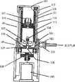
构成本装置有三个基本元件如图7所示。混合器容器140位于该装置顶部。此容器140可用作图5所示输送工具的送料盖4。为避免粘结,采用聚四氟或陶瓷涂敷材料等低摩擦(与骨水泥)材料来做内衬套112。在聚四氟乙烯衬套112和外容器壁111之间加工有使加压空气进入的槽形隐藏沟道118。为将压力加给骨水泥混合物,插入空气密封的活塞114。为完成排气功能,活塞中心体上钻有通孔,该中心体具有用空心紧固件117固定在所述中心体端部的橡胶密封(针状密封短管)116。There are three basic elements constituting the device as shown in Figure 7. A mixer container 140 is located on top of the apparatus. This container 140 can be used as the delivery cap 4 of the delivery tool shown in FIG. 5 . To avoid sticking, a low friction (with bone cement) material such as Teflon or ceramic coating material is used for the
混合机构包括具有轴128的叶轮124,所述轴可旋转地安装在杯120的孔内并用O圈127密封,同时4个叶片125固定在轴的上端。叶片125处于杯120内。轴的下端还与离合器129相连接以在杯120内进行动力传递。通过利用叶轮搅动混合物而将能量传至骨水泥混合物内。所引发的涡旋用作混合机构,其性能主要取决于所选叶轮叶片的结构。杯120具有嵌在金属壳体21内的聚四氟乙烯衬套123。在杯120内的衬套123和壳体121之间加工有环状沟道,所述环状沟道将设在壳体121上的空气口122与容器140的沟道118的出口182联通,以使来自与空气口122连接的空气源的加压空气通过杯120的环状沟道、出口182、沟道118和沟道118的入口181进入容器140。The mixing mechanism includes an
处于混合器底部且具有足够功率和扭矩的电机134,通过与用来传递动力的电机轴相连接的离合器129来驱动叶轮124。A motor 134 at the bottom of the mixer with sufficient power and torque drives the
气垫混合的步骤如下:The steps of air cushion mixing are as follows:
步骤1:将盖113和活塞114从容器140移走,并将该容器拧到杯120上。然后将骨水泥粉末和固化溶液倒进容器140内。Step 1 : Remove the
步骤2:穿过针状密封短管116插入注射器针以排气。将此活塞-针组件滑动推入容器140。当活塞114向下运动时空气将被从针中挤出。通过调节活塞位置在液体表面上方留下适当的空气体积(如3~5c.c.)。Step 2: Insert the syringe needle through the
步骤3:移开排气注射器针和容器盖113上的螺丝。Step 3: Remove the vented syringe needle and the screws on the
步骤4:通过内沟道118送入加压空气以压缩活塞114,并因此使容器140内的压力增加到预定值。Step 4: Send pressurized air through the
步骤5:开启马达134以搅动混合器内的粉末和液体,直至骨水泥胶在混合器内部被充分混合。Step 5: Turn on the motor 134 to agitate the powder and liquid in the mixer until the bone cement is fully mixed in the mixer.
步骤6:倒转(并摇晃)混合器并让已混合的骨水泥胶落入容器140内。Step 6: Invert (and shake) the mixer and let the mixed bone cement drop into the container 140 .
步骤7:再次开启马达134,将留在叶轮124和底座壁上的骨水泥残留物刮入容器140内。Step 7: Turn on the motor 134 again to scrape the bone cement residue left on the
步骤8:从杯120上拧下容器140,并将充满骨水泥胶的容器140安装在用于注入的相应骨水泥输送枪上。Step 8: Unscrew the container 140 from the cup 120 and install the container 140 filled with bone cement glue on the corresponding bone cement delivery gun for injection.
在骨腔内形成硬化骨水泥的方法和装置Method and apparatus for forming hardened bone cement in a bone cavity
在需要通过小手术管往骨腔内注入固体-液体混合矫形骨水泥的矫形手术(例如微创伤脊骨手术)中,可能会出现若干问题。因为这种手术惯用的手术管(导管、注入管等)是端部敞开的,管子通过手术插入患者体内(例如断裂的脊骨结构)之后,患者的血液/体液随即回流并充入管内。In orthopedic procedures (eg, minimally invasive spine surgery) that require the injection of a solid-liquid hybrid orthopedic cement into a bone cavity through a small surgical cannula, several problems may arise. Because the surgical tubes (catheters, infusion tubes, etc.) commonly used in this type of surgery are open-ended, after the tube is surgically inserted into the patient's body (such as a broken spinal structure), the patient's blood/body fluids flow back and fill the tube.
当矫形骨水泥随后注入充满血液/体液的管子时,该胶与血液/体液接触时可能被稀释和/或扩散。胶的稀释伴随着固体/液体比的减小(此比值应保持不变,以确保骨水泥的性能),这可能会显著改变骨水泥的机械性能(如强度)。另外,温暖(体温)的血液/体液可能显著缩短胶的有效时间,以致手术达到无法接收的程度。更糟糕的情况是,该骨水泥一接触血液/体液就立即扩散/分解。这种常见的扩散/分解现象是由于固体和液体混合后,胶中迅速产生的初始强度不足所导致。When the orthopedic cement is subsequently injected into the blood/fluid-filled tube, the glue may become diluted and/or spread upon contact with the blood/fluid. The dilution of the glue is accompanied by a decrease in the solid/liquid ratio (this ratio should be kept constant to ensure the performance of the bone cement), which may significantly change the mechanical properties (such as strength) of the bone cement. Additionally, warm (body temperature) blood/body fluids may significantly shorten the effective time of the glue to an unacceptable degree for surgery. Worse, the bone cement spreads/disintegrates as soon as it comes in contact with blood/body fluids. This common phenomenon of diffusion/disintegration is caused by the lack of initial strength that develops rapidly in the glue after the solid and liquid are mixed.
在牙科和骨科修复中,已经使用各种矫形骨水泥作为植入或填充材料。在骨腔内形成固化/硬化骨水泥的传统方法,是将骨水泥胶直接注入骨腔内,这种方法有以下缺点(当然不止这些):In dental and orthopedic restorations, various orthopedic bone cements have been used as implant or filling materials. The traditional method of forming solidified/hardened bone cement in the bone cavity is to inject the bone cement glue directly into the bone cavity. This method has the following disadvantages (of course not only these):
(i)骨水泥胶的液体-粉末比太高,同时硬化骨水泥的强度太低,这使得骨水泥较容易扩散/分解;(i) The liquid-to-powder ratio of bone cement glue is too high, while the strength of hardened bone cement is too low, which makes the bone cement easier to spread/disintegrate;
(ii)在骨水泥胶的液体-粉末比太低的同时,胶的粘度变得过高,工作和固化时间变得太短,而且该胶很难通过注射器注入。(ii) While the liquid-powder ratio of the bone cement glue is too low, the viscosity of the glue becomes too high, the working and curing time becomes too short, and the glue is difficult to inject through a syringe.
(iii)体液/血液中的散布的骨水泥颗粒,尤其是在完全固化之前,可能渗入周围组织内,这可能会在手术中或之后造成严重危险。(iii) Dispersed bone cement particles in body fluid/blood, especially before complete curing, may infiltrate into surrounding tissue, which may pose a serious hazard during or after surgery.
下面公开了一种在骨腔内形成硬化骨水泥的方法和装置。A method and apparatus for forming hardened bone cement in a bone cavity is disclosed below.
更具体地说,本发明提供一种在骨腔内形成含骨水泥的囊形物的方法和装置。将所述骨水泥胶注入囊形物中可使囊形物膨胀并在骨水泥硬化后按要求碎裂。More specifically, the present invention provides a method and apparatus for forming a cement-containing capsule within a bone cavity. Injection of the bone cement glue into the bladder allows the bladder to expand and disintegrate as desired after the bone cement has hardened.
更具体地说,在骨水泥硬化后囊形物可按预期(指定)方式/模式破裂。More specifically, the capsule can rupture in an expected (specified) manner/pattern after the bone cement has hardened.
囊形物本体优选包含泄漏机构,以使囊形物内胶中所含液体可在压力作用下从囊形物中排出。The bladder body preferably includes a leak mechanism so that the liquid contained in the inner gel of the bladder can be expelled from the bladder under pressure.
本发明克服了上述现有技术中的缺点,因为骨水泥胶是在囊形物内固化而不直接接触体液/血液,同时囊形物内可以产生压力将含在胶中的一部分液体/固化溶液排出囊形物,并大大提高骨水泥的强度,降低骨水泥扩散/分解的危险,而且还可避免骨水泥胶泄漏到周围组织中去。The present invention overcomes the above-mentioned shortcoming in the prior art, because the bone cement glue is solidified in the capsule and does not directly contact body fluid/blood, and pressure can be generated in the capsule to contain a part of the liquid/solidification solution contained in the glue The capsule is discharged, and the strength of the bone cement is greatly improved, the risk of bone cement diffusion/decomposition is reduced, and the leakage of the bone cement glue into the surrounding tissue can also be avoided.
此外,本发明的一个优点是通过监测囊形物内压力的增长,而易于精确地保持骨水泥胶的粉末/液体比,这对于骨水泥的固化时间和强度等特性是很重要的。Furthermore, an advantage of the present invention is that it is easy to precisely maintain the powder/liquid ratio of the bone cement, which is important for characteristics such as setting time and strength of the bone cement, by monitoring the pressure build-up in the capsule.
特别是,这种新发明的囊形物在骨水泥硬化后可以按预定的(指定的)方式(模式)破裂,因此在手术中囊形物的一些随机碎片留在骨腔内的风险最低。In particular, this newly invented capsule can be broken in a predetermined (designated) way (pattern) after the bone cement has hardened, so the risk of some random fragments of the capsule remaining in the bone cavity during surgery is minimal.
本发明的中心思想-穿孔阵列-也可用于“无囊形物”骨水泥输送系统。更具体地说,穿孔阵列思想可用于装置中,以防止在矫形骨水泥胶通过注入管注入骨腔之前,患者的血液/体液进入手术管(导管、注入管等)中。The central idea of the present invention - the perforated array - can also be used in "balloonless" bone cement delivery systems. More specifically, the perforation array concept can be used in devices to prevent the patient's blood/body fluids from entering the surgical tubing (catheter, infusion tube, etc.) before the orthopedic bone cement is injected into the bone cavity through the infusion tube.
囊形物设计(图8和图9)Capsule Design (Figure 8 and Figure 9)
为使囊形物在骨水泥硬化后按预定(设计)方式(模式)破裂,设计了一种穿孔阵列,如图8和9所示的穿孔阵列210。此穿孔阵列主要用来使已膨胀囊形物200按预定破裂线/图形破裂,尽管当孔的尺寸被精心控制时,囊形物中也有渗透效应。穿孔阵列还设计成可使整个破裂囊形物在破裂后保持与注入管相连。如果不是这种设计,已破裂囊形物的某些随机碎片很可能从囊形物脱离并永久留在骨腔内。最理想是整个囊形物在破裂后应保持与注入管连接,并可与管一起被完全拉出来。In order to make the capsule rupture in a predetermined (design) manner (pattern) after the bone cement hardens, a perforation array is designed, such as the
穿孔阵列210的设计图形包括孔、凹痕、压痕、凹槽、切口等,并被制作在囊形物至少一部分的表面上。此类孔、凹痕、压痕、凹槽、切口等可用任何传统方法制成。建议把这些孔、凹痕、压痕、凹槽、切口做在囊形物中心部分或附近。“穿孔线”最好集中在囊形物顶附近,以造成比较脆弱的区域,从该区域开始出现裂痕。The design patterns of the
对于诸如孔的大小、密度、穿孔之间的距离、穿孔阵列数量、和阵列的尺寸等参数,将进行控制和优化,以得到所要求的囊形物结构特性。Parameters such as hole size, density, distance between perforations, number of perforation arrays, and dimensions of the arrays will be controlled and optimized to obtain the desired structural properties of the capsule.
虽然在穿孔阵列的设计中已提供渗透(泄漏)效应,但为了使骨水泥胶被注入并填充骨腔时让水和空气更有效地排出囊形物,在囊形物200的表面上还可设置微孔220。这些微孔可以采用任何传统方法制造,如激光打孔或其它机械方法。这些微孔可随机地或按设定的方式/模式分布,而且随着骨水泥混合物被连续输送到囊形物内而逐渐加大。Although the perforation (leakage) effect has been provided in the design of the perforated array, in order to allow water and air to discharge the capsule more effectively when the bone cement is injected and filled into the bone cavity, there may be additional water and air on the surface of the
囊形物优选用弹性聚合物材料(合成橡胶)制造,其零应力尺寸要足够小,以方便地贮藏在骨水泥注入管内。所述囊形物应具有适当的弹性,使囊形物在压力作用下能和囊形物内的骨水泥胶一起至少膨胀3倍。囊形物厚度应选成当膨胀到预计膨胀体积时仍有足够强度。该已膨胀囊形物应产生适当的张力,使它容易破裂和收缩。但所产生的张力不应太大,以避免囊形物过早破裂。例如,囊形物的制作可采用现有内脉管囊形物导管装置技术,聚胺酯或其它聚合物溶液浇注技术等。The bladder is preferably made of a resilient polymeric material (synthetic rubber) with a zero stress dimension small enough to be conveniently stored within the cement injection tube. The capsule should have proper elasticity, so that the capsule can expand at least 3 times together with the bone cement in the capsule under the action of pressure. The thickness of the balloon should be chosen to be of sufficient strength when inflated to the expected inflated volume. The inflated bladder should develop the proper tension to allow it to rupture and collapse easily. However, the tension generated should not be too great to avoid premature rupture of the capsule. For example, the manufacturing of the balloon can adopt the existing catheter device technology of the inner vessel balloon, polyurethane or other polymer solution casting technology, and the like.
随着骨水泥混合物被输送至填充骨腔并在尺寸上膨胀,囊形物表面将约束骨水泥,同时迫使一部分空气和水通过上述在制造过程中含有的大量微孔和穿孔排出囊形物。该骨水泥填充过程可以认为是一个静态力平衡问题。基本上牵涉到三种力。首先是骨压力,即在破裂的脊骨内的压力。如无体重压缩,骨压力近似等于大气压力。As the cement mixture is delivered to fill the bone cavity and expands in size, the surface of the capsule will bind the bone cement while forcing a portion of the air and water out of the capsule through the aforementioned numerous pores and perforations contained in the manufacturing process. The cement filling process can be considered as a static force balance problem. Basically three forces are involved. The first is bony stress, the pressure within a ruptured spine. Without body weight compression, bone pressure is approximately equal to atmospheric pressure.
其次是在囊形物内部的压力,或所谓的腔体压力,它由骨压力和随着膜膨胀而变形的表面共面张应力确定。囊形物材料强度越大,骨压力和腔体压力之差越大。此压力差在将空气和/或水挤出囊形物中起主要作用。因此,在设计囊形物模件时,选择适当的弹性体强度和预定的微孔尺寸和孔隙度,可能决定骨水泥混合物脱水的有效程度。Second is the pressure inside the capsule, or the so-called cavity pressure, which is determined by the bone pressure and the surface coplanar tensile stress that deforms as the membrane expands. The stronger the bladder material, the greater the difference between bone pressure and cavity pressure. This pressure differential plays a major role in forcing air and/or water out of the bladder. Therefore, when designing a bladder module, selection of the appropriate elastomer strength and predetermined cell size and porosity may determine how effectively the bone cement mixture is dehydrated.
第三,是由骨水泥输送系统压力源提供的输送压力。通常只要水通过微孔的输送速度很慢,输送压力和腔体压力就是相等的。The third is the delivery pressure provided by the pressure source of the bone cement delivery system. Usually as long as the water delivery rate through the pores is slow, the delivery pressure and cavity pressure are equal.
随着囊形物在碎裂的脊骨上膨胀,将随囊形物鼓起而产生共面的膜应力。此膜应力可能使囊形物产生较高的内部压力,这就是在基本保留囊形物瓤内骨水泥固体部分的同时,将空气和液体(与骨水泥相比,它们的分子量和尺寸要小得多)逐出腔体空间的主要机理。脱水自然与骨水泥输送过程有关,而且柔性囊形物材料将有助于骨水泥填充与增大的内部骨空间形状共形的空间。As the bladder expands over the fragmented spine, coplanar membrane stresses will be created as the bladder bulges. This membrane stress may cause the capsule to generate a higher internal pressure, which is to draw air and liquid (which are smaller in molecular weight and size compared to bone cement) while substantially retaining the solid part of the bone cement in the capsule pulp. Much more) the primary mechanism for expulsion from cavity space. Dehydration is naturally related to the cement delivery process, and the flexible bladder material will help the cement fill the space that conforms to the shape of the enlarged internal bone space.
虽然囊形物的内部空间被支撑囊形物形态的骨水泥胶紧密填充,但在开始注入骨水泥之前还要选择合适的囊形物尺寸。对于不同的患者或情况,估计应该输送多少骨水泥,需要事先利用X光等适当的仪器来决定。当选定的囊形物膨胀到设计好的体积时,膜应力的大小应该足以在注入和脱水过程中将骨水泥固定在适当位置,同时保持囊形物在适当的安全范围内破裂。这种绷紧状态,将为以后加上附加力把囊形物拔出骨腔时,囊形物容易破裂作好准备。Although the internal space of the capsule is tightly packed with the bone cement that supports the morphology of the capsule, it is important to select the proper capsule size before starting to inject the bone cement. For different patients or situations, the estimation of how much bone cement should be delivered needs to be determined in advance using appropriate instruments such as X-rays. When the selected capsule is inflated to the designed volume, the magnitude of the membrane stress should be sufficient to hold the bone cement in place during injection and dehydration while keeping the capsule rupture within an appropriate safety margin. This tense state will make preparations for the easy rupture of the capsule when additional force is applied to pull the capsule out of the bone cavity.
对于不同的要输送的骨水泥体积应采用一系列囊形物尺寸。这些囊形物的主要差别在于其长度和厚度,因为横向尺寸被限制为相同,以使囊形物能被贮存在骨水泥输送管的远端内。管子尺寸(直径优选小于5mm,更优选小于3mm)和最终膨胀后的腔体尺寸将决定囊形物材料所需的延伸率。这个延伸率又将决定囊形物应具有怎样的工作弹性范围。此外,由于弹性体是按可以得到囊形物所要求的伸长来选择的,应该仔细考虑穿孔的尺寸、位置和孔隙度,以使在最后排出步骤中,囊形物依照其不同的尺寸更容易破裂。A range of capsule sizes should be used for different cement volumes to be delivered. The primary difference between these bladders is their length and thickness, since the transverse dimensions are constrained to be the same, so that the bladders can be stored within the distal end of the bone cement delivery tube. The size of the tube (preferably less than 5 mm in diameter, more preferably less than 3 mm) and the final inflated lumen size will determine the required elongation of the balloon material. This elongation, in turn, will determine the range of operating elasticity that the bladder should have. Furthermore, since the elastomer is chosen to achieve the desired elongation of the bladder, careful consideration should be given to the size, location and porosity of the perforations so that during the final expulsion step the bladder is more flexible according to its different dimensions. Easy to break.
膨胀了的囊形物将破裂并缩回到它原来的零应力状态。这种破裂自动构成囊形物的提取功能。囊形物内的张力越高,囊形物破裂和回提越有效。不过,必须注意避免产生过大的张力,这样可能促使囊形物在骨水泥输送期间由于接触骨腔的粗糙表面而过早产生不希望的破裂。The inflated bladder will rupture and retract to its original zero stress state. This rupture automatically constitutes the extraction function of the capsule. The higher the tension within the capsule, the more efficient the capsule ruptures and pulls back. However, care must be taken to avoid excessive tension, which may promote premature and undesired rupture of the capsule due to contact with the rough surface of the bone cavity during cement delivery.
对被输送的骨水泥加压有两个主要作用,这是本方法的特征。第一个作用是使已破裂的骨结构膨胀到某种希望的形状和尺寸。通过骨水泥胶的流体运动,压力可以传递到使骨水泥紧密地填充在骨腔内,与此同时促使骨结构恢复到它的原来形状和尺寸。第二,在骨水泥加压过程中,骨水泥的一部分空气和液体/固化溶液可以被挤出囊形物。Pressurization of the delivered bone cement has two main effects that characterize the method. The first function is to expand the fractured bone structure to a certain desired shape and size. Through the fluid movement of the bone cement glue, pressure can be transmitted to make the bone cement tightly fill the bone cavity, and at the same time cause the bone structure to return to its original shape and size. Second, during cement pressurization, a portion of the cement's air and liquid/setting solution can be forced out of the capsule.
加压和液体分离将有助于骨水泥的固化,这对于骨水泥在囊形物内硬化时形成一定结构和强度是很关键的。Pressurization and liquid separation will aid in the setting of the bone cement, which is critical for the bone cement to develop structure and strength as it hardens within the capsule.
骨水泥的输送过程如下面所述:The bone cement delivery process is as follows:
步骤1step 1
在患病的脊骨上钻一个通孔,形成圆柱腔体。估计要输送的骨水泥体积。在利用管子和注入器插头如图5所示的出口管20和注入杆30等将适量的骨水泥胶输送到骨腔内之前,用安装机构将囊形物连至注入管(最好是圆柱形)的注入端,例如,所述安装机构具有设置在管子外表面上的环形槽以及适用于弹性夹紧所述环形槽的圆环。将圆柱管的注入端插入囊形物的开口内,使得囊形物的颈部盖住该环形槽,同时将此圆环(闭合圆环或C形环)推到囊形物颈部,并将它夹紧在管子的环形槽上。这种包含环形槽和圆环的安装机构,与美国专利申请出版物N0.2004/0186481A1所述的安装机构相似,后者被引用于此作为参考。A hole is drilled through the diseased spine, creating a cylindrical cavity. Estimate the volume of bone cement to be delivered. Before utilizing the
步骤2
通过以预先校准过的压力(优选约为1~5000psi,更优选为10~1000psi)来推动注入器插头压缩骨水泥胶使囊形物膨胀,直至已损坏的骨头膨胀到所希望的形状和尺寸,这里一部分液体和空气通过泄漏机构从骨水泥胶中排出。仅在骨水泥的输送后期水/空气的排出才会显著发生,因为在输送后期膜内产生了共面应力而引起的压力差,从而将水/空气排出。Compress the bone cement by pushing the injector plug at a pre-calibrated pressure (preferably about 1-5000 psi, more preferably 10-1000 psi) to expand the capsule until the damaged bone expands to the desired shape and size , here part of the liquid and air is expelled from the bone cement through the leakage mechanism. Water/air evacuation only occurs significantly later in the delivery of the bone cement because of pressure differentials induced by coplanar stresses in the membrane during the latter stages of delivery, thereby evacuating water/air.
步骤3step 3
仔细调节已膨胀的腔体尺寸(注意:考虑到由于漏水和骨水泥泄漏造成的体积损失,可能需要微调。可采用X光或其它监视设备来监视此过程)。利用适当的背压支托注入杆。对骨水泥胶加压一定时间,直至骨水泥在囊形物内硬化。Carefully adjust the expanded cavity size (Note: Minor adjustments may be required to account for volume loss due to water and cement leakage. X-ray or other monitoring equipment may be used to monitor this process). Support injection rod with proper back pressure. The cement paste is pressurized for a period of time until the cement hardens within the capsule.
步骤4step 4
将所述注入器管以及囊形物向外(同时让注入器杆保持固定)拔出,并使囊形物从顶部开始沿所设计的穿孔线破裂。在相对于腔体出口托住注入器插头直至囊形物清理好出口的同时,抽出已破裂的囊形物。从病人体内抽出整个输送系统。The injector tube and balloon were pulled outwards (while keeping the injector stem fixed) and the balloon was ruptured from the top along the designed perforation line. Withdraw the ruptured balloon while holding the injector plug against the cavity outlet until the balloon clears the outlet. Withdraw the entire delivery system from the patient.
用来防止液体进入手术管的装置和方法Device and method for preventing fluid from entering surgical tubing
在需要通过小手术管往骨腔内注入固体-液体混合矫形骨水泥的矫形手术(例如微创伤脊骨手术)中,可能会发生若干问题。因为这种手术惯用的手术管(导管、注入管等)是端部敞开的,管子通过手术插入病人体内(例如断裂的脊骨结构)之后,病人的血液/体液随即回流并充入管内。当矫形骨水泥随后注入充满血液/体液的管子时,胶与血液/体液接触时可能被稀释和/或扩散。胶的稀释伴随着固体/液体比的减小(此比值应保持不变,以确保骨水泥的性能),这可能会显著改变骨水泥的机械性能(如强度)。另外,温暖的(体温)血液/体液可能显著缩短胶的有效时间,以致手术无法接收的程度。更糟糕的情况是,骨水泥胶一接触血液/体液就立即扩散/分解。由于固体和液体混合后起始强度不足的情况在胶中迅速扩大,这种扩散/分解较常见。In orthopedic procedures (eg, minimally invasive spinal surgery) that require the injection of a solid-liquid hybrid orthopedic cement into a bone cavity through a small surgical cannula, several problems may arise. Because the surgical tubes (catheters, infusion tubes, etc.) commonly used in this operation are open-ended, after the tube is inserted into the patient's body (such as a broken spinal structure), the patient's blood/body fluid immediately returns and fills the tube. When the orthopedic cement is subsequently injected into the blood/fluid-filled tube, the glue may become diluted and/or spread upon contact with the blood/fluid. The dilution of the glue is accompanied by a decrease in the solid/liquid ratio (this ratio should be kept constant to ensure the performance of the bone cement), which may significantly change the mechanical properties (such as strength) of the bone cement. Additionally, warm (body temperature) blood/body fluids may significantly shorten the effective time of the glue to an extent that is unacceptable for surgery. Even worse, the bone cement spreads/disintegrates as soon as it comes into contact with blood/body fluids. This diffusion/disintegration is more common due to the rapid expansion in the glue of insufficient initial strength after the solid and liquid are mixed.
下面介绍用来防止液体进入手术管的装置和方法。更具体地说,所公开的装置和方法,是为了防止患者的血液/体液在矫形骨水泥胶用注入管注入骨腔之前进入手术管(导管、注入管等)内。Devices and methods for preventing fluid from entering surgical tubing are described below. More specifically, the disclosed devices and methods are designed to prevent the patient's blood/body fluid from entering the surgical tube (catheter, injection tube, etc.) before the orthopedic bone cement is injected into the bone cavity through the injection tube.
前面提到的缺点,可通过把本发明的装置应用在管子的前(引导)端或其附近而基本克服,此装置可防止病人血液/体液进入该管,还允许骨水泥胶在胶注入过程中穿过(破坏)该装置。The aforementioned disadvantages can be substantially overcome by applying the device of the present invention at or near the front (leading) end of the tube, which prevents the patient's blood/body fluids from entering the tube and also allows the bone cement to be used during the glue injection process. penetrate (destroy) the device.
如图10和11所示,该装置310可以是防水的聚合物薄膜,其强度(与用来制造薄膜的材料的固有强度、薄膜厚度等有关)被调整得足够高,以抵挡内部从病人血液/体液施加的压力,而同时又足够脆弱,使注入的胶不费力地破坏该薄膜并进入骨腔内。这种薄膜可采用任何传统的聚合物材料并用传统方法制备。可以用任何传统的方法将薄膜与手术管300的管端相连接。As shown in Figures 10 and 11, the
建议在至少部分薄膜表面上制出凹痕、凹坑、凹槽、切口等图形320。最好把这些凹痕、凹坑、凹槽、切口等制作在薄膜中心部分或其附近。这些凹痕、凹坑、凹槽、切口等是设计用来帮助注入胶破坏薄膜的过程,并使破裂后的薄膜碎片仍然保持与管端(边界/边缘)相连。如果不是这种设计,薄膜碎片可能变成很多小块混进胶内进入骨腔。最理想是整个薄膜在破裂后应保持与管连接,而且可以在胶注入后和管子一起全部抽出。It is proposed to make
薄膜中还可能有多个微孔(细孔/穿孔)。这些细孔足够小以可防止水(血液/体液)穿过,然而又足够大以允许空气通过。这种可透气而不透水的微孔/细孔设计,可防止在骨水泥胶注入过程中管内(前端)空气压力的增长。这种管内(在注入胶前面)空气压力的增长可造成注入困难(受到阻力),或者甚至导致薄膜过早(在注入胶到达薄膜之前)破裂。不渗透液体的薄膜的存在也有助于维持胶内的粉末/液体比不变。如前面所述,恒定的粉末/液体比对骨水泥的性能是关键的。微孔可以用任何传统方法制备。There may also be multiple pores (pores/perforations) in the film. These pores are small enough to prevent the passage of water (blood/body fluids), yet large enough to allow the passage of air. This air-permeable and impermeable micropore/fine-pore design can prevent the increase of air pressure inside the tube (front end) during bone cement injection. This increase in air pressure in the tube (before the injectant) can cause injection difficulties (resistance), or even cause premature (before the injectant reaches the membrane) rupture of the membrane. The presence of a liquid-impermeable film also helps to maintain a constant powder/liquid ratio within the gel. As mentioned previously, a constant powder/liquid ratio is critical to bone cement performance. Microwells can be prepared by any conventional method.
优选用生物相容的聚合物材料来制备薄膜。最优选用生物相容的和可生物降解的聚合物材料来制备。这是基于如下的考虑:万一有些薄膜碎片/小块脱落被带入骨腔内,生物相容的和可生物降解的聚合物材料将比其它材料更安全。可以选用许多现有的生物相容的和可生物降解的聚合物材料。The film is preferably prepared from a biocompatible polymeric material. Most preferably they are made of biocompatible and biodegradable polymeric materials. This is based on the consideration that biocompatible and biodegradable polymer materials will be safer than other materials in case some film fragments/pieces break off and are carried into the bone cavity. Many existing biocompatible and biodegradable polymeric materials can be used.
装置310也可以是与管300前端相连接的单向盖/阀。这种单向盖可防止血液/体液进入管内,而同时又可让注入胶打开并通过此盖进入骨腔内。该盖可用金属或聚合物制成,并可通过任何传统方法与管子连接。
使骨腔膨胀的装置和方法Devices and methods for dilating a bone cavity
治疗粉碎性骨结构患者(例如在脊骨体内的压缩性碎裂),往往是首先将碎裂的骨结构修复(膨胀)成它原来的结构(形状和尺寸)。接着将矫形骨水泥胶注入至已膨胀(且往往是多孔性)的骨腔。已硬化/固化的骨水泥为正在愈合的骨结构提供额外的强度。Treatment of patients with comminuted bone structures (eg, compressive fractures in the vertebral body) often begins with repairing (expanding) the fractured bone structure to its original configuration (shape and size). Orthopedic cement is then injected into the expanded (and often porous) bone cavity. Hardened/cured bone cement provides additional strength to the healing bone structure.
传统使用的是聚合物囊形物,所述囊形物在植入破裂的骨结构后可通过把液体(如水)压入瓶中而使囊形物膨胀。在该囊形物膨胀到所需尺寸后,排出液体并将囊形物从腔体拔出。然后矫形骨水泥胶注入已膨胀的腔体中。Traditionally, polymeric bladders have been used which can be inflated by pressing a liquid, such as water, into a bottle after implantation into a ruptured bone structure. After the balloon is inflated to the desired size, the fluid is drained and the balloon is pulled out of the lumen. Orthopedic cement is then injected into the expanded cavity.
聚合物囊形物用在这类治疗上的一个固有问题是,囊形物材料例如如常用的PU材料具有相对低的硬度和强度。在囊形物膨胀过程中,当偶尔碰到周围不规则形状的骨碎片时,已膨胀的聚合物囊形物会发生破裂。这种囊形物方法的另一个潜在问题是,“软”囊形物有时可能会被骨碎片“俘获”(缠住),这会妨碍囊形物从骨腔内抽出。An inherent problem with the use of polymeric capsules for this type of treatment is that the capsule material, eg PU material as commonly used, has relatively low stiffness and strength. During balloon expansion, the expanded polymeric balloon ruptures when it occasionally encounters surrounding irregularly shaped bone fragments. Another potential problem with this capsule approach is that the "soft" capsule can sometimes become "captured" (entangled) by bone fragments, which can prevent extraction of the capsule from the bone cavity.
通过采用本发明用于膨胀破裂的骨结构的装置/方法能够基本克服上面这些关于囊形物方法的问题,如下所述。These above problems with the balloon approach can be substantially overcome by employing the device/method of the present invention for dilating a ruptured bone structure, as described below.
本发明的装置包含非常柔软的腔体填充物,该填充物能很容易地插入骨腔内并从骨腔中抽出。与囊形物方法不同,在膨胀过程中,本发明的填充物不充气(膨胀)或未填充液体,这有效地克服了关于囊形物方法的上述问题。骨腔的膨胀水平(程度)通过插入骨腔的填充物的体积来控制。The device of the present invention comprises a very soft cavity filler which can be easily inserted into and withdrawn from the bone cavity. Unlike the bladder approach, the filler of the present invention is not inflated (inflated) or filled with liquid during inflation, which effectively overcomes the above-mentioned problems with the bladder approach. The level (degree) of expansion of the bone cavity is controlled by the volume of filler inserted into the bone cavity.
这种填充物可以用非常有弹性的丝制成。丝填充物可以用聚合物或金属制成,其直径大约为0.1mm~5mm,优选为大约1mm~3mm。由于非常柔软,当丝碰到骨腔壁时很容易在骨腔内弯折。随着所插入丝的体积(或长度)增加,骨腔膨胀并被扭曲(弯折)的丝“填充”。可以通过手术管将丝导入,并可通过给丝加压来帮助丝的导入。这样可将丝连到柱子(杆)上,然后将柱子推进管内。当达到所需的腔体体积时,将柱子连同与它相连的丝一起从管中抽出。This stuffing can be made from very stretchy silk. The silk filler can be made of polymer or metal, and its diameter is about 0.1 mm to 5 mm, preferably about 1 mm to 3 mm. Being very soft, the wire bends easily in the bone cavity when it hits the bone cavity wall. As the volume (or length) of the inserted wire increases, the bone cavity expands and is "filled" with the twisted (bent) wire. The wire can be introduced through a surgical tube and can be assisted by applying pressure to the wire. This attaches the wire to the post (rod), which is then pushed into the tube. When the desired lumen volume is reached, the column is withdrawn from the tube along with the wire attached to it.
本发明中的填充物也可以通过将多个物体如珠子连接成非常易弯折的“项链”而制成。这些珠子可由金属或聚合物制成,可以是刚性的或柔软的,而且可以采用任何传统的方法诸如用来制造项链的方法连接在一起。The stuffing of the present invention can also be made by linking multiple objects such as beads into a very flexible "necklace". The beads can be made of metal or polymer, rigid or flexible, and can be joined together by any conventional means such as those used to make necklaces.
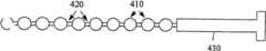
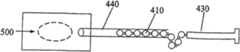
珠子可以是任何形状,但最好是球形,以减少填充物在插入和抽出过程中的摩擦。如图12所示,同样尺寸的球状珠410通过丝420连接在一起,其中一根丝420与柱子430相连接。珠410和丝420构成填充物,而销430起支托填充物的作用。可以把不同尺寸的珠子组合形成“项链”。例如图13所示,把大珠410a和小珠410b交替连接(可以把一个小珠放在每两个大珠之间)。The beads can be of any shape, but are preferably spherical to reduce friction of the filler during insertion and withdrawal. As shown in FIG. 12 ,
每单个珠子的直径大约为0.1mm~5mm,优选为大约1mm~3mm。相邻两珠的距离不应太大,以防各珠缠住,珠子缠住可能会妨碍珠子从管中抽出。具体地说,两相邻珠间的距离应小于珠子的直径,最好是小于珠子直径的一半。The diameter of each individual bead is about 0.1 mm to 5 mm, preferably about 1 mm to 3 mm. The distance between two adjacent beads should not be too large to prevent the beads from getting entangled, which may prevent the beads from being extracted from the tube. Specifically, the distance between two adjacent beads should be less than the diameter of the bead, preferably less than half the diameter of the bead.
骨腔的膨胀水平(程度)由插入骨腔的珠填充物(“项链”)的体积控制。当“项链”碰到骨腔壁时,很容易在骨腔中弯折。随着被插入的珠子体积(或数量)的增加,骨腔膨胀并被珠子“填充”。如图14至17所示,可通过手术管440的引导并可通过将柱子430推入管400中而对珠410加压来帮助将珠子填充物插入骨腔500中。当达到所需腔体体积时,柱子430连同与它相连的“项链”一起从管440抽出。The level (degree) of expansion of the bone cavity is controlled by the volume of bead filler ("necklace") inserted into the bone cavity. When the "necklace" hits the wall of the bone cavity, it is easy to bend in the bone cavity. As the volume (or number) of beads inserted increases, the bone cavity expands and "fills" with the beads. Insertion of the bead filler into
在膨胀压缩碎片脊柱体骨结构中使用样机“项链”装置的初步临床实验结果证明,这种新构思/装置的效果不错。Preliminary clinical trial results using a prototype "necklace" device in expanding and compressing fragmented spinal body bone structures demonstrated that this new concept/device works well.
Claims (18)
Translated fromChineseApplications Claiming Priority (4)
| Application Number | Priority Date | Filing Date | Title |
|---|---|---|---|
| US11/152,170US7325702B2 (en) | 2005-06-15 | 2005-06-15 | Orthopaedic paste delivering tool and method for continually delivering the paste |
| US11/152,170 | 2005-06-15 | ||
| US60/713,851 | 2005-09-02 | ||
| US60/763,134 | 2006-01-30 |
Publications (2)
| Publication Number | Publication Date |
|---|---|
| CN101247765A CN101247765A (en) | 2008-08-20 |
| CN100569193Ctrue CN100569193C (en) | 2009-12-16 |
Family
ID=37572374
Family Applications (1)
| Application Number | Title | Priority Date | Filing Date |
|---|---|---|---|
| CNB2006800214593AExpired - Fee RelatedCN100569193C (en) | 2005-06-15 | 2006-06-14 | Tool and method for continuous delivery of orthopaedic paste |
Country Status (2)
| Country | Link |
|---|---|
| US (1) | US7325702B2 (en) |
| CN (1) | CN100569193C (en) |
Families Citing this family (9)
| Publication number | Priority date | Publication date | Assignee | Title |
|---|---|---|---|---|
| NL1034895C2 (en)* | 2008-01-08 | 2009-07-13 | Dispensing Technologies Bv | Composite container and method for manufacturing thereof. |
| EP2450064B1 (en) | 2010-10-19 | 2014-04-09 | National Cheng Kung University | Bone Cement Formula and Bioresorbable Hardened Bone Cement Composites Prepared with the Same |
| US9101429B2 (en)* | 2011-04-27 | 2015-08-11 | Jiin-Huey Chern Lin | Method and apparatus for delivering cement paste into a bone cavity |
| TWI439298B (en) | 2011-11-28 | 2014-06-01 | Univ Nat Cheng Kung | Calcium-based bone cement formula with enhanced non-dispersive ability |
| CN102835995B (en)* | 2012-09-17 | 2015-07-29 | 浙江微度医疗器械有限公司 | A kind of bone cement fill balloon-system |
| US9445918B1 (en) | 2012-10-22 | 2016-09-20 | Nuvasive, Inc. | Expandable spinal fusion implants and related instruments and methods |
| CN111568528A (en)* | 2020-06-22 | 2020-08-25 | 南京鼓楼医院 | A bone cement electric propelling gun |
| CN112741677B (en)* | 2020-12-30 | 2022-02-08 | 北京铸正机器人有限公司 | Bone cement injection device |
| CN114524403B (en)* | 2022-02-18 | 2024-01-23 | 华能新疆能源开发有限公司新能源东疆分公司 | Electric oiling tool for reduction gearbox |
Citations (5)
| Publication number | Priority date | Publication date | Assignee | Title |
|---|---|---|---|---|
| US4671263A (en)* | 1984-07-11 | 1987-06-09 | Klaus Draenert | Device and process for mixing and applying bone cement |
| US5816455A (en)* | 1994-05-27 | 1998-10-06 | Specialty Equipment Companies, Inc. | Method and apparatus for frozen dessert dispensing |
| US20020058947A1 (en)* | 2000-02-28 | 2002-05-16 | Stephen Hochschuler | Method and apparatus for treating a vertebral body |
| US20030032964A1 (en)* | 2001-02-15 | 2003-02-13 | Neil Watkins | Vertebroplasty bone cement |
| US20040196735A1 (en)* | 2002-10-07 | 2004-10-07 | Donald Barker | Apparatus for mixing and dispensing components |
Family Cites Families (4)
| Publication number | Priority date | Publication date | Assignee | Title |
|---|---|---|---|---|
| IT1206884B (en)* | 1987-02-02 | 1989-05-11 | Eltek Spa | DISPENSING DEVICE OF LIQUIDS IN PRESTABLE AND CONSTANT VOLUMES INDEPENDENTLY FROM THE PRESSURE AND THE CAPACITY OF THE SUPPLY SOURCE OF THE DISPENSED LIQUID |
| FR2641608B1 (en)* | 1989-01-06 | 1991-04-26 | Unisabi Sa | MEASURING DEVICE FOR PASTY PRODUCTS, ESPECIALLY MEAT EMULSIONS OR OTHER PROTEINS |
| JP2591744Y2 (en)* | 1993-01-20 | 1999-03-10 | ノードソン株式会社 | Dispenser for liquid discharge with liquid enclosing cartridge storage case |
| US5816445A (en)* | 1996-01-25 | 1998-10-06 | Stainless Steel Coatings, Inc. | Method of and apparatus for controlled dispensing of two-part bonding, casting and similar fluids and the like |
- 2005
- 2005-06-15USUS11/152,170patent/US7325702B2/enactiveActive
- 2006
- 2006-06-14CNCNB2006800214593Apatent/CN100569193C/ennot_activeExpired - Fee Related
Patent Citations (5)
| Publication number | Priority date | Publication date | Assignee | Title |
|---|---|---|---|---|
| US4671263A (en)* | 1984-07-11 | 1987-06-09 | Klaus Draenert | Device and process for mixing and applying bone cement |
| US5816455A (en)* | 1994-05-27 | 1998-10-06 | Specialty Equipment Companies, Inc. | Method and apparatus for frozen dessert dispensing |
| US20020058947A1 (en)* | 2000-02-28 | 2002-05-16 | Stephen Hochschuler | Method and apparatus for treating a vertebral body |
| US20030032964A1 (en)* | 2001-02-15 | 2003-02-13 | Neil Watkins | Vertebroplasty bone cement |
| US20040196735A1 (en)* | 2002-10-07 | 2004-10-07 | Donald Barker | Apparatus for mixing and dispensing components |
Also Published As
| Publication number | Publication date |
|---|---|
| US7325702B2 (en) | 2008-02-05 |
| CN101247765A (en) | 2008-08-20 |
| US20060283890A1 (en) | 2006-12-21 |
Similar Documents
| Publication | Publication Date | Title |
|---|---|---|
| CN100569193C (en) | Tool and method for continuous delivery of orthopaedic paste | |
| KR100948082B1 (en) | Tools and techniques for the continuous delivery of orthopedic pastes | |
| US10039584B2 (en) | System for use in bone cement preparation and delivery | |
| JP6564095B2 (en) | Devices for storage, mixing and injection of bone cement and related methods | |
| US8357169B2 (en) | System and method for delivering an agglomeration of solid beads and cement to the interior of a bone in order to form an implant within the bone | |
| US8409212B2 (en) | Perforated balloon and method for forming a hardened orthopaedic paste in a bone using same | |
| RU2414256C2 (en) | High-viscosity material injection device | |
| US6086594A (en) | Cement pressurizing device | |
| US8777479B2 (en) | System for use in bone cement preparation and delivery | |
| JP6563978B2 (en) | Storage and mixing device for bone cement with pressure pump | |
| JP2018143762A (en) | Storing and mixing apparatus having two product construction for bone cement product and relating method | |
| CN101163461A (en) | Methods, materials and devices for treating bone and other tissues | |
| US10765464B2 (en) | Bone cement mixing device with spacer in an ampoule receptacle | |
| CA3044592C (en) | Bone cement applicator with retractable mixing rod and method for production of a bone cement | |
| CN109747041A (en) | Powder-liquid bone cement mixer with compressed gas connection | |
| US20230310048A1 (en) | Device and method for providing bone cement paste | |
| EP2029038B1 (en) | System for delivering an agglomeration of solid beads and cement to the interior of a bone in order to form an implant within the bone | |
| US20050013805A1 (en) | Device and method for delivery of rapidly separating body of fluid, forming bone reconstruction medium | |
| US5951563A (en) | Sensor system for flowable cement | |
| EP2005909A9 (en) | Device for vertebral repair | |
| EP2190360B1 (en) | Bone cavity creation system with magnetic force retrievable beads |
Legal Events
| Date | Code | Title | Description |
|---|---|---|---|
| C06 | Publication | ||
| PB01 | Publication | ||
| C10 | Entry into substantive examination | ||
| SE01 | Entry into force of request for substantive examination | ||
| C14 | Grant of patent or utility model | ||
| GR01 | Patent grant | ||
| ASS | Succession or assignment of patent right | Owner name:BAZHALIER CO., LTD Free format text:FORMER OWNER: LU PENGJU Effective date:20100309 Free format text:FORMER OWNER: CHEN JINHUI ZHU JIANPING | |
| C41 | Transfer of patent application or patent right or utility model | ||
| COR | Change of bibliographic data | Free format text:CORRECT: ADDRESS; FROM: 8F-4, NO.88, 3RD SECTION, CHANGRONG ROAD, TAINAN CITY, TAIWAN PROVINCE, CHINA TO: ILLINOIS, U.S.A. | |
| TR01 | Transfer of patent right | Effective date of registration:20100309 Address after:Illinois Patentee after:Are you a limited liability company Address before:Taiwan, Tainan, China three 88 paragraph EVA Road, 8F-4 Patentee before:Lu Pengju Patentee before:Chen Jinhui Patentee before:Zhu Jianping | |
| ASS | Succession or assignment of patent right | Owner name:XILE MEDICAL EQUIPMENT CO., LTD. Free format text:FORMER OWNER: BAZHA LI'ER CO., LTD. Effective date:20110819 | |
| C41 | Transfer of patent application or patent right or utility model | ||
| COR | Change of bibliographic data | Free format text:CORRECT: ADDRESS; TO: TAIWAN, CHINA | |
| TR01 | Transfer of patent right | Effective date of registration:20110819 Address after:Kaohsiung City, Taiwan, China Patentee after:Xile Medical Equipment Co., Ltd. Address before:Illinois Patentee before:Are you a limited liability company | |
| CF01 | Termination of patent right due to non-payment of annual fee | Granted publication date:20091216 Termination date:20200614 | |
| CF01 | Termination of patent right due to non-payment of annual fee |