Movatterモバイル変換


[0]ホーム

URL:


CN100569174C - Electronic endoscope - Google Patents

Electronic endoscope
Download PDF

Info

Publication number
CN100569174C
CN100569174CCNB2005800154009ACN200580015400ACN100569174CCN 100569174 CCN100569174 CCN 100569174CCN B2005800154009 ACNB2005800154009 ACN B2005800154009ACN 200580015400 ACN200580015400 ACN 200580015400ACN 100569174 CCN100569174 CCN 100569174C
Authority
CN
China
Prior art keywords
mentioned
optical system
electronic endoscope
signal
black
Prior art date
Legal status (The legal status is an assumption and is not a legal conclusion. Google has not performed a legal analysis and makes no representation as to the accuracy of the status listed.)
Expired - Lifetime
Application number
CNB2005800154009A
Other languages
Chinese (zh)
Other versions
CN1953697A (en
Inventor
粂井一裕
加藤贵之
Current Assignee (The listed assignees may be inaccurate. Google has not performed a legal analysis and makes no representation or warranty as to the accuracy of the list.)
Olympus Corp
Original Assignee
Olympus Corp
Olympus Medical Systems Corp
Priority date (The priority date is an assumption and is not a legal conclusion. Google has not performed a legal analysis and makes no representation as to the accuracy of the date listed.)
Filing date
Publication date
Application filed by Olympus Corp, Olympus Medical Systems CorpfiledCriticalOlympus Corp
Publication of CN1953697ApublicationCriticalpatent/CN1953697A/en
Application grantedgrantedCritical
Publication of CN100569174CpublicationCriticalpatent/CN100569174C/en
Anticipated expirationlegal-statusCritical
Expired - Lifetimelegal-statusCriticalCurrent

Links

Images

Landscapes

Abstract

The invention provides an electronic endoscope. The electronic endoscope is provided with a channel in which a treatment instrument can be inserted in an insertion portion, an objective optical system with a single focus or a variable focus position is provided at a distal end portion of the insertion portion, and an optical image is formed on a light receiving surface of an image pickup element. In this state, the distal end side of the treatment instrument, which projects from the distal end opening of the channel by a small amount, forms an image on the light receiving surface of the imaging element, and the resolution required on the distal side is secured.

Description

Translated fromChinese
电子内窥镜Electronic endoscope

技术领域technical field

本发明涉及具有固体摄像元件、可与各种处理器具一起使用的电子内窥镜。The present invention relates to an electronic endoscope equipped with a solid-state imaging device and capable of being used with various treatment tools.

背景技术Background technique

众所周知,内窥镜可观察不能直接用肉眼观察的生物体内等,以医疗领域为中心,广泛应用于诊断、治疗。并且,通过CCD等固体摄像元件将被拍摄物体像转换为电信号,可在监视器上进行观察的电子内窥镜正在普及。此外,近年来,为了进行被拍摄物体的详细观察而采用变焦光学系统的电子内窥镜、使用多像素的固体摄像元件的高分辨率内窥镜也正在普及。As we all know, endoscopes can observe the living body that cannot be observed directly with the naked eye, etc., and are widely used in diagnosis and treatment mainly in the medical field. In addition, electronic endoscopes that convert the subject image into electrical signals with a solid-state imaging device such as a CCD and can observe it on a monitor are widespread. In addition, in recent years, electronic endoscopes employing a zoom optical system for detailed observation of a subject, and high-resolution endoscopes employing multi-pixel solid-state imaging elements have also become widespread.

前者采用了变焦光学系统的电子内窥镜受到不能将前端部的结构做成大型化的制约,因而不能采用复杂结构,一般采用使一个透镜组移动来改变视野角的倍率变更变焦光学系统。The former electronic endoscope using a zoom optical system is restricted by the fact that the structure of the front end cannot be enlarged, so it cannot adopt a complex structure, and generally uses a magnification changing zoom optical system that moves one lens group to change the angle of view.

此外,日本特开2000-330019号公报所示的倍率变更变焦光学系统中,如该公报的图1所示,从物体侧开始按顺序包括具有负折射率的第一透镜组10、亮度光圈S、具有正折射率的第二透镜组20、具有负折射率的第三透镜组30。并且,其特征是,在进行倍率变更时,第一透镜组10和第三透镜组30不动,第二透镜组20向不改变物像间距离的光轴上不同的2点处移动。G表示滤色器类。In addition, in the magnification changing zoom optical system disclosed in Japanese Patent Laid-Open No. 2000-330019, as shown in FIG. 1 of the publication, thefirst lens group 10 having a negative refractive index, the brightness stop S and thefirst lens group 10 are included in order from the object side. , thesecond lens group 20 with a positive refractive index, and the third lens group 30 with a negative refractive index. Furthermore, it is characterized in that, when the magnification is changed, thefirst lens group 10 and the third lens group 30 do not move, and thesecond lens group 20 moves to two different points on the optical axis that do not change the distance between objects and images. G represents a color filter class.

因此,可得到适用于在变更倍率时物像间距离不改变的小型且高性能的两焦点类型内窥镜的物镜倍率变更光学系统,并且具有可通过变焦光学系统对被拍摄物体进行详细观察的效果。Therefore, it is possible to obtain an objective magnification changing optical system suitable for a compact and high-performance two-focus type endoscope in which the distance between objects and images does not change when the magnification is changed, and has the ability to observe the subject in detail through the zoom optical system. Effect.

后者使用多像素固体摄像元件的高分辨率内窥镜中,与以往相比,使用多像素的固体摄像元件,能够以更高分辨率来拍摄被拍摄物体,因此具有可对被拍摄物体进行详细观察的效果。In the latter high-resolution endoscope using a multi-pixel solid-state imaging device, compared with the past, the use of a multi-pixel solid-state imaging device can capture the subject at a higher resolution, so it has the ability to monitor the subject. The effect of detailed observation.

使用上述日本特开2000-330019号公报所示的倍率变更变焦光学系统的内窥镜中,在对被拍摄物体进行详细观察时移动摄像光学系统内的透镜来改变视场角,并且改变倍率,因此为提高倍率,需要使视场角变窄。In the endoscope using the magnification changing zoom optical system shown in the above-mentioned Japanese Patent Application Laid-Open No. 2000-330019, the lens in the imaging optical system is moved to change the angle of view and the magnification is changed when observing an object in detail. Therefore, in order to increase the magnification, it is necessary to narrow the angle of view.

另一方面,从通道前端开口突出的处理器具是否被包含固体摄像元件的摄像光学系统拍摄到取决于摄像光学系统的视场角、和相邻的摄像光学系统与处理器具之间的距离。此时,相邻的摄像光学系统与处理器具之间的距离越近,摄像光学系统的视场角越宽,在突出的情况下,处理器具越快地被摄像光学系统(以突出量少的状态)拍摄到。On the other hand, whether the treatment tool protruding from the front opening of the channel is captured by the imaging optical system including the solid-state imaging device depends on the field angle of the imaging optical system and the distance between the adjacent imaging optical system and the treatment tool. At this time, the closer the distance between the adjacent imaging optical system and the treatment tool, the wider the field angle of the imaging optical system, and in the case of protrusion, the faster the treatment tool is captured by the imaging optical system (with a small amount of protrusion). status) captured.

在为了详细观察被拍摄物体而接近并提高倍率的情况下,在现有技术的例子中,从通道前端开口突出的处理器具不能被摄像光学系统在视野范围内拍摄到,存在难以一边对被拍摄物体进行详细观察一边利用处理器具进行处理作业的问题。即,在现有技术的例子中,在为了详细观察被拍摄物体而将其设定在近点侧(近景)、放大倍率变更变焦光学系统的倍率时,出现视场角变窄,不能在视野范围内捕捉到从通道的前端开口突出的处理器具的问题。In the case of approaching and increasing the magnification in order to observe the subject in detail, in the example of the prior art, the treatment instrument protruding from the opening of the front end of the channel cannot be photographed within the field of view by the imaging optical system, and it is difficult to observe the photographed object at the same time. It is a problem of performing processing operations with processing tools while observing objects in detail. That is, in the example of the prior art, in order to observe the subject in detail and set it on the near point side (close-up view) and change the magnification of the magnification of the zoom optical system, the angle of view becomes narrow, and the field of view cannot be fully captured. Scope captures issues with procedural implements protruding from the front opening of the channel.

此外,使用单焦点光学系统的内窥镜中,在为了高精细地进行观察,而使用多像素固体摄像元件的情况下,一般像素数越多,光学系统的景深就越窄,所以存在如下问题:当为了进行被拍摄物体的详细观察而调整光学系统,以使得在最接近时得到高的分辨率时,远点的景深不足,作为内窥镜难以得到实用的景深。In addition, in an endoscope using a single-focus optical system, when a multi-pixel solid-state imaging device is used for high-definition observation, generally, the larger the number of pixels, the narrower the depth of field of the optical system, so there are the following problems: : When the optical system is adjusted for detailed observation of the object to be photographed so that high resolution is obtained at the closest point, the depth of field at the far point is insufficient, and it is difficult to obtain a practical depth of field as an endoscope.

在使用例如100万像素以上的马赛克滤色器(Mosaic Filter)方式的固体摄像元件的摄像光学系统的情况下,为了加宽景深,需要增大Fno,但Fno过大时,由于光的衍射使像的对比度降低,因此单焦点光学系统中,难以同时确保最接近时的高分辨率与实用上的景深。For example, in the case of an imaging optical system using a solid-state imaging device of a mosaic filter type with 1 million pixels or more, in order to widen the depth of field, it is necessary to increase the Fno, but if the Fno is too large, the As the contrast of the image decreases, it is difficult to simultaneously ensure high resolution and a practical depth of field at the closest point in a single-focus optical system.

发明内容Contents of the invention

本发明目的是提供一种电子内窥镜,该电子内窥镜在使用单焦点物镜光学系统的情况下,能得到实用的景深,并且可一边进行被拍摄物体的详细观察一边进行利用处理器具的处理。The object of the present invention is to provide an electronic endoscope that can obtain a practical depth of field when using a single-focus objective optical system, and can perform detailed observation of an object to be photographed while using treatment tools. deal with.

此外,本发明的目的是提供一种电子内窥镜,该电子内窥镜在使用焦点位置可变的物镜光学系统的情况下,可一边进行近点侧的被拍摄物体的详细观察,一边进行利用处理器具的处理。In addition, an object of the present invention is to provide an electronic endoscope that can perform detailed observation of an object on the near point side while using an objective optical system with a variable focus position. Treatment by means of treatment.

本发明的使用单焦点物镜光学系统的电子内窥镜的特征在于,该电子内窥镜包括:The electronic endoscope of the present invention using the single-focus objective lens optical system is characterized in that the electronic endoscope includes:

插入到被检测体内的插入部;an insertion part inserted into the body to be tested;

通道,其设置在上述插入部,处理器具插通于该通道内;a channel, which is provided at the insertion part, and the treatment instrument is inserted into the channel;

单焦点的物镜光学系统,其设置在上述插入部的前端部,成像被拍摄物体的光学像;以及A single-focus objective optical system, which is arranged at the front end of the above-mentioned insertion part, and forms an optical image of the object to be photographed; and

摄像元件,其受光面配置在上述物镜光学系统成像的位置上,并且该摄像元件对在其受光面上成像的光学像进行光电转换,An imaging element, whose light-receiving surface is arranged on the imaging position of the above-mentioned objective optical system, and the imaging element performs photoelectric conversion on the optical image formed on the light-receiving surface,

在通过上述物镜光学系统对相同宽度的黑白带的被拍摄物体拍摄、根据得到的图像信号生成亮度信号的情况下,将针对上述白带的被拍摄物体的亮度信号的最大值设为Imax、将针对上述黑带的被拍摄物体的亮度信号的最小值设为Imin、将对比度I定义为I=(Imax-Imin)/(Imax+Imin)时,When the object to be photographed with black and white bands of the same width is photographed by the above-mentioned objective optical system, and a luminance signal is generated based on the obtained image signal, the maximum value of the luminance signal of the subject with respect to the above-mentioned leucorrhea is set to Imax, and When the minimum value of the luminance signal of the subject of the above-mentioned black band is set as Imin, and the contrast I is defined as I=(Imax-Imin)/(Imax+Imin),

在对离上述插入部的前端的距离为50mm的位置处的黑白对带子的间距为0.5mm的被拍摄物体进行拍摄时,输出按上述定义的对比度I为10%以上的图像信号,When the distance from the front end of the insertion part is 50 mm to the object to be photographed at a distance of 0.5 mm between black and white pairs of tapes, an image signal with a contrast I defined above of 10% or more is output,

当物距为对上述黑白对带子的间距为35μm的被拍摄物体拍摄时,输出按上述定义的对比度I为10%以上的图像信号的物距的情况下,从上述通道的前端开口突出的处理器具的前端附近的像成像于上述摄像元件的受光面上。Process of protruding from the front opening of the above-mentioned channel when the object distance is such that an image signal whose contrast ratio I defined above is 10% or more is output when shooting an object with a pitch of 35 μm between the above-mentioned black-and-white pair of tapes The image near the front end of the instrument is formed on the light-receiving surface of the imaging element.

本发明的使用焦点位置可变的物镜光学系统的电子内窥镜的特征在于,该电子内窥镜包括:The electronic endoscope of the present invention using the variable focus position optical system of the objective lens is characterized in that the electronic endoscope includes:

物镜光学系统,其设置在插入到被检测体内的插入部上;an objective optical system provided on an insertion part inserted into a subject;

摄像元件,其具有通过上述物镜光学系统成像上述被拍摄物体的光学像的规定像素数;An imaging element, which has a predetermined number of pixels for imaging the optical image of the above-mentioned object to be photographed through the above-mentioned objective optical system;

透镜移动部,根据基于对相同宽度的黑白带的被拍摄物体进行拍摄时得到的图像信号而生成的亮度信号,将针对上述白带的被拍摄物体的亮度信号的最大值设为Imax、将上述黑带的被拍摄物体上的亮度信号的最小值设为Imin、将对比度I定义为I=(Imax-Imin)/(Imax+Imin)时,为了以规定值以上的对比度I在上述物镜光学系统的近点侧捕捉距离上述插入部的前端规定距离的位置处的被拍摄物体,上述透镜移动部移动构成上述物镜光学系统的至少一部分透镜,改变上述物镜光学系统的焦距,使得景深有一部分重复;以及The lens moving unit, based on the luminance signal generated based on the image signal obtained when the subject with black and white bands of the same width is captured, sets the maximum value of the luminance signal of the subject with the white band as Imax, When the minimum value of the luminance signal on the subject of the band is set as Imin, and the contrast I is defined as I=(Imax-Imin)/(Imax+Imin), in order to use the contrast I above the specified value in the above-mentioned objective optical system The near point side captures the subject at a position at a predetermined distance from the front end of the insertion part, and the lens moving part moves at least a part of lenses constituting the objective optical system to change the focal length of the objective optical system so that the depth of field is partially repeated; and

通道,处理器具能够插通于该通道,并且该通道开口,以使得突出规定距离的上述处理器具的前端配置在通过上述透镜移动部、焦距被设定成近点侧时的上述物镜光学系统的视野角内。A channel through which a treatment tool can be inserted, and the channel is opened so that the front end of the treatment tool that protrudes a predetermined distance is disposed in the objective optical system when the focal length is set to the near point side by the lens moving part within the viewing angle.

附图说明Description of drawings

图1是表示具备本发明的实施例1的内窥镜系统的概略结构的结构图。FIG. 1 is a configuration diagram showing a schematic configuration of an endoscope system according toEmbodiment 1 of the present invention.

图2是实施例1的电子内窥镜的摄像单元的截面图。FIG. 2 is a cross-sectional view of an imaging unit of the electronic endoscope according toEmbodiment 1. FIG.

图3是从正面观察实施例1的插入部前端部的前端面的外观图。Fig. 3 is an external view of the front end surface of the front end portion of the insertion part according to the first embodiment seen from the front.

图4是沿着图3的A-A线的概略截面图。Fig. 4 is a schematic cross-sectional view taken along line A-A of Fig. 3 .

图5是表示图4中使插通到通道内的处理器具从前端开口突出的状态等的概略截面图。FIG. 5 is a schematic cross-sectional view showing a state in which the treatment tool inserted into the channel protrudes from the front end opening in FIG. 4 .

图6是实施例1的概略作用说明图。FIG. 6 is a schematic action explanatory diagram ofEmbodiment 1. FIG.

图7是从正面观察本发明的实施例2的插入部前端部的前端面的外观图。Fig. 7 is an external view of the front end surface of the front end portion of the insertion part according to the second embodiment of the present invention seen from the front.

图8是沿着图7的B-B线的概略截面图。Fig. 8 is a schematic cross-sectional view taken along line B-B in Fig. 7 .

图9是表示实施例2的使插通到通道内的处理器具从前端部突出时的监视器显示视频的图。9 is a view showing a video displayed on a monitor when the treatment instrument inserted into the channel protrudes from the front end according to the second embodiment.

图10是表示变形例的内窥镜的显示区域的图。Fig. 10 is a diagram showing a display area of an endoscope according to a modified example.

图11是表示具备本发明的实施例3的电子内窥镜系统的概略结构的结构图。Fig. 11 is a configuration diagram showing a schematic configuration of an electronic endoscope system according toEmbodiment 3 of the present invention.

图12是实施例3的电子内窥镜的摄像单元的截面图。12 is a cross-sectional view of an imaging unit of the electronic endoscope according to the third embodiment.

图13是从正面观察实施例3的插入部前端部的前端面的外观图。Fig. 13 is an external view of the front end surface of the front end portion of the insertion part according to the third embodiment.

图14是从正面观察实施例3的电子内窥镜的插入部前端的前端面的主视图。14 is a front view of the front end surface of the insertion portion tip of the electronic endoscope according to the third embodiment.

图15是沿着图14的C-C线的概略截面图。Fig. 15 is a schematic cross-sectional view taken along line C-C in Fig. 14 .

图16是自动对焦动作的流程图。FIG. 16 is a flowchart of an autofocus operation.

图17是将处理器具插入处理器具通道、使处理器具从前端开口突出时的截面图。Fig. 17 is a cross-sectional view when the treatment tool is inserted into the treatment tool channel and the treatment tool protrudes from the front opening.

图18是本实施例的近点侧处的作用的说明图。FIG. 18 is an explanatory diagram of the action on the near-point side of the present embodiment.

图19是表示具备本发明实施例4的电子内窥镜系统的概略结构的结构图。Fig. 19 is a configuration diagram showing a schematic configuration of an electronic endoscope system according to Embodiment 4 of the present invention.

图20是从正面观察本发明实施例4的插入部前端部的前端面的外观图。Fig. 20 is an external view of the front end surface of the front end portion of the insertion part according to Embodiment 4 of the present invention viewed from the front.

图21是沿着图17的D-D线的概略截面图。Fig. 21 is a schematic cross-sectional view taken along line D-D in Fig. 17 .

图22是实施例4的两阶段自动对焦控制动作的流程图。FIG. 22 is a flowchart of the two-stage autofocus control operation in the fourth embodiment.

图23是表示实施例4的使插通到通道内的处理器具从前端部突出时的监视器显示视频的图。23 is a view showing a video displayed on a monitor when the treatment instrument inserted into the channel protrudes from the front end according to the fourth embodiment.

图24是表示实施例4的第一变形例的电子内窥镜系统的概略结构的结构图。24 is a configuration diagram showing a schematic configuration of an electronic endoscope system according to a first modification example of Embodiment 4. FIG.

图25是表示实施例4的第二变形例的CPU部分的结构的图。FIG. 25 is a diagram showing a configuration of a CPU portion of a second modification example of the fourth embodiment.

具体实施方式Detailed ways

下面参考附图说明本发明各实施例。Embodiments of the present invention will be described below with reference to the drawings.

(实施例1)(Example 1)

参考图1到图6说明本发明实施例1。Embodiment 1 of the present invention will be described with reference to FIGS. 1 to 6. FIG.

如图1所示,电子内窥镜系统1包括:实施例1的电子内窥镜2;作为供给该电子内窥镜2的照明光的光源的光源装置3;对内置在电子内窥镜2中的摄像单元进行信号处理的图像处理装置(信号处理装置)4;被输入从图像处理装置4输出的标准视频信号,从而显示内窥镜图像的对应于高清晰TV(简记为HDTV)方式的监视器5。As shown in FIG. 1 , anelectronic endoscope system 1 includes: an electronic endoscope 2 according toEmbodiment 1; alight source device 3 as a light source for supplying illumination light to the electronic endoscope 2 ; The image processing unit (signal processing device) 4 in which the image processing unit performs signal processing; the standard video signal output from the image processing device 4 is input to display the endoscopic image corresponding to the high-definition TV (abbreviated as HDTV)mode monitor 5.

本实施例的电子内窥镜2具有插入被检测体的插入部7、设置在该插入部7的后端由手术人员等操作者抓持进行操作的操作部8、以及从该操作部8延伸出来的电缆部9。The electronic endoscope 2 of this embodiment has aninsertion part 7 for inserting a subject to be detected, anoperation part 8 provided at the rear end of theinsertion part 7 to be grasped and operated by an operator such as an operator, and a device extending from theoperation part 8 . Come out of thecable section 9.

插入部7在其前端设置有硬质的前端部11,在该前端部11上设置有后述的摄像单元等。Theinsertion part 7 is provided with a hard front-end part 11 at the front-end|tip, and the imaging means etc. mentioned later are provided in this front-end part 11. As shown in FIG.

插入部7内插通有传送照明光用的光导14,该光导14的后端侧通过电缆部9到达设置于光导14端部上的光导连接器15。通过将该光导连接器15连接于光源装置3,从光源装置3向光导14的后端面提供照明光。Alight guide 14 for transmitting illumination light is inserted into theinsertion portion 7 , and the rear end side of thelight guide 14 reaches alight guide connector 15 provided at the end of thelight guide 14 through thecable portion 9 . By connecting thelight guide connector 15 to thelight source device 3 , illumination light is supplied from thelight source device 3 to the rear end surface of thelight guide 14 .

从光源装置3供给的照明光由光导14传送,从固定于前端部11的前端面,经过与该前端面对置地安装在照明窗上的照明透镜16a、16b(参考图3)向前方射出,照明体腔内的患部等被拍摄物体。The illumination light supplied from thelight source device 3 is transmitted by thelight guide 14, and is emitted forward from the front end surface fixed to thefront end portion 11 through theillumination lenses 16a, 16b (refer to FIG. 3 ) mounted on the illumination window facing the front end surface. Illuminate the subject such as the affected part in the body cavity.

前端部11上与照明窗相邻设置有观察窗(或摄像窗),在该摄像窗上配置有摄像单元19,该摄像单元19包括:对被照明的被拍摄物体形成光学像的物镜系统(或物镜光学系统)17;和受光面(或光电转换面)配置在该物镜系统17的成像位置上的作为摄像元件的例如电荷耦合元件(简记作CCD)18。An observation window (or imaging window) is arranged adjacent to the illumination window on thefront end portion 11, and animaging unit 19 is disposed on the imaging window, and theimaging unit 19 includes: an objective lens system ( or objective optical system) 17; and a charge-coupled device (abbreviated as CCD) 18 as an imaging element such as a charge-coupled device (abbreviated as CCD) 18 whose light-receiving surface (or photoelectric conversion surface) is arranged on the imaging position of theobjective lens system 17.

摄像单元19上连接着信号电缆21的一端,插通于插入部7内的信号电缆21还插通于电缆部9内,且其另一端与其后端的信号连接器22连接。One end of asignal cable 21 is connected to thecamera unit 19 , and thesignal cable 21 inserted in theinsertion portion 7 is also inserted in thecable portion 9 , and the other end thereof is connected to asignal connector 22 at the rear end thereof.

通过将该信号连接器22连接于图像处理装置4上,利用来自图像处理装置4的CCD驱动部23的CCD驱动信号来驱动CCD 18,CCD 18输出经过了光电转换的图像信号(摄像信号)。By connecting thesignal connector 22 to the image processing device 4, the CCD 18 is driven by a CCD drive signal from theCCD drive unit 23 of the image processing device 4, and the CCD 18 outputs a photoelectrically converted image signal (image pickup signal).

该摄像信号在图像处理装置4内被进行信号处理,在监视器5上显示内窥镜图像。The imaging signal is subjected to signal processing in the image processing device 4 , and an endoscopic image is displayed on themonitor 5 .

此外,插入部7内设置有各种处理器具可插通于其中的通道25。该通道25包括在前端部11开口的通道前端开口(也称作前端开口或钳子口)26、操作部8的前端附近的处理器具插入口27、连接前端开口26和处理器具插入口27的通道管25a。In addition, theinsertion part 7 is provided with achannel 25 through which various treatment instruments can be inserted. Thechannel 25 includes a channel front end opening (also referred to as a front opening or forceps opening) 26 opened at thefront end portion 11, a treatmenttool insertion port 27 near the front end of theoperation portion 8, and a channel connecting thefront end opening 26 and the treatmenttool insertion port 27. Tube 25a.

并且,通过从该处理器具插入口27插入处理器具28,使该处理器具28的前端侧从前端开口26突出,在处理器具28的前端侧可进行采集、切除患部组织等处理。Furthermore, by inserting thetreatment tool 28 from the treatmenttool insertion port 27 and making the front end side of thetreatment tool 28 protrude from thefront end opening 26, the front end side of thetreatment tool 28 can collect and excise affected tissue.

此外,本实施例中,从前端开口26突出的处理器具28的前端侧以较少的突出量的状态,与患部组织等作为检查对象或处理对象的被拍摄物体一起,进入到摄像单元19的视野内。这样,该突出的处理器具28的前端侧可显示在监视器5的显示面上,手术人员可顺利地进行处理等。In addition, in the present embodiment, the front end side of thetreatment tool 28 protruding from the front end opening 26 enters into theimaging unit 19 together with the object to be inspected or treated, such as the affected tissue, with a small amount of protrusion. within view. In this way, the front end side of the protrudingtreatment tool 28 can be displayed on the display surface of themonitor 5, and the operator can perform treatment and the like smoothly.

本实施例中,CCD 18是具有补色系列的马赛克滤色器的马赛克滤色器方式的CCD,采用像素间距是2.5μm,对监视器显示有效的像素数是81万像素,CCD受光面上的最大像高为1.3mm的CCD。In the present embodiment, CCD 18 is the CCD of the mosaic color filter mode that has the mosaic color filter of complementary color series, and adopting pixel pitch is 2.5 μ m, is 810,000 pixels to the effective number of pixels shown on monitor, and the number of pixels on the CCD light-receiving surface CCD with a maximum image height of 1.3mm.

上述摄像单元19中使用最大视场角为138°的单焦点物镜系统17,物镜系统17被设定成Fno(F号码)为10.0,以便不超出光的衍射界限。调整焦点,使得物距为4.2mm时得到最高分辨率。The single-focusobjective lens system 17 with a maximum viewing angle of 138° is used in theimaging unit 19, and theobjective lens system 17 is set so that Fno (F number) is 10.0 so as not to exceed the diffraction limit of light. Adjust the focus so that the highest resolution is obtained at an object distance of 4.2mm.

本实施例中使用的物镜系统17的透镜数据如下所示。这里,F1是物镜系统17的焦距、Ra是透镜的曲率半径、Da是面间隔、Ne是对水银e线(波长546.07nm)的折射率,Vd是阿贝(アツベ)数。The lens data of theobjective lens system 17 used in this embodiment are shown below. Here, F1 is the focal length of theobjective lens system 17, Ra is the radius of curvature of the lens, Da is the interplanar distance, Ne is the refractive index for the mercury e-line (wavelength 546.07 nm), and Vd is the Abbe number.

F1=1.33785mmF1=1.33785mm

面No.    Ra         Da        Ne           VdNoodle No. Ra Da Ne Ne Vd

1        ∞         0.40      1.77067      71.71 ∞ 0.40 1.77067 71.7

2        0.977      0.572 0.977 0.57

3        ∞         0.40      1.52498      59.93 ∞ 0.40 1.52498 59.9

4        ∞         0.844 ∞ 0.84

5        ∞(光圈)   0.035 ∞(aperture) 0.03

6        ∞         1.90      1.81078      40.96 ∞ 1.90 1.81078 40.9

7        -2.192     0.107 -2.192 0.10

8        3.168      1.68      1.51825      64.18 3.168 1.68 1.51825 64.1

9        -1.676     0.39      1.93429      18.99 -1.676 0.39 1.93429 18.9

10       -5.048     0.1010 -5.048 0.10

11       ∞         0.60      1.51965      75.011 ∞ 0.60 1.51965 75.0

12       ∞         1.1612 ∞ 1.16

13       ∞         1.00      1.51825      64.113 ∞ 1.00 1.51825 64.1

14       ∞         0.03      1.5119       64.114 ∞ 0.03 1.5119 64.1

15       ∞         1.00      1.61379      50.215 ∞ 1.00 1.61379 50.2

16       ∞         0.0016 ∞ 0.00

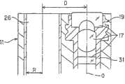
接着使用图2说明摄像单元19的结构。Next, the configuration of theimaging unit 19 will be described using FIG. 2 .

使用透镜框31和隔离件32a、32b来保持固定构成物镜系统17的多个透镜,以使得面间隔适当并且各透镜对中。CCD 18由CCD芯片18a、CCD基板18b、CCD驱动用部件18c和密封玻璃18d构成。Alens frame 31 and spacers 32a, 32b are used to hold fixed the plurality of lenses making up theobjective system 17 so that the facets are properly spaced and the lenses are centered. The CCD 18 is composed of a CCD chip 18a, a CCD substrate 18b, a CCD drive member 18c, and a sealing glass 18d.

CCD基板18b通过引线接合等与CCD芯片18a电连接,通过粘接剂等被机械固定。CCD基板18b上焊接着耦合电容器、电流放大用晶体管等CCD驱动用部件18c。CCD芯片18a的受光面上利用光学粘接剂等粘接固定有用于保护受光面的密封玻璃18d。The CCD substrate 18b is electrically connected to the CCD chip 18a by wire bonding or the like, and is mechanically fixed by an adhesive or the like. CCD driving components 18c such as coupling capacitors and current amplification transistors are soldered to the CCD substrate 18b. On the light receiving surface of the CCD chip 18a, a sealing glass 18d for protecting the light receiving surface is bonded and fixed with an optical adhesive or the like.

透镜框31与CCD框33嵌合,使得透镜框31可沿物镜系统17的光轴方向平行移动,CCD 18粘接固定在CCD框33上,使得上述物镜系统17的光轴与上述CCD 18的受光面垂直。Lens frame 31 is fitted withCCD frame 33, so thatlens frame 31 can move in parallel along the optical axis direction ofobjective lens system 17, and CCD 18 is bonded and fixed on theCCD frame 33, makes the optical axis of above-mentionedobjective lens system 17 and the above-mentioned CCD 18 The light-receiving surface is vertical.

CCD基板18b上设置有用于焊接信号电缆21的信号线的焊盘(未示出),信号电缆21的信号线被焊接。配置CCD保护框34,使其从CCD框33经过CCD 18,到达信号电缆21的与CCD基板18b的连接部,以进行机械保护。Pads (not shown) for soldering the signal lines of thesignal cable 21 are provided on the CCD substrate 18b, and the signal lines of thesignal cable 21 are soldered. The CCD protection frame 34 is configured so that it passes through the CCD 18 from theCCD frame 33 and reaches the connection portion of thesignal cable 21 with the CCD substrate 18b, so as to carry out mechanical protection.

该CCD保护框34中,在CCD芯片18a的背面部附近设置有切口部,以从该切口部插入的凡是配置有由导热性好的例如铝合金、铜合金等形成的散热部件35。该散热部件35上通过焊接、粘接剂等机械连接着以导热性好的金属为导体的散热用电缆36。In this CCD protection frame 34, a notch is provided near the back side of the CCD chip 18a, and a heat dissipation member 35 formed of aluminum alloy, copper alloy, etc. having good thermal conductivity is disposed through the notch. A heat dissipation cable 36 having a metal having good thermal conductivity as a conductor is mechanically connected to the heat dissipation member 35 by welding, adhesive, or the like.

CCD保护框34内部填充密封树脂,用具有热收缩性的管37密封CCD18周边。散热用电缆36焊接在热容量大的部件,如插入部7的前端部11上。信号电缆21是按如下形成的,将多个同轴线和多个单线合在一起,然后卷绕氟树脂制的带子,在其上缠绕铜线作为统一屏蔽,再在其上卷绕氟树脂制的带子,再在其上用特氟纶(テフロン)(注册商标)类护套覆盖。The inside of the CCD protection frame 34 is filled with sealing resin, and the periphery of the CCD 18 is sealed with a heat-shrinkable tube 37 . The heat dissipation cable 36 is welded to a component with a large heat capacity, such as thefront end portion 11 of theinsertion portion 7 . Thesignal cable 21 is formed by combining a plurality of coaxial wires and a plurality of single wires together, then winding a tape made of fluororesin, winding a copper wire on it as a unified shield, and winding a fluororesin thereon A belt made of a Teflon (Teflon) (registered trademark) type sheath is used to cover it.

如图3所示,插入部7的前端部11配置了:包含前端透镜的外径为φ2.8mm的物镜系统17的摄像单元19、通道前端开口26、去除在物镜系统17的外表面上因送水送气而造成的附着污物的送气送水喷嘴39、利用通过与光源装置3连接的光导14传送(导光)的光来照明被拍摄物体的照明透镜16a、16b。As shown in Figure 3, thefront end portion 11 of insertingpart 7 is configured: the outer diameter that comprises the front end lens is theimaging unit 19 of theobjective lens system 17 of φ 2.8mm, channelfront end opening 26, removes on the outer surface ofobjective lens system 17 because Air and water nozzles 39 for attaching dirt due to water and air, andillumination lenses 16 a and 16 b for illuminating the subject with light transmitted (guided) through thelight guide 14 connected to thelight source device 3 .

摄像单元19安装在前端部11上,被安装成当对被拍摄物体进行拍摄,在监视器5上显示时的监视器5上的上下方向与图3所示的插入部7的前端部11的上下方向一致。本实施例的通道管25a使用例如特氟纶(注册商标)制的内径2.8mm的管。Thecamera unit 19 is installed on thefront end portion 11, and is installed so that the vertical direction on themonitor 5 when the subject is photographed and displayed on themonitor 5 is the same as that of thefront end portion 11 of theinsertion portion 7 shown in FIG. 3 . Up and down in the same direction. For the channel tube 25a of this embodiment, for example, a tube with an inner diameter of 2.8 mm made of Teflon (registered trademark) is used.

如图4所示,物镜系统17的光轴O与(连接通道管25a的前端的)前端开口26平行配置,本实施例中,物镜系统17的中心(光轴O)与前端开口26的中心轴的距离D设定为6mm。该前端开口26的半径R的2倍与通道管25a的内径相同,是2.8mm。As shown in Figure 4, the optical axis O of theobjective lens system 17 is configured parallel to the front end opening 26 (connecting the front end of the channel pipe 25a). The distance D of the shaft is set to 6 mm. Twice the radius R of the front end opening 26 is 2.8 mm, which is the same as the inner diameter of the channel pipe 25 a.

如图1所示,光源装置3有灯40,利用由光圈驱动部41驱动的光圈42的开口调整了该灯40的照明光的透过光量后,该灯40的照明光通过会聚透镜43入射到光导连接器15上的光导14的入射端面上。并且,如上所述,从光导14的前端,再通过照明透镜16a、16b向被拍摄物体侧射出照明光。As shown in FIG. 1 , thelight source device 3 has alamp 40. After the aperture of theaperture 42 driven by theaperture drive unit 41 is used to adjust the transmitted light amount of the illumination light of thelamp 40, the illumination light of thelamp 40 is incident through a condensinglens 43. to the incident end face of thelight guide 14 on thelight guide connector 15 . And, as described above, from the front end of thelight guide 14, the illumination light is emitted toward the subject side through theillumination lenses 16a and 16b.

光导14在插入部7内分支为两条,如图3所示,从在前端部11配置在2个部位上的照明透镜16a、16b分别射出照明光。Thelight guide 14 is branched into two in theinsertion part 7, and as shown in FIG.

如图1所示,图像处理装置4中具有被输入来自CCD 18的图像信号的CDS电路44,由该CDS电路44提取出信号成分后,由A/D转换器45转换为数字信号。As shown in FIG. 1 , the image processing device 4 has aCDS circuit 44 to which an image signal from the CCD 18 is input, and after the signal component is extracted by theCDS circuit 44, it is converted into a digital signal by an A/D converter 45.

由该A/D转换器45转换的数字图像信号输入生成由亮度信号和颜色信号构成的视频信号的信号转换部46。通过该信号转换部46生成的视频信号输入进行γ校正等各种图像处理的图像处理部47。该图像处理部47的输出信号输入D/A转换器48,转换为模拟的与HDTV方式对应的视频信号后,输出到监视器5。The digital image signal converted by the A/D converter 45 is input to asignal conversion unit 46 that generates a video signal composed of a luminance signal and a color signal. The video signal generated by thesignal conversion unit 46 is input to animage processing unit 47 that performs various image processing such as gamma correction. The output signal of theimage processing unit 47 is input to the D/A converter 48 , converted into an analog video signal corresponding to the HDTV system, and output to themonitor 5 .

来自信号转换部46的亮度信号输入到生成调光信号的自动调光部49,通过该自动调光部49生成自动调光信号。该自动调光信号输入到光源装置3的光圈驱动部41,自动调整光圈42的开口量。The luminance signal from thesignal conversion unit 46 is input to an automatic dimming unit 49 that generates a dimming signal, and the automatic dimming unit 49 generates an automatic dimming signal. This automatic dimming signal is input to thediaphragm drive unit 41 of thelight source device 3 to automatically adjust the opening amount of thediaphragm 42 .

该自动调光部49内置有处理器具检测部49a,该处理器具检测部49a通过例如处理器具的反射光量和颜色,检测出处理器具进入到摄像单元19的视野内(换言之,在CCD 18的受光面上形成处理器具的图像)的情况。The automatic dimming unit 49 has a built-in treatment instrument detection unit 49a, and the treatment instrument detection unit 49a detects that the treatment instrument enters the field of view of theimaging unit 19 by, for example, the amount and color of the reflected light of the treatment instrument (in other words, in the light received by the CCD 18). The image of the treatment tool is formed on the surface).

该自动调光部49具有:从该处理器具检测部49a的输出信号检测出用于进行调光的亮度的亮度检测部49b;和根据来自该亮度检测部49b的输出信号生成自动调光信号的调光信号生成部49c。The automatic dimming unit 49 has: a brightness detection unit 49b that detects the brightness for dimming from the output signal of the treatment tool detection unit 49a; and a unit that generates an automatic dimming signal based on the output signal from the brightness detection unit 49b. The dimming signal generating unit 49c.

上述亮度检测部49b在处理器具检测部49a检测到处理器具的情况下,检测处理器具的像所成像的区域附近的峰值亮度(光量)和该区域附近的平均亮度(光量)。The luminance detection unit 49b detects the peak luminance (light intensity) near the area where the image of the treatment tool is formed and the average luminance (light intensity) around the area when the treatment tool detection unit 49a detects the treatment tool.

该亮度检测部49b在处理器具检测部49a未检测到处理器具的情况下,检测画面整体的峰值亮度和平均亮度。The luminance detection unit 49b detects the peak luminance and the average luminance of the entire screen when the treatment tool detection unit 49a has not detected the treatment tool.

调光信号生成部49c为了通过来自亮度检测部49b的峰值亮度和平均亮度的信号而得到适当亮度的信号,生成用于调整光源装置3的照明光量的自动调光信号,输出到光源装置3的光圈驱动部41。The dimming signal generation unit 49c generates an automatic dimming signal for adjusting the amount of illumination light of thelight source device 3 in order to obtain a signal of appropriate brightness from the signal of the peak brightness and the average brightness from the brightness detection unit 49b, and outputs it to the signal of thelight source device 3. Adiaphragm drive unit 41 .

本实施例的电子内窥镜2通过由上述透镜数据中所示的单焦点物镜系统17和CCD 18构成的摄像单元19,确保了(满足了条件)可识别间距为35μm的黑白色的分辨率,比现有技术的例子中的可识别50μm左右间距的黑白色的分辨率更高,同时确保了与现有技术的例子同样的观察远景侧所必需的分辨率。The electronic endoscope 2 of the present embodiment ensures (conditions are satisfied) that a black-and-white resolution with a pitch of 35 μm can be recognized by theimaging unit 19 composed of the single-focusobjective lens system 17 and the CCD 18 shown in the above-mentioned lens data. , which is higher than the black-and-white resolution at a pitch of about 50 μm in the conventional example, and at the same time ensures the resolution necessary for observing the distant view side as in the conventional example.

并且,摄像单元19的CCD 18输出对应于这种分辨率的图像信号,因此在对该图像信号进行生成标准视频信号的信号处理,显示在监视器5的显示面上的情况下,通过该显示图像,可识别35μm间距的黑白色。In addition, the CCD 18 of theimaging unit 19 outputs an image signal corresponding to such a resolution. Therefore, when the image signal is subjected to signal processing to generate a standard video signal and displayed on the display surface of themonitor 5, the display Image, black and white with 35μm pitch can be recognized.

观察远景侧必需的分辨率是在离开摄像单元19例如50mm左右的位置处可识别0.5mm间距的黑白色的分辨率,将该分辨率也叫作远景用分辨率。此外,可识别上述35μm间距的黑白色的分辨率也叫做接近侧精细分辨率。The resolution necessary for observing the distant view side is a resolution capable of recognizing black and white at a pitch of 0.5 mm at a position, for example, about 50 mm away from theimaging unit 19 , and this resolution is also called the resolution for the distant view. In addition, the resolution that can recognize the black and white of the above-mentioned 35 μm pitch is also called near-side fine resolution.

本实施例中,在插通到通道25内的处理器具28的前端侧从前端开口26突出的情况下,在物距为可得到能识别上述35μm间距的黑白色的分辨率的距离时,处理器具28的前端侧进入到摄像单元19的视野内。In this embodiment, when the front end side of thetreatment tool 28 inserted into thechannel 25 protrudes from thefront opening 26, when the object distance is a distance at which black and white resolution can be recognized at a pitch of 35 μm as described above, the treatment The front end side of theinstrument 28 enters the field of view of theimaging unit 19 .

并且,当在CCD 18的受光面上成像较小突出量的状态的处理器具28的前端侧的像,可详细观察处理器具28的前端附近的状态下,容易进行利用处理器具28的详细处理。In addition, when an image of the front end side of thetreatment tool 28 with a small protrusion is formed on the light receiving surface of the CCD 18, detailed treatment with thetreatment tool 28 can be easily performed in a state where the vicinity of the front end of thetreatment tool 28 can be observed in detail.

下面说明基于这种结构的本实施例的作用。The action of this embodiment based on this structure will be described below.

如图1所示,电子内窥镜2的光导连接器15连接于光源装置3上,信号连接器22连接于图像处理装置4上。该图像处理装置4的视频输出端上连接监视器5的电缆,设为可进行内窥镜检查的状态。As shown in FIG. 1 , theoptical connector 15 of the electronic endoscope 2 is connected to thelight source device 3 , and thesignal connector 22 is connected to the image processing device 4 . The cable of themonitor 5 is connected to the video output terminal of the image processing device 4 to be in a state where endoscopic examination can be performed.

并且,将未示出的电源开关接通,来自光源装置3的照明光提供给光导14,通过光导14将照明光从照明透镜16a、16b射出,设为可照明由摄像单元19拍摄的被拍摄物体的状态。通过摄像单元19的CCD 18拍摄的图像成为通过图像处理装置4显示在监视器5上的状态。In addition, the power switch not shown is turned on, the illumination light from thelight source device 3 is supplied to thelight guide 14, and the illumination light is emitted from theillumination lenses 16a, 16b through thelight guide 14, so that the subject photographed by theimaging unit 19 can be illuminated. the state of the object. The image captured by the CCD 18 of theimaging unit 19 is displayed on themonitor 5 by the image processing device 4.

接着将电子内窥镜2的插入部7插入患者体腔内,将插入部7的前端部11设成可观察体腔内的患部等作为要进行内窥镜检查的部位的被拍摄物体的状态。Next, theinsertion portion 7 of the electronic endoscope 2 is inserted into the body cavity of the patient, and thefront end portion 11 of theinsertion portion 7 is set so as to be able to observe an object to be photographed such as an affected part in the body cavity as a portion to be inspected by the endoscope.

此时,前端部11上设置的摄像单元19的物镜系统17在CCD 18的受光面上成像被拍摄物体的光学像。在CCD 18的受光面上成像的像被光电转换,转换为图像信号。该图像信号通过信号电缆21、信号连接器22输入图像处理装置4的CDS电路44。该图像信号的波形包含信号成分以外的复位噪声等,通过CDS电路44提取出信号成分,生成基带信号。At this time, theobjective lens system 17 of theimaging unit 19 provided on thefront end portion 11 forms an optical image of the object to be photographed on the light receiving surface of the CCD 18. The image formed on the light-receiving surface of the CCD 18 is photoelectrically converted into an image signal. The image signal is input to theCDS circuit 44 of the image processing device 4 through thesignal cable 21 and thesignal connector 22 . The waveform of this image signal includes reset noise and the like other than signal components, and theCDS circuit 44 extracts the signal components to generate a baseband signal.

该CDS电路44的输出信号输入A/D转换器45,A/D转换器45将作为模拟信号的图像信号转换为数字信号。转换为数字信号的图像信号由信号转换部46转换为视频信号。The output signal of thisCDS circuit 44 is input to the A/D converter 45, and the A/D converter 45 converts the image signal which is an analog signal into a digital signal. The image signal converted into a digital signal is converted into a video signal by thesignal conversion unit 46 .

此时,由于本实施例中采用补色系的马赛克滤色器作为CCD 18,因此该信号转换部46转换为从例如相邻的4种滤色器的像素信号输出取平均而得到的亮度信号、由各色的像素信号输出的差分得到的色差信号这样的视频信号。At this time, since the mosaic color filter of the complementary color system is adopted as the CCD 18 in the present embodiment, thesignal conversion section 46 is converted into a luminance signal obtained by averaging the pixel signal outputs of, for example, adjacent four kinds of color filters, A video signal such as a color-difference signal obtained by outputting a difference of pixel signals of each color.

该视频信号被图像处理部47进行适合于监视器显示的对比度调整、颜色调整和显示尺寸调整等。This video signal is subjected to contrast adjustment, color adjustment, display size adjustment, and the like suitable for monitor display by theimage processing unit 47 .

之后,由D/A转换器48转换为监视器5可显示的模拟的对应于HDTV方式的视频信号。监视器5在监视器画面5a上显示与输入的HDTV方式的视频信号对应的(由CCD 18拍摄的)被拍摄物体图像。Thereafter, it is converted by the D/A converter 48 into an analog video signal corresponding to the HDTV system that can be displayed on themonitor 5 . Themonitor 5 displays an object image (taken by the CCD 18) corresponding to the input video signal of the HDTV system on themonitor screen 5a.

接着参考图6说明通过摄像单元19对黑白对带子间距为35μm的被拍摄物体等拍摄时的作用。Next, the operation of theimaging unit 19 when imaging an object with a black-and-white pair-strip pitch of 35 μm will be described with reference to FIG. 6 .

图6表示将本实施例的电子内窥镜2的插入部7插入体腔内,由设置于前端部11上的摄像单元19对体腔内的处理对象部位侧进行拍摄,同时使处理器具28从前端开口26突出进行处理的情况下的概略图。6 shows that theinsertion portion 7 of the electronic endoscope 2 of this embodiment is inserted into the body cavity, and theimaging unit 19 arranged on thefront end portion 11 takes pictures of the treatment target site side in the body cavity. A schematic view of the case where theopening 26 protrudes for processing.

此时,作为容易进行处理的条件,希望对即使远景部分也能够以合适的分辨率进行拍摄(观察),并且对于作为处理对象的患部等可详细地观察,同时希望也能够详细观察从前端开口26突出的处理器具28的前端侧。At this time, as conditions for easy processing, it is desirable to be able to photograph (observe) with an appropriate resolution even for distant parts, and to be able to observe in detail the affected part as the processing target, and to be able to observe in detail from the front opening. 26 protrudes from the front end side of thetreatment tool 28 .

本实施例中,按如下所述来满足上述条件。首先为使说明更明确,按如下所述来定义亮度对比度G。In this embodiment, the above conditions are satisfied as follows. First, to clarify the description, the luminance contrast G is defined as follows.

在通过物镜系统17在CCD 18受光面上成像相同宽度的黑白带(条纹)的被拍摄物体时,将针对上述白色被拍摄物体的亮度的最大值设为Gmax、将上述黑色被拍摄物体的亮度的最小值设为Gmin、将亮度对比度G定义为G=(Gmax-Gmin)/(Gmax+Gmin)。When the subject of the black and white band (stripe) of the same width is imaged on the CCD 18 light-receiving surface by theobjective lens system 17, the maximum value of the brightness for the above-mentioned white subject is set as Gmax, and the brightness of the above-mentioned black subject is set to The minimum value of is set to Gmin, and the brightness contrast G is defined as G=(Gmax-Gmin)/(Gmax+Gmin).

这样定义亮度对比度G的情况下,当利用如上所述构成的摄像单元19得到最高分辨率的物距为4.2mm时,对黑白对带子的间距为35μm的被拍摄物体进行拍摄时,在CCD受光面上成像的白带和黑带的亮度对比度G为14.5%。When the brightness contrast G is defined in this way, when the object distance of the highest resolution is 4.2 mm obtained by using theimaging unit 19 constituted as described above, when the object to be photographed is photographed with a pitch of 35 μm between the black and white pairs of tapes, the CCD receives light The brightness contrast G of the white and black bands imaged on the surface is 14.5%.

通过上述物镜系统17在CCD 18的受光面上成像的间距为35μm的黑白对带子的被拍摄物体像中,从白带所成像的像素输出的图像信号与从黑带所成像的像素输出的图像信号之差为大致14.5%。In the object image of the black and white pairs of belts with a pitch of 35 μm formed on the light-receiving surface of the CCD 18 by the above-mentionedobjective lens system 17, the image signals output from the pixels imaged by the white belts and the image signals output by the pixels imaged from the black belts The difference is roughly 14.5%.

上述图像信号通过CDS电路44、A/D转换器45、信号转换部46输入图像处理部47,被实施例如适合于监视器5显示的γ处理和去除噪声的低通滤波处理等。The above-mentioned image signal is input to theimage processing unit 47 through theCDS circuit 44, A/D converter 45, andsignal conversion unit 46, and is subjected to, for example, gamma processing suitable for display on themonitor 5 and low-pass filter processing for removing noise.

并且,在将通过上述白色被拍摄物体得到的亮度信号的最大值设为Imax、通过上述黑色被拍摄物体得到的亮度信号的最小值设为Imin、对比度I定义为I=(Imax-Imin)/(Imax+Imin)的情况下,(对上述黑白对带子的间距为35μm的被拍摄物体进行拍摄时)以对比度I为10%以上的方式输出图像信号。由此,摄像单元19拍摄的35μm间距的黑白对带子在监视器5上可被识别为黑白对带子。And, when the maximum value of the luminance signal obtained by the above-mentioned white subject is set as Imax, the minimum value of the luminance signal obtained by the above-mentioned black subject is set as Imin, and the contrast I is defined as I=(Imax-Imin)/ In the case of (Imax+Imin), an image signal is output such that the contrast I is 10% or more (when the subject is photographed with a pitch of 35 μm between black and white pairs of tapes). As a result, the 35-μm-pitch black-and-white pair tape captured by theimaging unit 19 can be recognized as a black-and-white pair tape on themonitor 5 .

图6中,将得到最高分辨率的物距4.2mm设为d1、在该位置处配置了35μm间距的黑白对带子(条纹)Sa的情况下,由CCD 18进行光电转换,形成从例如信号转换部46输出的视频信号的亮度信号中的对比度I如上所述为10%以上,从而可在监视器5上识别35μm间距的黑白对带子。In Fig. 6, when the object distance 4.2mm for obtaining the highest resolution is set as d1, and a pair of black and white strips (stripes) Sa with a pitch of 35 μm are arranged at this position, photoelectric conversion is performed by the CCD 18 to form, for example, a signal conversion The contrast I in the luminance signal of the video signal output from theunit 46 is 10% or more as described above, so that the black and white pair bands at a pitch of 35 μm can be recognized on themonitor 5 .

在可在监视器5上识别上述35μm间距的黑白对带子的状态下,当在物距为50mm的位置处放置黑白对带子间距为0.5mm的被拍摄物体Sb,利用该摄像单元19进行拍摄时,CCD受光面上成像的白带和黑带的亮度对比度G为25%。When the above-mentioned pair of black and white tapes with a pitch of 35 μm can be recognized on themonitor 5, when an object Sb with a pitch of 0.5 mm between the pair of black and white tapes is placed at a position of 50 mm in object distance, and an image is taken by thisimaging unit 19 , The brightness contrast G of the white band and the black band imaged on the light receiving surface of the CCD is 25%.

同样在CCD 18的受光面上成像的间距为0.5mm的黑白对带子的被拍摄物体像被进行光电转换,从白带所成像的像素输出的图像信号与从黑带所成像的像素输出的图像信号之差为大致25%,通过图像处理装置4使白带和黑带的对比度I为10%以上,向监视器5输出。由此,由摄像单元19拍摄的配置在距离为50mm处的0.5mm间距的黑白对带子可在监视器5上被识别为黑白对带子。Also on the light-receiving surface of the CCD 18, the image of the black and white pair of tapes with a pitch of 0.5 mm is photoelectrically converted, and the image signal output from the pixel imaged by the white tape is output from the image signal output by the pixel imaged by the black tape. The difference is about 25%, and the contrast I of the white band and the black band is made to be 10% or more by the image processing device 4, and output to themonitor 5. Thereby, the black-and-white paired tapes arranged at a distance of 50 mm at a pitch of 0.5 mm captured by theimaging unit 19 can be recognized as black-and-white paired tapes on themonitor 5 .

图6中,表示在物距d2为50mm的位置上配置了间距为0.5mm的黑白对带子(条纹)Sb的情况,此时,信号转换部46的亮度信号中白与黑的对比度I为10%以上,在监视器5上可识别黑白对带子。In FIG. 6 , the situation where the black-and-white pair of strips (stripes) Sb with a pitch of 0.5 mm are arranged at a position where the object distance d2 is 50 mm is shown. % or more, the black and white pairs of tapes can be recognized on themonitor 5.

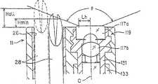
接着说明将处理器具插入通道25中进行处理的情况。操作者将使用的处理器具插入设置于操作部8附近的处理器具插入口27中。从处理器具插入口27插入的处理器具通过插入部7内的通道管25a的通道25内,被引导至插入部7的前端部11。当操作者将该处理器具28进一步插入深处侧时,处理器具28的前端从前端部11的通道前端开口26突出。要使突出的处理器具28被摄像单元19拍摄到所必需的条件为:如图5所示,由于在处理器具28移动到最靠近摄像单元19侧时,摄像单元19的前端透镜面处的光线高Lh=1.2mm、前端开口26的半径R=1.4mm、摄像单元19的视场角θ=138°、摄像单元19的光轴O与前端开口26的中心的距离D=6mm,因此按下式1所示导出处理器具28从插入部7的前端部11的前端面突出的最小突出量Hmin。Next, a case where a treatment instrument is inserted into thechannel 25 to perform treatment will be described. The operator inserts the treatment tool to be used into the treatmenttool insertion opening 27 provided near theoperation portion 8 . The treatment tool inserted from the treatmenttool insertion port 27 is guided to thefront end portion 11 of theinsertion unit 7 through thechannel 25 of the channel tube 25 a in theinsertion unit 7 . When the operator further inserts thetreatment tool 28 into the deep side, the front end of thetreatment tool 28 protrudes from the channel front end opening 26 of thefront end portion 11 . The necessary condition to make the protrudingtreatment tool 28 be photographed by thecamera unit 19 is: as shown in FIG. High Lh=1.2mm, radius R=1.4mm offront end opening 26, field angle θ=138° ofcamera unit 19, distance D=6mm between the optical axis O ofcamera unit 19 and the center offront end opening 26, so press The minimum protrusion amount Hmin of thetreatment tool 28 protruding from the front end surface of thefront end portion 11 of theinsertion portion 7 is derived as shown inEquation 1.

Hmin=(D-Lh-R)×tan(90°-θ/2)=1.38mm(式1)Hmin=(D-Lh-R)×tan(90°-θ/2)=1.38mm (Formula 1)

另一方面,在处理器具28位于离摄像单元19最远的方向上的情况下,处理器具28突出,要使处理器具28的前端整体被摄像单元19拍摄到所必需的条件为,作为处理器具28从插入部7的前端部11的前端面突出的突出量Hall,可按下式2导出。On the other hand, when thetreatment tool 28 is located in the direction farthest from theimaging unit 19, thetreatment tool 28 protrudes, and the condition necessary for the entire front end of thetreatment tool 28 to be captured by theimaging unit 19 is as follows: The protrusion amount Hall of 28 protruding from the front end surface of thefront end portion 11 of theinsertion portion 7 can be derived from Equation 2 below.

Hall=(D-Lh+R)×tan(90°-θ/2)=2.45mm(式2)Hall=(D-Lh+R)×tan(90°-θ/2)=2.45mm (Formula 2)

如式1、式2所示,处理器具28在从前端部11的前端面突出的突出量达到1.38mm以上时开始进入摄像单元19的视野内,突出2.45mm时处理器具28前端的几乎整体都进入视野内。As shown inEquation 1 and Equation 2, thetreatment tool 28 begins to enter the field of view of theimaging unit 19 when the amount of protrusion from the front end surface of thefront end portion 11 reaches 1.38 mm or more, and when the protrusion is 2.45 mm, almost the entire front end of thetreatment tool 28 disappears. Come into view.

通过以上所述,在为得到本实施例的摄像单元19的最高分辨率的物距4.2mm时,处理器具28的前端侧确实地进入摄像单元19的视野内,可在监视器4上进行识别。Through the above, when the object distance of 4.2 mm is the highest resolution for obtaining theimaging unit 19 of this embodiment, the front end side of thetreatment tool 28 will surely come into the field of view of theimaging unit 19 and can be recognized on the monitor 4. .

图6中,表示出处理器具28从通道的前端开口26突出的状态,处理器具28的前端进入摄像单元19的视野内后,通过再向前方突出,处理器具28的前端成为最大分辨率的物距状态。In FIG. 6 , the state in which thetreatment tool 28 protrudes from the front end opening 26 of the channel is shown. After the front end of thetreatment tool 28 enters the field of view of theimaging unit 19, and then protrudes forward, the front end of thetreatment tool 28 becomes the object with the maximum resolution. distance status.

因此,可更详细观察由处理器具28进行处理的患部等被拍摄物体,同时也可非常细致地观察其附近突出的处理器具28的前端的状态,容易进行处理。该状态下,可对远景侧确保远景用分辨率,因此可把握要进行处理的部位周围的宽范围的状态,可更顺利地进行处理。Therefore, it is possible to observe in more detail an object such as an affected part treated by thetreatment tool 28, and also to observe very finely the state of the tip of thetreatment tool 28 protruding from its vicinity, thereby facilitating treatment. In this state, the resolution for the distant view can be ensured for the distant view side, so the state of a wide range around the part to be processed can be grasped, and the processing can be performed more smoothly.

接着说明本实施例的自动调光功能。Next, the automatic dimming function of this embodiment will be described.

自动调光部49在处理器具28未进入摄像单元19的视野内的情况下,由亮度检测部49b检测出画面整体的亮度(具体说是峰值亮度或平均亮度),输出给调光信号产生部49c。该调光信号产生部49c在画面暗时向光源装置3输出控制信号,具体说是自动调光信号,以增大发光。在画面过于明亮的情况下,输出作为控制光源装置3以减小发光的控制信号的自动调光信号。When thetreatment instrument 28 does not enter the field of view of theimaging unit 19, the automatic dimming unit 49 detects the brightness of the entire screen (specifically, peak brightness or average brightness) by the brightness detection unit 49b, and outputs it to the dimming signal generation unit. 49c. The dimming signal generator 49c outputs a control signal, specifically an automatic dimming signal, to thelight source device 3 to increase light emission when the screen is dark. When the screen is too bright, an automatic dimming signal is output as a control signal for controlling thelight source device 3 to reduce light emission.

通过该自动调光信号,光源装置3内的光圈驱动部41驱动光圈42,调整从灯40通过光圈42入射到光导14的入射端的照明光量。接着说明为了通过利用摄像单元19的内窥镜观察,对患部等被拍摄物体进行治疗用的组织采集和病变部切除,而使用处理器具28的情况下的自动调光的作用。Theaperture driving unit 41 in thelight source device 3 drives theaperture 42 based on the automatic dimming signal, and adjusts the amount of illumination light entering the incident end of thelight guide 14 from thelamp 40 through theaperture 42 . Next, the function of the automatic light adjustment in the case of using thetreatment tool 28 for tissue harvesting for treatment and lesion excision of an object to be photographed such as an affected part through endoscopic observation by theimaging unit 19 will be described.

通过将处理器具28插入通道25,使处理器具28经过插入部7的前端部11的前端开口26,从其前端面突出,从而使处理器具进入摄像单元19的视野内。By inserting thetreatment tool 28 into thechannel 25 , thetreatment tool 28 passes through thefront opening 26 of thefront end portion 11 of theinsertion part 7 and protrudes from the front end thereof, so that thetreatment tool 28 enters the field of view of theimaging unit 19 .

此时,例如根据处理器具28的颜色、处理器具28的反射光等,处理器具检测部49a检测出处理器具28进入了视野内,检测出基于以上述处理器具28为中心的一定区域的峰值亮度和平均亮度的亮度。调光信号产生部49c输出作为控制信号的自动调光信号,以便当上述处理器具28附近的亮度过亮时使光源装置3减小发光,过暗时使光源装置3增大发光。At this time, for example, based on the color of thetreatment tool 28, reflected light from thetreatment tool 28, etc., the treatment tool detection unit 49a detects that thetreatment tool 28 has entered the field of view, and detects the peak luminance based on a certain area centered on thetreatment tool 28. and the brightness of the average brightness. The dimming signal generator 49c outputs an automatic dimming signal as a control signal to reduce the light emission of thelight source device 3 when the brightness near thetreatment tool 28 is too bright, and to increase the light emission of thelight source device 3 when it is too dark.

并且,通过自动调光信号,光源装置3内的光圈驱动部41驱动光圈42,调整从灯40通过光圈42入射到光导14的后端的照明光量。通过该自动调光信号,可进行自动调光,使得处理器具28进入摄像单元19的视野内的区域附近的亮度为适合于观察的亮度。Then, theaperture drive unit 41 in thelight source device 3 drives theaperture 42 by the automatic dimming signal, and adjusts the amount of illumination light incident from thelamp 40 to the rear end of thelight guide 14 through theaperture 42 . With this automatic dimming signal, automatic dimming can be performed so that the brightness around the region where thetreatment tool 28 enters the field of view of theimaging unit 19 becomes a brightness suitable for observation.

作为照明光量的调整方法,除了光圈驱动部42的光圈控制外,还可设置控制提供给光源的功率(电流值、电压值等)的控制部,通过调整该功率进行照明光量的调整。此外,也可以在插入部7的前端设置作为光源的发光二极管(LED),根据亮度检测部49b的检测结果调整对发光二极管的供给电流,而进行发光亮(照明光量)的调整。As a method of adjusting the amount of illumination light, in addition to the aperture control of theaperture drive section 42, a control section that controls power (current value, voltage value, etc.) supplied to the light source may be provided, and the amount of illumination light may be adjusted by adjusting the power. In addition, a light emitting diode (LED) as a light source may be provided at the tip of theinsertion portion 7, and the light emission (illumination light amount) may be adjusted by adjusting the supply current to the LED according to the detection result of the brightness detection unit 49b.

接着说明摄像单元19中配置的散热部件35、以及散热用电缆36的作用。Next, the functions of the heat dissipation member 35 and the heat dissipation cable 36 arranged in theimaging unit 19 will be described.

当驱动CCD 18时,CCD芯片18a、电流放大器等CCD驱动用部件18c发热。一般地,像素数越多,驱动频率越高,消耗功率也增大,CCD芯片18a发热。散热部件35与CCD芯片18a和CCD基板18b相邻配置,因此CCD 18的热传导到散热部件35,之后传导到散热用电缆36。此外,向连接散热用电缆36的插入部7的前端部件传递热,CCD 18产生的热被散发,可防止CCD芯片18a的高度发热。When the CCD 18 is driven, the CCD driving components 18c such as the CCD chip 18a and the current amplifier generate heat. Generally, as the number of pixels increases, the drive frequency increases, power consumption increases, and the CCD chip 18a generates heat. The heat dissipation member 35 is disposed adjacent to the CCD chip 18a and the CCD substrate 18b, so the heat of the CCD 18 is conducted to the heat dissipation member 35, and then to the heat dissipation cable 36. In addition, the heat is transferred to the front end part of theinsertion part 7 connected to the heat radiation cable 36, and the heat generated by the CCD 18 is dissipated, so that the CCD chip 18a can be prevented from being highly heated.

由于信号电缆21在统一屏蔽与护套之间卷绕有带子,所以例如在向信号电缆21施加了扭转的机械应力时,由于护套的扭转与统一屏蔽的扭转不同造成的统一屏蔽与护套之间的摩擦、护套对统一屏蔽施加的牵引力被统一屏蔽与护套之间的带子缓解,因此具有耐扭转性增加的效果。Since thesignal cable 21 is wound with a tape between the unified shield and the sheath, for example, when a torsional mechanical stress is applied to thesignal cable 21, the unified shield and the sheath due to the twist of the sheath and the twist of the unified shield are different. The friction between them, the traction exerted by the jacket on the uniform shield, is relieved by the strap between the uniform shield and the jacket, thus having the effect of increased resistance to torsion.

本实施例具有如下效果。This embodiment has the following effects.

本实施例中,构成摄像单元19的物镜光学系统采用单焦点光学系统,因此与倍率变更光学系统和可变焦光学系统相比结构简单。In this embodiment, the objective optical system constituting theimaging unit 19 adopts a single-focus optical system, and thus has a simpler structure than a magnification changing optical system and a zoom optical system.

以往的电子内窥镜使用的采用了单焦点光学系统的摄像单元的分辨率为可识别50μm左右的黑白对带子的被拍摄物体的水平,与此相比,如上所述,根据本实施例的摄像单元19,可识别更高分辨率的35μm的黑白对带子的被拍摄物体。Compared with the resolution of the imaging unit using the single-focus optical system used in conventional electronic endoscopes, which is at the level of recognizing a black-and-white paired object of about 50 μm, as described above, according to the present embodiment Thecamera unit 19 can recognize the object to be photographed in a 35 μm black-and-white pair tape with a higher resolution.

当为上述摄像单元19可得到上述最高分辨率的距离时,由于从通道25的前端开口26突出的处理器具28的前端侧可在监视器5上被识别,能够一边进行用以往的使用变焦光学系统的内窥镜很难进行的详细观察,一边进行处理作业。例如,可得到如下效果:一边进行大肠的凹坑图案这样的被拍摄物体的详细观察,一边利用处理器具28进行处理。When the distance at which the above-mentioned highest resolution can be obtained by the above-mentionedimaging unit 19, since the front end side of thetreatment tool 28 protruding from the front end opening 26 of thechannel 25 can be recognized on themonitor 5, it is possible to perform the same process while using the conventional zoom optics. The endoscope of the system performs processing while observing detailed observations that are difficult to perform. For example, it is possible to obtain an effect of performing treatment with thetreatment tool 28 while performing detailed observation of a subject such as a pit pattern of the large intestine.

由于得到最高分辨率的距离为4.2mm左右,所以本实施例中当为与该距离相比为跟前侧的物距时,处理器具28的前端侧能够进入视野内,可通过进一步向前方侧突出而变成得到最高分辨率的距离的状态。因此,本实施例中,在为得到最高分辨率的距离时,处理器具28的前端侧可充分进入视野内,达到处理器具28的操作比较容易的效果。Since the distance at which the highest resolution is obtained is about 4.2mm, in this embodiment, when the object distance is on the front side compared with this distance, the front end side of thetreatment tool 28 can enter the field of view, and can be further protruded forward. Instead, the distance of the highest resolution is obtained. Therefore, in this embodiment, at the distance to obtain the highest resolution, the front end side of thetreatment tool 28 can fully enter the field of view, so that the operation of thetreatment tool 28 is relatively easy.

此外,在物距为50mm时,由于可在监视器5上识别与以往的内窥镜同样的黑白对带子为0.5mm的被拍摄物体,因此不需要繁杂的操作就可进行从远景到近景的观察。In addition, when the object distance is 50 mm, since the same black-and-white object with a tape length of 0.5 mm as conventional endoscopes can be recognized on themonitor 5, it is possible to perform a long-range view to a close-up view without complicated operations. observe.

此外,当插入处理器具28,变成将其前端显示在监视器5上的状态时,由于控制光源装置3的照明光量使得处理器具28附近的亮度为最佳,因此容易进行处理。In addition, when thetreatment tool 28 is inserted and its front end is displayed on themonitor 5, since the illumination light quantity of thelight source device 3 is controlled so that the brightness near thetreatment tool 28 is optimized, the treatment is easy.

这里,本实施例中,设CCD 18的像素间距为2.5μm、有效像素数为81万像素、摄像单元19的最大视场角为138°、得到最高分辨率的距离为4.2mm、摄像单元19的光轴O与前端开口26中心的距离为6mm,但不限定于此。Here, in the present embodiment, suppose that the pixel pitch of CCD 18 is 2.5 μ m, the number of effective pixels is 810,000 pixels, the maximum field of view ofcamera unit 19 is 138 °, and the distance to obtain the highest resolution is 4.2mm, andcamera unit 19 The distance between the optical axis O and the center of thefront opening 26 is 6mm, but it is not limited thereto.

例如,对黑白对带子的间距为35μm的被拍摄物体进行拍摄时,变更像素间距、有效像素数、最大视场角等,使得从拍摄上述白色被拍摄物体获得的像素得到的输出信号与从拍摄上述黑色被拍摄物体获得的像素得到的输出信号之差为10%以上,并且在拍摄上述35μm的被拍摄物体时输出信号之差为10%以上的物距时,即使变更最大视场角、及摄像单元19的光轴O与前端开口26中心的距离,使得能够观察处理器具,也可得到大致相同的效果。For example, when photographing a subject with a pitch of 35 μm between black-and-white pairs of bands, change the pixel pitch, effective number of pixels, maximum field of view, etc., so that the output signal obtained from the pixels obtained from photographing the above-mentioned white subject is the same as that obtained from the photographing When the difference between the output signals obtained by the pixels obtained by the above-mentioned black subject is 10% or more, and when the above-mentioned 35 μm subject is photographed, the difference between the output signals is 10% or more at the object distance, even if the maximum viewing angle is changed, and The distance between the optical axis O of theimaging unit 19 and the center of thefront opening 26 is such that the treatment instrument can be observed, and substantially the same effect can be obtained.

上述说明中,CCD 18的有效像素数为81万像素,但在马赛克滤色器方式的情况下,即便是85万像素左右也可实现同样的效果,此时,具有可进一步增大获得最高分辨率的距离的效果。In the above description, the effective number of pixels of CCD 18 is 810,000 pixels, but in the case of the mosaic color filter method, the same effect can be achieved even with about 850,000 pixels. The effect of the distance of the rate.

另一方面,在比85万像素更大的像素的情况下,不能得到实用的景深,若要得到最高分辨率则远点的深度变得不足,若确保远点的深度,则最高分辨率变为黑白对带子的间距为40μm以上。On the other hand, in the case of pixels larger than 850,000 pixels, a practical depth of field cannot be obtained, and the depth of the far point becomes insufficient to obtain the highest resolution. If the depth of the far point is ensured, the highest resolution becomes The pitch between black and white pairs of tapes is 40 μm or more.

本实施例中,使用补色系的马赛克滤色器方式的彩色CCD进行了说明,但不限定于此,电子内窥镜中,有时还使用如下方式:使用切换式等的三原色光作为照明光,与按顺序照射的三原色光同步,由单色(黑白)CCD取入被拍摄物体像,在图像处理装置中进行彩色化,即使是这种方式,通过满足上述条件也可得到同样效果。In this embodiment, a color CCD of the mosaic color filter method of the complementary color system is used for explanation, but it is not limited to this. In electronic endoscopes, a system may be used in which three primary color lights such as a switching type are used as illumination light, Even in this way, the same effect can be obtained by satisfying the above conditions even if the subject image is captured by a monochrome (black and white) CCD in synchronization with the three primary colors of light irradiated sequentially, and is colored by an image processing device.

该方式的情况下,能够得到R信号、G信号、B信号,作为有效像素数为35万像素左右的CCD输出信号,不生成亮度信号也可向监视器5输出,该情况下只要将亮度最高的G信号作为亮度信号即可。In the case of this method, R signal, G signal, and B signal can be obtained as CCD output signals with an effective pixel number of about 350,000 pixels, and can be output to themonitor 5 without generating a brightness signal. The G signal can be used as the brightness signal.

视场角优选是考虑了周围的观察性的一般的内窥镜中使用的是100°以上的视场角,视场角更宽的话,则具有处理器具检测距离变短的效果。The angle of view is preferably 100° or more, which is used in general endoscopes in consideration of the observation of the surroundings. If the angle of view is wider, the detection distance of the treatment tool will be shortened.

本实施例的图像处理装置4和监视器5利用对应于HDTV方式的视频信号来进行说明,但不限定于此,例如也可使用对应于SVGA、XGA这样的高分辨率监视器的显示方式。The image processing device 4 and monitor 5 of the present embodiment are described using video signals corresponding to the HDTV system, but are not limited thereto. For example, a display system corresponding to a high-resolution monitor such as SVGA or XGA may be used.

此外,本实施例的摄像单元19中,作为释放CCD 18的热的部件,公开了通过散热部件35和散热用电缆36向插入部7的前端部件散热,但也可以是如下结构:不在散热部件35上设置散热用电缆36,使插入部7的前端部件的导热性好的部分接近与散热部件对置的部分,通过导电性好的密封树脂等散热。In addition, in theimaging unit 19 of the present embodiment, as the parts for releasing the heat of the CCD 18, it is disclosed to dissipate heat to the front end part of theinsertion part 7 through the heat dissipation component 35 and the heat dissipation cable 36, but it may also be the following structure: 35 is provided with a heat dissipation cable 36, so that the portion with good thermal conductivity of the front end part of theinsertion portion 7 is close to the portion opposite to the heat dissipation component, and the heat is dissipated through a conductive sealing resin or the like.

作为散热用电缆36,也可使用信号电缆21的一部分。例如信号电缆21内也可设置不用于驱动的虚设电缆(dummy cable),还可使用以信号电缆21的电磁屏蔽为目的的外部屏蔽。并且,不设置散热部件35,在CCD芯片18a附近用导热性好的密封树脂来固定散热用电缆36的导体部分,也可得到同样的散热效果。A part of thesignal cable 21 may also be used as the heat dissipation cable 36 . For example, a dummy cable not used for driving may be provided inside thesignal cable 21, and an external shield for the purpose of electromagnetic shielding of thesignal cable 21 may be used. Furthermore, the same heat dissipation effect can be obtained by fixing the conductor portion of the heat dissipation cable 36 near the CCD chip 18a with sealing resin having good thermal conductivity without providing the heat dissipation member 35 .

在CCD基板18b上配置CCD芯片18a内部的输出级作为外部放大器,将CCD芯片18a的消耗功率分配给外部基板上的部件,由此来抑制CCD芯片18a的发热也是有效的。It is also effective to dispose the output stage inside the CCD chip 18a as an external amplifier on the CCD substrate 18b and distribute the power consumption of the CCD chip 18a to components on the external substrate, thereby suppressing heat generation of the CCD chip 18a.

(实施例2)(Example 2)

接着参考图7到图10说明本发明实施例2。本实施例基本结构与实施例1相同,而CCD的有效像素数和物镜系统、摄像单元和处理器具通道的位置关系不同。下面以不同之处为重点来说明。Next, Embodiment 2 of the present invention will be described with reference to FIG. 7 to FIG. 10 . The basic structure of this embodiment is the same as that ofEmbodiment 1, but the number of effective pixels of the CCD and the positional relationship between the objective lens system, the camera unit and the channel of the processing tool are different. The differences are highlighted below.

本实施例的结构如下。The structure of this embodiment is as follows.

本实施例的电子内窥镜的前端部11中采用了图7或图8所示的具有物镜系统72和CCD 73的摄像单元19B。The imaging unit 19B having theobjective lens system 72 and the CCD 73 shown in FIG. 7 or 8 is used in thefront end portion 11 of the electronic endoscope of this embodiment.

该CCD 73采用像素间距为3.3μm、对于监视器显示有效的像素数是40万像素、CCD受光面上的最大像高为约1.29mm的CCD。The CCD 73 employs a CCD with a pixel pitch of 3.3 μm, an effective pixel count of 400,000 pixels for monitor display, and a maximum image height of about 1.29 mm on the CCD light-receiving surface.

摄像单元19B被设定成,最大视场角为160°的单焦点物镜系统72的最前面配置形成为凹凸形状的透镜,Fno为9.18,以便不超过光的衍射界限。调整焦点以使得在物距为2.95mm时得到最高分辨率。The imaging unit 19B is set so that the front of the single-focusobjective lens system 72 with a maximum viewing angle of 160° is arranged as a concave-convex lens, and the Fno is 9.18 so as not to exceed the diffraction limit of light. Focus was adjusted so that the highest resolution was obtained at an object distance of 2.95 mm.

本实施例中使用的物镜系统72的透镜数据如下所示。The lens data of theobjective lens system 72 used in this embodiment are shown below.

F1=1.13723mmF1=1.13723mm

面No.    Ra         Da        Ne           VdNoodle No. Ra Da Ne Ne Vd

1        8.200      0.35      1.88815      40.81 8.200 0.35 1.88815 40.8

2        0.910      0.662 0.910 0.66

3        ∞         0.40      1.52498      59.93 ∞ 0.40 1.52498 59.9

4        ∞         0.284 ∞ 0.28

5        6.994      1.91      1.77621      49.65 6.994 1.91 1.77621 49.6

6        -2.210     0.036 -2.210 0.03

7        ∞(光圈)   0.037 ∞(aperture) 0.03

8        ∞         0.60      1.51965      75.08 ∞ 0.60 1.51965 75.0

9        ∞         1.019 ∞ 1.01

10        3.288      1.35      1.73234      54.710 3.288 1.35 1.73234 54.7

11        -1.630     0.35      1.93429      18.911 -1.630 0.35 1.93429 18.9

12        -5.110     0.5312 -5.110 0.53

13        ∞         0.0313 ∞ 0.03

14        ∞         1.00      1.51825      64.114 ∞ 1.00 1.51825 64.1

15        ∞         0.01      1.51193      63.015 ∞ 0.01 1.51193 63.0

16        ∞         1.00      1.61379      50.216 ∞ 1.00 1.61379 50.2

17        ∞         0.0017 ∞ 0.00

如图7所示,插入部的前端部11配置有:包含前端透镜的外径为φ2.8mm、形状为凹凸形状的物镜系统72的摄像单元19B;通道前端开口26B;去除在物镜系统72的前端表面上因送气送水而造成的附着污物的送气送水喷嘴39;利用通过与光源装置4连接的未图示的光导的光来照明被拍摄物体的照明透镜16a、16b。As shown in Figure 7, thefront end portion 11 of inserting part is equipped with: the outer diameter that comprises the front end lens is the imaging unit 19B of theobjective lens system 72 of φ 2.8mm, shape is concavo-convex shape; Passage front end opening 26B; Air and water nozzles 39 for attaching dirt due to air and water on the front end surface;Illumination lenses 16a and 16b for illuminating the subject with light passing through an unillustrated light guide connected to the light source device 4 .

摄像单元19B在插入部前端上被安装成使得在对被拍摄物体进行拍摄并显示在监视器5上时的监视器5上的上下方向与图7所示的插入部前端的上下方向一致。The imaging unit 19B is attached to the front end of the insertion part such that the vertical direction on themonitor 5 when the subject is photographed and displayed on themonitor 5 coincides with the vertical direction of the front end of the insertion part shown in FIG. 7 .

内径为φ2.8mm的处理器具通道25被配置在相对于摄像单元19B稍稍偏离水平方向的左斜下方的方向上,如图7所示,设前端部11的上下方向为Y轴、左右方向为X轴时,连接处理器具通道25的中心轴与摄像单元19B的光轴O的直线相对于上述X轴成α的角度。Thetreatment instrument channel 25 with an inner diameter of φ2.8 mm is arranged in a direction obliquely downward to the left slightly deviated from the horizontal direction with respect to the imaging unit 19B, as shown in FIG. In the case of the X-axis, the straight line connecting the central axis of thetreatment tool channel 25 and the optical axis O of the imaging unit 19B forms an angle α with respect to the X-axis.

如图8所示,物镜系统72的光轴O与前端开口26B平行配置,本实施例中,物镜系统72的中心(光轴O)与前端开口26B的中心轴的距离D设定为6mm。As shown in FIG. 8 , the optical axis O of theobjective lens system 72 is arranged parallel to the front opening 26B. In this embodiment, the distance D between the center (optical axis O) of theobjective lens system 72 and the central axis of the front opening 26B is set to 6 mm.

下面说明本实施例的作用。The action of this embodiment will be described below.

首先,说明由摄像单元19B拍摄黑白对带子间距为35μm的被拍摄物体时的作用。First, the operation when the imaging unit 19B captures a subject with a black-and-white pair-strip pitch of 35 μm will be described.

如上所述构成的摄像单元19B中,在物距为得到最高分辨率的物距2.95mm时,对黑白对带子间距为35μm的被拍摄物体进行拍摄时,CCD受光面上成像的白带和黑带的对比度G为11.5%。In the imaging unit 19B constituted as above, when the object distance is 2.95 mm, which is the object distance for obtaining the highest resolution, and the object to be photographed is photographed with a black-and-white pair of tape spacing of 35 μm, the white and black bands imaged on the CCD light-receiving surface The contrast ratio G is 11.5%.

通过上述物镜系统72在CCD 73的受光面上成像的间距为35μm的黑白对带子的被拍摄物体像被光电转换。并且,从白带所成像的像素输出的图像信号与从黑带所成像的像素输出的图像信号之差为大致11.5%。The black-and-white pairs of strips with a pitch of 35 μm formed on the light-receiving surface of the CCD 73 by the above-mentionedobjective lens system 72 are photoelectrically converted. And, the difference between the image signal output from the pixel imaged by the white band and the image signal output by the pixel imaged by the black band is about 11.5%.

该图像信号通过CDS电路44、A/D转换器45、信号转换部46输入图像处理部47,例如被实施适合于监视器的γ(ガンマ)处理和电掩码(mask)处理等,使白带与黑带的对比度I达到10%以上,输出到监视器5。The image signal is input to theimage processing section 47 through theCDS circuit 44, the A/D converter 45, and thesignal conversion section 46, and is subjected to, for example, gamma (Ganma) processing and electric mask (mask) processing suitable for a monitor, so that the leucorrhea The contrast I with the black band is 10% or more, and the output is output to themonitor 5 .

由此,由摄像单元19B拍摄的35μm间距的黑白对带子在监视器上可被识别为黑白对带子。Thereby, the black-and-white pair tape with a pitch of 35 μm captured by the imaging unit 19B can be recognized as a black-and-white pair tape on the monitor.

当在物距为50mm的位置处放置黑白对带子间距为0.5mm的被拍摄物体,由本实施例的摄像单元19B进行拍摄的情况下,在CCD 73受光面上成像的白带和黑带的对比度G为19.3%。When the object distance is placed at the position of 50mm, the object to be photographed is 0.5mm in black and white pair of strips, and the camera unit 19B of the present embodiment is used for shooting, the contrast G of the white band and the black band on the CCD 73 light-receiving surface. was 19.3%.

同样在CCD 73的受光面上成像的间距为0.5mm的黑白对带子的被拍摄物体被光电转换,从白带所成像的像素输出的图像信号与从黑带所成像的像素输出的图像信号之差为大致19.3%,通过图像处理装置4使白带和黑带的对比度I达到10%以上,输出给监视器5。Also on the light-receiving surface of the CCD 73, the black-and-white pair of strips with a pitch of 0.5 mm is photoelectrically converted, and the difference between the image signal output from the pixel imaged by the white strip and the image signal output by the pixel imaged by the black strip is It is approximately 19.3%, and the contrast I of the white band and the black band is made to be 10% or more by the image processing device 4 and output to themonitor 5 .

由此,由摄像单元19B拍摄的配置在距离为50mm处的0.5mm间距的黑白对带子可在监视器5上被识别为黑白带。Thereby, the pair of black and white tapes arranged at a distance of 50 mm at a pitch of 0.5 mm captured by the imaging unit 19B can be recognized as black and white tapes on themonitor 5 .

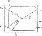
上述电掩码处理是如图9所示,在监视器5的显示画面内作成高宽比为1∶1.2的八角形的显示区域5b,在该八角形的显示区域5b中显示摄像单元19B拍摄的被拍摄物体。Above-mentioned electrical masking process is as shown in Figure 9, makes theoctagonal display area 5b that aspect ratio is 1:1.2 in the display screen ofmonitor 5, and in thisoctagonal display area 5b, shows photographing unit 19B shot of the object to be photographed.

在通过上述电掩码处理得到的显示区域5b上的视场角如是图9所示的横向方向长的显示区域的情况下,对角方向的P点为最大的视场角(θmax)。实施掩码处理使得物镜系统72的视场角160°与上述最大视场角θmax一致。另一方面,通过掩码处理,使得监视器画面上视场角最窄的是上下方向,其次窄的是左右方向的视场角。When the viewing angle on thedisplay region 5b obtained by the electric masking process is a display region long in the lateral direction as shown in FIG. 9 , the point P in the diagonal direction is the maximum viewing angle (θmax). Mask processing is performed so that the angle of view of theobjective lens system 72 of 160° coincides with the above-mentioned maximum angle of view θmax. On the other hand, through the masking process, the narrowest field of view on the monitor screen is the up-down direction, and the next narrowest field of view is the left-right direction.

作为上述最大对角的P点被设定成使连接P点和画面中心的直线与监视器画面上的水平方向所成角度为α,此外,摄像单元19B如图7所示,被配置成使插入部的前端部11的X轴方向与监视器水平方向一致,因此从配置在相对于X轴成α角度的位置处的处理器具通道25的前端开口26B突出的处理器具28如图9所示,从监视器5上的大概而言为水平方向,更严格地说是比水平方向稍稍下侧的左下方的P点附近开始,显示在显示区域5b内。The P point as the above-mentioned maximum diagonal is set so that the angle formed by the straight line connecting the P point and the center of the screen and the horizontal direction on the monitor screen is α. In addition, the imaging unit 19B is arranged such that, as shown in FIG. The X-axis direction of thefront end portion 11 of the insertion portion coincides with the horizontal direction of the monitor, so thetreatment tool 28 protruding from the front end opening 26B of thetreatment tool channel 25 disposed at an angle α with respect to the X-axis is shown in FIG. 9 , is displayed in thedisplay area 5b from the vicinity of point P on the lower left in a roughly horizontal direction on themonitor 5, and more strictly speaking, slightly lower than the horizontal direction.

要使本实施例中的从插入部的前端部11的前端开口26B突出的处理器具28被摄像单元19B拍摄到的必要条件为:当处理器具28移动到最靠摄像单元19B侧时,由于摄像单元19B的前端透镜面处的光线高为Lh=1.31mm、前端开口26B的半径R=2.8mm、摄像单元19B的视场角θ=160°、摄像单元19B的光轴O与通道25的距离D=6mm,因此作为处理器具28从前端部11的前端面突出的最小突出量为Hmin,可按式3导出。The necessary condition for making thetreatment tool 28 protruding from the front end opening 26B of thefront end portion 11 of the insertion part in this embodiment to be photographed by the imaging unit 19B is: when thetreatment tool 28 moves to the side closest to the imaging unit 19B, due to the The height of light at the front lens surface of unit 19B is Lh=1.31mm, the radius R=2.8mm of the front opening 26B, the field angle θ=160° of the camera unit 19B, the distance between the optical axis O of the camera unit 19B and the channel 25 D=6mm, therefore, the minimum amount of protrusion of thetreatment tool 28 from the front end surface of thefront end portion 11 is Hmin, which can be derived according toEquation 3.

Hmin=(D-Lh-R)×tan(90°-θ/2)=0.58mm(式3)Hmin=(D-Lh-R)×tan(90°-θ/2)=0.58mm (Formula 3)

另一方面,在处理器具28位于离开摄像单元19B最远的方向上的情况下,处理器具28突出,要使处理器具28的前端整体被摄像单元19B拍摄到的必要条件为:作为处理器具28从前端部11的前端面突出的突出量Hall,按下式4所示导出。On the other hand, when thetreatment tool 28 is located in the farthest direction from the imaging unit 19B, thetreatment tool 28 protrudes, and the necessary condition for the entire front end of thetreatment tool 28 to be photographed by the imaging unit 19B is: as thetreatment tool 28 The protrusion amount Hall protruding from the front end surface of thefront end portion 11 is derived as shown in Equation 4 below.

Hall=(D-Lh+R)×tan(90°-θ/2)=1.07mm(式4)Hall=(D-Lh+R)×tan(90°-θ/2)=1.07mm (Formula 4)

如式3、式4所示,当处理器具28从前端部11的前端面突出的突出量达到0.58mm以上时开始进入摄像单元19B的视野内,突出量大于1.07mm时处理器具28的前端的大致整体都进入视野内。As shown inEquation 3 and Equation 4, when the protrusion amount of thetreatment tool 28 from the front end surface of thefront end portion 11 reaches more than 0.58 mm, it begins to enter the field of view of the imaging unit 19B, and when the protrusion amount is greater than 1.07 mm, the front end of thetreatment tool 28 Almost all of them come into view.

由此,在距离为可获得本实施例的摄像单元19B的最高分辨率的2.95mm时,处理器具28的前端侧进入摄像单元19B的视野内,可在监视器5上被识别。As a result, at a distance of 2.95 mm at which the highest resolution of the imaging unit 19B of this embodiment can be obtained, the distal end side of thetreatment instrument 28 enters the field of view of the imaging unit 19B and can be recognized on themonitor 5 .

本实施例具有如下效果。This embodiment has the following effects.

本实施例中,构成摄像单元19B的物镜光学系统采用单焦点光学系统,因此与倍率变更光学系统和可变焦点光学系统相比结构简单。In this embodiment, the objective optical system constituting the imaging unit 19B is a single-focus optical system, and thus has a simpler structure than a magnification changing optical system and a variable-focus optical system.

本实施例中可获得最高分辨率的距离近达2.95mm,因此监视器上的显示倍率增大,容易观察被拍摄物体。In this embodiment, the distance at which the highest resolution can be obtained is as short as 2.95mm, so the display magnification on the monitor is increased, and it is easy to observe the object to be photographed.

这里,本实施例中,设CCD 73的像素间距为3.3μm、有效像素数为40万像素、摄像单元19B的最大视场角为160°、可得到最高分辨率的距离为2.95mm、摄像单元19B的光轴O与前端开口26中心的距离为6mm,但不限定于此。Here, in the present embodiment, assume that the pixel pitch of CCD 73 is 3.3 μ m, the number of effective pixels is 400,000 pixels, the maximum field of view angle of camera unit 19B is 160 °, and the distance that can obtain the highest resolution is 2.95 mm, the camera unit The distance between the optical axis O of 19B and the center of thefront opening 26 is 6 mm, but is not limited thereto.

例如,在对黑白对带子的间距为35μm的被拍摄物体进行拍摄时,变更像素间距、有效像素数、最大视场角等,使得从拍摄上述白色被拍摄物体而获得的像素得到的输出信号与从拍摄上述黑色被拍摄物体而获得的像素得到的输出信号之差达到10%以上,并且当物距为使拍摄上述35μm的被拍摄物体时输出信号之差为10%以上的物距时,即使变更最大视场角、及摄像单元19的光轴O与前端开口26的中心的距离,以便能够观察处理器具,也可获得同样的效果。For example, when photographing a subject with a pitch of 35 μm between black-and-white pairs of bands, the pixel pitch, the number of effective pixels, the maximum angle of view, etc. are changed so that the output signal obtained from the pixels obtained by photographing the above-mentioned white subject is the same as When the difference in output signals obtained from pixels obtained by photographing the above-mentioned black subject is 10% or more, and the object distance is such that the difference in output signals when photographing the above-mentioned 35 μm subject is 10% or more, even The same effect can be obtained by changing the maximum viewing angle and the distance between the optical axis O of theimaging unit 19 and the center of thefront opening 26 so that the treatment instrument can be observed.

本实施例中,有效像素数为40万像素,但在马赛克滤色器方式的情况下,即便25万像素左右也可实现同样的效果,此时,具有能够进一步增大可获得最高分辨率的距离、增大监视器5上的显示倍率的效果。另一方面,在小于25万像素的像素数的情况下,可获得最高分辨率的距离为2mm左右,处理性能有可能会降低。In this embodiment, the number of effective pixels is 400,000 pixels, but in the case of the mosaic color filter method, the same effect can be achieved even with about 250,000 pixels. In this case, the maximum resolution can be further increased. The distance and the effect of increasing the display magnification on themonitor 5 . On the other hand, if the number of pixels is less than 250,000 pixels, the distance at which the highest resolution can be obtained is about 2mm, and processing performance may decrease.

本实施例中,可采用如下方式:使用切换式等的三原色光作为照明光,与按顺序照射的三原色光同步,利用单色(黑白)CCD取入被拍摄物体,利用图像处理装置进行彩色化,此时,在使用有效像素数为10万像素左右的CCD的情况下,得到与马赛克滤色器方式的25万像素同样的效果。In this embodiment, the following method can be adopted: use the three primary color lights of switching type as the illumination light, synchronize with the three primary color lights irradiated in sequence, use the monochrome (black and white) CCD to capture the object to be photographed, and use the image processing device to perform colorization , At this time, in the case of using a CCD with an effective pixel number of about 100,000 pixels, the same effect as that of the 250,000 pixels of the mosaic color filter method is obtained.

本实施例中,如图9所示,监视器画面5a的显示区域5b为水平方向的显示尺寸比垂直方向(纵向)长的横长型八角形,但对于像图10所示的变形例的显示区域5b那样,通过水平方向以圆形方式进行掩码处理而变宽,而在纵向上不进行掩码处理的情况,也可以适用。即这种情况下,也可以使从显示区域尺寸(显示区域)宽的大致水平方向突出的处理器具的前端出现在显示区域5b内。In this embodiment, as shown in FIG. 9, thedisplay area 5b of themonitor screen 5a is a horizontally long octagon whose display size in the horizontal direction is longer than that in the vertical direction (vertical direction). It is also applicable to the case where thedisplay area 5 b is enlarged by performing circular masking in the horizontal direction, but not performing masking in the vertical direction. That is, in this case, it is also possible to make the front end of the treatment instrument protruding from a substantially horizontal direction having a wide display area size (display area) appear in thedisplay area 5b.

更一般地,也可以通过把前端开口配置成使其对应于显示区域中的显示区域宽(或大)的方向,使从该前端开口突出的处理器具28显示在显示区域宽的方向上。More generally, thetreatment tool 28 protruding from the front opening can also be displayed in the direction of the width of the display area by arranging the opening of the front end so as to correspond to the direction of the wide (or large) display area in the display area.

所谓显示区域宽的方向,是指对观察图像的视野方向产生限制的情况下的限制小(视野宽)的方向,例如在对应于监视器上的大致垂直方向对观察图像的视野产生限制的情况下,只要把通道的前端开口配置成使得其对应于接近大致水平方向的方向即可。The direction in which the display area is wide refers to a direction in which the field of view of the observed image is limited (wider field of view), for example, when the field of view of the observed image is restricted in a direction corresponding to a substantially vertical direction on the monitor. Next, it is only necessary to arrange the front opening of the channel so that it corresponds to a direction close to the substantially horizontal direction.

本实施例的图像处理装置4和监视器5以对应于HDTV方式的视频信号的图像处理装置和监视器来进行了说明,但不限定于此,也可以是对应于例如NTSC方式、PAL方式这样的视频信号的图像处理装置和监视器。或者,还可以使用VGA方式、SVGA方式的图像处理装置和监视器。The image processing device 4 and themonitor 5 of the present embodiment have been described as an image processing device and a monitor corresponding to video signals of the HDTV system, but are not limited thereto, and may be compatible with, for example, the NTSC system or the PAL system. Image processing devices and monitors for video signals. Alternatively, a VGA-based or SVGA-based image processing device and monitor may also be used.

以上的各实施例中,说明了使用单焦点物镜光学系统的情况,接着说明使用焦点位置可变的物镜光学系统的情况下的电子内窥镜等。In each of the above embodiments, the case of using the single-focus objective optical system has been described, and next, an electronic endoscope and the like in the case of using the variable-focus objective optical system will be described.

(实施例3)(Example 3)

参考图11到图18说明本发明实施例3。Embodiment 3 of the present invention will be described with reference to Fig. 11 to Fig. 18 .

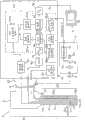
如图11所示,电子内窥镜系统1C包括:实施例3的电子内窥镜2C;供给该电子内窥镜2C照明光的光源装置3;对内置在电子内窥镜2C中的摄像单元进行信号处理的图像处理装置(信号处理装置)4C;被输入从图像处理装置4C输出的标准视频信号,从而显示内窥镜图像的对应于高清晰TV(简记为HDTV)方式的监视器5。As shown in FIG. 11 , anelectronic endoscope system 1C includes: an electronic endoscope 2C according toEmbodiment 3; alight source device 3 for supplying illumination light to the electronic endoscope 2C; and an imaging unit built in the electronic endoscope 2C. An image processing device (signal processing device) 4C that performs signal processing; amonitor 5 corresponding to a high-definition TV (abbreviated as HDTV) system that displays an endoscopic image by inputting the standard video signal output from the image processing device 4C .

本实施例的电子内窥镜2C具有:插入被检测体的细长的插入部7;设置在该插入部7的后端,由手术人员等操作者抓持进行操作的操作部8;以及从该操作部8延伸出来的电缆部9。The electronic endoscope 2C of this embodiment has: anelongated insertion portion 7 for insertion into the subject; anoperation portion 8 provided at the rear end of theinsertion portion 7 and operated by an operator such as an operator; Acable portion 9 extends from theoperation portion 8 .

插入部7的前端设置有硬质的前端部11,在该前端部11上设置有后述的摄像单元119等。A rigiddistal end portion 11 is provided at the distal end of theinsertion portion 7 , and animaging unit 119 , which will be described later, and the like are provided on thedistal end portion 11 .

插入部7内插通有传送照明光的光导14,该光导14的后端侧通过电缆部9到达设置于该光导14的端部上的光导连接器15。操作者通过将该光导连接器15连接到光源装置3,从而从光源装置3向光导14的后端面提供照明光。Alight guide 14 for transmitting illumination light is inserted into theinsertion portion 7 , and the rear end side of thelight guide 14 reaches thelight guide connector 15 provided at the end of thelight guide 14 through thecable portion 9 . The operator connects thelight guide connector 15 to thelight source device 3 to supply illumination light from thelight source device 3 to the rear end surface of thelight guide 14 .

从光源装置3供给的照明光由光导14传送,从固定于前端部11上的前端面进一步经过与该前端面对置地安装在照明窗上的照明透镜16a、16b(参考图14)向前方射出,照明体腔内的患部等被拍摄物体。前端部11上与照明窗相邻设置有观察窗(或摄像窗),在该摄像窗上配置有摄像单元119,该摄像单元119包括对被照明的被拍摄物体成光学像的物镜系统(或物镜光学系统)117;和受光面(或光电转换面)配置在该物镜系统117的成像位置上的作为摄像元件的例如电荷耦合元件(简记作CCD)118。The illumination light supplied from thelight source device 3 is transmitted by thelight guide 14, and is emitted forward from the front end surface fixed to thefront end portion 11 throughillumination lenses 16a, 16b (see FIG. 14 ) mounted on the illumination window facing the front end surface. , to illuminate the affected part in the body cavity and other objects to be photographed. An observation window (or imaging window) is arranged adjacent to the illumination window on thefront end portion 11, and animaging unit 119 is arranged on the imaging window. objective optical system) 117; and a charge-coupled device (abbreviated as CCD) 118 as an imaging element, for example, a light-receiving surface (or a photoelectric conversion surface) disposed on the imaging position of theobjective lens system 117.

摄像单元119上连接着信号电缆21的一端,插通到插入部7内的信号电缆21还插通到电缆部9内,该信号电缆21的另一端连接在其后端的信号连接器22上。One end of asignal cable 21 is connected to thecamera unit 119, and thesignal cable 21 inserted into theinsertion portion 7 is also inserted into thecable portion 9, and the other end of thesignal cable 21 is connected to asignal connector 22 at the rear end thereof.

通过将该信号连接器22连接于图像处理装置4C上,通过来自图像处理装置4C的CCD驱动部23的CCD驱动信号来驱动CCD 118,CCD 118输出进行了光电转换的图像信号(摄像信号)。By connecting thesignal connector 22 to the image processing device 4C, theCCD 118 is driven by a CCD drive signal from theCCD drive unit 23 of the image processing device 4C, and theCCD 118 outputs a photoelectrically converted image signal (image pickup signal).

该摄像信号在图像处理装置4C内被进行信号处理,生成视频信号,在监视器5上显示内窥镜图像。The imaging signal is subjected to signal processing in the image processing device 4C to generate a video signal, and an endoscopic image is displayed on themonitor 5 .

此外,在插入部7内设置有各种处理器具可插通于其中的通道25。该通道25包括在前端部11开口的通道前端开口(也称作前端开口或钳子口)26、操作部8的前端附近的处理器具插入口27、连接前端开口26和处理器具插入口27的通道管25a。In addition, achannel 25 through which various treatment tools can be inserted is provided in theinsertion portion 7 . Thechannel 25 includes a channel front end opening (also referred to as a front opening or forceps opening) 26 opened at thefront end portion 11, a treatmenttool insertion port 27 near the front end of theoperation portion 8, and a channel connecting thefront end opening 26 and the treatmenttool insertion port 27. Tube 25a.

并且,通过从该处理器具插入口27插入处理器具28,使该处理器具28的前端侧从前端开口26突出,可以在处理器具28的前端侧进行采集、切除患部组织等的处理。Furthermore, by inserting thetreatment tool 28 from the treatmenttool insertion port 27 and making the front end of thetreatment tool 28 protrude from thefront end opening 26 , it is possible to collect and excise affected tissue at the front end of thetreatment tool 28 .

此外,本实施例中,从前端开口26突出的处理器具28的前端侧与患部组织等作为检查对象或处理对象的被拍摄物体一起,进入到摄像单元119的视野内,该突出的处理器具28显示在监视器5的显示面上,可顺利地进行处理等。In addition, in this embodiment, the front end side of thetreatment tool 28 that protrudes from the front end opening 26 enters the field of view of theimaging unit 119 together with the affected tissue and other objects to be inspected or treated. The protrudingtreatment tool 28 Displayed on the display surface of themonitor 5, processing and the like can be performed smoothly.

本实施例中,CCD 118是具有补色系的马赛克滤色器的马赛克滤色方式的CCD,采用像素间距是2.5μm、对监视器显示有效的像素数是130万像素的CCD。In the present embodiment,CCD 118 is the CCD of the mosaic color filter mode that has the mosaic color filter of complementary color system, adopts the CCD that the pixel pitch is 2.5 μm, and the number of pixels effective for monitor display is 1.3 million pixels.

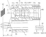
上述摄像单元119使用由最大视场角为例如120°~140°左右的、在改变焦点位置的情况下视场角几乎不变的由可变焦点光学系统构成的物镜系统117,如使用图12说明的那样,通过致动器129在物镜系统117的光轴O上前后移动接合透镜117d,如图13所示,从近景(近点侧)到远景(远点侧)都能够以高分辨率在CCD 118上成像。The above-mentionedimaging unit 119 uses anobjective lens system 117 composed of a variable focus optical system whose maximum viewing angle is, for example, about 120° to 140°, and the viewing angle is almost unchanged when the focus position is changed, as shown in FIG. 12 . As explained, the cementedlens 117d is moved back and forth on the optical axis O of theobjective lens system 117 by theactuator 129, as shown in FIG. Imaging onCCD 118.

该物镜系统117设定成Fno(F号码)为例如小于等于10.0左右,以便不超出光的衍射界限。并设定成当为近景时的物距时可得到最高分辨率。Theobjective lens system 117 is set such that Fno (F number) is, for example, about 10.0 or less so as not to exceed the diffraction limit of light. And set it so that the highest resolution can be obtained when the object distance is close-up.

使用图12说明本实施例的摄像单元119的结构。The structure of theimaging unit 119 of this embodiment is demonstrated using FIG. 12. FIG.

构成物镜系统117的前级的多个透镜(含光学元件)117a、117b、117c被固定于透镜框31上,以使得面间隔适当并且各透镜对中。A plurality of lenses (including optical elements) 117a, 117b, and 117c constituting the front stage of theobjective lens system 117 are fixed to thelens frame 31 so that the distance between the surfaces is appropriate and the lenses are centered.

图12的情况下,通过隔离件32来设定透镜117b和117c之间的面间隔。构成物镜系统117、从前端侧开始按顺序配置的第一、第二、第三透镜117a、117b、117c分别是平凹透镜、双凸透镜、红外截止滤色器。In the case of FIG. 12 , thespacer 32 sets the distance between the surfaces of thelenses 117 b and 117 c. The first, second, andthird lenses 117a, 117b, and 117c that constitute theobjective lens system 117 and are arranged sequentially from the front end are plano-concave lenses, biconvex lenses, and infrared cut filters, respectively.

在嵌合于该框31中的CCD框133内,沿物镜系统117的光轴O方向可自由滑动地设置有保持接合透镜117d的透镜保持框部134a。In theCCD frame 133 fitted in theframe 31 , a lensholding frame portion 134 a holding the cementedlens 117 d is slidably provided in the direction of the optical axis O of theobjective lens system 117 .

该CCD框133内,在透镜保持框部134a的后方侧位置上固定着平行平板透镜117e和CCD芯片118b。In theCCD frame 133, aparallel plate lens 117e and aCCD chip 118b are fixed at positions on the rear side of the lens holdingframe portion 134a.

CCD 118由密封玻璃118a、由该密封玻璃118a保护受光面(摄像面)的CCD芯片118b、与CCD芯片118b连接的CCD基板118c、安装在该CCD基板118c上的CCD驱动用部件118d构成。TheCCD 118 consists of a sealingglass 118a, aCCD chip 118b protecting the light-receiving surface (imaging surface) by the sealingglass 118a, aCCD substrate 118c connected to theCCD chip 118b, and aCCD drive component 118d mounted on theCCD substrate 118c.

CCD基板118c通过凸块连接等与CCD芯片118b电连接。CCD基板118c上焊接有耦合电容器、电流放大用晶体管等CCD驱动用部件118d。CCD芯片118b的受光面上通过光学粘接剂等粘接固定着用于保护该受光面的密封玻璃118a。TheCCD substrate 118c is electrically connected to theCCD chip 118b by bump connection or the like.CCD driving components 118d such as coupling capacitors and current amplification transistors are soldered to theCCD substrate 118c. On the light receiving surface of theCCD chip 118b, a sealingglass 118a for protecting the light receiving surface is bonded and fixed with an optical adhesive or the like.

透镜框31与CCD框133嵌合,使得透镜框31可与物镜系统117的光轴方向平行地移动,把CCD芯片118b粘接固定在CCD框133上,以使得上述物镜系统117的光轴与上述CCD芯片118b的受光面垂直。Lens frame 31 is fitted withCCD frame 133, so thatlens frame 31 can move parallel to the optical axis direction ofobjective lens system 117,CCD chip 118b is bonded and fixed on theCCD frame 133, so that the optical axis of above-mentionedobjective lens system 117 and The light receiving surface of theCCD chip 118b is vertical.

本实施例中,配置在CCD框133内的例如具有正的放大率(折射力)的接合透镜117d被与CCD框133的内周面嵌合可自由移动的透镜保持框部134a保持,该透镜保持框部134a经过贯通于设置在CCD框133上的长槽133a内的臂部134b,与CCD框133外部的致动器连接部134c连接。In this embodiment, the cementedlens 117d having, for example, a positive magnification (refractive power) arranged in theCCD frame 133 is held by a lensholding frame portion 134a fitted with the inner peripheral surface of theCCD frame 133 and freely movable. The holdingframe part 134a is connected to theactuator connection part 134c outside theCCD frame 133 via thearm part 134b penetrating in the long groove 133a provided in theCCD frame 133 .

由上述透镜保持框部134a、臂部134b和致动器连接部134c形成用于移动接合透镜117d的移动透镜框134。Amovable lens frame 134 for moving the cementedlens 117d is formed by the above-described lensholding frame portion 134a,arm portion 134b, andactuator connection portion 134c.

通过致动器连接部134c与移动透镜框134一起来移动接合透镜117d的致动器129由与致动器连接部134c连接的致动器移动部129a、将该致动器移动部129a沿与物镜系统117的光轴O平行的方向移动的致动器主体129b构成。该致动器主体129b固定在CCD框133的外周侧。Theactuator 129 that moves the cementedlens 117d together with the movinglens frame 134 through theactuator connecting portion 134c is connected to the actuator moving portion 129a along theactuator connecting portion 134c. The actuatormain body 129b that moves in a direction parallel to the optical axis O of theobjective lens system 117 is constituted. The actuatormain body 129b is fixed on the outer peripheral side of theCCD frame 133 .

该致动器主体129b经过信号线135与设置在图像处理装置4C内的致动器驱动部136(参考图11)连接,通过来自该致动器驱动部136的致动器驱动信号,致动器主体129b动作。The actuatormain body 129b is connected to the actuator driving unit 136 (refer to FIG. 11 ) provided in the image processing device 4C via thesignal line 135, and is actuated by the actuator driving signal from theactuator driving unit 136. The devicemain body 129b moves.

致动器主体129b可以对应于该致动器驱动信号而使致动器移动部129a向成为致动器主体129b侧的后方侧移动,或使其向离开致动器主体129b的前方侧移动。该致动器驱动部136产生(输出)与来自构成设置在图像处理装置4C内的自动对焦部(本实施例的对焦控制部)137的CPU137c的控制信号对应的致动器驱动信号。The actuatormain body 129b can move the actuator moving part 129a to the rear side of the actuatormain body 129b side or to the front side away from the actuatormain body 129b in response to the actuator driving signal. Theactuator drive unit 136 generates (outputs) an actuator drive signal corresponding to a control signal from a CPU 137c constituting an autofocus unit (focus control unit in this embodiment) 137 provided in the image processing device 4C.

图12所示状态下,接合透镜117d为设定在可动范围(移动范围)的大致中央附近的状态,在通过致动器驱动信号而向最前方侧移动了的近景时的设定状态时,接合透镜117d设定在图13的双点划线所示位置处,该状态下,变成对焦于近点侧的近景以景深为5.2mm~10mm的范围以高分辨率成像在CCD芯片118b上的状态。In the state shown in FIG. 12 , the cementedlens 117d is set in the vicinity of the approximate center of the movable range (moving range), and in the close-up state where it is moved to the frontmost side by the actuator drive signal. , the cementedlens 117d is set at the position indicated by the two-dot chain line in FIG. on status.

在通过致动器驱动信号而向最后方侧移动的情况下,接合透镜117d被设定在图13的实线所示的最后方侧的位置处,该状态是成为远点侧的远景时的设定状态。该远景时的设定状态下,变成对焦于远景,且远景以规定分辨率并以景深为10mm~100mm的大状态成像在CCD芯片118b上的状态。When moving toward the rearmost side by the actuator drive signal, the cementedlens 117d is set at the rearmost position shown by the solid line in FIG. Set state. In this setting state at the time of the distant view, the distant view is focused on, and the distant view is imaged on theCCD chip 118 b with a predetermined resolution and a large depth of field of 10 mm to 100 mm.

这样,接合透镜117d将近景位置到远景位置作为可动范围,可移动设定在该可动范围内的任意位置处。图13是动作说明图,仅对部分构成要素标注标号来进行表示。In this way, the cementedlens 117d has a movable range from the close-up position to the far-view position, and can be moved to any position within the movable range. FIG. 13 is an operation explanatory diagram, in which only some constituent elements are indicated with reference numerals.

如图12所示,CCD基板118c上设置有用于焊接信号电缆21的信号线的焊盘(未示出),信号电缆21的信号线被焊接。从CCD框133经过CCD芯片118b,到信号电缆21的与CCD基板118c的连接部,配置有进行机械保护的CCD保护框138。As shown in FIG. 12 , pads (not shown) for welding the signal lines of thesignal cable 21 are provided on theCCD substrate 118c, and the signal lines of thesignal cable 21 are welded. From theCCD frame 133 through theCCD chip 118b to the connection portion of thesignal cable 21 to theCCD substrate 118c, aCCD protection frame 138 for mechanical protection is disposed.

在该CCD保护框138上,在成为CCD芯片118b的背面部附近的位置处设置有切口部,以从该切口部插入的方式配置有由导热性好的例如铝合金、铜合金等形成的散热部件139。该散热部件139上通过焊接、粘接剂等机械连接着以导热性好的金属为导体的散热用电缆140。On thisCCD protection frame 138, a notch is provided at a position near the rear surface of theCCD chip 118b, and a radiator made of aluminum alloy, copper alloy, etc. with good thermal conductivity is arranged to be inserted from the notch.Part 139. Aheat dissipation cable 140 having a metal with good thermal conductivity as a conductor is mechanically connected to theheat dissipation member 139 by welding, adhesive, or the like.

CCD保护框138内部填充有密封树脂141,用具有热收缩性的管142密封CCD芯片118b周边。散热用电缆140焊接在热容量大的部件,如插入部7的前端部11上。The inside of theCCD protection frame 138 is filled with a sealingresin 141 , and the periphery of theCCD chip 118 b is sealed with a heat-shrinkable tube 142 . Theheat dissipation cable 140 is welded to a component with a large heat capacity, such as thefront end portion 11 of theinsertion portion 7 .

信号电缆21是按如下形成的,将多个同轴线和多个单线合在一起,然后卷绕氟树脂制的带子,在其上缠绕铜线作为统一屏蔽,再在其上卷绕氟树脂制的带子,再在其上用特氟纶(テフロン)(注册商标)类护套覆盖。Thesignal cable 21 is formed by combining a plurality of coaxial wires and a plurality of single wires together, then winding a tape made of fluororesin, winding a copper wire on it as a unified shield, and winding a fluororesin thereon A belt made of a Teflon (Teflon) (registered trademark) type sheath is used to cover it.

如图14所示,插入部7的前端部11配置有:包含前端第一透镜117a的外径为例如φ2.8mm的物镜系统117的摄像单元119;通道前端开口26;去除在物镜系统117的外表面上因送气送水而造成的附着污物的送气送水喷嘴143;利用通过与光源装置3连接的光导14传送(导光)的光来照明被拍摄物体的照明透镜16a、16b。As shown in Figure 14, thefront end portion 11 ofinsertion part 7 is equipped with: the outer diameter that comprises the front endfirst lens 117a is theimaging unit 119 of theobjective lens system 117 such as φ 2.8mm; Channelfront end opening 26; The air andwater nozzles 143 for attaching dirt due to air and water on the outer surface; theillumination lenses 16a, 16b for illuminating the object to be photographed by the light transmitted (guided) by thelight guide 14 connected to thelight source device 3 .

摄像单元119在前端部11上被安装成使得当拍摄对被拍摄物体、显示在监视器5上时的监视器5上的上下方向与图14所示的插入部7的前端部11的上下方向一致。本实施例的通道管25a使用例如特氟纶(注册商标)制的内径2.8mm的管。Thecamera unit 119 is mounted on thefront end portion 11 so that the up-down direction on themonitor 5 when the subject is photographed and displayed on themonitor 5 is the same as the up-down direction of thefront end portion 11 of theinsertion portion 7 shown in FIG. 14 . unanimous. For the channel tube 25a of this embodiment, for example, a tube with an inner diameter of 2.8 mm made of Teflon (registered trademark) is used.

如图15所示,物镜系统117的光轴O与(通道管25a的前端所连接的)前端开口26平行地配置,本实施例中,物镜系统117的中心(光轴O)与前端开口26的中心轴的距离D被设定为例如6mm。该前端开口26的半径R的2倍与通道管25a的内径相同,是2.8mm。As shown in Figure 15, the optical axis O of theobjective lens system 117 is configured parallel to the front end opening 26 (connected to the front end of the channel pipe 25a). The distance D of the central axis is set to be, for example, 6 mm. Twice the radius R of the front end opening 26 is 2.8 mm, which is the same as the inner diameter of the channel pipe 25 a.

如图11所示,光源装置3有灯40,利用由光圈驱动部41驱动的光圈42的开口调整了该灯40的照明光的透过光量后,该灯40的照明光经过会聚透镜43入射到光导连接器15上的光导14的入射端面上。并且,如上所述,从光导14的前端,再经过照明透镜16a、16b向被拍摄物体侧射出照明光。As shown in Figure 11, thelight source device 3 has alamp 40, and after the aperture of theaperture 42 driven by theaperture drive unit 41 is used to adjust the transmitted light amount of the illumination light of thelamp 40, the illumination light of thelamp 40 is incident through a condensinglens 43. to the incident end face of thelight guide 14 on thelight guide connector 15 . Furthermore, as described above, the illumination light is emitted from the front end of thelight guide 14 to the subject side through theillumination lenses 16a and 16b.

光导14在插入部7内分支为两条,如图14所示,从在前端部11配置在2个部位上的照明透镜16a、16b分别射出照明光。Thelight guide 14 is branched into two in theinsertion part 7, as shown in FIG.

如图11所示,图像处理装置4C中具有被输入来自CCD 118的图像信号的CDS电路44,由该CDS电路44提取出信号成分后,由A/D转换器45转换为数字信号。As shown in FIG. 11 , the image processing device 4C has aCDS circuit 44 to which an image signal from theCCD 118 is input, and after the signal component is extracted by theCDS circuit 44, it is converted into a digital signal by an A/D converter 45.

由该A/D转换器45转换的数字图像信号输入生成由亮度信号和颜色信号构成的视频信号的信号转换部46。通过该信号转换部46生成的视频信号输入进行γ校正等各种图像处理的图像处理部47。该图像处理部47的输出信号输入D/A转换器48,转换为模拟的与HDTV方式对应的视频信号后,输出到监视器5。The digital image signal converted by the A/D converter 45 is input to asignal conversion unit 46 that generates a video signal composed of a luminance signal and a color signal. The video signal generated by thesignal conversion unit 46 is input to animage processing unit 47 that performs various image processing such as gamma correction. The output signal of theimage processing unit 47 is input to the D/A converter 48 , converted into an analog video signal corresponding to the HDTV system, and output to themonitor 5 .

来自信号转换部46的亮度信号被输入生成自动调光信号的自动调光部54,通过该自动调光部54生成自动调光信号。该自动调光部54包括:检测处理器具的处理器具检测部54a;检测从该处理器具检测部54a输入的亮度信号的平均水平的亮度检测部54b;将检测出的亮度信号的平均水平与成为基准的基准值进行比较,并将与基准值的差信号作为自动调光信号输出的调光信号生成部54c。The luminance signal from thesignal conversion unit 46 is input to anautomatic dimming unit 54 that generates an automatic dimming signal, and theautomatic dimming unit 54 generates an automatic dimming signal. Theautomatic dimming unit 54 includes: a treatment instrument detection unit 54a for detecting a treatment instrument; abrightness detection unit 54b for detecting an average level of a brightness signal input from the treatment instrument detection unit 54a; Thedimming signal generator 54c compares the reference value of the reference and outputs a difference signal with the reference value as an automatic dimming signal.

处理器具检测部54a通过例如处理器具的反射光量和颜色,来检测出处理器具进入摄像单元119的视野内(换言之,处理器具的图像成像在CCD118的受光面上)的情况。The treatment instrument detection unit 54 a detects that the treatment instrument enters the field of view of the imaging unit 119 (in other words, the image of the treatment instrument is imaged on the light receiving surface of the CCD 118 ) based on, for example, the amount and color of reflected light of the treatment instrument.

亮度检测部54b在处理器具检测部54a检测到处理器具的情况下,检测出处理器具的像所成像的区域附近的峰值亮度(光量)和该区域附近的平均亮度(光量)。When the treatment tool detection unit 54a detects a treatment tool, theluminance detection unit 54b detects the peak luminance (light intensity) near the area where the image of the treatment tool is formed and the average luminance (light amount) around the area.

该亮度检测部54b在处理器具检测部54a未检测到处理器具的情况下,检测画面整体的峰值亮度和平均亮度。Theluminance detection unit 54b detects the peak luminance and the average luminance of the entire screen when the treatment tool detection unit 54a has not detected a treatment tool.

调光信号生成部54c为了通过来自亮度检测部54b的峰值亮度和平均亮度信号而得到适当亮度的信号,生成用于调整光源装置3的照明光量的自动调光信号,输出到光源装置3的光圈驱动部41。Thedimming signal generator 54c generates an automatic dimming signal for adjusting the amount of illumination light of thelight source device 3 in order to obtain a signal of appropriate brightness from the peak brightness and the average brightness signal from thebrightness detector 54b, and outputs it to the aperture of thelight source device 3.drive unit 41 .

自动调光部54的自动调光信号输入到光源装置3的光圈驱动部41,对应于自动调光信号,光圈驱动部41自动调整光圈42的开口量,进行控制以得到相当于调光信号生成部54c的基准值的适合于观察的亮度的图像。The automatic dimming signal of theautomatic dimming part 54 is input to theaperture driving part 41 of thelight source device 3, corresponding to the automatic dimming signal, theaperture driving part 41 automatically adjusts the opening amount of theaperture 42, and performs control to obtain the corresponding dimming signal generation. An image of the brightness suitable for observation of the reference value of theportion 54c.

信号检测部46的亮度信号被输入构成自动对焦部137的亮度检测部137a,由亮度检测部137a检测出图像的亮度。The luminance signal of thesignal detection unit 46 is input to a luminance detection unit 137a constituting theautofocus unit 137, and the luminance of the image is detected by the luminance detection unit 137a.

图像处理部47的输出信号被输入构成自动对焦部137的对比度检测部137b,由对比度检测部137b检测输出信号的对比度。The output signal of theimage processing unit 47 is input to thecontrast detection unit 137b constituting theautofocus unit 137, and the contrast of the output signal is detected by thecontrast detection unit 137b.

由亮度检测部137a检测出的亮度信息和由对比度检测部137b检测出的对比度信息被输入CPU 137c,该CPU 137c通过亮度信息和对比度信息进行例如登山方式的自动对焦控制(在后面利用图16进行说明)。The brightness information detected by the brightness detection unit 137a and the contrast information detected by thecontrast detection unit 137b are input to the CPU 137c, and the CPU 137c uses the brightness information and the contrast information to perform, for example, automatic focus control in a mountain climbing mode (to be performed later using FIG. 16 ). illustrate).

本实施例的电子内窥镜2C采用可变焦点光学系统(即焦点位置可变的光学系统),所述可变焦点光学系统将物镜系统117中的一部分的接合透镜117d配置成可沿光轴O的方向自由移动,可在近景时的位置到远景时的位置的范围内连续移动,对应于该移动,视场角几乎不变化,而焦距改变。The electronic endoscope 2C of this embodiment employs a variable focus optical system (that is, an optical system in which the focus position is variable) that arranges a part of the cementedlens 117d of theobjective lens system 117 so that it can move along the optical axis. The direction of O can be freely moved, and can be continuously moved within the range from the position of the near view to the position of the distant view. According to this movement, the angle of view hardly changes, but the focal length changes.

并且,由自动对焦部137控制该接合透镜117d,能够始终在从近景到远景的范围内设定成对焦状态、以保持高分辨率和规定景深的状态进行拍摄。In addition, the cementedlens 117d is controlled by theautofocus unit 137, and can always be set in a focused state from a close-up to a distant view, and can be photographed while maintaining a high resolution and a predetermined depth of field.

本实施例中,如以下说明的那样,构成为即使设定成近景的情况下,也能确保宽的视野角(视场角),即使使用处理器具时,从通道25的前端开口26突出的处理器具的前端侧也进入视野内,容易进行详细的处理。In this embodiment, as will be described below, it is configured to ensure a wide viewing angle (viewing angle) even when it is set to a close-up view, and even when a treatment instrument is used, the front end opening 26 of thechannel 25 protrudes The distal end side of the treatment instrument is also in the field of view, making it easy to perform detailed treatment.

具体说,本实施例中,在插通于通道25内的处理器具28的前端侧从前端开口26突出的情况下,在物距为可获得能识别例如35μm间距的黑白色的高分辨率的近景侧的物距(被拍摄物体物距)时,处理器具28的前端侧进入摄像单元119的视野内,换言之,在CCD 118的受光面上成像处理器具28的前端侧的像。Specifically, in this embodiment, when the front end side of thetreatment tool 28 inserted into thechannel 25 protrudes from thefront opening 26, when the object distance is such that black and white high-resolution images can be recognized at a pitch of 35 μm, for example, When the object distance on the close-range side (object distance to be photographed), the front end side of thetreatment tool 28 enters the field of view of theimaging unit 119, in other words, the image of the front end side of thetreatment tool 28 is formed on the light receiving surface of theCCD 118.

下面说明这种结构的本实施例的作用。The action of this embodiment of such a structure will be described below.

如图11所示,将电子内窥镜2C的光导连接器15连接到光源装置3,将信号连接器22连接到图像处理装置4C。该图像处理装置4C的视频输出端上连接监视器5的电缆,设成可进行内窥镜检查的状态。As shown in FIG. 11 , thelight guide connector 15 of the electronic endoscope 2C is connected to thelight source device 3 , and thesignal connector 22 is connected to the image processing device 4C. The cable of themonitor 5 is connected to the video output terminal of the image processing device 4C, so that endoscopic examination can be performed.

并且,将未示出的电源开关接通,来自光源装置3的照明光提供给光导14,通过光导14将照明光从照明透镜16a、16b射出,设为可照明由摄像单元119拍摄的被拍摄物体的状态。通过摄像单元119的CCD 118拍摄的图像成为通过图像处理装置4C显示在监视器5上的状态。And, the power switch not shown is turned on, and the illumination light from thelight source device 3 is supplied to thelight guide 14, and the illumination light is emitted from theillumination lenses 16a, 16b through thelight guide 14, so as to illuminate the subject photographed by theimaging unit 119. the state of the object. The image captured by theCCD 118 of theimaging unit 119 is displayed on themonitor 5 by the image processing device 4C.

接着将电子内窥镜2C的插入部7插入患者体腔内,将插入部7的前端部11设成可观察体腔内的患部等作为要进行内窥镜检查的部位的被拍摄物体的状态。此时,设置于前端部11上的摄像单元119的物镜系统117将被拍摄物体的光学像成像在CCD 118的受光面上。在CCD 118的受光面上成像的像被光电转换,转换为图像信号。Next, theinsertion part 7 of the electronic endoscope 2C is inserted into the patient's body cavity, and thefront end part 11 of theinsertion part 7 is set in a state where an object to be photographed such as an affected part in the body cavity can be observed. At this time, theobjective lens system 117 of thecamera unit 119 arranged on thefront end portion 11 forms an optical image of the object to be photographed on the light-receiving surface of theCCD 118. The image formed on the light-receiving surface of theCCD 118 is photoelectrically converted into an image signal.

该图像信号经过信号电缆21、信号连接器22输入图像处理装置4C的CDS电路44。该图像信号的波形包含信号成分以外的复位噪声等,通过CDS电路44生成信号成分被提取的基带信号。The image signal is input to theCDS circuit 44 of the image processing device 4C via thesignal cable 21 and thesignal connector 22 . The waveform of this image signal includes reset noise and the like other than the signal components, and theCDS circuit 44 generates a baseband signal from which the signal components are extracted.

该CDS电路44的输出信号输入A/D转换器45,A/D转换器45将作为模拟信号的图像信号转换为数字信号。转换为数字信号的图像信号由信号转换部46转换为视频信号。The output signal of thisCDS circuit 44 is input to the A/D converter 45, and the A/D converter 45 converts the image signal which is an analog signal into a digital signal. The image signal converted into a digital signal is converted into a video signal by thesignal conversion unit 46 .

此时,由于本实施例中采用补色系的马赛克滤色器作为CCD 118,因此该信号转换部46转换为从例如相邻的4种滤色器的像素信号输出取平均而得到的亮度信号、由各色的像素信号输出的差分得到的色差信号这样的视频信号。At this time, since the mosaic color filter of the complementary color system is adopted as theCCD 118 in the present embodiment, thesignal conversion unit 46 is converted into a luminance signal obtained by averaging the pixel signal outputs of, for example, adjacent four kinds of color filters, A video signal such as a color-difference signal obtained by outputting a difference of pixel signals of each color.

该视频信号被图像处理部47进行适合于监视器显示的对比度调整、颜色调整和显示尺寸调整等。This video signal is subjected to contrast adjustment, color adjustment, display size adjustment, and the like suitable for monitor display by theimage processing unit 47 .

之后,由D/A转换器48转换为监视器5可显示的模拟的对应于HDTV方式的视频信号。监视器5在监视器画面5a上显示与输入的HDTV方式的视频信号对应的(由CCD 118拍摄的)被拍摄物体图像。Thereafter, it is converted by the D/A converter 48 into an analog video signal corresponding to the HDTV system that can be displayed on themonitor 5 . Themonitor 5 displays an object image (photographed by the CCD 118) corresponding to the input video signal of the HDTV system on themonitor screen 5a.

首先说明自动调光功能。First, the automatic dimming function will be described.

自动调光部54在处理器具28未进入摄像单元119的视野内的情况下,由亮度检测部54b检测出画面整体的亮度(具体说是峰值亮度或平均亮度),输出给调光信号生成部54c。该调光信号生成部54c在画面暗时向光源装置3输出控制信号,具体说是自动调光信号,以增大发光。在画面过于明亮的情况下,输出作为控制光源装置3以减小发光的控制信号的自动调光信号。When thetreatment instrument 28 does not enter the field of view of theimaging unit 119, theautomatic dimming unit 54 detects the brightness of the entire screen (specifically, peak brightness or average brightness) by thebrightness detection unit 54b, and outputs it to the dimming signal generation unit. 54c. Thedimming signal generator 54c outputs a control signal, specifically an automatic dimming signal, to thelight source device 3 to increase light emission when the screen is dark. When the screen is too bright, an automatic dimming signal is output as a control signal for controlling thelight source device 3 to reduce light emission.

通过该自动调光信号,光源装置3内的光圈驱动部41驱动光圈42,调整从灯40经过光圈42入射到光导14的后端的照明光量,以成为合适的光量。Theaperture driving unit 41 in thelight source device 3 drives theaperture 42 based on the automatic dimming signal, and adjusts the amount of illumination light entering the rear end of thelight guide 14 from thelamp 40 through theaperture 42 to an appropriate light amount.

接着说明为了通过利用摄像单元119的内窥镜观察,对患部等被拍摄物体进行治疗用的组织采集和病变部切除,而使用处理器具28的情况下的自动调光的作用。Next, the function of the automatic light adjustment in the case of using thetreatment tool 28 for performing tissue harvesting for treatment and excision of a lesion on an object to be photographed such as an affected part through endoscopic observation by theimaging unit 119 will be described.

通过将处理器具28插入通道25,使处理器具28经过插入部7的前端部11的前端开口26,从其前端面突出,从而使处理器具进入摄像单元119的视野内。By inserting thetreatment tool 28 into thechannel 25 , thetreatment tool 28 passes through thefront opening 26 of thefront end portion 11 of theinsertion part 7 and protrudes from the front end thereof, so that thetreatment tool 28 enters the field of view of theimaging unit 119 .

此时,例如根据处理器具28的颜色、处理器具28的反射光等,处理器具检测部54a检测出处理器具28进入了视野内,检测出基于以上述处理器具28为中心的一定区域的峰值亮度和平均亮度的亮度。调光信号生成部54c输出作为控制信号的自动调光信号,以便当上述处理器具28附近的亮度过亮时使光源装置3减小发光,过暗时使光源装置3增大发光。At this time, for example, based on the color of thetreatment tool 28, reflected light from thetreatment tool 28, etc., the treatment tool detection unit 54a detects that thetreatment tool 28 has entered the field of view, and detects the peak luminance based on a certain area centered on thetreatment tool 28. and the brightness of the average brightness. Thedimming signal generator 54c outputs an automatic dimming signal as a control signal to reduce the light emission of thelight source device 3 when the brightness near thetreatment tool 28 is too bright, and to increase the light emission of thelight source device 3 when it is too dark.

并且,通过自动调光信号,光源装置3内的光圈驱动部41驱动光圈42,调整从灯40通过光圈42入射到光导14的入射端的照明光量。通过该自动调光信号,可进行自动调光,使得处理器具28进入摄像单元119的视野内的区域附近的亮度为适合于观察的亮度。In addition, theaperture driving unit 41 in thelight source device 3 drives theaperture 42 based on the automatic dimming signal, and adjusts the amount of illumination light incident on the incident end of thelight guide 14 from thelamp 40 through theaperture 42 . With this automatic dimming signal, automatic dimming can be performed so that the brightness around the area where thetreatment tool 28 enters the field of view of theimaging unit 119 becomes a brightness suitable for observation.

本实施例中,通过自动对焦部137进行控制,使构成物镜系统117的接合透镜117d始终在对焦状态下在CCD 118的受光面上成像拍摄物体像。In this embodiment, theautofocus unit 137 controls so that the cementedlens 117d constituting theobjective lens system 117 forms an object image on the light-receiving surface of theCCD 118 in an in-focus state.

此时,自动对焦部137的亮度检测部137a从来自信号转换部46的亮度信号中检测出各帧的平均亮度,输出到CPU 137c。对比度检测部137b从图像处理部47的输出信号中的高频域侧的亮度信号中检测出各帧的对比度,输出到CPU 137c。At this time, the brightness detection unit 137a of theauto focus unit 137 detects the average brightness of each frame from the brightness signal from thesignal conversion unit 46, and outputs it to the CPU 137c. Thecontrast detection unit 137b detects the contrast of each frame from the luminance signal on the high-frequency side of the output signal from theimage processing unit 47, and outputs it to the CPU 137c.

CPU 137c判断由亮度检测部137a检测出的亮度是否在规定值以上,在超过规定值的情况下,通过基于由对比度检测部137b检测出的高频域侧的亮度信号的对比度信息,按登山方式检测出对焦状态,将接合透镜117d设置于对焦状态的位置上。The CPU 137c judges whether the luminance detected by the luminance detection unit 137a is above a predetermined value, and if the luminance exceeds the predetermined value, the CPU 137c performs a mountain climbing method based on the contrast information based on the luminance signal on the high-frequency side detected by thecontrast detection unit 137b. The in-focus state is detected, and the cementedlens 117d is set at the position of the in-focus state.

图16表示登山方式的自动对焦(图16中简记作AF)的处理内容。FIG. 16 shows the processing contents of the autofocus (abbreviated as AF in FIG. 16 ) in the mountain climbing mode.

首先,最初的步骤S1中,CPU 137c进行透镜移动方向的判断。如图12和图13所示,判断在进行该登山方式的自动对焦时的开始的透镜位置处,哪个方向为登山方向(对比度增大的方向)。First, in the first step S1, the CPU 137c judges the moving direction of the lens. As shown in FIGS. 12 and 13 , it is determined which direction is the climbing direction (the direction in which the contrast increases) at the initial lens position when autofocusing in the climbing method is performed.

具体说,CPU 137c控制致动器驱动部136,通过致动器129向一个方向移动接合透镜117d,此时判断移动前后从对比度检测部137b输出的对比度信息是否增大。并且,CPU 137c将对比度增大的方向判断为透镜移动方向,使接合透镜117d向该方向移动。Specifically, the CPU 137c controls theactuator drive unit 136 to move the cementedlens 117d in one direction through theactuator 129, and at this time, it is judged whether the contrast information output from thecontrast detection unit 137b increases before and after the movement. Then, the CPU 137c determines the direction in which the contrast increases as the lens moving direction, and moves the cementedlens 117d in that direction.

并且接着的步骤S2中,CPU 137c检测出接合透镜117d向对比度增大的方向移动了时的对比度的峰值。当向对比度增大的登山方向移动、超过对焦位置时,此时的对比度值比峰值小。And in the next step S2, the CPU 137c detects the peak value of the contrast when the cementedlens 117d moves in the direction of increasing the contrast. When moving toward the mountain climbing direction where the contrast increases and exceeds the focus position, the contrast value at this time is smaller than the peak value.

因此,通过移动接合透镜117d直到稍稍超出峰值的位置,由此可检测出峰值。Therefore, the peak can be detected by moving the cementedlens 117d to a position slightly beyond the peak.

接着的步骤S3中,CPU 137c控制致动器驱动部136,使得接合透镜117d返回直到对应于峰值的位置处。这样可将接合透镜117d设定在对焦位置上。In the next step S3, the CPU 137c controls theactuator driving section 136 so that the cementedlens 117d returns up to a position corresponding to the peak value. This sets the cementedlens 117d at the in-focus position.

然后,回到步骤S1,反复进行步骤S1~S3的处理。这样,可始终保持对焦状态,即使到被拍摄物体的距离改变的情况下,也可保持规定的景深以高的分辨率在CCD 118上成像该被拍摄物体。并且,监视器5上显示在该CCD 118上成像的状态下的被拍摄物体图像,即保持规定的景深的状态下的高分辨率的图像。如实施例4中说明的那样,在使用检测出的对比度进行对焦控制的情况下,在亮度信号的亮度水平小的情况下(暗的图像的情况下),也可以优先于基于对比度进行的对焦控制,进行设定到远景位置上的控制。Then, it returns to step S1, and the processing of steps S1 to S3 is repeated. In this way, the focus state can be kept all the time, even if the distance to the subject changes, the subject can be imaged on theCCD 118 with a high resolution while maintaining a specified depth of field. And, on themonitor 5, the subject image in the state of imaging on theCCD 118, that is, a high-resolution image in the state of maintaining a predetermined depth of field is displayed. As described in Embodiment 4, when focusing control is performed using the detected contrast, when the brightness level of the brightness signal is small (in the case of a dark image), priority may be given to focusing based on the contrast. Control to set the control to the distant view position.

接着说明将处理器具插入通道25进行处理的情况。操作者将使用的处理器具插入设置于操作部8附近的处理器具插入口27中。从处理器具插入口27插入的处理器具通过插入部7内的通道管25a的通道25内,被引导到插入部7的前端部11侧。当操作者将该处理器具28进一步插入深处侧时,处理器具28的前端从前端部11的通道前端开口26突出。Next, a case where a treatment instrument is inserted into thechannel 25 to perform treatment will be described. The operator inserts the treatment tool to be used into the treatmenttool insertion opening 27 provided near theoperation portion 8 . The treatment tool inserted from the treatmenttool insertion port 27 is guided to thefront end portion 11 side of theinsertion unit 7 through thechannel 25 of the channel tube 25 a in theinsertion unit 7 . When the operator further inserts thetreatment tool 28 into the deep side, the front end of thetreatment tool 28 protrudes from the channel front end opening 26 of thefront end portion 11 .

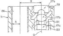
要使突出的处理器具28被摄像单元119拍摄到的必要条件为:如图17所示,在处理器具28移动到最靠摄像单元119侧的情况下,由于摄像单元119的前端透镜面处的光线高Lh=1.2mm、前端开口26的半径R=1.4mm、摄像单元119的视场角θ为例如θ=138°、摄像单元119的光轴O与前端开口26的中心的距离D=6mm,因此作为处理器具28从插入部7的前端部11的前端面突出的最小突出量Hmin,可按下式5导出。The necessary condition for the protrudingtreatment tool 28 to be photographed by thecamera unit 119 is as follows: as shown in FIG. Light height Lh=1.2mm, radius R=1.4mm offront end opening 26, field angle θ ofimaging unit 119 are for example θ=138°, distance D=6mm between optical axis O ofimaging unit 119 and the center offront end opening 26 , therefore, the minimum protrusion amount Hmin of thetreatment tool 28 protruding from the front end surface of thefront end portion 11 of theinsertion portion 7 can be derived fromEquation 5 below.

Hmin=(D-Lh-R)×tan(90°-θ/2)=1.38mm(式5)Hmin=(D-Lh-R)×tan(90°-θ/2)=1.38mm (Formula 5)

另一方面,在处理器具28位于离摄像单元119最远的方向上的情况下,处理器具28突出,要使处理器具28的前端整体被摄像单元119拍摄到的必要条件为:作为处理器具28从插入部7的前端部11的前端面突出的突出量Hall,按下式6导出。On the other hand, when thetreatment tool 28 is located in the direction farthest from theimaging unit 119, thetreatment tool 28 protrudes, and the necessary condition for the entire front end of thetreatment tool 28 to be photographed by theimaging unit 119 is: as thetreatment tool 28 The protrusion amount Hall protruding from the front end surface of thefront end portion 11 of theinsertion portion 7 is derived from Equation 6 below.

Hall=(D-Lh+R)×tan(90°-θ/2)=2.45mm(式6)Hall=(D-Lh+R)×tan(90°-θ/2)=2.45mm (Formula 6)

如式5、式6所示,当处理器具28从前端部11的前端面突出的突出量达到1.38mm以上时开始进入摄像单元119的视野内,突出量为2.45mm时处理器具28的前端的大致整体都进入视野内。As shown inEquation 5 and Equation 6, when the protrusion amount of thetreatment tool 28 from the front end surface of thefront end portion 11 reaches 1.38 mm or more, it begins to enter the field of view of theimaging unit 119. When the protrusion amount is 2.45 mm, the front end of thetreatment tool 28 Almost all of them come into view.

由此,在本实施例中的设定于摄像单元119的近点侧的状态下,景深为5.2mm~10mm,处理器具28的前端侧确实地进入摄像单元119的视野内,可在监视器5上进行识别。Therefore, in the state set on the near point side of theimaging unit 119 in this embodiment, the depth of field is 5.2 mm to 10 mm, and the front end side of thetreatment instrument 28 is surely within the field of view of theimaging unit 119, and can be viewed on the monitor. 5 for identification.

接着参考图18说明通过摄像单元119,在设定于近点侧的状态下拍摄黑白对带子间距为35μm的被拍摄物体等时的作用。Next, the operation when theimaging unit 119 is set to the near-point side to capture an image of a subject with a black-and-white pair-strip pitch of 35 μm will be described with reference to FIG. 18 .

图18表示将本实施例的电子内窥镜2C的插入部7插入体腔内,利用设置于前端部11上的摄像单元119,对体腔内的处理对象部位侧进行拍摄的同时,使处理器具28从前端开口26突出进行处理的情况的概略图。18 shows that theinsertion part 7 of the electronic endoscope 2C of this embodiment is inserted into the body cavity, and thetreatment instrument 28 is moved while taking pictures of the part to be treated in the body cavity by theimaging unit 119 provided on thefront end part 11. A schematic diagram of a case where processing is protruded from thefront end opening 26 .

此时,作为容易进行处理的条件,希望能够对作为处理对象的患部等进行详细观察,同时希望也能够详细地观察从前端开口26突出的处理器具28的前端侧。At this time, as conditions for easy treatment, it is desirable to be able to observe in detail the affected part to be treated, and also to be able to observe in detail the distal end side of thetreatment tool 28 protruding from thedistal opening 26 .

本实施例中,按如下所示来满足这些条件。首先为使说明更明确,如下所示定义亮度对比度G(MTF)。In this embodiment, these conditions are satisfied as follows. First, to clarify the description, the luminance contrast G(MTF) is defined as follows.

在通过物镜系统117在CCD 118受光面上成像相同宽度的黑白带(条纹)的被拍摄物体时,将针对上述白色被拍摄物体的亮度的最大值设为Gmax、将针对上述黑色被拍摄物体的亮度的最小值设为Gmin、将亮度对比度G定义为G=(Gmax-Gmin)/(Gmax+Gmin)。When an object with black and white bands (stripes) of the same width is imaged on theCCD 118 light-receiving surface by theobjective lens system 117, the maximum value of the brightness for the above-mentioned white object to be imaged is set as Gmax, and the maximum value for the brightness of the above-mentioned black object to be imaged is set to The minimum value of brightness is Gmin, and the brightness contrast G is defined as G=(Gmax−Gmin)/(Gmax+Gmin).

在这样定义亮度对比度G的情况下,按如上所述构成的摄像单元119中,设定在近点的状态下,当物距为5.2mm到6.8mm时,在对黑白对带子60的间距为35μm的被拍摄物体进行拍摄时,在CCD受光面上成像的白带和黑带的亮度对比度G为10%以上。In the case of defining the brightness contrast G in this way, in theimaging unit 119 constituted as described above, set at the near point, when the object distance is 5.2 mm to 6.8 mm, the distance between the pair of black andwhite tapes 60 is When photographing an object of 35 μm, the brightness contrast G of the white and black bands imaged on the light-receiving surface of the CCD is more than 10%.

通过上述物镜系统117在CCD 118的受光面上成像的间距为35μm的黑白对带子的被拍摄物体的像中,从白带所成像的像素输出的图像信号与从黑带所成像的像素输出的图像信号之差为大致10%。In the image of the object being photographed of the black-and-white pair of bands with a pitch of 35 μm on the light-receiving surface of theCCD 118 by the above-mentionedobjective lens system 117, the image signal output from the pixel imaged by the white band and the image output by the pixel imaged from the black band The signal difference is approximately 10%.

上述图像信号通过CDS电路44、A/D转换器45、信号转换部46输入图像处理部47,被实施例如适合于监视器5显示的γ处理和去除噪声的低通滤波处理等。The above-mentioned image signal is input to theimage processing unit 47 through theCDS circuit 44, A/D converter 45, andsignal conversion unit 46, and is subjected to, for example, gamma processing suitable for display on themonitor 5 and low-pass filter processing for removing noise.

并且,在将通过上述白色被拍摄物体得到的亮度信号的最大值设为Imax、通过上述黑色被拍摄物体得到的亮度信号的最小值设为Imin、对比度I定义为I=(Imax-Imin)/(Imax+Imin)的情况下,(对上述黑白对带子的间距为35μm的被拍摄物体进行拍摄时)以对比度I为10%以上的方式输出图像信号。由此,摄像单元119拍摄的间距为35μm的黑白对带子在监视器5上可被识别为黑白对带子。这样,当对比度I达到10%以上时,可在容易识别的状态下进行观察。And, when the maximum value of the luminance signal obtained by the above-mentioned white subject is set as Imax, the minimum value of the luminance signal obtained by the above-mentioned black subject is set as Imin, and the contrast I is defined as I=(Imax-Imin)/ In the case of (Imax+Imin), an image signal is output such that the contrast I is 10% or more (when the subject is photographed with a pitch of 35 μm between black and white pairs of tapes). Thus, the black-and-white pair of tapes with a pitch of 35 μm photographed by theimaging unit 119 can be recognized as a black-and-white pair of tapes on themonitor 5 . In this way, when the contrast I reaches 10% or more, observation can be performed in an easily recognizable state.

图18中,将设定在近点侧的状态下的物距6.8mm设为d、在该位置处配置了间距设为35μm的黑白对带子(条纹)60的情况下,由CCD 18进行光电转换,形成从例如信号转换部46输出的视频信号的亮度信号中的对比度I如上所述为10%以上,从而可在监视器5上识别间距为35μm的黑白对带子60。In FIG. 18, when d is the object distance 6.8mm set on the near point side, and black and white paired strips (stripes) 60 with a pitch of 35 μm are arranged at this position, photoelectricity is performed by the CCD 18. Conversion, the contrast I in the luminance signal of the video signal output from thesignal conversion unit 46 is 10% or more as described above, so that the black andwhite pair bands 60 with a pitch of 35 μm can be recognized on themonitor 5 .

图18中,表示出处理器具28从通道的前端开口26突出的状态,在处理器具28的前端进入摄像单元119的视野内之后,进一步向前方突出,从而处理器具28的前端成为可识别35μm间距的黑白对带子60的物距d的状态。该状态下,物距d比式6的Hall大,从式6变为满足如下条件的状态:In FIG. 18 , the state in which thetreatment tool 28 protrudes from thefront opening 26 of the channel is shown. After the front end of thetreatment tool 28 enters the field of view of theimaging unit 119, it further protrudes forward, so that the front end of thetreatment tool 28 becomes recognizable at a pitch of 35 μm. The state of the object distance d of the black andwhite pair tape 60 . In this state, the object distance d is larger than Hall in Equation 6, and the state from Equation 6 satisfies the following conditions:

d≥(D-Lh+R)×tan(90°-θ/2)(式7)d≥(D-Lh+R)×tan(90°-θ/2) (Formula 7)

若将式7改写,则得到:Ifformula 7 is rewritten, we get:

D≤d/tan(90°-θ/2)+Lh-RD≤d/tan(90°-θ/2)+Lh-R

因此,根据本实施例,在使用焦距可变的光学系统的情况下,可非常详细地观察要通过处理器具28进行处理的患部等被拍摄物体,同时也可非常详细地观察在该患部附近突出的处理器具28的前端的状态,处理变得容易。Therefore, according to the present embodiment, in the case of using the variable focal length optical system, it is possible to observe in great detail an object to be photographed such as an affected part to be treated by thetreatment tool 28, and at the same time, it is possible to observe in great detail protruding objects near the affected part. The state of the front end of thetreatment tool 28 makes handling easier.

由于使用焦距可变的光学系统,因此通过将物镜光学系统的焦距切换为远景侧,可把握宽范围下的状态,可顺利地进行处理。Since a variable focal length optical system is used, by switching the focal length of the objective optical system to the distant view side, the state in a wide range can be grasped and processing can be performed smoothly.

本实施例具有如下效果。This embodiment has the following effects.

本实施例中,构成摄像单元119的物镜系统117采用改变焦点位置时视场角几乎不变的可变焦点光学系统,因此与单焦点光学系统相比,从近景侧到远景侧都可得到高分辨率的内窥镜图像。In this embodiment, theobjective lens system 117 constituting theimaging unit 119 adopts a variable focus optical system whose angle of view hardly changes when the focus position is changed. resolution endoscopic images.

当为可在监视器5上识别上述摄像单元119拍摄的35μm间距的黑白对带子的距离时,由于可在监视器5上识别从通道25的前端开口26突出的处理器具28的前端侧,因而可改善使用以往的变焦光学系统的内窥镜来进行扩大观察时视场角变窄的操作性能。例如根据本实施例,可得到如下效果:能够容易地一边进行大肠的凹坑图案这样的被拍摄物体的详细观察,一边利用处理器具28进行处理。When the distance between the black-and-white pairs of tapes with a pitch of 35 μm captured by the above-mentionedimaging unit 119 can be recognized on themonitor 5, since the front end side of thetreatment tool 28 protruding from thefront opening 26 of thechannel 25 can be recognized on themonitor 5, therefore It is possible to improve the operability in which the field of view narrows when the conventional zoom optical system endoscope is used for extended observation. For example, according to the present embodiment, it is possible to obtain an effect that a treatment can be performed with thetreatment tool 28 while easily observing a subject such as a pit pattern of the large intestine in detail.

在设定在近点侧的状态下,可在监视器上识别35μm的间距的黑白对带子的距离为5.2mm到6.8mm,因此本实施例中,当为比该距离更靠跟前侧的物距时,处理器具28的前端侧可进入视野内,通过再向前方侧突出,可成为达到获得最高分辨率的距离的状态。In the state set to the near point side, the distance between black and white pairs of tapes with a pitch of 35 μm can be recognized on the monitor is 5.2 mm to 6.8 mm. When the distance is high, the front end side of thetreatment tool 28 can enter the field of view, and by protruding forward, it can reach the state at which the highest resolution can be obtained.

因此,本实施例中,当为设定在近点侧的状态下的景深内的距离时,处理器具28的前端侧可充分进入视野内,具有能够比较容易地进行处理器具28的操作的效果。Therefore, in this embodiment, when the distance within the depth of field is set on the near point side, the front end side of thetreatment tool 28 can fully enter the field of view, and there is an effect that thetreatment tool 28 can be operated relatively easily. .

此外,即使在设定在远景侧的情况下,也能够保持规定的分辨率,以景深比近景时大的状态得到被拍摄物体像。In addition, even when it is set to the far view side, a predetermined resolution can be maintained, and a subject image can be obtained with a greater depth of field than in the close view.

由于进行自动对焦控制以使得构成物镜系统117的可变焦点光学系统成为对焦状态,因此操作者不需要繁杂的操作,就可从远景到近景进行高分辨率的内窥镜图像的观察。Since the autofocus control is performed so that the variable focus optical system constituting theobjective lens system 117 is brought into focus, the operator can observe a high-resolution endoscopic image from a distant view to a close view without complicated operations.

此外,当插入处理器具28,成为将其前端显示在监视器5上的状态时,控制光源装置3的照明光量以使得处理器具28附近的亮度为最佳,因此容易进行处理。In addition, when thetreatment tool 28 is inserted and its front end is displayed on themonitor 5, the illumination light quantity of thelight source device 3 is controlled so that the brightness near thetreatment tool 28 is optimized, thereby facilitating treatment.

本实施例中,CCD 118的像素间距为2.5μm、有效像素数为130万像素、摄像单元119的最大视场角为138°、近点侧的景深为5.2mm到10mm、摄像单元119的光轴O与前端开口26中心的距离为6mm,但不限定于此。In this embodiment, the pixel pitch of theCCD 118 is 2.5 μm, the number of effective pixels is 1.3 million pixels, the maximum viewing angle of thecamera unit 119 is 138°, the depth of field at the near point side is 5.2 mm to 10 mm, and the light of thecamera unit 119 The distance between the axis O and the center of the front end opening 26 is 6 mm, but is not limited thereto.

例如,对黑白对带子60的间距为35μm的被拍摄物体进行拍摄时,变更像素间距、有效像素数、最大视场角、近点侧的景深等,以使得从拍摄上述白色被拍摄物体而获得的像素得到的输出信号与从拍摄上述黑色被拍摄物体而获得的像素得到的输出信号之差为10%以上,并且在对上述35μm的被拍摄物体进行拍摄时当为使输出信号之差为10%以上的物距时,即使为了能够观察处理器具而变更最大视场角、及摄像单元119的光轴O与前端开口26中心的距离,也可得到大致同样的效果。For example, when photographing a subject with a pitch of 35 μm between the black and white pair oftapes 60, change the pixel pitch, effective number of pixels, maximum angle of view, depth of field on the near point side, etc. so that The difference between the output signal obtained from the pixel and the output signal obtained from the pixel obtained by photographing the above-mentioned black subject is 10% or more, and when the above-mentioned 35 μm subject is photographed, the difference between the output signals is 10% When the object distance is greater than or equal to 100%, substantially the same effect can be obtained even if the maximum viewing angle and the distance between the optical axis O of theimaging unit 119 and the center of thefront opening 26 are changed in order to observe the treatment instrument.

上述说明中,CCD 118的有效像素数为130万像素,但在马赛克滤色器方式的情况下,即便是150万像素左右也可实现同样的效果,此时,具有可进一步增大获得最高分辨率的距离的效果。本实施例中,使用补色系的马赛克滤色器方式的彩色CCD来进行了说明,但不限定于此,电子内窥镜中,有时还采用如下方式:使用切换式等的三原色光作为照明光,与按顺序照射的三原色光同步,利用单色(黑白)CCD取入被拍摄物体像,在图像处理装置中进行彩色化,在这种方式下通过满足上述条件,也可得到同样的效果。In the above description, the effective number of pixels ofCCD 118 is 1.3 million pixels, but in the case of the mosaic color filter method, the same effect can be achieved even with about 1.5 million pixels. The effect of the distance of the rate. In this embodiment, a color CCD of the mosaic color filter method of the complementary color system is used for description, but the invention is not limited to this. In electronic endoscopes, a system may be adopted in which three primary color lights such as a switching type are used as illumination light. Synchronously with the sequentially irradiated three-primary-color light, a monochrome (black-and-white) CCD is used to capture the subject image, and it is colored in the image processing device. In this way, the same effect can also be obtained by satisfying the above conditions.

该方式的情况下,可得到R信号、G信号、B信号作为有效像素数为65万像素左右的CCD输出信号,虽然也可以不生成亮度信号而向监视器5输出,但该情况下,只要将亮度最高的G信号视为亮度信号即可。In the case of this method, the R signal, the G signal, and the B signal can be obtained as CCD output signals with an effective pixel number of about 650,000 pixels. Although it is also possible to output to themonitor 5 without generating a luminance signal, in this case, only The G signal with the highest luminance may be regarded as a luminance signal.

本实施例中,使用致动器作为移动接合透镜117d、改变焦点位置的装置,进行基于自动对焦的焦点位置控制,实现近景侧的非常精细的观察,但不限定于此,例如作为移动接合透镜117d的装置,采用如下手段可得到同样效果:在透镜移动框134上安装线,并将该线安装在设置于操作部8上的操作杆上,通过操作该操作杆可将焦点位置在近景远景之间切换。In this embodiment, the actuator is used as a device for moving the cementedlens 117d to change the focus position, and the focus position control based on autofocus is performed to realize very fine observation on the close-range side. The device of 117d can obtain the same effect by adopting the following means: a line is installed on thelens moving frame 134, and the line is installed on the operating lever arranged on theoperating part 8, and the focus position can be set in the close-range and distant view by operating the operating lever. switch between.

视场角优选是在考虑了周围的观察性的一般的内窥镜中使用的100°以上的视场角,视场角宽的话,则具有处理器具检测距离变短的效果。The angle of view is preferably 100° or more, which is used in general endoscopes in consideration of peripheral visibility, and a wider angle of view has the effect of shortening the detection distance of the treatment instrument.

本实施例的图像处理装置4C和监视器5利用对应于HDTV方式的视频信号来进行了说明,但不限定于此,例如也可使用对应于SVGA、XGA这样的高分辨率监视器的显示方式。The image processing device 4C and monitor 5 of this embodiment have been described using video signals corresponding to the HDTV system, but are not limited to this, and for example, a display system corresponding to a high-resolution monitor such as SVGA or XGA may be used. .

此外,本实施例的摄像单元119中,作为释放CCD 118的热的装置,公开了通过散热部件139和散热用电缆140向插入部7的前端部件散热,但也可以是如下结构:不在散热部件139上设置散热用电缆140,使插入部7的前端部件的导热性好的部分接近与散热部件对置的部分,通过导热性好的密封树脂等散热。In addition, in theimaging unit 119 of the present embodiment, as the device for releasing the heat of theCCD 118, it is disclosed to dissipate heat to the front end part of theinsertion part 7 through theheat dissipation component 139 and theheat dissipation cable 140, but it may also be the following structure: not in the heat dissipation component. 139 is provided with aheat dissipation cable 140, so that the portion with good thermal conductivity of the front end member of theinsertion portion 7 is close to the portion opposite to the heat dissipation component, and heat is dissipated through a sealing resin with good heat conductivity.

作为散热用电缆140,也可使用信号电缆21的一部分。例如信号电缆21内也可设置不用于驱动的虚设电缆(dummy cable),还可使用以信号电缆21的电磁屏蔽为目的的外部屏蔽。并且,不设置散热部件135,在CCD芯片118b附近用导电性好的密封树脂来固定散热用电缆140的导体部分,也可得到同样的散热效果。A part of thesignal cable 21 may also be used as theheat dissipation cable 140 . For example, a dummy cable not used for driving may be provided inside thesignal cable 21, and an external shield for the purpose of electromagnetic shielding of thesignal cable 21 may be used. Furthermore, the same heat dissipation effect can be obtained by fixing the conductor portion of theheat dissipation cable 140 with a highly conductive sealing resin near theCCD chip 118b without providing theheat dissipation member 135 .

在CCD基板118c上配置CCD芯片118b内部的输出级作为外部放大器,将CCD芯片118b的消耗功率分配给外部基板上的部件,由此来抑制CCD芯片118b的发热也是有效的。It is also effective to dispose the output stage inside theCCD chip 118b as an external amplifier on theCCD substrate 118c and distribute the power consumption of theCCD chip 118b to components on the external substrate, thereby suppressing heat generation of theCCD chip 118b.

(实施例4)(Example 4)

接着参考图19到图23说明本发明实施例4。图19表示具有实施例4的电子内窥镜系统1D的整体结构。该电子内窥镜系统1D具有:与图11的电子内窥镜2C的一部分不同的电子内窥镜2D;和具有CPU 71的视频处理器4D,该CPU 71具有两阶段(自动)对焦控制功能71a,来取代实施例3的视频处理器4C的自动对焦部137。光源部3和监视器5与实施例3结构相同。Next, Embodiment 4 of the present invention will be described with reference to FIG. 19 to FIG. 23 . FIG. 19 shows the overall configuration of an electronic endoscope system 1D having a fourth embodiment. This electronic endoscope system 1D has: anelectronic endoscope 2D different from a part of the electronic endoscope 2C of FIG. 11; and avideo processor 4D having aCPU 71 having a two-stage (automatic) focusingcontrol function 71a to replace theautofocus unit 137 of the video processor 4C of the third embodiment. The structure of thelight source unit 3 and themonitor 5 is the same as that of the third embodiment.

本实施例的电子内窥镜2D基本结构与实施例3相同,CCD的有效像素数和物镜系统的一部分结构不同,同时摄像单元和处理器具通道的位置关系不同。下面以不同之处为重点来说明。The basic structure of theelectronic endoscope 2D of this embodiment is the same as that ofEmbodiment 3, but the number of effective pixels of the CCD and a part of the structure of the objective lens system are different, and the positional relationship between the camera unit and the channel of the processing tool is different. The differences are highlighted below.

图20是表示从正面观察本实施例的电子内窥镜2D的插入部7的前端部11的前端面的主视图,图21是沿着图20的D-D线的截面图,图23是处理器具28从前端部11突出时的监视器显示视频。FIG. 20 is a front view showing the front end surface of thefront end portion 11 of theinsertion portion 7 of theelectronic endoscope 2D according to this embodiment, FIG. 21 is a cross-sectional view along line D-D in FIG. 20 , and FIG. 23 is a treatment instrument. The monitor display video when 28 protrudes from thefront end portion 11.

本实施例的电子内窥镜2D的前端部11中采用图20或图21所示的包括物镜系统172和CCD 173的摄像单元119B。The imaging unit 119B including the objective lens system 172 and theCCD 173 shown in FIG. 20 or FIG. 21 is used in thefront end portion 11 of theelectronic endoscope 2D of this embodiment.

该CCD 173采用像素间距为2.8μm、对监视器显示有效的像素数是80万像素的CCD。ThisCCD 173 adopts a CCD with a pixel pitch of 2.8 μm and an effective number of pixels for monitor display of 800,000 pixels.

摄像单元119B具有在例如设定在近点侧(近景)的状态下最大视场角为160°的可变焦点物镜系统172,该物镜系统172的最前端的第一透镜172a采用凹凸形状的透镜。The imaging unit 119B has, for example, a variable focus objective lens system 172 with a maximum field angle of 160° when it is set on the near point side (close view), and the frontmostfirst lens 172a of the objective lens system 172 is a concave-convex lens. .

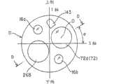
如图20所示,插入部7的前端部11配置有:包括第一透镜172a的外径为φ2.8mm、形状为凹凸形状的物镜系统172的摄像单元119B;通道前端开口26B;去除在物镜系统172的前端表面上因送气送水而造成的附着污物的送气送水喷嘴143;将由光源装置3从传送照明光的光导的前端面射出的光照射向被拍摄物体侧来进行照明的照明透镜16a、16b。As shown in Figure 20, thefront end portion 11 ofinsertion portion 7 is equipped with: the outer diameter that comprisesfirst lens 172a is the imaging unit 119B of the objective lens system 172 of φ 2.8mm, shape is concave-convex shape; Passage front end opening 26B; The air-supply water-supply nozzle 143 on the front-end surface of the system 172 is caused by the air-supply water-supply dirt, and theillumination lens 16a illuminates the subject by irradiating the light emitted by thelight source device 3 from the front end surface of the light guide that transmits the illumination light. , 16b.

摄像单元119B在插入部前端上安装成使得在对被拍摄物体进行拍摄、显示在监视器5上时的监视器5上的上下方向与图20所示的插入部前端的上下方向一致。The imaging unit 119B is attached to the front end of the insertion part such that the vertical direction on themonitor 5 when the subject is photographed and displayed on themonitor 5 coincides with the vertical direction of the front end of the insertion part shown in FIG. 20 .

内径为φ2.8mm的处理器具通道25配置在相对于摄像单元119B从水平方向稍稍偏离的左斜下方的方向上,如图20所示,若设前端部11的上下方向为Y轴、左右方向为X轴,连接处理器具通道25的中心轴与摄像单元119B的光轴O的直线相对于上述X轴成α的角度。Thetreatment instrument channel 25 with an inner diameter of φ2.8 mm is arranged in a direction obliquely below the left and slightly deviated from the horizontal direction relative to the imaging unit 119B, as shown in FIG. is the X-axis, and the straight line connecting the central axis of thetreatment tool channel 25 and the optical axis O of the imaging unit 119B forms an angle α with respect to the above-mentioned X-axis.

如图21所示,物镜系统172的光轴O与前端开口26B平行地配置,本实施例中,物镜系统172的中心(光轴O)与前端开口26B的中心轴的距离D为6mm。As shown in FIG. 21 , the optical axis O of the objective lens system 172 is arranged parallel to the front opening 26B. In this embodiment, the distance D between the center (optical axis O) of the objective lens system 172 and the central axis of the front opening 26B is 6 mm.

本实施例中,图21所示的第一透镜172a、第二透镜172b和第三透镜172c安装在第一透镜框31上,与该第一透镜框31嵌合的CCD框133内与实施例3同样地通过透镜保持框134可自由移动地配置接合透镜117d,接合透镜117d通过致动器129沿光轴O的方向移动。In this embodiment, thefirst lens 172a, the second lens 172b and the third lens 172c shown in FIG. Similarly, the cementedlens 117d is freely movably arranged by thelens holding frame 134, and the cementedlens 117d is moved in the direction of the optical axis O by theactuator 129.

设置在视频处理器4D上的CPU 71不采用实施例3中的基本上连续地进行自动对焦控制的方式,而是进行对焦控制,使接合透镜117d移动,以使得物镜系统172的焦点位置在远景位置和近景位置这2个位置之间成为更接近对焦的状态。即,进行两阶段(通过自动切换的近似)对焦控制。TheCPU 71 provided on thevideo processor 4D does not adopt the method of performing autofocus control basically continuously inEmbodiment 3, but performs focus control to move the cementedlens 117d so that the focus position of the objective lens system 172 is in the distance. The focus is closer between the two positions of the position and the close-range position. That is, two-stage (approximate by automatic switching) focus control is performed.

此时CPU 71从内窥镜ID存储器74读入与视频处理器4D连接的电子内窥镜2D的ID信息,向RAM71c中存储该电子内窥镜2D的摄像单元119B的光学特性信息。该光学特性信息是将接合透镜117d设定在近景时的位置处的情况下、和设定在远景时的位置处的情况下物距改变时的代表性的对比度变化特性或与分辨率有关的信息。At this time, theCPU 71 reads the ID information of theelectronic endoscope 2D connected to thevideo processor 4D from theendoscope ID memory 74, and stores the optical characteristic information of the imaging unit 119B of theelectronic endoscope 2D in theRAM 71c. This optical characteristic information is representative contrast change characteristics or information related to resolution when the object distance changes when the cementedlens 117d is set at a position for a close-up view and a position for a distant view. information.

并且,CPU 71在进行两阶段的对焦控制时,调查在接合透镜117d被设定在实际所设定的一方位置上的状态下对比度信息的时间性的变化等,通过参照存储在RAM 71c中的光学特性信息,判断该变化是否表示切换到另一方位置能获得更大的对比度值,即,判断是否更接近对焦状态。In addition, when theCPU 71 performs two-stage focus control, it investigates temporal changes in the contrast information in a state where the cementedlens 117d is set at a position that is actually set, and the like by referring to the Optical characteristic information, to determine whether the change indicates that a larger contrast value can be obtained by switching to the other position, that is, to determine whether it is closer to the in-focus state.

并且,在CPU 71判断为切换到另一方位置能获得更大的对比度值的情况下,控制致动器驱动部136,将接合透镜117d设定到另一方位置处。And, when theCPU 71 judges that a larger contrast value can be obtained by switching to the other position, it controls theactuator drive unit 136 to set the cementedlens 117d to the other position.

CPU 71在将接合透镜117d设定到另一方位置处的情况下,也随着时间监视该状态下的对比度信息,通过进行同样的动作,控制成位于2个透镜位置中更接近对焦状态的透镜位置。When theCPU 71 sets the cementedlens 117d to the other position, it also monitors the contrast information in this state over time, and by performing the same operation, it controls the lens located closer to the in-focus state among the two lens positions. Location.

此时,CPU 71从来自信号转换部46的亮度信号中检测出亮度信息,再由图像处理部47检测出对比度信息,在规定亮度以上的状态下,如上所述,监视对比度信息的时间性变化,通过参照光学特性信息判断是否应该切换,对应于该判断结果在2个位置上控制接合透镜117d。在得不到规定亮度的情况下和初始状态下,CPU 71进行设定到远景位置的控制。At this time, theCPU 71 detects luminance information from the luminance signal from thesignal conversion unit 46, and then detects the contrast information by theimage processing unit 47, and monitors the temporal change of the contrast information as described above in the state of a predetermined brightness or higher. , by referring to the optical characteristic information to determine whether or not to switch, and to control the cementedlens 117d at two positions according to the determination result. Under the situation that cannot obtain prescribed brightness and under the initial state,CPU 71 carries out the control that is set to the distance position.

本实施例中,在切换设定到近景时和远景时的2个位置上的情况下,两者的状态下的物镜系统172分别表示出不同的光学特性。例如近景时具有最高分辨率,相反远景时分辨率比近景时稍低,但具有比近景时大的景深。具体说,调整Fno使得接合透镜117d设定在近景侧的状态的情况下,景深为4.4mm到12mm,设定在远景侧的状态的情况下景深为9mm到100mm。In the present embodiment, when the switch is set to the two positions of the close-up view and the distant view view, the objective lens system 172 in both states shows different optical characteristics. For example, the close view has the highest resolution, on the contrary, the distant view has a slightly lower resolution than the close view, but has a larger depth of field than the close view. Specifically, Fno is adjusted so that the depth of field is 4.4 mm to 12 mm when the cementedlens 117d is set on the near view side, and 9 mm to 100 mm when the cementedlens 117d is set on the far view side.

并且,两者的特性中的分辨率在近景与远景的中间距离处在表示出大致相反的倾向的状态下有交叉(重叠)部分,因此能够判断该交叉部分中,在从交叉的位置有一定程度的偏移的状态下,将接合透镜117d设定在哪个位置上更接近对焦状态。CPU 71进行该判断,并且根据该判断结果控制接合透镜117d的位置切换。In addition, the resolutions in the characteristics of the two have an intersection (overlap) part in a state showing approximately opposite tendencies at the intermediate distance between the near view and the distant view, so it can be judged that there is a certain difference in the intersection part from the position of the intersection. In the state of shifting to a certain degree, at which position is the cementedlens 117d set closer to the in-focus state. TheCPU 71 makes this judgment, and controls the position switching of the cementedlens 117d according to the judgment result.

本实施例中,设定成使得设定在远景和近景的状态下的物镜系统172的景深在规定值以上的部分中连续(重叠),并且设定成使在达到规定值的空间频率的范围内对比度I也在具有规定值(例如10%)以上的对比度的部分中重叠。In the present embodiment, it is set so that the depth of field of the objective lens system 172 set under the state of the distant view and the close view is continuous (overlapped) in the part above the predetermined value, and is set so that in the range of the spatial frequency reaching the predetermined value The internal contrast I also overlaps in a portion having a contrast of a predetermined value (for example, 10%) or higher.

接着说明本实施例的近景时的作用。Next, the action in the close-up view of this embodiment will be described.

首先,说明通过摄像单元119B在近景时对黑白对带子间距为35μm的被拍摄物体进行拍摄时的作用。First, the operation when the imaging unit 119B captures a subject with a black-and-white pair of tape pitches of 35 μm in a close-up view will be described.

本摄像单元119B中,在设定在近点的状态下,当在物距为4.4mm到5.8mm时对黑白对带子间距为35μm的被拍摄物体进行拍摄时,在CCD受光面上成像的白带和黑带的对比度G为10%以上。In the camera unit 119B, when the object distance is 4.4mm to 5.8mm and the object distance is 4.4mm to 5.8mm, when the object to be photographed is 35μm, the leucorrhea imaged on the light receiving surface of the CCD The contrast G with the black band is 10% or more.

通过上述物镜系统172在CCD 173的受光面上成像的间距为35μm的黑白对带子的被拍摄物体像被光电转换。并且,从白带所成像的像素输出的图像信号与从黑带所成像的像素输出的图像信号之差为10%以上。The black-and-white pairs of strips with a pitch of 35 μm formed on the light-receiving surface of theCCD 173 by the above-mentioned objective lens system 172 are photoelectrically converted. And, the difference between the image signal output from the pixel imaged by the white band and the image signal output by the pixel imaged by the black band is 10% or more.

该图像信号经过CDS电路44、A/D转换器45、信号转换部46输入图像处理部47,被实施例如适合于监视器的γ处理和电掩码处理等,白带与黑带的对比度I为10%以上,输出到监视器5。对上述被拍摄物体的情况,通过使对比度I为10%以上,可以从显示的图像中识别白带和黑带,可在足够的分辨率下进行观察。这样,根据本实施例,由摄像单元119B拍摄的间距为35μm的黑白对带子在监视器上可被识别为黑白对带子。The image signal is input to theimage processing unit 47 through theCDS circuit 44, the A/D converter 45, and thesignal conversion unit 46, and is subjected to, for example, gamma processing and electric mask processing suitable for a monitor. The contrast I of the white band and the black band is More than 10%, output to monitor 5. In the case of the above-mentioned subject, by setting the contrast I to 10% or more, white bands and black bands can be identified from the displayed image, and observation can be performed with sufficient resolution. Thus, according to the present embodiment, the black-and-white paired tapes with a pitch of 35 μm photographed by the imaging unit 119B can be recognized as black-and-white paired tapes on the monitor.

当从近景时开始增大物距时,由于对比度值减小,CPU 71在判断为若进行切换能得到更大的对比度值的情况下,进行将接合透镜117d切换到远景时的位置的控制。When the object distance is increased from the close view, the contrast value decreases, and theCPU 71 performs control to switch the cementedlens 117d to the position of the distant view when it determines that a larger contrast value can be obtained by switching.

通过这样进行切换控制,在从近景向远景改变观察状态的情况下,能够在2个位置中更接近对焦状态的透镜位置的状态下得到内窥镜图像。By performing switching control in this way, when changing the observation state from the close-up to the distant view, an endoscopic image can be obtained at the lens position closer to the in-focus state among the two positions.

图22表示本实施例的两阶段自动对焦控制(更正确的是两阶段大致自动对焦控制)的动作。下面将对焦略记为AF。FIG. 22 shows the operation of the two-stage autofocus control (more precisely, the two-stage approximate autofocus control) of the present embodiment. Focus will be abbreviated as AF below.

该动作开始时,CPU 71在最初的步骤S11中,从内窥镜ID存储器74读入光学特性信息作为初始设定,存储到RAM 71c中。如步骤S12所示,CPU 71根据光学特性信息,将远景位置与近景位置之间的接近AF的状态下的典型的对比度信息、景深信息和分辨率的特性信息设定为AF切换的判断基准。本实施例的物镜系统117设定成在将接合透镜117d设定在远景位置和近景位置上的情况下,各位置上的对焦状态下的景深部分重复。When this operation starts, theCPU 71 reads the optical characteristic information from theendoscope ID memory 74 as an initial setting in the first step S11, and stores it in theRAM 71c. As shown in step S12, theCPU 71 sets typical contrast information, depth of field information, and characteristic information of resolution in a near-AF state between the distant view position and the near view position as the criterion for judging AF switching according to the optical characteristic information. Theobjective lens system 117 of this embodiment is set so that when the cementedlens 117d is set at the distant view position and the close view position, the depth of field in the in-focus state at each position partially overlaps.

并且,接着的步骤S13中CPU 71进行控制处理,以将接合透镜117d设定在远景位置。Then, in the next step S13, theCPU 71 performs control processing to set the cementedlens 117d at the distant view position.

然后在接着的步骤S14中,CPU 71判断当前的亮度信号的亮度水平是否在预先设定的用于判断暗的图像状态的阈值Vth以上。并且判断为上述亮度水平在该阈值Vth以下时返回步骤S13,仍保持在远景位置,反复进行这些处理。即,在即使进行了自动调光的状态下还是不能确保适当的亮度的情况下,保持远景位置的状态。Then in the next step S14, theCPU 71 judges whether the luminance level of the current luminance signal is above the preset threshold value Vth for judging the dark image state. And when it is judged that the brightness level is equal to or lower than the threshold value Vth, the process returns to step S13, and the background position is maintained, and these processes are repeated. That is, when the appropriate brightness cannot be ensured even with the automatic light adjustment being performed, the state of the distant view position is maintained.

当亮度信号的亮度水平在阈值Vth以下时,将接合透镜117d设定在远景位置的理由如下。将电子内窥镜2D的插入部7插入体腔内,从设置在前端部11的前端面上的照明透镜16a、16b射出照明光,对患部等被拍摄物体照明,因此在到被拍摄物体的距离小的情况下,几乎不会发生照明光量不足的情况。因此,当亮度信号的亮度水平在阈值Vth以下时,认为被拍摄物体处于远方。当亮度信号的亮度水平在阈值Vth以下时,由于S/N降低,难以进行精度高的对焦控制。由于这种理由,当亮度信号的亮度水平在阈值Vth以下时,将接合透镜117d设定在远景位置。When the luminance level of the luminance signal is equal to or lower than the threshold value Vth, the reason why the cementedlens 117d is set at the distant view position is as follows. Theinsertion part 7 of theelectronic endoscope 2D is inserted into the body cavity, and the illumination light is emitted from theillumination lenses 16a and 16b provided on the front end surface of thefront end part 11 to illuminate the subject such as the affected part. In a small case, insufficient lighting light will hardly occur. Therefore, when the luminance level of the luminance signal is below the threshold Vth, it is considered that the subject is far away. When the luminance level of the luminance signal is lower than the threshold value Vth, since the S/N is lowered, it is difficult to perform focus control with high precision. For this reason, when the luminance level of the luminance signal is below the threshold value Vth, the cementedlens 117d is set at the distant view position.

另一方面,当判断为亮度信号的亮度水平在阈值Vth以上时,步骤S15中,CPU 71使用判断基准判断当前检测出的对比度值等是否(比近景侧的情况)更接近远景侧的情况。On the other hand, when it is determined that the luminance level of the luminance signal is equal to or greater than the threshold value Vth, in step S15, theCPU 71 uses a determination criterion to determine whether the currently detected contrast value is closer to the far view side (than the near view side).

然后,在满足该条件的情况下,返回步骤S14,反复进行这些处理。不满足步骤S15的条件时,如步骤S16所示,CPU 71进行控制处理,以将接合透镜117d设定在近景位置。And when this condition is satisfied, it returns to step S14, and these processes are repeated. If the condition of step S15 is not satisfied, as shown in step S16, theCPU 71 performs control processing to set the cementedlens 117d at the close-range position.

并且如步骤S17所示,CPU 71判断当前检测出的对比度值是否(比远景侧的情况)更接近近景侧的情况。并且在不满足该条件的情况下,返回步骤S13,进行将接合透镜117d设定在远景位置的处理。And as shown in step S17, theCPU 71 judges whether the currently detected contrast value is closer to the near view side (than the far view side). And when this condition is not satisfied, it returns to step S13, and the process of setting the cementedlens 117d to the distant view position is performed.

另一方面,在满足该条件的情况下,如步骤S18所示,CPU 71判断当前的亮度信号的亮度水平是否在预先设定的用于判断暗的图像状态的阈值Vth以上。并且在判断为亮度信号的亮度水平在该阈值Vth以下时返回步骤S13。相反判断为在该阈值Vth以上时返回步骤S17。On the other hand, when this condition is satisfied, as shown in step S18, theCPU 71 judges whether or not the brightness level of the current brightness signal is greater than or equal to the preset threshold value Vth for judging a dark image state. And when it is determined that the luminance level of the luminance signal is equal to or less than the threshold value Vth, the process returns to step S13. On the contrary, when it is judged to be equal to or greater than the threshold value Vth, the process returns to step S17.

这样通过进行两阶段的AF控制,在从近景到远景改变观察状态的情况下,能够在2个位置中更接近对焦状态的透镜位置的状态下得到内窥镜图像。By performing the two-stage AF control in this way, when changing the observation state from a close-up to a distant view, an endoscopic image can be obtained at the lens position closer to the in-focus state among the two positions.

电掩码处理如图23所示,在监视器5的显示画面内作成高宽比为1∶1.2的八角形的显示区域5b,在该八角形的显示区域5b中显示摄像单元19B拍摄的被拍摄物体。As shown in FIG. 23, the electrical masking process creates anoctagonal display area 5b with an aspect ratio of 1:1.2 in the display screen of themonitor 5, and displays the subject captured by the imaging unit 19B in theoctagonal display area 5b. Shoot the object.

通过上述电掩码处理得到的显示区域5b上的视场角在如图23所示的横长的显示区域的情况下,对角方向的P点成为最大的视场角(θmax)。实施掩码处理以使得物镜系统172的视场角160°与上述最大视场角θmax一致。另一方面,通过掩码处理,监视器画面上视场角最窄的是上下方向,其次窄的是左右方向的视场角。The angle of view on thedisplay region 5b obtained by the above electric masking process is the maximum angle of view (θmax) at point P in the diagonal direction in the case of a horizontally long display region as shown in FIG. 23 . Mask processing is performed so that the angle ofview 160° of the objective lens system 172 coincides with the maximum angle of view θmax described above. On the other hand, through mask processing, the narrowest angle of view on the monitor screen is in the up and down direction, and the next narrowest is in the left and right directions.

为上述最大对角的P点被设定成使连接P点和画面中心的直线与监视器画面上的水平方向所成角度为α,此外,摄像单元119B如图20所示,配置成插入部的前端部11的X轴方向与监视器水平方向一致,因此从配置在相对于X轴成α角度的位置处的处理器具通道25的前端开口26B突出的处理器具28如图23所示,从监视器5上的大致而言水平方向,更严格地说是比水平方向稍稍下侧的左下方的P点附近开始,显示在显示区域5b内。Point P, which is the above-mentioned largest diagonal angle, is set so that the angle formed by the straight line connecting point P and the center of the screen and the horizontal direction on the monitor screen is α. In addition, the imaging unit 119B is arranged as an insertion part as shown in FIG. 20 The X-axis direction of thefront end portion 11 of thefront end portion 11 coincides with the horizontal direction of the monitor. Therefore, as shown in FIG. The roughly horizontal direction on themonitor 5 , more strictly speaking, starting from the vicinity of point P on the lower left slightly below the horizontal direction, is displayed in thedisplay area 5 b.

本实施例中要使从插入部的前端部11的前端开口26B突出的处理器具28被摄像单元119B拍摄到的必要条件为:在处理器具28移动到最靠摄像单元19B侧的情况下,由于摄像单元119B的前端透镜面处的光线高Lh=1.31mm、前端开口26B的半径R=2.8mm、摄像单元119B的视场角θ=160°、摄像单元119B的光轴O与通道25的距离D=6mm,所以作为处理器具28从前端部11的前端面突出的最小突出量Hmin,可按下式8导出。In this embodiment, the necessary condition for making thetreatment tool 28 protruding from the front end opening 26B of thefront end portion 11 of the insertion part to be photographed by the imaging unit 119B is: when thetreatment tool 28 moves to the side closest to the imaging unit 19B, due to The ray height Lh at the front lens surface of the camera unit 119B=1.31mm, the radius R=2.8mm of the front opening 26B, the field angle θ=160° of the camera unit 119B, the distance between the optical axis O of the camera unit 119B and the channel 25 D=6 mm, therefore, the minimum protrusion amount Hmin of thetreatment tool 28 protruding from the front end surface of thefront end portion 11 can be derived fromEquation 8 below.

Hmin=(D-Lh-R)×tan(90°-θ/2)=0.58mm(式8)Hmin=(D-Lh-R)×tan(90°-θ/2)=0.58mm (Formula 8)

另一方面,在处理器具28位于离开摄像单元119B最远的方向上的情况下,处理器具28突出,要使处理器具28的前端整体被摄像单元119B拍摄到的必要条件为:作为处理器具28从前端部11的前端面突出的突出量Hall,可按下式9导出。On the other hand, when thetreatment tool 28 is located in the farthest direction from the imaging unit 119B, thetreatment tool 28 protrudes, and the necessary condition for the entire front end of thetreatment tool 28 to be photographed by the imaging unit 119B is: as thetreatment tool 28 The amount of protrusion Hall protruding from the front end surface of thefront end portion 11 can be derived fromEquation 9 below.

Hall=(D-Lh+R)×tan(90°-θ/2)=1.07mm(式9)Hall=(D-Lh+R)×tan(90°-θ/2)=1.07mm (Formula 9)

如式8、式9所示,当处理器具28从前端部11的前端面突出的突出量为0.58mm以上时处理器具28开始进入摄像单元119B的视野内,当突出量超过1.07mm时处理器具28的前端的大致整体都进入视野内。As shown inFormula 8 andFormula 9, when the protrusion amount of thetreatment tool 28 from the front end surface of thefront end portion 11 is more than 0.58 mm, thetreatment tool 28 begins to enter the field of view of the imaging unit 119B, and when the protrusion exceeds 1.07 mm, the treatment tool Substantially the entirety of the front end of 28 comes into view.

由此,当距离为可在监视器上识别设定在本实施例中的摄像单元119B的近点侧的状态下的35μm间距的黑白对带子的距离4.4mm到5.8mm时,处理器具28的前端侧进入摄像单元119B的视野内,可在监视器5上进行识别。Thus, when the distance is 4.4 mm to 5.8 mm, the distance between the black and white pairs of tapes at a pitch of 35 μm in the state set on the near point side of the imaging unit 119B in this embodiment can be recognized on the monitor, theprocessing tool 28 The front end side enters the field of view of the imaging unit 119B and can be recognized on themonitor 5 .

本实施例具有如下效果。This embodiment has the following effects.

本实施例中,构成摄像单元119B的物镜光学系统采用改变焦距的可变焦点光学系统,因此与单焦点光学系统的情况相比,从近景侧到远景侧都可得到分辨率高的图像。In this embodiment, the objective optical system constituting the imaging unit 119B adopts a variable focus optical system that changes the focal length, so that images with higher resolution can be obtained from the near-view side to the distant-view side compared with the case of a single-focus optical system.

这里,本实施例中,CCD 173的像素间距为2.8μm、有效像素数为80万像素、摄像单元119B的最大视场角为160°、设定在近点侧的状态下的景深为4.4mm到12mm、摄像单元119B的光轴O与前端开口26中心的距离为6mm,但不限定于此。Here, in this embodiment, the pixel pitch of theCCD 173 is 2.8 μm, the number of effective pixels is 800,000 pixels, the maximum field angle of the imaging unit 119B is 160°, and the depth of field is 4.4 mm when it is set on the near point side. The distance between the optical axis O of the imaging unit 119B and the center of thefront opening 26 is 6 mm to 12 mm, but is not limited thereto.

例如,当对黑白对带子的间距为35μm的被拍摄物体拍摄时,变更像素间距、有效像素数、最大视场角、近点侧的景深等,以使得从拍摄上述白色被拍摄物体而获得的像素得到的输出信号与从拍摄上述黑色被拍摄物体而获得的像素得到的输出信号之差为10%以上,并且当在物距为对上述35μm的被拍摄物体拍摄时输出信号之差为10%以上的物距时,为了能够观察处理器具而变更最大视场角、及摄像单元19的光轴O与前端开口26中心的距离,也可得到大致同样的效果。For example, when photographing a subject with a black-and-white pair of tapes at a distance of 35 μm, change the pixel pitch, effective number of pixels, maximum angle of view, depth of field on the near point side, etc. so that the image obtained from photographing the above-mentioned white subject The difference between the output signal obtained by the pixel and the output signal obtained by the pixel obtained by photographing the above-mentioned black subject is 10% or more, and the difference of the output signal is 10% when the object distance is 35 μm when photographing the above-mentioned subject At the above object distance, substantially the same effect can be obtained by changing the maximum viewing angle and the distance between the optical axis O of theimaging unit 19 and the center of thefront opening 26 so that the treatment instrument can be observed.

本实施例中,有效像素数为80万像素,但在马赛克滤色器方式的情况下,即便60万像素左右也可实现同样的效果,此时,近点侧的景深进一步增大,与远点侧的景深之间的深度交叉区域变宽,因此具有能更顺利地进行焦点切换的效果。In this embodiment, the number of effective pixels is 800,000 pixels, but in the case of the mosaic color filter method, the same effect can be achieved even with about 600,000 pixels. The depth crossing area between the depths of field on the point side becomes wider, which has the effect of enabling smoother focus switching.

本实施例中,可采用如下方式:使用切换式等的三原色光作为照明光,与按顺序照射的三原色光同步,利用单色(黑白)CCD取入被拍摄物体,利用图像处理装置进行彩色化,此时,在使用有效像素数为25万像素左右的CCD的情况下,得到与马赛克滤色器方式的60万像素同样的效果。In this embodiment, the following method can be adopted: use the three primary color lights of switching type as the illumination light, synchronize with the three primary color lights irradiated in sequence, use the monochrome (black and white) CCD to capture the object to be photographed, and use the image processing device to perform colorization , At this time, in the case of using a CCD with an effective pixel number of about 250,000 pixels, the same effect as that of the 600,000 pixels of the mosaic color filter method is obtained.

本实施例中,如图23所示,监视器画面5a的显示区域5b为水平方向的显示尺寸比垂直方向(纵向)长的横长型八角形,但不限定于该情况。In this embodiment, as shown in FIG. 23 , thedisplay area 5b of themonitor screen 5a is a horizontally long octagon whose display size in the horizontal direction is longer than that in the vertical direction (vertical direction), but it is not limited to this case.

更一般地,也可以通过把前端开口配置成使其对应于显示区域中的显示区域宽(或大)的方向,使从该前端开口突出的处理器具28显示在显示区域宽的方向上。这里,所谓“显示区域宽的方向”,是指通过电掩码处理等,在画面上显示的观察图像的显示区域的限制比其他方向小的(或没有限制)的方向。More generally, thetreatment tool 28 protruding from the front opening can also be displayed in the direction of the width of the display area by arranging the opening of the front end so as to correspond to the direction of the wide (or large) display area in the display area. Here, the "direction in which the display area is wide" refers to a direction in which the display area of the observed image displayed on the screen is less restricted (or not restricted) than other directions by electrical masking or the like.

作为本实施例的第一变形例,如图24所示,也可以采用能够由CPU 71通过模式切换开关SW1来选择两阶段自动对焦控制功能71a和三阶段自动对焦控制功能71b的方式。As a first modified example of this embodiment, as shown in FIG. 24 , a mode in which the two-stageautofocus control function 71a and the three-stageautofocus control function 71b can be selected by theCPU 71 through the mode switching switch SW1 may also be adopted.

图24所示的电子内窥镜系统1E例如在图19的电子内窥镜系统1D中,CPU 71除了两阶段自动对焦控制功能71a之外,还具有三阶段自动对焦控制功能71b。In theelectronic endoscope system 1E shown in FIG. 24, for example, in the electronic endoscope system 1D in FIG. 19, theCPU 71 has a three-stageautofocus control function 71b in addition to the two-stageautofocus control function 71a.

并且,该CPU 71对应于通过设置在例如电子内窥镜2D的操作部8上的模式切换开关SW1选择的选择信号,按两阶段自动对焦模式或三阶段自动对焦模式进行对焦控制。In addition, theCPU 71 performs focus control in the two-step autofocus mode or the three-step autofocus mode in response to a selection signal selected by the mode switching switch SW1 provided, for example, on theoperation unit 8 of theelectronic endoscope 2D.

本变形例的情况下,内窥镜ID存储器(存储器)74中存储有该电子内窥镜2D固有的光学特性信息。此时,还存储将接合透镜117d设定在除了近点、远点之外设定在近点与远点之间的中间点处的情况下的对比度值等相关的光学特性信息。还存储将接合透镜117d驱动(移动)到中间点的位置的信息。In the case of this modification, the endoscope ID memory (memory) 74 stores optical characteristic information unique to theelectronic endoscope 2D. At this time, optical characteristic information related to a contrast value and the like in a case where the cementedlens 117 d is set at an intermediate point between the near point and the far point other than the near point and the far point is also stored. Information on driving (moving) the cementedlens 117d to the position of the intermediate point is also stored.

并且,视频处理器4D的CPU 71读出该光学特性信息,例如存储在RAM 71c中,进行实施例4的两阶段对焦控制或三阶段对焦控制。And, theCPU 71 of thevideo processor 4D reads out the optical characteristic information, for example, stores it in theRAM 71c, and performs the two-stage focus control or the three-stage focus control of Embodiment 4.

作为进行三阶段对焦控制的优点,由于在近点和远点的两阶段的对焦控制中,在两者的中间位置附近成为两者光学特性的山谷,很难改善例如景深和分辨率以具有更好的特性。As an advantage of performing three-stage focus control, since in the two-stage focus control of the near point and the far point, there is a valley in the optical characteristics of both near the middle position of the two, it is difficult to improve such as depth of field and resolution to have more nice feature.

例如,在近景和远景时,相对于景深在规定值以上连续、并且对比度I在10%以上的情况,在切换到两者的中间点的位置的情况下,能够以比这些条件更大的景深值和对比度I值连续,可实现进一步改善的光学特性。For example, in the case of a close-up view and a distant view, with respect to the case where the depth of field is continuously greater than a predetermined value and the contrast I is greater than or equal to 10%, when switching to a position in the middle of the two, it is possible to obtain a greater depth of field than these conditions. Values and contrast I values are continuous, enabling further improved optical properties.

这样,通过采用将接合透镜117d设定在近点与远点之间的中间点位置处的结构,可进一步增大景深和分辨率,从而简单地实现更好的光学特性。In this way, by adopting a structure in which the cementedlens 117d is set at the position of an intermediate point between the near point and the far point, the depth of field and the resolution can be further increased, thereby simply realizing better optical characteristics.

进行三阶段对焦控制的控制方法类似于两阶段的对焦控制方法。例如,在设定在近点的状态下,CPU 71监视该状态下的对比度信息的时间性变化,判断在该情况下是否要进行近点状态与中间点的切换。A control method for performing three-stage focus control is similar to a two-stage focus control method. For example, in the state set to the near point, theCPU 71 monitors the temporal change of the contrast information in this state, and judges whether to switch between the near point state and the intermediate point in this case.

在设定在中间点的状态下,也监视对比度信息的时间性变化,根据是向近点侧变化还是向远点侧变化,判断是否要切换到近点侧或远点侧。因此,能够通过与实施例4的情况类似的控制,进行三阶段对焦控制。In the state set to the middle point, the temporal change of the contrast information is also monitored, and it is judged whether to switch to the near point side or the far point side according to whether it changes to the near point side or the far point side. Therefore, it is possible to perform three-stage focus control by control similar to the case of Embodiment 4.

图25是表示第二变形例的CPU 71部分。如图25所示,例如CPU 71也可以对应于模式切换开关SW1的模式切换指示信号,进行两阶段自动对焦控制功能71a和两阶段手动控制功能71d。Fig. 25 shows theCPU 71 part of the second modified example. As shown in FIG. 25, for example, theCPU 71 may also perform a two-stageautofocus control function 71a and a two-stagemanual control function 71d in response to the mode switching instruction signal of the mode switching switch SW1.

两阶段自动对焦控制功能71a与实施例4中说明的相同。在通过模式切换开关SW1设定成两阶段手动控制模式的情况下,CPU 71在操作了手动操作开关SW2的近点指示开关的情况下,使接合透镜17d移动到近点侧。The two-stageautofocus control function 71a is the same as that described in Embodiment 4. When the mode switching switch SW1 is set to the two-stage manual control mode, theCPU 71 moves the cemented lens 17d to the near point side when the near point indicating switch of the manual operation switch SW2 is operated.

另一方面,在操作了手动操作开关SW2的远点指示开关的情况下,CPU 71进行控制动作,以将接合透镜117d移动到远点侧。On the other hand, when the far point indicating switch of the manual operation switch SW2 is operated, theCPU 71 performs a control operation to move the cementedlens 117d to the far point side.

这样通过设置模式选择单元,操作者使用电子内窥镜2D进行诊断等的情况下的观察(拍摄)的选择项变多,更容易使用。By providing the mode selection means in this way, the operator can use theelectronic endoscope 2D to have more options for observation (imaging) when performing diagnosis, etc., and it is easier to use.

图25中,说明了两阶段自动对焦控制功能71a和两阶段手动控制功能71d,但除此之外还可进行三阶段自动对焦控制功能71b和三阶段手动控制功能。也可以使用CPU等进行多阶段的自动对焦控制功能和多阶段的手动控制功能。In FIG. 25, the two-stepautofocus control function 71a and the two-stepmanual control function 71d are described, but the three-stepautofocus control function 71b and the three-step manual control function are also available. It is also possible to perform a multi-stage autofocus control function and a multi-stage manual control function using a CPU or the like.

也可使用CPU等,对应于模式切换指示操作,进行连续的自动对焦控制、多阶段的对焦控制和连续或多段的手动控制。It is also possible to use a CPU or the like to perform continuous auto-focus control, multi-stage focus control, and continuous or multi-stage manual control in response to the mode switching instruction operation.

本实施例的图像处理装置4D和监视器5以对应于HDTV方式的视频信号的图像处理装置和监视器进行了说明,但不限定于此,例如也可以是对应于NTSC方式、PAL方式这样的视频信号的图像处理装置和监视器。或者,还可使用VGA方式、SVGA方式的图像处理装置和监视器。Theimage processing device 4D and monitor 5 of the present embodiment have been described as image processing devices and monitors corresponding to HDTV video signals, but are not limited thereto. For example, they may be those corresponding to NTSC or PAL. Image processing devices and monitors for video signals. Alternatively, a VGA-based or SVGA-based image processing device and monitor may also be used.

另外由上述实施例等部分变形、组合等而构成的实施例等也属于本发明。In addition, the embodiment etc. which consist of partial deformation|transformation, combination, etc. of the above-mentioned embodiment etc. also belong to this invention.

可将插入部插入体腔内、对患部等被拍摄物体在近景侧能进行高精细观察的状态下进行拍摄,同时对远景侧也可确保必要的分辨率,即使插入通道内的处理器具的前端侧从通道的前端开口突出的突出量小的状态下也能进入观察视野内,从而可进行详细观察。The insertion part can be inserted into the body cavity, and the object to be photographed, such as the affected part, can be photographed in a state where high-definition observation can be performed on the close-range side, and at the same time, the necessary resolution can be ensured on the distant view side, even if the front end side of the treatment instrument inserted into the channel Even in a state where the amount of protrusion from the front end opening of the channel is small, it can enter the observation field of view, enabling detailed observation.

Claims (27)

Translated fromChinese
1.一种电子内窥镜,其特征在于,该电子内窥镜包括:1. An electronic endoscope, characterized in that the electronic endoscope comprises:插入到被检测体内的插入部;an insertion part inserted into the body to be tested;通道,其设置在上述插入部,处理器具能够插通于该通道内;a channel, which is provided at the above-mentioned insertion part, and the treatment instrument can be inserted into the channel;单焦点的物镜光学系统,其设置在上述插入部的前端部,成像被拍摄物体的光学像;以及A single-focus objective optical system, which is arranged at the front end of the above-mentioned insertion part, and forms an optical image of the object to be photographed; and摄像元件,其受光面配置在上述物镜光学系统成像的位置上,并且该摄像元件对在其受光面上成像的光学像进行光电转换,An imaging element, whose light-receiving surface is arranged on the imaging position of the above-mentioned objective optical system, and the imaging element performs photoelectric conversion on the optical image formed on the light-receiving surface,在通过上述物镜光学系统对相同宽度的黑白带的被拍摄物体拍摄、根据得到的图像信号生成亮度信号的情况下,当将针对上述白带的被拍摄物体的亮度信号的最大值设为Imax、将针对上述黑带的被拍摄物体的亮度信号的最小值设为Imin、将对比度I定义为I=(Imax-Imin)/(Imax+Imin)时,When the subject of the black-and-white band of the same width is photographed by the above-mentioned objective optical system, and a luminance signal is generated based on the obtained image signal, when the maximum value of the luminance signal of the subject of the above-mentioned leucorrhea is set as Imax, When the minimum value of the luminance signal of the object to be photographed for the above-mentioned black band is set as Imin, and the contrast I is defined as I=(Imax-Imin)/(Imax+Imin),在对离上述插入部的前端的距离为50mm的位置处的黑白对带子的间距为0.5mm的被拍摄物体进行拍摄时,输出按上述定义的对比度I为10%以上的图像信号,When the distance from the front end of the insertion part is 50 mm to the object to be photographed at a distance of 0.5 mm between black and white pairs of tapes, an image signal with a contrast I defined above of 10% or more is output,在物距为对上述黑白对带子的间距为35μm的被拍摄物体拍摄时,输出按上述定义的对比度I为10%以上的图像信号的物距的情况下,从上述通道的前端开口突出的处理器具的前端附近的像成像于上述摄像元件的受光面上。The process of protruding from the front opening of the above-mentioned channel when the object distance is such that when the object distance between the above-mentioned black and white pair of tapes is 35 μm, the object distance is output as an image signal with a contrast I of 10% or more as defined above. The image near the front end of the instrument is formed on the light-receiving surface of the imaging element.2.根据权利要求1所述的电子内窥镜,其特征在于,包括上述物镜光学系统和上述摄像元件的摄像装置的视野角在100°以上,上述摄像元件具有对监视器显示有效的像素数为25万像素以上、85万像素以下的马赛克滤色器。2. The electronic endoscope according to claim 1, characterized in that, the viewing angle of the imaging device comprising the above-mentioned objective optical system and the above-mentioned imaging element is more than 100°, and the above-mentioned imaging element has an effective number of pixels displayed on the monitor. It is a mosaic color filter with more than 250,000 pixels and less than 850,000 pixels.3.根据权利要求1所述的电子内窥镜,其特征在于,包括上述物镜光学系统和上述摄像元件的摄像装置的视野角在100°以上,上述摄像元件具有对监视器显示有效的像素数为10万像素以上、35万像素以下的黑白摄像元件。3. The electronic endoscope according to claim 1, characterized in that, the viewing angle of the imaging device comprising the above-mentioned objective optical system and the above-mentioned imaging element is more than 100°, and the above-mentioned imaging element has an effective number of pixels displayed on the monitor. It is a black-and-white image sensor with more than 100,000 pixels and less than 350,000 pixels.4.根据权利要求1所述的电子内窥镜,其特征在于,在设上述物镜光学系统的前端透镜面处的光线高为Lh、上述通道的前端开口的半径为R、上述物镜光学系统的光轴与上述前端开口的中心的距离为D、能够通过上述物镜光学系统在上述摄像元件上成像的视场角为θ、上述处理器具从插入部的前端突出的突出量为Hall的情况下,当设上述物距为d时,满足Hall=(D-Lh+R)×tan(90°-θ/2)≤d。4. electronic endoscope according to claim 1, is characterized in that, the ray height at the front end lens surface place of setting above-mentioned objective lens optical system is Lh, the radius of the front end opening of above-mentioned passage is R, the radius of above-mentioned objective lens optical system When the distance between the optical axis and the center of the above-mentioned front end opening is D, the angle of view that can be imaged on the above-mentioned imaging element by the above-mentioned objective optical system is θ, and the protrusion amount of the above-mentioned treatment tool protruding from the front end of the insertion part is Hall, When the above-mentioned object distance is assumed to be d, Hall=(D-Lh+R)×tan(90°-θ/2)≦d is satisfied.5.一种电子内窥镜系统,其特征在于,该电子内窥镜系统包括:5. An electronic endoscope system, characterized in that the electronic endoscope system comprises:电子内窥镜,该电子内窥镜在所设置的插入部具有:处理器具能够插通于其中的通道;成像被拍摄物体的光学像的单焦点的物镜光学系统;以及受光面设置在上述物镜光学系统成像的位置上、对在上述受光面上成像的光学像进行光电转换的摄像元件;An electronic endoscope, the electronic endoscope has an insertion part provided with: a channel through which a treatment tool can be inserted; a single-focus objective lens optical system for imaging an optical image of an object to be photographed; and a light-receiving surface arranged on the above-mentioned objective lens An imaging element that photoelectrically converts the optical image formed on the above-mentioned light-receiving surface at the imaging position of the optical system;图像处理装置,其将来自上述摄像元件的图像信号转换为用于在监视器上显示的视频信号,an image processing device that converts an image signal from the aforementioned imaging element into a video signal for display on a monitor,在通过上述物镜光学系统对相同宽度的黑白带的被拍摄物体拍摄、根据得到的图像信号由上述图像处理装置生成能够在上述监视器上显示的视频信号的情况下,将针对上述白带的被拍摄物体的亮度信号的最大值设为Imax、将针对上述黑带的被拍摄物体的亮度信号的最小值设为Imin、将对比度I定义为I=(Imax-Imin)/(Imax+Imin)时,When the subject of black and white bands of the same width is photographed by the above-mentioned objective optical system, and the video signal that can be displayed on the above-mentioned monitor is generated by the above-mentioned image processing device according to the obtained image signal, the subject of the above-mentioned leucorrhea will be When the maximum value of the luminance signal of the object is set as Imax, the minimum value of the luminance signal of the subject object for the above-mentioned black band is set as Imin, and the contrast I is defined as I=(Imax-Imin)/(Imax+Imin),当对离上述插入部的前端的距离为50mm的位置处的黑白对带子的间距为0.5mm的被拍摄物体进行拍摄时,输出按上述定义的对比度I为10%以上的图像信号,When the distance from the front end of the above-mentioned insertion part is 50 mm to the object to be photographed at a distance of 0.5 mm between the black and white pairs of tapes, an image signal with a contrast I defined above of 10% or more is output,在物距为对上述黑白对带子的间距为35μm的被拍摄物体拍摄时,输出按上述定义的对比度I为10%以上的图像信号的物距的情况下,从上述通道的前端开口突出的处理器具的前端附近的像显示于上述监视器上。The process of protruding from the front opening of the above-mentioned channel when the object distance is such that when the object distance between the above-mentioned black and white pair of tapes is 35 μm, the object distance is output as an image signal with a contrast I of 10% or more as defined above. An image near the front end of the appliance is displayed on the aforementioned monitor.6.根据权利要求5所述的电子内窥镜系统,其特征在于,上述通道的前端开口配置成与上述监视器上的显示由上述摄像元件所拍摄的光学像的显示区域中显示区域宽的方向对应。6. The electronic endoscope system according to claim 5, wherein the opening at the front end of the channel is arranged to be as wide as the display area on the monitor for displaying the optical image captured by the imaging element. corresponding to the direction.7.根据权利要求5所述的电子内窥镜系统,其特征在于,上述电子内窥镜系统还包括:7. The electronic endoscope system according to claim 5, wherein the above-mentioned electronic endoscope system further comprises:光源,其产生照明上述被拍摄物体的照明光;A light source that generates illumination light for illuminating the subject to be photographed;处理器具检测部,其检测上述处理器具被显示在上述监视器上;a treatment instrument detection unit that detects that the treatment instrument is displayed on the monitor;亮度检测部,其检测上述处理器具附近的亮度;以及a luminance detection section that detects luminance in the vicinity of the treatment tool; and光量调整部,其根据上述亮度检测部的检测结果,调整照射上述被拍摄物体的照明光量。A light quantity adjustment unit that adjusts the illumination light quantity for illuminating the subject based on the detection result of the brightness detection unit.8.根据权利要求5所述的电子内窥镜系统,其特征在于,包括上述物镜光学系统和上述摄像元件的摄像装置的视野角在100°以上,上述摄像元件具有对监视器显示有效的像素数为25万像素以上、85万像素以下的马赛克滤色器。8. The electronic endoscope system according to claim 5, characterized in that, the angle of view of the imaging device comprising the above-mentioned objective optical system and the above-mentioned imaging element is more than 100°, and the above-mentioned imaging element has effective pixels displayed on the monitor Mosaic color filters with more than 250,000 pixels and less than 850,000 pixels.9.根据权利要求5所述的电子内窥镜系统,其特征在于,包括上述物镜光学系统和上述摄像元件的摄像装置的视野角在100°以上,上述摄像元件具有对监视器显示有效的像素数为10万像素以上、35万像素以下的黑白摄像元件。9. The electronic endoscope system according to claim 5, characterized in that, the viewing angle of the imaging device comprising the above-mentioned objective optical system and the above-mentioned imaging element is more than 100°, and the above-mentioned imaging element has effective pixels displayed on the monitor Black-and-white imaging elements with more than 100,000 pixels and less than 350,000 pixels.10.根据权利要求5所述的电子内窥镜系统,其特征在于,在设上述物镜光学系统的前端透镜面处的光线高为Lh、上述通道的前端开口的半径为R、上述物镜光学系统的光轴与上述前端开口的中心的距离为D、能够通过上述物镜光学系统在上述摄像元件上成像的视场角为θ、上述处理器具从插入部的前端突出的突出量为Hall的情况下,当设上述物距为d时,满足Hall=(D-Lh+R)×tan(90°-θ/2)≤d。10. electronic endoscope system according to claim 5, is characterized in that, the ray height at the front end lens surface place of setting above-mentioned objective lens optical system is Lh, the radius of the front end opening of above-mentioned passage is R, above-mentioned objective lens optical system When the distance between the optical axis of the above-mentioned front end opening and the center of the above-mentioned front end opening is D, the angle of view capable of forming an image on the above-mentioned imaging element through the above-mentioned objective optical system is θ, and the protrusion amount of the above-mentioned treatment instrument from the front end of the insertion part is Hall , when the above-mentioned object distance is set as d, Hall=(D-Lh+R)×tan(90°-θ/2)≤d is satisfied.11.一种电子内窥镜,其特征在于,该电子内窥镜包括:11. An electronic endoscope, characterized in that the electronic endoscope comprises:物镜光学系统,其设置在插入到被检测体内的插入部上;an objective optical system provided on an insertion part inserted into a subject;摄像元件,其具有通过上述物镜光学系统成像被拍摄物体的光学像的规定像素数;An imaging element having a predetermined number of pixels for forming an optical image of an object to be photographed through the above-mentioned objective optical system;透镜移动部,根据基于对相同宽度的黑白带的被拍摄物体进行拍摄时得到的图像信号而生成的亮度信号,将针对上述白带的被拍摄物体的亮度信号的最大值设为Imax、将上述黑带的被拍摄物体上的亮度信号的最小值设为Imin、将对比度I定义为I=(Imax-Imin)/(Imax+Imin)时,为了以规定值以上的对比度I在上述物镜光学系统的近点侧捕捉距离上述插入部的前端规定距离的位置处的被拍摄物体,上述透镜移动部移动构成上述物镜光学系统的至少一部分透镜,改变上述物镜光学系统的焦距,以使得景深有一部分重复;以及The lens moving unit, based on the luminance signal generated based on the image signal obtained when the subject with black and white bands of the same width is captured, sets the maximum value of the luminance signal of the subject with the white band as Imax, When the minimum value of the luminance signal on the subject of the band is set as Imin, and the contrast I is defined as I=(Imax-Imin)/(Imax+Imin), in order to use the contrast I above the specified value in the above-mentioned objective optical system The near point side captures the subject at a position at a predetermined distance from the front end of the insertion part, and the lens moving part moves at least a part of the lenses constituting the objective optical system to change the focal length of the objective optical system so that the depth of field is partially repeated; as well as通道,处理器具能够插通于该通道中,并且该通道开口成使得突出规定距离的上述处理器具的前端配置在通过上述透镜移动部、焦距被设定为近点侧时的上述物镜光学系统的视野角内。a channel through which a treatment tool can be inserted, and the channel is opened so that the front end of the treatment tool protruding a predetermined distance is arranged in the objective optical system when the focal length is set to the near point side by the lens moving part within the viewing angle.12.根据权利要求11所述的电子内窥镜,其特征在于,上述透镜移动部能够连续改变构成上述物镜光学系统的至少一个透镜,上述物镜光学系统具有在近点侧能够以10%以上的上述对比度I来捕捉黑白对带子的间距为35μm的被拍摄物体的景深,并且具有在远点侧对离插入部前端的距离为50mm的位置处的黑白对带子的间距为0.5mm的被拍摄物体拍摄时能以10%以上的上述对比度I来捕捉上述被拍摄物体的景深。12. The electronic endoscope according to claim 11, wherein the above-mentioned lens moving part can continuously change at least one lens constituting the above-mentioned objective optical system, and the above-mentioned objective optical system has a lens that can be adjusted by more than 10% on the near point side. Contrast I above to capture the depth of field of a subject with a black-and-white pair of tapes separated by 35 μm, and a subject with a black-and-white pair of tapes separated by 0.5 mm at a distance of 50 mm from the front end of the insertion part on the far point side The depth of field of the object to be photographed can be captured with the above-mentioned contrast I of 10% or more during shooting.13.根据权利要求11所述的电子内窥镜,其特征在于,上述透镜移动部能够将构成上述物镜光学系统的至少一个透镜设定在近点侧和远点侧两个位置上,上述物镜光学系统具有在上述近点侧能够以10%以上的上述对比度I来捕捉黑白对带子的间距为35μm的被拍摄物体的景深,并且具有在上述远点侧对离插入部前端的距离为50mm的位置处的黑白对带子的间距为0.5mm的被拍摄物体拍摄时能以10%以上的上述对比度I来捕捉上述被拍摄物体的景深。13. The electronic endoscope according to claim 11, wherein the lens moving part can set at least one lens constituting the objective optical system at two positions on the near point side and the far point side, and the objective lens The optical system has a depth of field capable of capturing a subject with a distance between black and white pairs of tapes of 35 μm at the above-mentioned near point side with the above-mentioned contrast I of 10% or more, and has a distance of 50 mm from the front end of the insertion part on the above-mentioned far point side. The depth of field of the above-mentioned object can be captured with the above-mentioned contrast I of 10% or more when the distance between the black and white pair of tapes at the position is 0.5 mm.14.根据权利要求13所述的电子内窥镜,其特征在于,上述透镜移动部还能够将构成上述物镜光学系统的至少一个透镜设定在位于上述近点侧与上述远点侧两个位置之间的第三位置上。14. The electronic endoscope according to claim 13, wherein the lens moving unit can also set at least one lens constituting the objective optical system at two positions on the near point side and the far point side. in the third position between.15.根据权利要求11所述的电子内窥镜,其特征在于,在设上述物镜光学系统的前端透镜面处的光线高为Lh、上述通道的前端开口的半径为R、上述物镜光学系统的光轴与上述前端开口的中心的距离为D、能够通过上述物镜光学系统在上述摄像元件上成像的视场角为θ、上述插入部的前端到上述被拍摄物体的距离为d时,满足D≤d/tan(90°-θ/2)+Lh-R。15. electronic endoscope according to claim 11, is characterized in that, the ray height at the front end lens surface place of setting above-mentioned objective lens optical system is Lh, the radius of the front end opening of above-mentioned passage is R, the radius of above-mentioned objective lens optical system When the distance between the optical axis and the center of the above-mentioned front end opening is D, the angle of view that can be imaged on the above-mentioned imaging element by the above-mentioned objective optical system is θ, and the distance from the front end of the above-mentioned insertion part to the above-mentioned subject is d, D is satisfied. ≤d/tan(90°-θ/2)+Lh-R.16.根据权利要求11所述的电子内窥镜,其特征在于,当通过上述透镜移动部使焦点位置为近景时包括上述物镜光学系统和上述摄像元件的摄像装置的视野角在100°以上,上述摄像元件具有对监视器显示有效的像素数为60万像素以上的马赛克滤色器。16. The electronic endoscope according to claim 11, characterized in that, when the focal position is made close-range by the lens moving part, the angle of view of the imaging device comprising the objective optical system and the imaging element is more than 100°, The above-mentioned imaging device has a mosaic color filter whose number of pixels effective for display on a monitor is 600,000 pixels or more.17.根据权利要求11所述的电子内窥镜,其特征在于,当通过上述透镜移动部使焦点位置为近景时包括上述物镜光学系统和上述摄像元件的摄像装置的视野角在100°以上,上述摄像元件具有对监视器显示有效的像素数为25万像素以上的黑白摄像元件。17. The electronic endoscope according to claim 11, characterized in that, when the focal position is made close-range by the lens moving part, the angle of view of the imaging device comprising the objective optical system and the imaging element is more than 100°, The above-mentioned imaging device has a black-and-white imaging device having an effective number of pixels for display on a monitor of 250,000 or more.18.一种电子内窥镜系统,其特征在于,该电子内窥镜系统包括:18. An electronic endoscope system, characterized in that the electronic endoscope system comprises:插入部,其被插入到被检测体内;an insertion part, which is inserted into the body to be tested;物镜光学系统,其设置在上述插入部上;an objective optical system disposed on the insertion portion;摄像元件,通过上述物镜光学系统在上述摄像元件的受光面上成像被拍摄物体的光学像,并且上述摄像元件对该受光面上成像的光学像进行光电转换;An imaging element, imaging an optical image of the subject on the light-receiving surface of the above-mentioned imaging element through the above-mentioned objective optical system, and the above-mentioned imaging element performs photoelectric conversion on the optical image formed on the light-receiving surface;图像处理装置,其将来自上述摄像元件的图像信号转换为用于在监视器上显示的视频信号;an image processing device that converts an image signal from the aforementioned imaging element into a video signal for display on a monitor;透镜移动部,根据基于对相同宽度的黑白带的被拍摄物体拍摄时得到的视频信号而生成的亮度信号,当将对上述白带的被拍摄物体拍摄时得到的亮度信号的最大值设为Imax、将针对上述黑带的被拍摄物体的亮度信号的最小值设为Imin、将对比度I定义为I=(Imax-Imin)/(Imax+Imin)时,为了在上述物镜光学系统的焦距的近点侧以规定值以上的对比度I来捕捉离上述插入部的前端规定距离的位置处的被拍摄物体,上述透镜移动部移动构成上述物镜光学系统的至少一部分透镜,改变上述物镜光学系统的焦距,以使景深有一部分重复;以及The lens moving unit generates a brightness signal based on a video signal obtained when shooting an object with black and white stripes of the same width. When the maximum value of the brightness signal obtained when shooting the object with white stripes is set to Imax, When the minimum value of the luminance signal of the object to be photographed for the above-mentioned black belt is set as Imin, and the contrast I is defined as I=(Imax-Imin)/(Imax+Imin), for the near point of the focal length of the above-mentioned objective optical system To capture the subject at a position at a predetermined distance from the front end of the insertion portion with a contrast ratio I greater than a predetermined value, the lens moving portion moves at least a part of the lenses constituting the objective optical system to change the focal length of the objective optical system to make the depth of field partially repeat; and处理器具插通通道,其开口成使得突出规定距离的处理器具的前端配置在通过上述透镜移动部被设定在近点侧时的物镜光学系统的视野角内。The treatment instrument insertion channel is opened such that the tip of the treatment instrument protruding a predetermined distance is disposed within the viewing angle of the objective optical system when the lens moving unit is set to the near point side.19.根据权利要求18所述的电子内窥镜系统,其特征在于,上述透镜移动部移动构成上述物镜光学系统的至少一个透镜,上述物镜光学系统具有在近点侧能够以10%以上的上述对比度I来捕捉黑白对带子的间距为35μm的被拍摄物体的景深,并且具有在远点侧对离插入部前端的距离为50mm的位置处的黑白对带子的间距为0.5mm的被拍摄物体拍摄时能以10%以上的上述对比度I来捕捉上述被拍摄物体的景深。19. The electronic endoscope system according to claim 18, wherein the above-mentioned lens moving part moves at least one lens constituting the above-mentioned objective optical system, and the above-mentioned objective optical system has the above-mentioned lens that can be adjusted by more than 10% on the near point side. Contrast I to capture the depth of field of a subject with a black-and-white pair of tapes spaced at 35 μm, and have a black-and-white pair of tapes spaced at 0.5 mm on the far point side for a subject at a distance of 50 mm from the front end of the insertion part Sometimes, the depth of field of the above-mentioned object to be photographed can be captured with the above-mentioned contrast I of 10% or more.20.根据权利要求18所述的电子内窥镜系统,其特征在于,上述电子内窥镜系统具有对焦控制部,该对焦控制部根据上述摄像元件的输出信号而生成控制上述透镜移动部的控制信号,将上述物镜光学系统设定成对焦状态。20. The electronic endoscope system according to claim 18, wherein the electronic endoscope system has a focus control unit that generates a control for controlling the lens moving unit based on an output signal of the imaging element. signal to set the above-mentioned objective optical system in a focused state.21.根据权利要求18所述的电子内窥镜系统,其特征在于,当设上述物镜光学系统的前端透镜面处的光线高为Lh、上述处理器具插通通道的前端开口的半径为R、上述物镜光学系统的光轴与上述前端开口的中心的距离为D、通过上述物镜光学系统在上述摄像元件上成像的视场角为θ、上述插入部的前端到上述被拍摄物体的距离为d时,满足D≤d/tan(90°-θ/2)+Lh-R。21. electronic endoscopic system according to claim 18, is characterized in that, when the ray height at the front end lens surface place of above-mentioned objective lens optical system is set as Lh, the radius of the front end opening of above-mentioned treatment tool insertion channel is R, The distance between the optical axis of the above-mentioned objective optical system and the center of the above-mentioned front end opening is D, the angle of field of imaging on the above-mentioned imaging element by the above-mentioned objective optical system is θ, and the distance from the front end of the above-mentioned insertion part to the above-mentioned photographed object is d , satisfy D≤d/tan(90°-θ/2)+Lh-R.22.根据权利要求18所述的电子内窥镜系统,其特征在于,上述通道的前端开口配置成与上述监视器上的显示由上述摄像元件所拍摄的光学像的显示区域中显示区域宽的方向对应。22. The electronic endoscope system according to claim 18, wherein the opening at the front end of the channel is arranged to be as wide as the display area on the monitor for displaying the optical image captured by the imaging element. corresponding to the direction.23.根据权利要求18所述的电子内窥镜系统,其特征在于,当通过上述透镜移动部使焦点位置为近景时包括上述物镜光学系统和上述摄像元件的摄像装置的视野角在100°以上,上述摄像元件具有对监视器显示有效的像素数为60万像素以上的马赛克滤色器。23. The electronic endoscope system according to claim 18, wherein when the focus position is set to a close view by the lens moving part, the angle of view of the imaging device including the objective optical system and the imaging element is 100° or more The above-mentioned imaging element has a mosaic color filter whose number of pixels effective for monitor display is 600,000 pixels or more.24.根据权利要求18所述的电子内窥镜系统,其特征在于,当通过上述透镜移动部使焦点位置为近景时包括上述物镜光学系统和上述摄像元件的摄像装置的视野角在100°以上,上述摄像元件具有对监视器显示有效的像素数为25万像素以上的黑白摄像元件。24. The electronic endoscope system according to claim 18, wherein when the focus position is set to a close view by the lens moving part, the angle of view of the imaging device including the objective optical system and the imaging element is 100° or more The above-mentioned imaging element has a black-and-white imaging element whose number of pixels effective for monitor display is 250,000 pixels or more.25.根据权利要求20所述的电子内窥镜系统,其特征在于,上述对焦控制部在上述摄像元件的输出信号的亮度水平在规定值以下时进行将上述物镜光学系统设定成对焦于远景位置的状态的控制。25. The electronic endoscope system according to claim 20, wherein the focusing control unit sets the objective optical system to focus on the distant view when the brightness level of the output signal of the imaging element is below a predetermined value. Control of the state of the position.26.根据权利要求18所述的电子内窥镜系统,其特征在于,上述电子内窥镜系统具有存储器,该存储器存储与上述物镜光学系统的光学特性有关的信息。26. The electronic endoscope system according to claim 18, wherein the electronic endoscope system has a memory for storing information on optical characteristics of the objective optical system.27.根据权利要求20所述的电子内窥镜系统,其特征在于,上述电子内窥镜系统具有存储器,该存储器存储与上述物镜光学系统的光学特性有关的信息,上述对焦控制部利用上述信息对上述物镜光学系统进行对焦控制。27. The electronic endoscope system according to claim 20, wherein the electronic endoscope system has a memory for storing information related to the optical characteristics of the objective optical system, and the focusing control unit utilizes the information Focus control is performed on the above-mentioned objective optical system.
CNB2005800154009A2004-05-142005-05-13Electronic endoscopeExpired - LifetimeCN100569174C (en)

Applications Claiming Priority (3)

Application NumberPriority DateFiling DateTitle
JP2004145697AJP4377745B2 (en)2004-05-142004-05-14 Electronic endoscope
JP145697/20042004-05-14
JP109094/20052005-04-05

Publications (2)

Publication NumberPublication Date
CN1953697A CN1953697A (en)2007-04-25
CN100569174Ctrue CN100569174C (en)2009-12-16

Family

ID=35470692

Family Applications (1)

Application NumberTitlePriority DateFiling Date
CNB2005800154009AExpired - LifetimeCN100569174C (en)2004-05-142005-05-13Electronic endoscope

Country Status (2)

CountryLink
JP (1)JP4377745B2 (en)
CN (1)CN100569174C (en)

Families Citing this family (20)

* Cited by examiner, † Cited by third party
Publication numberPriority datePublication dateAssigneeTitle
JP2008029597A (en)*2006-07-282008-02-14Olympus CorpEndoscope apparatus
US8641606B2 (en)2008-02-052014-02-04Masaki ICHIHASHIEndoscope apparatus
JP5388765B2 (en)*2009-09-012014-01-15キヤノン株式会社 Fundus camera
JP5346856B2 (en)*2010-03-182013-11-20オリンパス株式会社 ENDOSCOPE SYSTEM, ENDOSCOPE SYSTEM OPERATING METHOD, AND IMAGING DEVICE
JP5698476B2 (en)*2010-08-062015-04-08オリンパス株式会社 ENDOSCOPE SYSTEM, ENDOSCOPE SYSTEM OPERATING METHOD, AND IMAGING DEVICE
CN102411201A (en)*2010-09-252012-04-11医电鼎众股份有限公司Endoscope device
JP5250653B2 (en)*2011-03-302013-07-31富士フイルム株式会社 Endoscopic imaging apparatus and endoscope
JP5988590B2 (en)*2012-01-172016-09-07オリンパス株式会社 Endoscope device
JP5927077B2 (en)*2012-08-072016-05-25オリンパス株式会社 Endoscope system
JP2014068675A (en)*2012-09-272014-04-21Olympus Medical Systems CorpImaging device and endoscope using imaging device
WO2014189091A1 (en)*2013-05-222014-11-27オリンパスメディカルシステムズ株式会社Endoscope
WO2014199980A1 (en)*2013-06-122014-12-18オリンパスメディカルシステムズ株式会社Endoscope system
EP3085295A4 (en)*2013-12-162017-10-04Olympus CorporationEndoscope device
CN104236515B (en)*2014-09-112017-01-18山东省计量科学研究院Field angle automatic measuring device for medical electronic endoscope
US20170296037A1 (en)*2016-04-142017-10-19Olympus CorporationEndoscope apparatus
TWI597042B (en)*2016-06-292017-09-01 Endoscopic with distance measuring function and distance measuring method
CN106308729B (en)*2016-10-132017-11-24成都英赛景泰光电技术有限公司Imaging method, device and capsule medical apparatus for endoscope
US11712149B2 (en)*2018-02-142023-08-01Suzhou Acuvu Medical Technology Co, Ltd.Endoscopy devices and methods of use
WO2020188688A1 (en)*2019-03-182020-09-24オリンパス株式会社Tip end unit of endoscope
CN111583289A (en)*2020-05-152020-08-25西安工业大学 A kind of endoscope resolution identification method

Citations (3)

* Cited by examiner, † Cited by third party
Publication numberPriority datePublication dateAssigneeTitle
JP2000152913A (en)*1998-09-162000-06-06Asahi Optical Co Ltd Electronic endoscope
JP2000330019A (en)*1999-05-202000-11-30Asahi Optical Co Ltd Endoscope objective variable power optical system
CN1373858A (en)*1999-09-082002-10-09奥林巴斯光学工业株式会社Image pickup optical system for endoscope

Patent Citations (3)

* Cited by examiner, † Cited by third party
Publication numberPriority datePublication dateAssigneeTitle
JP2000152913A (en)*1998-09-162000-06-06Asahi Optical Co Ltd Electronic endoscope
JP2000330019A (en)*1999-05-202000-11-30Asahi Optical Co Ltd Endoscope objective variable power optical system
CN1373858A (en)*1999-09-082002-10-09奥林巴斯光学工业株式会社Image pickup optical system for endoscope

Also Published As

Publication numberPublication date
JP4377745B2 (en)2009-12-02
CN1953697A (en)2007-04-25
JP2005323885A (en)2005-11-24

Similar Documents

PublicationPublication DateTitle
KR100911793B1 (en)Electronic endoscope
CN100569174C (en)Electronic endoscope
JP4464858B2 (en) Electronic endoscope
CN103261940B (en) endoscopic device
CN108778091B (en)Endoscope apparatus, image processing method, and recording medium
EP3420880B1 (en)Fluorescence imaging scope with dual mode focusing structures
US8723937B2 (en)Endoscope system, imaging apparatus, and control method
US6080101A (en)Endoscope video camera head which can be autoclaved
US5608451A (en)Endoscope apparatus
JP5385163B2 (en) Endoscope system
US20160270643A1 (en)Endoscope apparatus
JP7585150B2 (en) IMAGING APPARATUS, METHOD FOR EXECUTING PHASE-DIFFERENCE AUTOFOCUS, ENDOSCOPYRIGHT SYSTEM, AND PROGRAM
CN108185977A (en)Electronic endoscope system and the light source for endoscope
US7678045B2 (en)Endoscope optical system
CA2062284C (en)Plant protection device
JP7486331B2 (en) CONTROL DEVICE AND MEDICAL OBSERVATION SYSTEM
US7126101B2 (en)Image pickup device
JP3286011B2 (en) Electronic camera device
JP2541976B2 (en) Light source device for endoscope
JP2020130193A (en)Endoscope system and fluorescence image outputting method
JP2001128931A (en)Lighting system for endoscope
JPH0461841A (en)Electronic endoscope device
JPH04221526A (en)Electronic endoscope device

Legal Events

DateCodeTitleDescription
C06Publication
PB01Publication
C10Entry into substantive examination
SE01Entry into force of request for substantive examination
C14Grant of patent or utility model
GR01Patent grant
C41Transfer of patent application or patent right or utility model
TR01Transfer of patent right

Effective date of registration:20160218

Address after:Tokyo, Japan

Patentee after:OLYMPUS Corp.

Address before:Tokyo, Japan

Patentee before:Olympus Medical Systems Corp.

Patentee before:OLYMPUS Corp.

CX01Expiry of patent term

Granted publication date:20091216


[8]ページ先頭

©2009-2025 Movatter.jp