CN100565856C - Microstructured cooler and use thereof - Google Patents
Microstructured cooler and use thereofDownload PDFInfo
- Publication number
- CN100565856C CN100565856CCNB2006800252504ACN200680025250ACN100565856CCN 100565856 CCN100565856 CCN 100565856CCN B2006800252504 ACNB2006800252504 ACN B2006800252504ACN 200680025250 ACN200680025250 ACN 200680025250ACN 100565856 CCN100565856 CCN 100565856C
- Authority
- CN
- China
- Prior art keywords
- cooler
- substrate
- channel
- width
- cooler according
- Prior art date
- Legal status (The legal status is an assumption and is not a legal conclusion. Google has not performed a legal analysis and makes no representation as to the accuracy of the status listed.)
- Expired - Fee Related
Links
Images


Classifications
- G—PHYSICS
- G06—COMPUTING OR CALCULATING; COUNTING
- G06F—ELECTRIC DIGITAL DATA PROCESSING
- G06F1/00—Details not covered by groups G06F3/00 - G06F13/00 and G06F21/00
- G06F1/16—Constructional details or arrangements
- G06F1/20—Cooling means
- H—ELECTRICITY
- H01—ELECTRIC ELEMENTS
- H01L—SEMICONDUCTOR DEVICES NOT COVERED BY CLASS H10
- H01L23/00—Details of semiconductor or other solid state devices
- H01L23/34—Arrangements for cooling, heating, ventilating or temperature compensation ; Temperature sensing arrangements
- H01L23/46—Arrangements for cooling, heating, ventilating or temperature compensation ; Temperature sensing arrangements involving the transfer of heat by flowing fluids
- H01L23/473—Arrangements for cooling, heating, ventilating or temperature compensation ; Temperature sensing arrangements involving the transfer of heat by flowing fluids by flowing liquids
- F—MECHANICAL ENGINEERING; LIGHTING; HEATING; WEAPONS; BLASTING
- F28—HEAT EXCHANGE IN GENERAL
- F28F—DETAILS OF HEAT-EXCHANGE AND HEAT-TRANSFER APPARATUS, OF GENERAL APPLICATION
- F28F3/00—Plate-like or laminated elements; Assemblies of plate-like or laminated elements
- F28F3/02—Elements or assemblies thereof with means for increasing heat-transfer area, e.g. with fins, with recesses, with corrugations
- F28F3/04—Elements or assemblies thereof with means for increasing heat-transfer area, e.g. with fins, with recesses, with corrugations the means being integral with the element
- F28F3/048—Elements or assemblies thereof with means for increasing heat-transfer area, e.g. with fins, with recesses, with corrugations the means being integral with the element in the form of ribs integral with the element or local variations in thickness of the element, e.g. grooves, microchannels
- F—MECHANICAL ENGINEERING; LIGHTING; HEATING; WEAPONS; BLASTING
- F28—HEAT EXCHANGE IN GENERAL
- F28F—DETAILS OF HEAT-EXCHANGE AND HEAT-TRANSFER APPARATUS, OF GENERAL APPLICATION
- F28F3/00—Plate-like or laminated elements; Assemblies of plate-like or laminated elements
- F28F3/08—Elements constructed for building-up into stacks, e.g. capable of being taken apart for cleaning
- F28F3/086—Elements constructed for building-up into stacks, e.g. capable of being taken apart for cleaning having one or more openings therein forming tubular heat-exchange passages
- F—MECHANICAL ENGINEERING; LIGHTING; HEATING; WEAPONS; BLASTING
- F28—HEAT EXCHANGE IN GENERAL
- F28F—DETAILS OF HEAT-EXCHANGE AND HEAT-TRANSFER APPARATUS, OF GENERAL APPLICATION
- F28F3/00—Plate-like or laminated elements; Assemblies of plate-like or laminated elements
- F28F3/12—Elements constructed in the shape of a hollow panel, e.g. with channels
- H—ELECTRICITY
- H01—ELECTRIC ELEMENTS
- H01L—SEMICONDUCTOR DEVICES NOT COVERED BY CLASS H10
- H01L2924/00—Indexing scheme for arrangements or methods for connecting or disconnecting semiconductor or solid-state bodies as covered by H01L24/00
- H01L2924/0001—Technical content checked by a classifier
- H01L2924/0002—Not covered by any one of groups H01L24/00, H01L24/00 and H01L2224/00
Landscapes
- Engineering & Computer Science (AREA)
- Physics & Mathematics (AREA)
- General Physics & Mathematics (AREA)
- Microelectronics & Electronic Packaging (AREA)
- General Engineering & Computer Science (AREA)
- Condensed Matter Physics & Semiconductors (AREA)
- Computer Hardware Design (AREA)
- Power Engineering (AREA)
- Theoretical Computer Science (AREA)
- Thermal Sciences (AREA)
- Mechanical Engineering (AREA)
- Human Computer Interaction (AREA)
- Cooling Or The Like Of Semiconductors Or Solid State Devices (AREA)
- Cooling Or The Like Of Electrical Apparatus (AREA)
- Physical Or Chemical Processes And Apparatus (AREA)
- Devices That Are Associated With Refrigeration Equipment (AREA)
Abstract
Description
Translated fromChinese技术领域technical field
本发明涉及一种用于被冷却物体的微结构化的冷却器,以及使用这种冷却器以冷却电子器件例如处理器、更具体地是中央处理器(CPU)以及功率电子器件。The present invention relates to a microstructured cooler for an object to be cooled and the use of such a cooler to cool electronic devices such as processors, more particularly central processing units (CPUs) and power electronics.
背景技术Background technique
电子器件性能的日益提高,例如微处理器时钟频率的增大,也造成这些器件热量累积增大。器件的小型化甚至还增强这种累积。尽管采取了减小处理器功率损耗的措施,但热问题仍增大。而且,一般增大例如服务器的系统内各种器件的封装密度导致需要从变得更小的空间中散失更多的热量。但是,电子器件的性能和耐用性取决于工作温度的最大值及其波动范围。这导致需要使用高性能紧凑冷却系统,以便保证有效的局部散热。The increasing performance of electronic devices, such as increases in the clock frequency of microprocessors, has also resulted in an increase in the accumulation of heat in these devices. The miniaturization of devices even enhances this accumulation. Despite the measures taken to reduce processor power consumption, thermal problems continued to grow. Also, generally increasing the packing density of various devices within systems such as servers results in the need to dissipate more heat from ever smaller spaces. However, the performance and durability of electronic devices depends on the maximum operating temperature and its fluctuation range. This leads to the need to use a high-performance compact cooling system in order to ensure effective local heat dissipation.
当前,现代处理器在1cm2面积上释放出例如150W的热量。这远大于厨灶燃烧器产生的热量(约10W/cm2)。为了散发这部分热量,所用的最重要的冷却系统是热沉、与热沉组合的风扇、热管、Peltier阵列和流体冷却系统。可以预计,将来散发的热量将进一步增大。Currently, modern processors dissipate, for example, 150W of heat over an area of 1 cm2 . This is much greater than the heat produced by a kitchen stove burner (approximately 10W/cm2 ). To dissipate this part of the heat, the most important cooling systems used are heat sinks, fans combined with heat sinks, heat pipes, Peltier arrays and fluid cooling systems. It can be expected that the amount of heat emitted will further increase in the future.
当前,电子器件使用最频繁的冷却技术是环境空气冷却。在很多应用中,这项技术是简单而经济的。对于需要较高冷却性能的系统,这种方法是非常不经济的,因为这需要具有相当高输出的空调系统,这不但导致投资和运行成本大增,而且在能量和环境政策方面也存在问题。Currently, the most frequently used cooling technique for electronic devices is ambient air cooling. In many applications, this technique is simple and economical. For systems that require high cooling performance, this method is very uneconomical because it requires an air conditioning system with a rather high output, which not only leads to a large increase in investment and operating costs, but also poses problems in terms of energy and environmental policies.
随着热输出很高的新一代处理器的产生,空气冷却也达到其极限。在大多数情况下,通过增大风扇输出仍能保证散发热量,但这也增大工作噪音。目前,在商业和家庭应用中,55dB已经是太高了。With the new generation of processors with very high heat output, air cooling is reaching its limits. In most cases, the heat can still be dissipated by increasing the fan output, but this also increases the operating noise. Currently, 55dB is too high for commercial and domestic applications.
与其它冷却系统直接相比,由金属或陶瓷材料制成的流体冷却系统提供最高的冷却输出。这主要是由于例如水的冷却介质的高热容、以及其低粘度。最近,由铜、铝和陶瓷制成的微处理器的水冷却器已经开始在市场上销售。目前,所有这些产品的特征是非工业化的、小规模生产的高制造成本。Fluid cooling systems made of metal or ceramic materials provide the highest cooling output when compared directly to other cooling systems. This is mainly due to the high heat capacity of the cooling medium, such as water, and its low viscosity. Recently, water coolers for microprocessors made of copper, aluminum, and ceramics have become commercially available. Currently, all these products are characterized by high manufacturing costs for non-industrial, small-scale production.
用于IBM功率芯片的液体冷却器公开在:《热传递工程》,25(3),3-12,2004。此冷却器具有小通道结构,但是,它完全由硅制成并直接结合在CPU上。A liquid cooler for IBM power chips is disclosed in: "Heat Transfer Engineering", 25(3), 3-12, 2004. This cooler has a small channel structure, however, it's made entirely of silicon and bonded directly to the CPU.
WO 98/41076 A2描述一种冷却电子器件的设备,其能力通过热沉比公知的冷却器明显增大,并且其导热系数、以及由此得到的总导热性明显提高。该文献在其内容中披露,冷却剂液体在其经过微结构化的热沉时产生的最大压强损失出现在分配结构区和连接通道区。为了解决这个问题,提出提供一种具有多个单层并包括至少一个板的冷却器,所述板具有大量微通道和一个分配通道,并且还具有带连接通道的中间板,以及带收集通道的收集板,当这些板被提供公共的盖板和底板时形成封闭的冷却通道。冷却通道的冷却介质通过入口进入微结构化的热沉,并通过出口从其中流出。冷却介质的中间板形成台阶状和/或斜边的过渡结构,由此使垂直截面相对经过所有各个层的表面表示的入口和/或出口的截面积与微通道的截面积连续融合在一起。作为例子,提到了具有流动截面为0.3×10mm的冷却通道的冷却器。在此冷却器中,实现了8.5W/cm2.K的导热系数以及500ml/min的体积流速下0.5bar的压强损失。在这些功率数据下,这种相当复杂的冷却器仅仅达到一般CPU所需的冷却能力的10%。WO 98/41076 A2 describes a device for cooling electronic components, the capacity of which is significantly increased by means of heat sinks compared to known coolers, and the thermal conductivity, and thus the overall thermal conductivity, is significantly increased. This document discloses in its content that the greatest pressure loss of the coolant liquid as it passes through the microstructured heat sink occurs in the area of the distribution structure and the connecting channels. In order to solve this problem, it is proposed to provide a cooler with several monolayers and comprising at least one plate with a large number of microchannels and a distribution channel, and also with an intermediate plate with connecting channels, and a Collector plates, forming closed cooling channels when these plates are provided with a common cover and base plate. The cooling medium of the cooling channel enters the microstructured heat sink through the inlet and flows out there through the outlet. The intermediate plate of the cooling medium forms a stepped and/or beveled transition structure, whereby the cross-sectional area of the inlet and/or outlet represented by the vertical section relative to the surface passing through all the individual layers is continuously merged with the cross-sectional area of the microchannel. As an example, coolers with cooling channels with a flow cross-section of 0.3×10 mm are mentioned. In this cooler, a thermal conductivity of 8.5 W/cm2 .K and a pressure loss of 0.5 bar at a volumetric flow rate of 500 ml/min were achieved. At these power figures, this rather complex cooler achieves only 10% of the cooling capacity required by typical CPUs.
与已经在研究和开发项目中使用的以及在现有工业技术工艺中使用的微反应器和微热交换器相比,设计电子冷却器的问题仍然远未解决,因为在微反应器或微热交换器中的“热管理”与从表面散发热量的冷却器明显不同。Compared to microreactors and microheat exchangers already used in research and development projects and in existing industrial technological processes, the problem of designing electronic coolers is still far from being solved, because in microreactors or microthermal The "thermal management" in an exchanger is significantly different than a cooler that radiates heat from a surface.
在反应器中,如果想要尽可能接近理想的等温过程,则必须尽可能快地散发或交换流动介质即反应器内产生的热量。基于此原因,需要努力使通道的截面以及通道之间的壁厚在反应过程的技术极限内尽可能低。实际上,反应器在其设计方面也必须优化,例如在流阻、流速等方面。但基本的热管理原理相当简单。In a reactor, if one wants to get as close as possible to an ideal isothermal process, the heat generated in the flowing medium, the reactor, must be dissipated or exchanged as quickly as possible. For this reason, efforts are made to keep the cross-section of the channels and the wall thickness between the channels as low as possible within the technical limits of the reaction process. In fact, the reactor also has to be optimized in terms of its design, eg in terms of flow resistance, flow rate, etc. But the basic thermal management principles are fairly simple.
最近的测试表明,此目的,即从局部强烈加热的表面散发热量是非常复杂的问题。遇到的困难是实际热源位于冷却器外面。因此,液体循环通过的热沉的三维结构内的热阻必须更多地予以考虑。Recent tests have shown that this purpose, ie dissipating heat from locally intensely heated surfaces, is a very complex problem. The difficulty encountered is that the actual heat source is located outside the cooler. Therefore, the thermal resistance within the three-dimensional structure of the heat sink through which the liquid circulates must be more considered.
电子领域的进一步特殊要求(例如冷却CPU器件)使找到此问题的答案更加困难,因为需要以最少的冷却水和冷却器的最小压强损失散发热量。已经发现,甚至使用更加细小的结构即更小的通道截面,也仅能在有限程度上增大冷却能力,因为这使流阻过多增大。Further special requirements in the electronics field (such as cooling the CPU device) make finding an answer to this question even more difficult, since the heat needs to be dissipated with minimal cooling water and minimal pressure loss from the cooler. It has been found that even the use of a finer structure, ie smaller channel cross-sections, can only increase the cooling capacity to a limited extent, since this increases the flow resistance too much.
当需要通过小的表面积散发大量的热量而不允许流阻增大太多时,此效应将成为一个问题。在这种情况下,通过利用增大压差简单地增大冷却介质流动速度不能像预期的一样增大冷却能力。为了应用于PC、服务器和工作站,通常使用低压泵,例如产生的压力达到250mbar。在例如5bar或更大的增大前级压力下运行的当前微反应器的高性能冷却剂泵送系统由于成本原因这里不能接受。This effect becomes a problem when a large amount of heat needs to be dissipated through a small surface area without allowing the flow resistance to increase too much. In this case, simply increasing the cooling medium flow velocity by increasing the differential pressure cannot increase the cooling capacity as expected. For applications in PCs, servers and workstations, low-pressure pumps are commonly used, generating pressures of up to 250 mbar, for example. High performance coolant pumping systems of current microreactors operating at increased backing pressures of
另外的需求是,冷却器需要具有适于电子器件形状的形状,即冷却器的表面积和器件上的安装表面积需要具有相同尺寸。An additional requirement is that the cooler needs to have a shape adapted to the shape of the electronic device, ie the surface area of the cooler and the mounting surface area on the device need to be of the same size.
最后,为了大规模应用,必须使液体冷却器和冷却系统的制造成本不明显高于空气冷却。Finally, for large-scale application, it is imperative that liquid coolers and cooling systems are not significantly more expensive to manufacture than air cooling.
为了解决上述问题,WO 04/032231A首次披露了构造、设计和配置微结构化的冷却器的规则。In order to solve the above problems, WO 04/032231A discloses for the first time the rules for constructing, designing and configuring microstructured coolers.
这里描述的冷却器包括至少两个金属箔和一个基板的堆叠,基板通过热接触面与被冷却物体热接触。金属箔和基板通过适合的结合技术以材料配合的方式连接在一起,优选地通过焊接。在金属箔中存在冷却剂流动通道,通过使冷却剂流过其中散发热量。金属箔中的通道的宽度从100到2000μm,优选地从200到500μm。测试表明,在所有其它参数保持相同的情况下,当通道宽度等于和大于800μm时冷却能力大大下降,对于高性能应用不再具有优势。通道深度从25到1000μm,优选地从50到400μm。优选地,通道宽度和通道深度这两个几何变量的至少一个处于微米范围,并且是水力直径4A/U,A=横截面表面积,U=周长(定义依据:Technische Stronum g slehre(Technical Fluid Dynamics),Kamprath-Reihe,Vogel Verlag,W.Bohl,11.Ed.Page 131;Incropera,Frank P.and Dewitt,David P.:”Fundamentals of Heat and MassTransfer”,4th Edition,John Wiley & Sons,NY,1996,page 449),优选地应该在200到500μm范围内。金属箔中通道之间的平均间距从50到1000μm,优选地从150到300μm。此外,如果通道的截面是矩形的或者接近矩形,从而在箔的通道之间形成腹部,则此间距称为“腹部宽度”。并且,在通道底部的剩余箔厚度从50到300μm,优选地从80到120μm。冷却器的基板的厚度从200到2000μm,优选地从500到1500μm。特别是,如果需要非常高的功率密度,当所有上述参数处于优选范围内时则它们在特定程度上满足这些要求。此外,特别当使用铜作为基板材料时,使用上述参数的范围。The cooler described here comprises a stack of at least two metal foils and a substrate which is in thermal contact with the object to be cooled via a thermal contact surface. Metal foil and substrate are joined together in a material-fit manner by suitable bonding techniques, preferably by welding. There are coolant flow channels in the metal foil through which heat is dissipated by passing the coolant. The width of the channels in the metal foil is from 100 to 2000 μm, preferably from 200 to 500 μm. Tests have shown that, with all other parameters kept the same, the cooling capacity is greatly reduced when the channel width is equal to and greater than 800 μm, which is no longer advantageous for high-performance applications. The channel depth is from 25 to 1000 μm, preferably from 50 to 400 μm. Preferably, at least one of the two geometric variables channel width and channel depth is in the micrometer range and is the hydraulic diameter 4A/U, A = cross-sectional surface area, U = circumference (defined according to: Technische Stronum g slehre (Technical Fluid Dynamics ), Kamprath-Reihe, Vogel Verlag, W. Bohl, 11. Ed. Page 131; Incropera, Frank P. and Dewitt, David P.: "Fundamentals of Heat and Mass Transfer",4th Edition, John Wiley & Sons, NY , 1996, page 449), should preferably be in the range of 200 to 500 μm. The average spacing between channels in the metal foil is from 50 to 1000 μm, preferably from 150 to 300 μm. Furthermore, if the cross-section of the channels is rectangular or nearly so, forming a web between the channels of the foil, this spacing is referred to as the "web width". And, the remaining foil thickness at the channel bottom is from 50 to 300 μm, preferably from 80 to 120 μm. The thickness of the base plate of the cooler is from 200 to 2000 μm, preferably from 500 to 1500 μm. In particular, if very high power densities are required, all the aforementioned parameters fulfill these requirements to a certain extent when they are within the preferred range. Furthermore, especially when copper is used as substrate material, the ranges for the above parameters are used.
在WO 04/032231A给出的一个设计变体中,金属箔大致在热接触面的高度上被至少一个间隙状的分隔室分开,从而所述间隙将金属箔分开。这种结构使从顶部流入分隔室的冷却剂大致在中心区域接触基板,而热接触面处于此中心区。在一个末端,所有通道与间隙连通。结果形成两组平行定向的通道。此外,在另一端与所有通道连通的两个收集室例如处于冷却器内。收集室的优选连通方式是使分隔室的冷却剂流入相交的流动通道并由此流入连通的收集室。In a design variant given by WO 04/032231 A, the metal foils are separated approximately at the level of the thermal contact surface by at least one gap-shaped compartment, so that the gap separates the metal foils. This structure allows the coolant flowing into the compartment from the top to contact the substrate approximately in the central area, and the thermal contact surface is located in this central area. At one end, all channels communicate with the gap. The result is two sets of parallel oriented channels. Furthermore, the two collection chambers communicating with all the channels at the other end are for example inside the cooler. The preferred communication of the collection chambers is for the coolant of the compartments to flow into intersecting flow channels and from there into the communicating collection chambers.
但是,此设计在几何特性方面受到加工方法的限制。通道宽度、通道深度和通道间距(腹部宽度)的下限范围主要是由对制造工艺的当前要求提出的。如果这些几何参数选择的数值非常小,就难以大规模制造冷却器,因为在这种情况下不再可能观察到所需公差。制造可能性取决于所需的技术,从而如果制造技术提高,则下限范围可能更低。However, this design is limited by the machining method in terms of geometric properties. The lower limit ranges for channel width, channel depth and channel pitch (web width) are primarily dictated by current requirements on the manufacturing process. If very small values are chosen for these geometric parameters, it becomes difficult to manufacture coolers on a large scale, since in this case it is no longer possible to observe the required tolerances. The manufacturing possibilities depend on the technology required, so if the manufacturing technology improves, the lower range may be lower.
但目前对提高冷却能力的需求比通过减小范围极限增大冷却器能力的生产可能性增长更快。But the need for increased cooling capacity is currently growing faster than the production possibilities of increasing cooler capacity by reducing the range limit.
发明内容Contents of the invention
因此,本发明的一个目的是提供一种冷却物体的微结构化的冷却器,在保持大规模生产可能性的同时进一步优化其冷却能力。It is therefore an object of the present invention to provide a microstructured cooler for cooling objects whose cooling capacity is further optimized while maintaining the possibility of mass production.
本发明的另一个目的是提供一种微结构化的冷却器,使最少冷却水流过和/或在冷却器中产生的压强损失最小,从而与传统冷却器相比,在冷却剂流过冷却器时流阻不会增大太多。Another object of the present invention is to provide a microstructured cooler that minimizes cooling water flow and/or pressure loss in the cooler, thereby reducing the cooling time when the coolant flows through the cooler compared to conventional coolers. The flow resistance will not increase too much.
本发明的再一个目的是提供一种微结构化的冷却器,其制造成本与传统冷却器相当或甚至低于传统冷却器。Yet another object of the present invention is to provide a microstructured cooler whose manufacturing cost is comparable or even lower than conventional coolers.
本发明的再一个目的是提供一种微结构化的冷却器,其形状适合被冷却的电子器件。Yet another object of the present invention is to provide a microstructured cooler shaped to suit the electronic device being cooled.
这些目的的解决方案是通过权利要求1所述的微结构化的冷却器、以及通过使用权利要求33所述的微结构化的冷却器实现。本发明的优选实施例在从属权利要求中描述。The solution of these objects is achieved by a microstructured cooler as claimed in
本发明涉及一种通过导热接触冷却物体的微结构化的冷却器。本发明更具体地涉及使用这种冷却器冷却诸如处理器(例如中央处理器)和功率电子器件等电子器件。在构造/设计、结构和结合方法方面,本发明的微结构化的冷却器适于大规模制造,从而使微结构化的冷却器的低成本大规模制造成为可能。The present invention relates to a microstructured cooler for cooling objects by thermally conductive contact. The invention more particularly relates to the use of such coolers to cool electronic devices such as processors (eg central processing units) and power electronics. In terms of construction/design, structure and bonding method, the microstructured cooler of the present invention is suitable for mass production, thereby enabling low-cost mass production of the microstructured cooler.
本发明的冷却器包括至少两个金属箔(金属板)和一个基板的堆叠,基板通过热接触面(限于被冷却的物体与冷却器接触的区域)与被冷却物体热接触。金属箔和基板通过适合的结合技术优选地通过焊接/钎焊结合在一起,从而形成材料的单一件。在金属箔中存在冷却剂流动通道,诸如水的冷却剂流过其中以散发热量。优选地,金属箔中的通道彼此平行。The cooler of the invention comprises a stack of at least two metal foils (metal plates) and a base plate in thermal contact with the object to be cooled via a thermal contact surface (limited to the area where the object to be cooled is in contact with the cooler). The metal foil and the substrate are bonded together by suitable bonding techniques, preferably by welding/soldering, so as to form a single piece of material. There are coolant flow channels in the metal foil through which coolant such as water flows to dissipate heat. Preferably, the channels in the metal foil are parallel to each other.
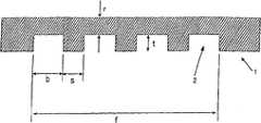
与WO 04/032231A相比,并且根据本发明,为通道宽度b、通道深度t和通道间距(腹部宽度)s(对于这些和其它参数的定义,请参阅图1)选择特定范围。这些参数的实现可以使冷却器得到有利的性能。Compared to WO 04/032231A, and according to the present invention, specific ranges are chosen for channel width b, channel depth t and channel spacing (abdomen width) s (for the definition of these and other parameters see Figure 1). The realization of these parameters can lead to favorable performance of the cooler.
金属箔中通道的宽度b从100到350μm,优选地从200到300μm。测试表明,在所有其它参数保持相同时,冷却器的冷却能力在通道宽度等于和大于350μm时极剧下降,对于高性能应用不再有优势。The width b of the channels in the metal foil is from 100 to 350 μm, preferably from 200 to 300 μm. Tests have shown that when all other parameters remain the same, the cooling capacity of the cooler drops dramatically when the channel width is equal to and greater than 350 μm, which is no longer advantageous for high-performance applications.
通道深度t从30到150μm,优选地从50到120μm。The channel depth t is from 30 to 150 μm, preferably from 50 to 120 μm.
水力直径(定义如上所述)优选地从70到250μm。The hydraulic diameter (defined above) is preferably from 70 to 250 μm.
通道之间的平均间距从30到300μm,优选地从150到300μm。通道之间的间隔称为“腹部”,通道之间的平均间距也称为“腹部宽度”。The average spacing between channels is from 30 to 300 μm, preferably from 150 to 300 μm. The spacing between channels is called "belly", and the average spacing between channels is also called "belly width".
此外,在通道底部的残余箔厚度从30到300μm,优选地从50到250μm,更优选地从50到120μm。Furthermore, the residual foil thickness at the channel bottom is from 30 to 300 μm, preferably from 50 to 250 μm, more preferably from 50 to 120 μm.
冷却器的基板厚度从100到1000μm,优选地从300到500μm。The substrate thickness of the cooler is from 100 to 1000 μm, preferably from 300 to 500 μm.
对于所有上述参数,如果数值处于优选范围,特别是如果所需功率密度特别高时,将在特定程度上达到上述目的。此外,如果使用铜作为金属箔和基板的基本材料,则特别地适应参数的上述范围,但如果使用其它材料也是有效的。For all the abovementioned parameters, the above objects will be achieved to a certain extent if the values are in the preferred ranges, especially if the desired power density is particularly high. Furthermore, the above-mentioned ranges of parameters are especially adapted if copper is used as the basic material of the metal foil and substrate, but are also valid if other materials are used.
对于通道宽度b、通道间距s和残余箔厚度r的最有利组合的选择,使用参数之间的以下优选比例:For the selection of the most favorable combination of channel width b, channel spacing s and residual foil thickness r, the following preferred ratios between the parameters are used:
通道宽度b与通道之间平均间距s之比从1.5∶1到2.5∶1,优选地从1.0∶1到2.0∶1。The ratio of the channel width b to the average spacing s between the channels is from 1.5:1 to 2.5:1, preferably from 1.0:1 to 2.0:1.
通道宽度b与残余箔厚度r之比从1∶1到5∶1,优选地从2∶1到5∶1。The ratio of channel width b to residual foil thickness r is from 1:1 to 5:1, preferably from 2:1 to 5:1.
另一影响变量是通道的纵横比,即通道深度t与通道宽度b之比。在相等的通道截面下,深的通道(高纵横比t/b)对冷却器的热传递具有明确的正面影响。对于本发明的冷却器,所述纵横比取决于相应刻蚀过程的极限,可以实现的t/b最大值目前从1∶2到1∶5。Another influencing variable is the aspect ratio of the channel, ie the ratio of the channel depth t to the channel width b. With equal channel cross-sections, deep channels (high aspect ratio t/b) have a definite positive effect on the heat transfer of the cooler. For the cooler according to the invention, said aspect ratio depends on the limits of the respective etching process, the maximum achievable t/b currently being from 1:2 to 1:5.
考虑上述尺寸规则,上述参数值,即通道宽度b、通道深度t、通道间距s、残余箔厚度r和基板厚度g优选地在上述范围内优化,使冷却器的热阻Rth_c(其定义在下面给出)在给定流速、压强损失、热接触面面积大小和冷却剂温度方面达到最小。Considering the above dimensional rules, the above parameter values, i.e. channel width b, channel depth t, channel spacing s, residual foil thickness r and substrate thickness g are preferably optimized within the above ranges so that the cooler's thermal resistance Rth_c (which is defined in given below) is minimized for a given flow rate, pressure loss, thermal contact area size, and coolant temperature.
此外,还可以优化上述参数值,从而在130mbar的压强损失下,冷却器的热阻Rth_c小于或等于0.05K/W(开尔文/瓦特)。冷却剂的温度约50℃,CPU表面积,即,热接触表面积是12mm×12mm。In addition, the above parameter values can also be optimized so that the thermal resistance Rth_c of the cooler is less than or equal to 0.05 K/W (Kelvin/Watt) at a pressure loss of 130 mbar. The temperature of the coolant is about 50° C., and the surface area of the CPU, ie, the thermal contact surface area, is 12 mm×12 mm.
此外,上述参数值的设置可以使冷却器冷却能力与冷却器体积之比,即“紧凑性”,至少是10W/cm3,优选的是至少60W/cm3。In addition, the above parameter values can be set so that the ratio of the cooling capacity of the cooler to the volume of the cooler, ie "compactness", is at least 10 W/cm3 , preferably at least 60 W/cm3 .
此外,上述参数值的设置可以使单位体积和热接触表面温度Tcs与平均冷却剂温度Tm之差ΔT的冷却能力至少是1W/(cm3·K),优选地至少6W/(cm3·K)。In addition, the above parameter values are set such that the cooling capacity per unit volume and the difference ΔT between the thermal contact surface temperatureTcs and the average coolant temperatureTm is at least 1W/(cm3 ·K), preferably at least 6W/(cm3 · K).
此外,上述参数值的设置可以使比压强损失标准化冷却能力至少是0.1W/(cm3·K·l/min),优选地至少是0.8W/(cm3·K·l/min),甚至更优选地至少是5W/(cm3·K·l/min)。In addition, the setting of the above parameter values can make the specific pressure loss normalized cooling capacity be at least 0.1W/(cm3 ·K·l/min), preferably at least 0.8W/(cm3 ·K·l/min), even More preferably at least 5 W/(cm3 ·K·l/min).
此外,上述参数值的设置也可以使热接触表面温度Tcs和平均冷却剂温度Tm之差ΔT不超过10K、流过冷却器的冷却剂流速为1.2l/min以及压强损失不超过150mbar时,热传递能力为200W。这里还假定热接触表面,即被冷却的CPU表面是12mm×12mm。In addition, the above parameter values can also be set so that the difference ΔT between the thermal contact surface temperatureTcs and the average coolant temperatureTm does not exceed 10K, when the flow rate of the coolant flowing through the cooler is 1.2l/min and the pressure loss does not exceed 150mbar , heat transfer capacity of 200W. It is also assumed here that the thermal contact surface, ie the cooled CPU surface, is 12mm x 12mm.
在本发明的冷却器中还提供:Also provided in the cooler of the present invention:
■大致在接触表面的区域穿过金属箔的至少一个分隔室,所述分隔室经过通道入口与所有或选择通道的入口侧末端的相应一个连通;■ at least one compartment passing through the metal foil approximately in the area of the contact surface, said compartment communicating via the channel inlet with a respective one of the inlet-side ends of all or selected channels;
■冷却剂进入冷却器的至少一个入口室,所述入口室与至少一个分隔室连通;■ coolant enters at least one inlet chamber of the cooler, said inlet chamber communicating with at least one compartment;
■穿过金属箔的至少一个收集室,所述收集室经过通道出口与所有或选择通道的相应出口侧末端连通;以及■ at least one collection chamber through the metal foil, said collection chamber communicating with the respective outlet-side ends of all or selected channels via channel outlets; and
■冷却剂流出冷却器的至少一个出口室,所述出口室与至少一个收集室连通。■ Coolant flows out of at least one outlet chamber of the cooler, which outlet chamber communicates with at least one collection chamber.
本发明冷却器的特征在于,紧邻基板的通道层中的通道的横截面积大于位于堆叠中与基板相反一侧的通道层中的通道的横截面积。更具体地,本发明冷却器的特征在于,紧邻基板的通道层中的通道的深度大于位于堆叠中与基板相反一侧的通道层中的通道的深度。其实现特别是通过紧邻基板的第一金属箔和基板具有通道并结合在一起,使得第一金属箔和基板包括通道的表面彼此面对,并且第一金属箔和基板中的通道重合。结果,共同形成在基板和第一金属箔中的通道具有比其它金属箔中的通道更大的深度,因而具有更大的横截面积,所述其它金属箔中的通道包括位于堆叠中与基板相反一侧的金属箔中的通道。同样,紧邻基板的通道层中的通道宽度大于位于堆叠中与基板相反一侧的通道层中的通道。在任一情况下,在分别紧邻基板的一个或两个或三个或甚至更多通道层中的通道的横截面积或深度可以大于位于金属箔堆叠另一侧的通道层中的通道的横截面积或深度。The cooler of the present invention is characterized in that the cross-sectional area of the channels in the channel layer immediately adjacent to the substrate is greater than the cross-sectional area of the channels in the channel layer on the opposite side of the stack from the substrate. More specifically, the cooler of the present invention is characterized in that the depth of the channels in the channel layer immediately adjacent to the substrate is greater than the depth of the channels in the channel layer on the opposite side of the stack from the substrate. This is achieved in particular by the first metal foil and the substrate in the immediate vicinity of the substrate having channels and being bonded together such that the surfaces of the first metal foil and the substrate including the channels face each other and the channels in the first metal foil and the substrate coincide. As a result, the channels jointly formed in the substrate and the first metal foil have a greater depth and thus a larger cross-sectional area than the channels in the other metal foils, including those located in the stack with the substrate. Channels in the foil on the opposite side. Likewise, the channel width in the channel layer immediately adjacent to the substrate is greater than the channel in the channel layer on the opposite side of the stack from the substrate. In either case, the cross-sectional area or depth of the channels in one or two or three or even more channel layers respectively immediately adjacent to the substrate may be greater than the cross-sectional area or depth of the channels in the channel layer on the other side of the metal foil stack. area or depth.
因此,本发明的冷却器比WO 04/032231A中描述的微结构化的冷却器具有特别改进。The cooler of the present invention is therefore a particular improvement over the microstructured cooler described in WO 04/032231A.
通过增大紧邻基板的第一(或其它)金属箔中的通道的横截面积、更具体地是深度,本发明的冷却器的冷却能力比WO 04/032231A披露的冷却器的冷却能力提高。这是由于通过热接触表面靠近被冷却物体并且冷却剂流过第一金属箔中的通道可以实现最大冷却效果。流过远离基板设置的金属箔中的通道的冷却剂预期不会有相同程度的冷却作用。因此,优选地,仅仅第一通道层中的通道的横截面积、更具体地是深度与所有其它通道层中的通道相比增大。在紧邻基板的第一通道层中的较深通道中,冷却剂的压强损失可以减小,或者在给定压强损失下可以增大冷却能力。由于这种作用在第一金属箔中的通道中比堆叠其它金属箔的通道中强,因此这将特别有效地优化冷却器的冷却能力。By increasing the cross-sectional area, more particularly the depth, of the channels in the first (or other) metal foil next to the substrate, the cooling capacity of the cooler of the present invention is increased over that of the cooler disclosed in WO 04/032231A. This is due to the fact that the maximum cooling effect can be achieved by the thermal contact surface being close to the object to be cooled and the coolant flowing through the channels in the first metal foil. Coolant flowing through channels in the metal foil located away from the substrate would not be expected to cool to the same extent. Thus, preferably only the channels in the first channel layer are increased in cross-sectional area, more particularly in depth, compared to the channels in all other channel layers. In the deeper channels in the first channel layer next to the substrate, the pressure loss of the coolant can be reduced, or the cooling capacity can be increased for a given pressure loss. Since this effect is stronger in the channels in the first metal foil than in the channels of the stacked other metal foils, this will be particularly effective in optimizing the cooling capacity of the cooler.
由于紧邻基板的第一金属箔和基板具有微通道并结合在一起,使得第一金属箔和基板包括通道的表面彼此面对、并且第一金属箔和基板中的通道重合,第一通道层中的通道深度是通过累加基板以及结合在基板上形成材料单一件的第一金属箔的通道深度形成。通过加倍通道深度,第一微通道层的深度优选地在从100到250μm。Since the first metal foil and the substrate next to the substrate have microchannels and are bonded together so that the surfaces of the first metal foil and the substrate including the channels face each other, and the channels in the first metal foil and the substrate coincide, the first channel layer The channel depth of is formed by summing the channel depths of the substrate and the first metal foil combined on the substrate to form a single piece of material. By doubling the channel depth, the depth of the first microchannel layer is preferably from 100 to 250 μm.
通过基板以及与所述基板相邻的第一金属箔具有通道,并且通过它们结合在一起使二者结合在一起得到具有较大深度的通道结构,本发明的冷却器非常容易制造并且节省成本。这可以将基板区域中的第一通道层的制造方法精确地应用于其它通道层。具有较大深度的通道仅仅通过适当地堆放基板和第一金属箔形成。By having channels in the base plate and the first metal foil adjacent to the base plate, and by joining them together to obtain a channel structure with a greater depth, the cooler of the present invention is very easy and cost-effective to manufacture. This makes it possible to precisely apply the production method of the first channel layer in the region of the substrate to the other channel layers. Channels with a greater depth are formed only by properly stacking the substrate and the first metal foil.
在本发明特别优选的实施例中,至少一个入口室朝至少一个分隔室变细,至少一个出口室朝至少一个收集室变细。In a particularly preferred embodiment of the invention, at least one inlet chamber tapers toward at least one partition chamber and at least one outlet chamber tapers toward at least one collection chamber.
本发明冷却器发展的例子还构成对WO 04/032231A披露的冷却器的改进。与此公知的冷却器相比,实现了入口室和出口室的特别新颖的结构,此新颖结构明显增大本发明冷却器的冷却能力,同时保持大规模制造的可能性,这已经被证明是有效的。The example of cooler development of the present invention also constitutes an improvement over the cooler disclosed in WO 04/032231A. Compared with this known cooler, a particularly novel structure of the inlet chamber and the outlet chamber is achieved, which significantly increases the cooling capacity of the cooler according to the invention, while maintaining the possibility of mass production, which has proven to be Effective.
使用特殊成形的入口室和特殊成形的出口室能很高程度增大冷却器的冷却能力,同时压强损失可以最低。压强损失可以根据泵的能力设置。The use of specially shaped inlet chambers and specially shaped outlet chambers can greatly increase the cooling capacity of the cooler while minimizing pressure losses. The pressure loss can be set according to the capacity of the pump.
至少一个入口室变细成出口侧宽度x,即至少等于至少一个分隔室的宽度b10(x≥b10)。并且,至少一个出口室也变细成入口侧宽度y,即至少等于至少一个收集室的宽度b11(y≥b11)。为了适应制造公差,宽度x和y优选地分别略大于b10和b11。这是必需的,以便防止入口室和出口室在相应一个分隔室和收集室的过渡处分别形成的相应自由截面与相应一个分隔室和收集室的相应自由截面不完全重合。如果制造公差非常低,则入口室的出口侧宽度x实质上等于分隔室的宽度b10(x=b10)。同样,出口室入口侧宽度y在这种情况下几乎等于收集室宽度b11(y=b11)。这可以实现尽可能少的突出边缘的形成,突出边缘可能导致湍流,结果造成压强损失。At least one inlet chamber tapers to an outlet-side width x, ie at least equal to the width b10 of the at least one compartment (x≧b10 ). Furthermore, at least one outlet chamber is also tapered to an inlet-side width y, ie at least equal to the width b11 of the at least one collection chamber (y≧b11 ). To accommodate manufacturing tolerances, the widths x and y are preferably slightly larger than b10 and b11 , respectively. This is necessary in order to prevent that the respective free cross-sections of the inlet and outlet chambers at the transition of the respective one of the partition and collection chambers do not exactly coincide with the respective free cross-sections of the respective one of the partition and collection chambers. If manufacturing tolerances are very low, the outlet-side width x of the inlet chamber is substantially equal to the width b10 of the compartment (x=b10 ). Likewise, the inlet-side width y of the outlet chamber is in this case almost equal to the collection chamber width b11 (y=b11 ). This enables the formation of as little protruding edges as possible which could lead to turbulent flow and consequently pressure loss.
因此,在本发明的设计中,大致在热接触面区域,金属箔优选地被至少一个入口侧分隔室中断(分隔通道设计)。此分隔室例如以间隙的方式分隔金属箔,所述金属箔优选地垂直其平面被分隔。Therefore, in the design of the invention, approximately in the region of the thermal contact surface, the metal foil is preferably interrupted by at least one inlet-side compartment (divided channel design). This compartment, for example, separates the metal foil in the form of a gap, which is preferably separated perpendicular to its plane.
分隔室的间隙宽度b10例如从50到2000μm。分隔室可以基本在整个截面上垂直金属箔横过冷却器。在热接触面大致处于基板中心的情况下,分隔室也将大致在中心分隔金属箔。通过这种安排,从顶部流入分隔室的冷却剂(如果基板处于底部)也在中心区接触基板,热接触面处于此中心区。结果,在此区域形成增大热传递的流动类型。The gap width b10 of the compartments is, for example, from 50 to 2000 μm. The compartments may be perpendicular to the metal foil across the cooler over substantially the entire cross-section. With the thermal contact surface approximately in the center of the substrate, the compartment will also divide the metal foil approximately in the center. With this arrangement, the coolant flowing into the compartment from the top (if the substrate is at the bottom) also contacts the substrate in the central region, where the thermal contact surface is located. As a result, a flow pattern that increases heat transfer develops in this region.
至少一个入口室与至少一个入口颈部连通,并使进入冷却器的冷却剂液体通过入口颈部进入分隔室。入口室直接通向分隔室。由于入口室朝分隔室变细,因此冷却器内的压强损失明显减小,从而冷却能力明显增大。At least one inlet chamber communicates with at least one inlet neck and allows coolant liquid entering the cooler to enter the compartment through the inlet neck. The entrance chamber leads directly to the compartment. Since the inlet chamber is tapered towards the compartment, the pressure loss in the cooler is significantly reduced and thus the cooling capacity is significantly increased.
由于通道优选地在金属箔平面中延伸,因此所有通道在其入口侧末端朝向分隔室并与之连通。在一个优选实施例中,两组基本平行延伸的通道在其入口侧末端与分隔室连通。Since the channels preferably extend in the plane of the metal foil, all channels end towards the compartment at their inlet side and communicate with it. In a preferred embodiment, two sets of channels extending substantially in parallel communicate at their inlet-side ends with the compartment.
并且,在冷却器内具有至少一个出口侧收集室,在出口侧末端与所有通道连通。如上所述,还提供至少一个出口室。收集室优选地处于冷却器面对侧面的区域,并基本在相应一个冷却器侧面的整个宽度上延伸。因此,收集室可以像分隔室一样穿过金属箔。收集室可以优选地形成间隙结构,间隙宽度b11。收集室优选地彼此连通,例如经过出口室。收集室通到至少一个出口室。出口室与出口颈部连通,由此将冷却剂排出冷却器。And, there is at least one outlet-side collection chamber in the cooler, communicating with all channels at the outlet-side end. As mentioned above, at least one outlet chamber is also provided. The collection chamber is preferably located in the region of the facing sides of the cooler and extends substantially over the entire width of the respective side of the cooler. Thus, the collection chamber can pass through the metal foil like a compartment. The collection chamber can preferably form a gap structure with a gap width b11 . The collection chambers preferably communicate with each other, for example via an outlet chamber. The collection chamber leads to at least one outlet chamber. The outlet chamber communicates with the outlet neck, whereby the coolant exits the cooler.
因此,在本发明一个优选实施例中,冷却剂从入口颈部流入入口室,从入口室流入分隔室,从分隔室流入与分隔室和收集室相交的通道,并由此流入收集室,从收集室流入出口室,从出口室流入出口颈部。结果,冷却剂可以从外冷却管经过入口颈部流入分隔室,由此流入冷却剂流动通道。冷却剂接着流入收集室并由此经过出口颈部排入外部冷却管。Thus, in a preferred embodiment of the invention, the coolant flows from the inlet neck into the inlet chamber, from the inlet chamber into the compartment, from the compartment into the channel intersecting the compartment and the collection chamber, and from there into the collection chamber, from The collection chamber flows into the outlet chamber and from the outlet chamber into the outlet neck. As a result, the coolant can flow from the outer cooling pipe through the inlet neck into the compartment and thus into the coolant flow channel. The coolant then flows into the collection chamber and from there through the outlet neck into the external cooling tube.
在一个特别优选的变化中,加长通道之间的腹部,从而使它们穿过分隔室和/或穿过至少一个收集室,以便稳定金属箔,特别是当金属箔具有小厚度时。结果,分隔室和收集室被这些腹部中断。In a particularly preferred variant, the webs between the channels are lengthened so that they pass through the compartment and/or through at least one collection chamber in order to stabilize the metal foil, especially when the metal foil has a small thickness. As a result, the compartments and collecting chambers are interrupted by these abdomens.
根据本发明另一个优选实施例,至少一个入口室具有入口侧宽度m,m不超过入口颈部的截面。同样,至少一个出口室具有出口侧宽度n,n不超过至少一个出口颈部的截面。According to another preferred embodiment of the invention, at least one inlet chamber has an inlet side width m which does not exceed the section of the inlet neck. Likewise, at least one outlet chamber has an outlet side width n, n not exceeding the cross-section of the at least one outlet neck.
在本发明发展的例子中,通道在通道入口区域朝分隔室扩大,通道入口形状更特别地选择为锥形(漏斗形)。放大部分延伸长度E。通道的宽度从通道入口变细到平均通道宽度b。In an example of the development of the invention, the channel widens towards the compartment in the region of the channel inlet, the channel inlet shape being more particularly chosen to be conical (funnel-shaped). The enlarged part extends the length E. The width of the channel tapers from the channel entrance to the average channel width b.
这还有助于进一步减小流入冷却器的冷却剂的压强损失,因为冷却剂从分隔室流入通道的流动阻力减小。This also contributes to further reducing the pressure loss of the coolant flowing into the cooler, since the flow resistance of the coolant from the compartment into the channel is reduced.
已经发现,通道入口之间的间距k与通道宽度b之比为1.1到3时特别有优势。特别优势的是,b从1.2到1.8。It has been found that a ratio of the distance k between the channel inlets to the channel width b of 1.1 to 3 is particularly advantageous. Particularly advantageously, b ranges from 1.2 to 1.8.
通道放大部分延伸的长度E从100到2000μm,优选地从200到400μm。The length E over which the enlarged portion of the channel extends is from 100 to 2000 μm, preferably from 200 to 400 μm.
本发明的通道设计基于仅仅使通道横截面最小到一定程度,从而在工作条件下允许通道中的层流。湍流仅仅在流动截面大时允许,即流阻低时。在这种方式下,冷却器的压强损失容易适于相应的应用。通常,处理的方式是,在通过调节流动通道的表面积与体积之比指示的范围内首先大致优化几何尺寸(通道宽度、深度和间距)。低的微结构的表面积与体积之比例如3000m2/m3导致低流阻,但也导致更低的热传递。如果表面积与体积之比非常高,例如从10000m2/m3到30000m2/m3,流阻剧烈增大,从而优选地在平均表面积与体积之比实现优化。The channel design of the present invention is based on minimizing the channel cross-section only to such an extent as to allow laminar flow in the channel under operating conditions. Turbulent flow is only allowed when the flow cross-section is large, ie when the flow resistance is low. In this way, the pressure loss of the cooler is easily adapted to the respective application. Typically, this is done by first roughly optimizing the geometry (channel width, depth and spacing) within the range dictated by adjusting the surface area to volume ratio of the flow channel. A low surface area to volume ratio of the microstructure, eg 3000 m2 /m3 , results in low flow resistance, but also in lower heat transfer. If the surface area to volume ratio is very high, for example from 10000 m2 /m3 to 30000 m2 /m3 , the flow resistance increases dramatically, so optimization is preferably achieved at the average surface area to volume ratio.
已经发现,不足以简单地优化流阻和表面积与体积之比以优化能力。在本发明的微结构化的冷却器中,热源位于组件外部,热量通过导热金属结构和冷却剂散发。因此,除了优化流动条件,也必须优化冷却器的空间结构。结果,本发明的目的通过优化对最佳流动条件起作用的“流体动力学因素”和通过冷却器的设计强加的“结构因素”而实现。It has been found that it is not sufficient to simply optimize flow resistance and surface area to volume ratio to optimize capacity. In the microstructured cooler of the present invention, the heat source is located outside the assembly and the heat is dissipated through the thermally conductive metal structure and coolant. Therefore, in addition to optimizing the flow conditions, the spatial structure of the cooler must also be optimized. Consequently, the object of the present invention is achieved by optimizing the "hydrodynamic factors" acting on the optimum flow conditions and the "structural factors" imposed by the design of the cooler.
以下将讨论本发明的设计参数和它们对冷却能力的影响。The design parameters of the present invention and their effect on cooling capacity are discussed below.
已经发现,相对于前述的最佳标准即冷却器中的压强损失、冷却器基板上的热接触面处的温度与冷却器中平均冷却剂温度之间的差ΔT、或热阻Rth_c优化通道宽度b与通道间距(腹部宽度)s之比是特别有利的。太大的比值降低热传递。因此,该比值(宽度b/平均间距s)应当优选地在1.5∶1到2.5∶1。通道宽度s与残余箔厚度r的太大比值将具有类似效果。通道宽度/残余箔厚度应当在1∶1到5∶1。而且,通过使残余箔厚度r最小化,改进了不同层之间的热传递。It has been found that the channel is optimized with respect to the aforementioned optimum criteria, namely the pressure loss in the cooler, the difference ΔT between the temperature at the thermal interface on the cooler base plate and the average coolant temperature in the cooler, or the thermal resistance Rth_c The ratio of width b to channel spacing (belly width) s is particularly favorable. Too large a ratio reduces heat transfer. Therefore, the ratio (width b/average spacing s) should preferably be between 1.5:1 and 2.5:1. Too large a ratio of channel width s to residual foil thickness r will have a similar effect. Channel width/residual foil thickness should be in the range 1:1 to 5:1. Also, by minimizing the residual foil thickness r, the heat transfer between the different layers is improved.
因此,通道几何形状参数(通道宽度b、通道深度t、通道长度)影响压强损失,即流体动力学因素,而通道间距s、残余箔厚度r和基板厚度g对三维结构内以及向外朝着基板上热接触面的热传递产生影响,即结构因素。后者强烈地取决于通道的空间布置以及流动方向,即取决于设计,这将在如下讨论的设计示例中显示。Thus, the channel geometry parameters (channel width b, channel depth t, channel length) affect the pressure loss, i.e. the hydrodynamic factor, while the channel spacing s, residual foil thickness r and substrate thickness g have significant effects on the three-dimensional structure inwards and outwards toward The influence of heat transfer on the thermal contact surface on the substrate, that is, structural factors. The latter strongly depends on the spatial arrangement of the channels as well as on the flow direction, ie on the design, as will be shown in the design examples discussed below.
如上所述,通道长度l对压强损失产生影响。通道越长,压强损失越大,从而在给定压强损失下的冷却能力下降。通道长度l应该尽可能比热接触面横向延伸范围多1到5mm,这意味着由分隔室中断通道形成的两个通道部分中相应通道长度之和。金属箔中通道形成的热交换表面也优选地大于热接触面。由此实现从基板的热接触面到通道中的冷却剂的有效热传递。As mentioned above, the channel length l has an influence on the pressure loss. The longer the channel, the greater the pressure loss, so that the cooling capacity at a given pressure loss decreases. The channel length l should as far as possible be 1 to 5 mm greater than the lateral extent of the thermal contact surface, which means the sum of the respective channel lengths in the two channel parts formed by the compartment interrupting the channel. The heat exchange surface formed by the channels in the metal foil is also preferably larger than the thermal contact surface. An efficient heat transfer from the thermal contact surface of the base plate to the coolant in the channel is thereby achieved.
由入口区域和热接触面处的热源正上方的漩涡/涡流造成的压强损失、以及在分隔和流入每侧通道过程中产生的压强损失都通过缩短通道和将其数量加倍进行补偿。这是由于根据Hagen-Poiseuille定律,冷却剂的流速正比于压强损失(Δp),并且流速可以通过加倍通道的数量而减半,并且压强损失还可以通过将通道长度减半而被减小,即最大减小75%。Pressure losses caused by vortices/vortices directly above the heat source at the inlet area and thermal interface, and pressure losses during separation and flow into the channels on each side are compensated by shortening and doubling the number of channels. This is because according to the Hagen-Poiseuille law, the flow rate of the coolant is proportional to the pressure loss (Δp), and the flow rate can be halved by doubling the number of channels, and the pressure loss can also be reduced by halving the channel length, i.e. Up to 75% reduction.
通道具有所谓的“临界长度”,从此长度将完全形成层流。在流入区,速度分布可以通过几乎矩形的轮廓进行描述。在最后提及的情况下,根据Hagen-Poiseuille定律的压强损失较大,但热传递较高。结果,流入区与层流完全形成的区域之间的过渡点需要用“流入效应”优化,从而将压强损失进一步控制在保持在其最小值,同时热传递进一步增大。但是原理上,通道长度在任何结构中应当短。The channel has a so-called "critical length" from which the flow will be fully laminar. In the inflow region, the velocity distribution can be described by an almost rectangular profile. In the last-mentioned case, the pressure loss according to the Hagen-Poiseuille law is higher, but the heat transfer is higher. As a result, the transition point between the inflow region and the region where laminar flow is fully established needs to be optimized with the "inflow effect" so that the pressure loss is further controlled to be kept at its minimum while the heat transfer is further increased. In principle, however, the channel length should be short in any configuration.
从作为最小值的“临界压强损失Δp”,冷却器的冷却能力下降。采用上述设计措施,此最小值可以根据需要进一步降低。From the "critical pressure loss Δp" which is the minimum value, the cooling capacity of the cooler decreases. Using the above design measures, this minimum value can be further reduced as required.
冷却器内的通道形成的换热表面大于基板的热接触表面也发现是有利的。冷却器的流动通道例如可以在金属箔中形成或多或少稠密的图案,从而将换热表面定义为金属箔上通道占据的表面,在该表面中流入冷却器的热量被冷却剂吸收。此换热表面应大于基板上被冷却物体直接热接触冷却器的表面。采用这些额外的优化措施,将被冷却的物体的热量通过热接触表面尽可能直接并完全地传导到流动通道,结果,例如进入冷却剂液体,而不进入冷却器的侧壁。It has also been found to be advantageous that the channels within the cooler form a heat transfer surface that is larger than the thermal contact surface of the substrate. The flow channels of the cooler can for example be formed in a more or less dense pattern in the metal foil, thereby defining the heat exchange surface as the surface on the metal foil occupied by the channels where the heat flowing into the cooler is absorbed by the coolant. This heat exchange surface should be larger than the surface of the object to be cooled on the substrate that directly thermally contacts the cooler. With these additional optimization measures, the heat of the object to be cooled is conducted as directly and completely as possible via the thermal contact surfaces to the flow channels, as a result, for example, into the coolant liquid and not into the side walls of the cooler.
另一个影响变量是通道的纵横比,即通道深度t与通道宽度b之比。在等通道截面的情况下,深通道(高的纵横比t/b)对冷却器的热传递具有明确的正面作用。对于本发明的冷却器,纵横比取决于相应刻蚀过程的极限,目前可以达到的最大值t/b是1∶2到1∶5。Another influencing variable is the aspect ratio of the channel, which is the ratio of the channel depth t to the channel width b. In the case of equal channel cross-sections, deep channels (high aspect ratio t/b) have a definite positive effect on the heat transfer of the cooler. For the cooler according to the invention, the aspect ratio depends on the limits of the respective etching process, the maximum value t/b achievable at present is 1:2 to 1:5.
本发明的冷却器包括具有流动通道的至少两个金属箔。优选地,通道布置在通道平面内,通道平面优选地在金属箔内延伸。可以使用一片单一的金属箔以及另外的一个基板,而不是两个金属箔,基板具有形成流动通道的沟槽。如果具有通道,两个金属箔之一因此将被称为基板。The cooler of the invention comprises at least two metal foils with flow channels. Preferably, the channels are arranged in a channel plane, which preferably extends within the metal foil. Instead of two metal foils, a single piece of metal foil and an additional substrate with grooves forming the flow channels can be used. If there are channels, one of the two foils will thus be called the substrate.
优选地,微结构化的冷却器具有用于通道的2-10个平面。参考上面给出的描述,这意味着设置1-9个金属箔以及另外的具有通道的一个基板、或者2-10个金属箔以及另外的没有通道的一个基板。在任何一种情况下具有至少两个通道平面。Preferably, the microstructured cooler has 2-10 planes for channels. Referring to the description given above, this means that 1-9 metal foils and another one substrate with channels, or 2-10 metal foils and another one substrate without channels are provided. In either case there are at least two access planes.
从被冷却物体到冷却剂的热传递能力随通道平面数量而增大。已经发现,如果存在具有相同几何形状的多于10个的层,则热传递能力不再进一步增大,至少不是明显增大。通过简单改变层数,组件不同能力范围可以设置,并且能额外地有意地影响制造成本。由于每个通道平面增大成本,优选地可以根据所需的应用相关成本/能力比设计冷却器。使用电流技术(galvanotechnical)制造方法,通过减小表面积或体积可以明显减小成本,并根据应用优化冷却器设计而保持充分的冷却器能力。The heat transfer capability from the cooled object to the coolant increases with the number of channel planes. It has been found that if there are more than 10 layers with the same geometry, the heat transfer capacity does not increase any further, at least not significantly. By simply changing the number of layers, different capability ranges of components can be set and can additionally influence manufacturing costs intentionally. Due to the added cost per channel plane, the cooler can preferably be designed according to the required application-related cost/capacity ratio. Using galvanotechnical fabrication methods, significant cost reductions can be achieved by reducing surface area or volume and maintaining adequate cooler capacity by optimizing the cooler design according to the application.
有目的选择这里上面描述的设计参数和结构原理允许通过采用本发明微结构设计有效减小压强损失,并得到最低可能的热阻,从而实现冷却器的有效散热。The purposeful selection of the design parameters and structural principles described here above allows the use of the microstructure design of the present invention to effectively reduce pressure loss and obtain the lowest possible thermal resistance, thereby achieving effective heat dissipation of the cooler.
与公知的WO 04/032231A冷却器相比,容许的压强损失为150mbar大小,从而满足对散热能力的高需求以及实际处理器系统的需求。特别重要的是减小热阻。热阻对器件的散热构成负面影响。减小热阻将以类似于电阻的方式增大器件的效率和效能。Compared with the known WO 04/032231A cooler, the allowable pressure loss is 150 mbar, so as to meet the high demand for heat dissipation capacity and the demand of the actual processor system. Of particular importance is reducing thermal resistance. Thermal resistance negatively affects the heat dissipation of the device. Reducing thermal resistance will increase the efficiency and effectiveness of the device in a manner similar to resistance.
根据冷却剂的平均温度Tm,冷却器的热阻Rth_c定义为:According to the mean temperatureTm of the coolant, the thermal resistanceRth_c of the cooler is defined as:
Rth_c=(Tcs-Tm)/PRth_c =(Tcs -Tm )/P
其中:in:
Tm=(Tinlet+Toutlet)/2=Tinlet+0.5P/(Cp·mflow)Tm =(Tinlet +Toutlet )/2=Tinlet +0.5P/(Cp ·mflow )
Tcpu=Tm+P(Rth_c+Rth_TIM2)Tcpu =Tm +P(Rth_c +Rth_TIM2 )
式中:In the formula:
Tcs:与CPU接触表面处的冷却器表面温度;Tcs : cooler surface temperature at the surface in contact with the CPU;
Tm:冷却器内的冷却剂平均温度;Tm : the average temperature of the coolant in the cooler;
P:供应到被冷却物体的冷却功率;P: cooling power supplied to the cooled object;
Tinlct:冷却器入口的冷却剂温度;Tinlct : coolant temperature at cooler inlet;
Toutlct:冷却器出口的冷却剂温度;Toutlct : coolant temperature at cooler outlet;
Rth_TIM2:热接触被冷却物体例如冷却器上的CPU的TIM2中间层热阻(TIM:热界面材料);Rth_TIM2 : Thermal resistance of the TIM2 intermediate layer in thermal contact with the cooled object such as the CPU on the cooler (TIM: thermal interface material);
Cp:冷却剂的热容;Cp : heat capacity of the coolant;
mflow:冷却剂的质量流量。mflow : The mass flow rate of the coolant.
图7示意性显示冷却器与CPU之间的连接,其中具有定义热阻所需的相关参数。Figure 7 schematically shows the connection between the cooler and the CPU with the relevant parameters needed to define the thermal resistance.
虽然此CPU的内热阻和界面材料TIM2的内热阻取决于材料的特定性质而不是本发明的主题,但冷却器的热阻Rth_c以及与此相关的CPU表面接触阻值倾向于最小化。Although the internal thermal resistance of this CPU and the internal thermal resistance of the interface material TIM2 depend on the specific properties of the materials and are not the subject of the present invention, the thermal resistance Rth_c of the cooler and thus the contact resistance value of the CPU surface tends to be minimized.
层厚度为d的层的比热阻(Rth_TIM2/d)是材料的比常数。但是得到的阻值Rth_TIM2是从由层TIM2的比阻值和厚度的乘积得到的,从而非常依赖于所能达到的最小层厚。通常,TIM2中间层包括导热膏。在热接触面,这种膏的导热率比制造冷却器基板的基本材料的金属导热率低很多个数量级。为此,CPU与冷却器基板之间的TIM2层应选择尽可能薄。在结构方面,其实现可以通过在基板向着被冷却物体的一侧设置导热TIM2中间层的排出装置(drain)。在基板固定到CPU的一侧(冷却面),该基板可以更特别地具有通道形状结构,通道在基板末端敞开,作为其结果,突出到热接触面以外。通过在热接触面区域将基板压到CPU上,膏非常均匀地分布在整个表面上,并在基板和CPU之间形成尽可能薄的层。从而通道既产生“排出效应”,又防止膏在某些区域积累。以这种方式,优化CPU和冷却器基板之间的热传导。The specific thermal resistance (Rth_TIM2 /d) of a layer with a layer thickness d is a specific constant of the material. However, the resulting resistance value Rth_TIM2 is obtained from the product of the specific resistance and the thickness of the layer TIM2 and is thus very dependent on the minimum achievable layer thickness. Typically, the TIM2 interlayer includes thermal paste. At the thermal interface, the thermal conductivity of this paste is many orders of magnitude lower than that of the metal from which the cooler substrate is made. For this reason, the TIM2 layer between the CPU and the cooler substrate should be chosen as thin as possible. In terms of structure, it can be realized by setting a drain of the heat-conducting TIM2 intermediate layer on the side of the substrate facing the object to be cooled. On the side where the base plate is fixed to the CPU (cooling face), the base plate may more particularly have a channel-shaped structure, the channel opening at the end of the base plate and, as a result, protruding beyond the thermal contact face. By pressing the substrate against the CPU in the area of the thermal interface, the paste is distributed very evenly over the entire surface and forms the thinnest possible layer between the substrate and the CPU. The channels thus both create a "drain effect" and prevent paste from accumulating in certain areas. In this way, the heat conduction between the CPU and the cooler base plate is optimized.
通过这些进一步的设计措施,TIM2中间层的热阻Rth_TIM2远远小于公知冷却器,其结果明显改善CPU散热。Through these further design measures, the thermal resistance Rth_TIM2 of the middle layer of TIM2 is much smaller than that of the known cooler, and as a result, the heat dissipation of the CPU is obviously improved.
更具体地,本发明的冷却器是利用微结构技术的方法制造的。如同这里使用的,微结构技术被理解为是指形成微米范围的高分辨率结构的制造方法,如同在印刷电路板工艺中制造的高分辨率结构。这些方法包括形成高分辨率结构图像,例如通过照相平版印刷工艺的步骤。根据所用的掩模,可以使用例如干刻蚀方法或湿化学深刻蚀方法制造通道。机械微制造(例如微钻、微冲、重新整形或类似方法)也是可以的,与印刷电路板所用的类似的那些方法是优选的。这些类型的方法实际上也是公知的。读者可以参考例如美国专利6409072的描述,更具体的是电流技术方法,由此通过刻蚀和金属沉积方法以及为此而在刻蚀和金属沉积过程中使用的结构化方法在金属箔中形成通道和穿孔。例如,利用美国专利6409072中描述的方法可以形成比传统技术更加细小的通道结构。More specifically, the cooler of the present invention is manufactured using methods of microstructural technology. As used herein, microstructuring technology is understood to mean manufacturing methods for forming high-resolution structures in the micrometer range, like high-resolution structures produced in printed circuit board processes. These methods include the step of forming a high-resolution structure image, for example by a photolithographic process. Depending on the mask used, the channels can be produced using, for example, dry etching methods or wet chemical deep etching methods. Mechanical microfabrication (eg microdrilling, micropunching, reshaping or similar methods) is also possible, methods similar to those used for printed circuit boards are preferred. These types of methods are also known in practice. The reader is referred to, for example, the description of US Patent 6409072, more specifically the galvanic method whereby channels are formed in metal foils by etching and metal deposition methods and the structuring methods used for this purpose during etching and metal deposition and piercing. For example, using the method described in US Pat. No. 6,409,072 can form finer channel structures than conventional techniques.
优选地,电流技术方法是与印刷电路板生产中使用的方法类似的方法,并且包括不连续的工艺步骤:照相平版印刷、结构化(优选的是刻蚀)、镀金属和结合,优选的是焊接/钎焊。与制造印刷电路板的方法的类似一方面包括复杂三维结构的不连续层是根据制造印刷电路板所用的相同方法制成的。从而,将制造的微结构箔以类似于印刷电路板技术中的多层方式堆叠和结合。各组件的设计、结构化和焊接/钎焊系统与此方法匹配,从而可以大规模制造,由此实现微结构化的冷却器的低成本批量生产。现有的生产线在大多数情况下不需要改变或仅仅在可忽略程度上改变即可使用。上述制造方法的优势在于,在工业批量生产规模上使用已经存在的微结构方法并且成本低。一方面,其大的优势在于允许将已经证明的批量生产技术应用在本发明冷却器的新应用中,另一方面,使方法步骤容易组合和集成。从而为了保证安装作用力最小,冷却器可以直接装在CPU上,例如没有任何额外的保持夹,优选地通过焊接/钎焊或粘接。Preferably, the galvanic method is a method similar to that used in the production of printed circuit boards and comprises discrete process steps: photolithography, structuring (preferably etching), metallization and bonding, preferably Welding/brazing. A similar aspect to the method of manufacturing printed circuit boards The discontinuous layers comprising complex three-dimensional structures are made according to the same methods used for manufacturing printed circuit boards. Thus, the fabricated microstructured foils are stacked and bonded in a multilayer manner similar to that in printed circuit board technology. The design, structuring and welding/brazing systems of the individual components are adapted to this method so that large-scale manufacturing is possible, thereby enabling low-cost mass production of microstructured coolers. Existing production lines can be used in most cases with no or only negligible changes. The advantage of the production method described above is the use of already existing microstructural methods on an industrial series production scale and at low cost. On the one hand, its great advantage is that it allows the application of proven mass production technology in the new application of the cooler according to the invention, and on the other hand, it makes the method steps easy to combine and integrate. Thus in order to ensure minimal mounting forces, the cooler can be mounted directly on the CPU, eg without any additional retaining clips, preferably by welding/soldering or gluing.
为了结合各个组件,焊接/钎焊系统的层厚和过程参数必须精确地匹配,以便能够在目前使用在印刷电路板中的层叠夹具中焊接/钎焊。对于可能用的结合方法,请读者参考美国专利6409072。In order to join the individual components, the layer thicknesses and process parameters of the soldering/soldering system must be precisely matched to be able to be soldered/soldered in the lamination jigs currently used in printed circuit boards. The reader is referred to US Patent 6,409,072 for possible conjugation methods.
使用根据本发明的微结构技术制造冷却器,可以得到以下性能:Using the microstructure technology of the present invention to manufacture coolers, the following properties can be obtained:
1.在给定热阻值下,冷却器中的冷却剂压强损失最小;1. Under a given thermal resistance value, the pressure loss of the coolant in the cooler is the smallest;
2.与本领域公知的冷却器相比,与压强损失的指定值差别小;2. Compared with coolers known in the art, the difference from the specified value of pressure loss is small;
3.各组件与周围环境之间非常高的可靠的绝对气密性(真空气密性达到10-9mbar.l/s),而且微通道之间也是如此,从而经过彻底完全金属化结合优化热传输;3. Very high and reliable absolute airtightness between each component and the surrounding environment (vacuum airtightness reaches 10-9 mbar.l/s), and the same is true between microchannels, so that it has been completely optimized by metallization heat transfer;
4.冷却器优秀的耐压性,或者金属箔与顶板和底板之间连接的牢固性;4. Excellent pressure resistance of the cooler, or the firmness of the connection between the metal foil and the top and bottom plates;
5.适于应用领域的非常高的耐蚀性,可以具有电化学沉积耐蚀层;5. Very high corrosion resistance suitable for the application field, and can have an electrochemical deposition corrosion resistance layer;
6.高的耐温性;6. High temperature resistance;
7.不结垢、几何形状形成很好的均匀通道。7. No fouling, the geometric shape forms a very good uniform channel.
本发明的微结构化的冷却器仅仅具有金属箔和相应的薄基板,薄基板使堆叠在向着被冷却物体的热接触面一侧终止。不再需要单独的顶板。常规的通道板将冷却器在其顶部封闭。在其顶部具有分隔和连接件,通常分隔和连接件可以集成在冷却器的安装座(夹持机构)。它也可以是稍厚的通道板箔,以便增大稳定性。为了制造微结构化的冷却器,结构箔具有基板并结合形成紧凑组件。The microstructured cooler of the present invention has only a metal foil and a corresponding thin base plate which terminates the stack on the side facing the thermal contact surface of the object to be cooled. A separate top plate is no longer required. A conventional channel plate encloses the cooler at its top. On top of it there are partitions and connectors, which can usually be integrated in the mount (clamping mechanism) of the cooler. It could also be a slightly thicker channel plate foil for added stability. To fabricate a microstructured cooler, the structured foils have a substrate and are combined to form a compact assembly.
为了将冷却剂输入冷却器、并且从冷却器排出冷却剂,提供连接软管的装置,例如,通过注塑成型、焊接/钎焊或整合形成为集成部件的连接件(入口颈部、出口颈部)。软管或管连接件可以直接集成或者也可变地螺纹连接、焊接、压接和/或粘接。通向泵和/或外部逆冷却器的液体管线可以连接到这些连接件。For the supply of coolant to the cooler and the discharge of coolant from the cooler, means are provided to connect the hoses, for example, by injection moulding, welding/soldering or integrating connections formed as integral parts (inlet neck, outlet neck ). The hose or pipe connection can be directly integrated or alternatively also screwed, welded, crimped and/or glued. Liquid lines to pumps and/or external countercoolers can be connected to these connections.
附图说明Description of drawings
为了更好地理解本发明,请读者参考以下附图:In order to better understand the present invention, readers are referred to the following drawings:
图1是结构化金属箔的示意性剖视图;Figure 1 is a schematic cross-sectional view of a structured metal foil;
图1a是结构化基板和三个结构化金属箔的堆叠的示意性剖视图;Figure 1a is a schematic cross-sectional view of a structured substrate and a stack of three structured metal foils;
图2是具有热接触电子器件的微结构化的冷却器的示意性剖视图;2 is a schematic cross-sectional view of a microstructured cooler with thermally contacting electronics;
图3a是微构造冷却器平面的示意性俯视图;Figure 3a is a schematic top view of a microstructured cooler plane;
图3b是微构造冷却器平面的示意性俯视图,其中通道之间每隔一个腹部作为稳定件被延长,从而延伸到分隔室和收集室之外;Figure 3b is a schematic top view of a microstructured cooler plan in which every other web between channels is extended as a stabilizer extending beyond the compartment and collection chamber;
图3c类似于图3a,是具有交错通道的俯视图;Figure 3c is a top view with staggered channels similar to Figure 3a;
图3d类似于图3b,是通道之间的所有腹部被加长的俯视图,从而延伸到分隔室和收集室之外;Fig. 3d is similar to Fig. 3b and is a top view with all the abdomen between the channels lengthened so as to extend beyond the compartments and collection chambers;
图4a是微结构化的冷却器的立体图;Figure 4a is a perspective view of a microstructured cooler;
图4b是具有入口室和出口分隔室的冷却器盖的立体图;Figure 4b is a perspective view of a cooler cover with an inlet chamber and an outlet compartment;
图4c是沿图4d的线A-A截取的冷却器盖的剖视图;Figure 4c is a cross-sectional view of the cooler cover taken along line A-A of Figure 4d;
图4d是冷却器盖的俯视图;Figure 4d is a top view of the cooler cover;
图4e是沿图4d的线B-B截取的冷却器盖的剖视图;Figure 4e is a cross-sectional view of the cooler cover taken along line B-B of Figure 4d;
图5是冷却器入口和出口区域的剖视图,显示通道层细节;Figure 5 is a cross-sectional view of the cooler inlet and outlet regions showing channel layer details;
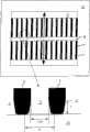
图6是微结构化的冷却器平面的示意性俯视图,显示微通道漏斗型入口区域的细节;Figure 6 is a schematic top view of a microstructured cooler plan showing details of the microchannel funnel-shaped inlet region;
图7示意性表示冷却器和具有与热阻定义相关的参数的CPU之间的连接;Figure 7 schematically represents the connection between a cooler and a CPU with parameters related to the definition of thermal resistance;
图8表示与现有技术冷却器相比,本发明冷却器的热阻与流速的关系;以及Figure 8 shows the relationship between the thermal resistance and the flow rate of the cooler of the present invention compared with the cooler of the prior art; and
图9表示与现有技术冷却器相比,本发明冷却器的热阻与压强损失的关系。Fig. 9 shows the relationship between the thermal resistance and the pressure loss of the cooler of the present invention compared with the cooler of the prior art.
具体实施方式Detailed ways
在所有附图中,相同的部分和零件具有相同的参考标号。读者也可以参看附带的参考标号表。In all figures, the same parts and components have the same reference numerals. The reader is also referred to the accompanying list of reference numerals.
图1显示金属箔1的各个参数,它们的优化将导致冷却器功率损失最小以及热接触面与流入冷却器的冷却剂之间的温差最小、或者冷却能力最大。在尚未焊接/钎焊的金属箔1中,通道显示为凹部2。参数是通道宽度b、通道深度t、通道间距(腹部宽度)s和残余箔厚度r。此外,结构化区的宽度f表示在金属箔1上。Figure 1 shows the various parameters of the
图1a显示结合在一起的结构化基板5和三个结构化金属箔1的堆叠。厚度为g的基板5在其中形成凹部,该凹部与相邻金属箔中形成的相应凹部一起形成与基板5的热接触面相邻的第一通道层中的通道2’。第一通道层中的通道2’的深度t’。另外两个金属箔1结合在基板5和第一金属箔的堆叠上形成具有通道2的另外通道层。这些通道2的深度t小于第一通道层的深度t’。Figure 1a shows a
图2显示热接触CPU处理器4的冷却器3。在这种情况下,冷却器3包括四片金属箔1,每片金属箔具有例如四个冷却通道2。通道之间的腹部在附图中是不可见的。每个金属箔1的通道2在其末端是封闭的。朝向CUP处理器4的最下端金属箔1’的冷却通道被基板厚度为g的基板5封闭。基板也具有与相邻金属箔1’的通道重合的通道,从而形成通道2’的共同结构。FIG. 2 shows the
基板5用于通过热接触面6吸收CPU处理器4产生的热量。为此,CPU处理器4在热接触面6的区域通过具有良好导热率的结合剂7(例如导热膏、焊料、导热胶)接触基板5。CPU处理器4装在CPU支撑板8上。The
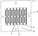
垂直定向的分隔室10大致在其中心穿过金属箔1。分隔室设计成是垂直于图形平面延伸延伸并与通道2相交的间隙。此外,两个收集室11也基本成直角穿过金属箔。通道也通向这些收集室。The vertically oriented
金属箔1和基板5的堆叠中止于顶部的盖板13。还可以提供分隔件14,它可以设计成单独件或者与盖板13集成。在分隔件中设置有入口室20和两个出口室21。入口室与分隔室10连通,收集室11与出口室连通。从图中可以明显看出,入口室和出口室按照本发明的方式分别朝分隔室和收集室变细。在盖板中具有连接件,即入口颈部15和出口颈部16。入口颈部与入口室连通,出口颈部与出口室连通。The stack of
来自外部冷却管路的冷却剂通过入口颈部15进入冷却器3,并经过此颈部到达入口室20。冷却剂从入口室流入分隔室10,由此直接流入所有通道2、2’。从图中可以看出,向下流入分隔室的冷却剂直接到达基板5,在基板上产生明显冷却作用。在其流过通道之后,冷却剂流入收集室11,由此经过出口室21循环到出口颈部16。冷却剂由此再次流入外部冷却管路。Coolant from the external cooling line enters the
图3a到3d表示其中包含通道2和位于之间的腹部9的金属箔的示意性俯视图。通道彼此平行设置并位于称为换热面的区域内。此区域由通道2覆盖的区域形成。Figures 3a to 3d show schematic top views of a metal foil with
分隔室10用于使微结构通道内的压强损失最小,其结果是使与减小冷却器和整个冷却系统(包括冷却剂泵和液体软管)尺寸相关的所需冷却剂流速最小,并优化它们。金属箔1基本在热接触面区域被分隔室中断(“分隔通道设计”)。The
在图3a到图3d中,在一个冷却器平面中的分隔室10显示为与通道2以及通道之间的腹部9相交的间隙。In Figures 3a to 3d the
所有通道2与分隔室10连通。尽管通道2仅仅从图3a所示的金属箔1部分地凹入使得在金属箔中剩下残余箔厚度,但间隙10构成穿过金属箔1的狭槽。在叠置多个这种金属箔时,形成接收冷却剂的通道2,通道2在金属箔平面内延伸。不同地是,由间隙形成的分隔室在冷却器的整个内部区域上延伸。All
此外,图3a到图3d显示了通道2在其外末端通向收集室11。流出通道2的冷却剂进入收集室,并由此经过出口室和出口颈部流出(图2)。出口室位于收集室之一的上方。这种循环冷却剂的方式使其可以达到良好的冷却能力。Furthermore, FIGS. 3 a to 3 d show that the
在图3a中,分隔室10和收集室11是完全穿通的。此外,通道2彼此直接相对地设置。In Fig. 3a, the
本发明的分隔通道设计的变体显示在图3b中。与图3a所示的设计的不同在于,通道2之间每隔一个的腹部9伸到分隔室10和收集室11以外,从而中断分隔室和收集室。这增大了设计的机械稳定性,并且在金属箔厚度小时尤其是优选的。A variant of the divided channel design of the present invention is shown in Figure 3b. The difference to the design shown in FIG. 3 a is that every
为了从冷却器排出冷却剂,可以具有两个连接件(图2),由此排出冷却剂。在流过通道2后,冷却剂经过出口侧收集室11流入出口室,并由此流出冷却器。In order to drain the coolant from the cooler, there may be two connections ( FIG. 2 ), through which the coolant is drained. After flowing through the
金属箔1具有通道2和在它们之间延伸的腹部9的另一变体如图3c所示。在这种情况下,通道由其分支的分隔室10以及通道通向其中的收集室11基本穿过整个冷却器,使得冷却剂可从分隔室循环到通道中,再经过收集室从通道返回。Another variant of the
通道2和腹部9在换热面的排列与图3a的不同之处在于,被分隔室10彼此分开的两个通道区的通道和腹部彼此相对偏移。结果提高了湍流的行为,这导致压强损失减小,从而进一步提高热传递。The arrangement of the
在另一变体中,在通道2之间的所有腹部9都穿过分隔室10和收集室11,如图3d所示。此实施例与图3b所示的实施例明显不同,图3b中仅是每隔一个的腹部穿过分隔室和收集室。此实施例比图3b所示的实施例甚至强度更高。In another variant, all the
在图4a中,以立体图显示了本发明的微结构化的冷却器3。用于与CPU热连接的热接触面处于底侧,在图中不可见。在顶侧可以看到入口颈部15和出口颈部16。In Fig. 4a, a
分隔件和盖件的详细图显示在图4b到4e中。在各个图中,分隔件和盖件未分开地图示。Detailed views of the divider and cover are shown in Figures 4b to 4e. In the respective figures, the partition and the cover are not shown separately.
图4b是此分隔和盖件13、14的立体图。在盖件中可以看到凹部,这代表入口室20和出口室21。入口室基本在冷却器的中心区延伸,从而其可与分隔室连通。出口室设计成U形,其两个分支位于冷却器3的侧部区域,从而可与也位于此的收集室连通。出口室具有两个出口,两个出口在冷却器的任一侧面在整个通道长度上延伸。收集室通过出口室的U形结构连通。Figure 4b is a perspective view of the partition and
入口室20到分隔室10以及出口室21到收集室11的过渡设计成,它们分别朝分隔室和收集室变细。在图示的情况下,它们具有锥形。这显示在图4c中。此图显示了分隔和盖件13、14沿图4d的线A-A的截面。The transitions from
入口室20的顶部宽度m优选地对应于冷却剂入口颈部的截面(图5),在图示情况下是7mm。入口室朝分隔室变细到宽度x,在图示情况下是3mm。出口室21也具有变细的出口。这些出口的顶部宽度n优选地对应于冷却剂出口颈部的截面,在图示情况下是7mm。出口室的出口朝收集室变细到宽度y,在图示情况下是3mm。入口室和出口室具有基本垂直侧壁的区域的高度为h2,而上述室变细区域的高度为h1。The top width m of the
这种分隔和盖件13、14可以用于分隔室宽度b10为0.7mm以及收集室宽度b11为1.5mm的冷却器中。在这种情况下,通道宽度b可以是3mm。Such partitions and covers 13 , 14 can be used in coolers with a compartment width b10 of 0.7 mm and a collection chamber width b11 of 1.5 mm. In this case, the channel width b may be 3 mm.
图4d显示了分隔和盖件13、14的俯视图。基本在中心区,显示了入口室20具有朝分隔室10的锥形。入口室左端被盖件13区域中的重叠部覆盖,并且仅仅出于此原因而表示为虚线。还显示了出口室21的U形区,其作为分隔和盖件中的凹部也是可见的。在出口室的腿部,朝收集室11的锥形变细是可见的。FIG. 4d shows a top view of the partition and
图4e表示分隔和盖件13、14的另一个截面,在此情况下是沿图4d的线B-B。在此截面的右区域显示了入口室20,其由垂直壁形成,所述室向下变细,通到分隔室(未图示)。在剖视图的左区域显示了U形出口室21的连接部分。Fig. 4e shows another section through the partition and
图5也是以剖视图显示了分隔和盖件13、14以及在下方连接所述件的通道层,此通道层与分隔和盖件间隔一定距离。各个组件已经讨论过了。FIG. 5 also shows in section the partition and cover
从此图中可以看出,入口室20从对应于入口颈部15的截面的宽度m变细到对应于分隔室10的宽度b10的宽度x。同样,从图中还可以看出,出口室21从对应于出口颈部16的截面的宽度n变细到对应于收集室11的宽度b11的宽度y。It can be seen from this figure that the
这里需要注意的是,宽度x至少等于分隔室10的间隙宽度b10。优选地,宽度x略大于宽度b10,从而在入口室20与分隔室未精确叠置时不妨碍冷却剂通过安装公差流出。It should be noted here that the width x is at least equal to the gap width b10 of the
同样,宽度y至少等于收集室11的间隙宽度b11。优选地,宽度y略大于宽度b11,从而在收集室11与出口室21未精确叠置时不妨碍冷却剂通过安装公差流出。Likewise, the width y is at least equal to the gap width b11 of the
除了分隔室10以及入口室20和出口室21的形状,图6所示并且在制造工艺中特别实现的漏斗状通道入口的锥形也有助于减小压强损失。In addition to the shape of the
为此,图6显示了具有通道2和位于它们之间的腹部9、以及图3a已经显示的分隔室10和收集室11的金属箔1。箭头另外地表示冷却剂流过通道的方向。图下部的放大详细图显示了具有通道入口开口的通道入口的漏斗形状。黑色表示的区域为通道2之间的腹部9。在此详细图的下部,分隔室10是可见的。在这种情况下,冷却剂从底部进入通道。To this end, FIG. 6 shows a
在冷却剂流动方向进入通道2的入口区域锥形(k>1=b)减小了冷却剂进入微通道的流动阻力。限定到平均宽度b的通道延伸到长度为E的通道中。The taper (k>1=b) of the inlet area into the
通道入口的这种形状例如可以通过特殊选择架构化时的刻蚀条件实现。例如,通道2可以在例如由美国的Chemcut提供的一种商用系统中刻蚀形成。为此,铜坯(尺寸:610mm×480mm)通过浓度为3mol/l的CuCl2溶液在温度为50℃、喷射压力为2bar、输送速度为0.6m/min下被结构化,将不需要刻蚀的部分(腹部、金属箔的边界)在刻蚀过程中用耐蚀剂覆盖。Such a shape of the channel opening can be achieved, for example, by a special selection of the etching conditions during structuring. For example, the
进入通道的入口形状优选地设置成k/l比值在1.1到3之间,更优选地在1.2到1.8之间。入口区域的长度E优选地从100到2000μm,更优选地从200到400μm。有关这一方面,读者可以参见图6的示意图。The inlet shape of the inlet channel is preferably set so that the k/l ratio is between 1.1 and 3, more preferably between 1.2 and 1.8. The length E of the inlet region is preferably from 100 to 2000 μm, more preferably from 200 to 400 μm. In this regard, the reader is referred to the schematic diagram in FIG. 6 .
图7显示了冷却器3和CPU4之间的连接以及在它们之间的导热胶层7的示意图,其中具有定义热阻所需的相关参数。FIG. 7 shows a schematic diagram of the connection between the
其中,Tinlct和Toutlct分别指流入和流出冷却器的冷却剂温度,Tm是冷却器中冷却剂的平均温度,Tcs是冷却器热接触面的表面温度,TCPU是CPU的表面温度,“power”是输入CPU的功率。where Tinlct and Toutlct refer to the coolant temperature flowing into and out of the cooler respectively, Tm is the average temperature of the coolant in the cooler, Tcs is the surface temperature of the thermal contact surface of the cooler, and TCPU is the surface temperature of the CPU , "power" is the power input to the CPU.
为了测试本发明冷却器与传统冷却器相比的性能,执行以下测试:In order to test the performance of the cooler of the present invention compared to conventional coolers, the following tests were performed:
实施例/对比实施例:Example/Comparative Example:
为了优化本发明冷却器的性能,可以根据具体的应用设计通道宽度、通道深度、通道间距、残余箔厚度和基板厚度,更具体地考虑微结构化的冷却器的冷却能力与体积之比,并针对,例如,底面积为12.0×12.0mm和功率输出为200W的参考CPU进行优化。由此定义描述冷却器冷却能力的各个关键数字。In order to optimize the performance of the cooler of the present invention, the channel width, channel depth, channel spacing, residual foil thickness and substrate thickness can be designed according to the specific application, more specifically considering the cooling capacity to volume ratio of the microstructured cooler, and Optimized for, for example, a reference CPU with a base area of 12.0 x 12.0mm and a power output of 200W. Various key figures describing the cooling capacity of the cooler are thus defined.
表1指出了重要影响因素。Table 1 points out the important influencing factors.
表1Table 1
冷却器的特性例如是WO 04/032231A中给出的那些特性。The characteristics of the cooler are for example those given in WO 04/032231A.
为了比较,使用传统冷却器(ArdexP(
功率数据总结在表2中,显示了示例性比较冷却器ArdexP和本发明优化的微结构化冷却器。The power data is summarized in Table 2, showing an exemplary comparative cooler ArdexP and the optimized microstructured cooler of the present invention.
表2Table 2

在相同条件下,在满负荷下对冷却表1所述的参考CPU进行对比测试。测试条件列于表3。Under the same conditions, the reference CPU described in Cooling Table 1 was tested under full load. The test conditions are listed in Table 3.
表3:ArdexPTable 3: ArdexP
本发明的冷却器:The cooler of the present invention:
冷却器是由结构化的基板(厚度:0.3mm)和8片结构化的箔(厚度:0.2mm)制成。The cooler is made of a structured substrate (thickness: 0.3 mm) and 8 pieces of structured foil (thickness: 0.2 mm).
表4:结构化的箔的几何特性Table 4: Geometric properties of structured foils
表5:本发明的冷却器Table 5: Coolers of the present invention
表6:测试结果-本发明冷却器和传统冷却器之间的比较Table 6: Test Results - Comparison Between the Cooler of the Invention and the Conventional Cooler
这些关键数字清楚地表明,本发明的冷却器在所有方面具有较大优势。These key figures clearly show that the cooler of the present invention is superior in all respects.
热阻减小37.5%使冷却器具有明显改进的散热和较高的效率。如果计算机具有高性能CPU或者是具有很多CPU的大型计算机,由于必须冷却几kW的热输出,此性能特别相关。The 37.5% reduction in thermal resistance enables the cooler to have significantly improved heat dissipation and higher efficiency. This performance is especially relevant if the computer has a high performance CPU or is a large computer with many CPUs due to the heat output of several kW that must be cooled.
温度差减小6℃直接导致冷却系统节省能量,其结果是节省运行成本。冷却水的流入温度例如可以增大这个数值,从而对冷却系统的效率具有极大影响。A reduction in the temperature difference of 6°C leads directly to energy savings in the cooling system and, as a result, savings in operating costs. The inflow temperature of the cooling water, for example, can increase this value, thereby having a great influence on the efficiency of the cooling system.
基于体积、ΔT和流速的冷却能力比传统冷却器大10.9倍,这表明使用这些冷却器可以实现相当高的封装密度(单位体积的CPU数量)。The cooling capacity based on volume, ΔT, and flow rate is 10.9 times greater than that of conventional coolers, indicating that considerably high packing densities (number of CPUs per unit volume) can be achieved using these coolers.
图8表示本发明冷却器和对比冷却器(ArdexP)的热阻Rth_c与预定流速之间的关系。从图8可以看出,在预定的边界条件下(也参见表2),本发明的冷却器在整个流动区具有明显减小的热阻。在1.2l/min的流速下,热阻可以减小37.5%。Fig. 8 shows the relationship between the thermal resistance Rth_c and the predetermined flow rate of the inventive cooler and the comparative cooler (ArdexP). It can be seen from FIG. 8 that under predetermined boundary conditions (see also Table 2), the cooler of the present invention has a significantly reduced thermal resistance over the entire flow area. At a flow rate of 1.2 l/min, the thermal resistance can be reduced by 37.5%.
图9表示本发明冷却器和对比冷却器(ArdexP)的热阻Rth_c与给定压强损失之间的关系。这里可以再次看出,热阻在整个范围内相对于对比冷却器被改进。Fig. 9 shows the relationship between the thermal resistance Rth_c and a given pressure loss of the inventive cooler and the comparative cooler (ArdexP). Here again it can be seen that the thermal resistance is improved over the entire range relative to the comparative cooler.
根据冷却系统的概念和根据相应的泵送性能,热阻可以按照图8(流速是预定的)或图9(压强损失是预定的)被特征化。Depending on the cooling system concept and depending on the corresponding pumping performance, the thermal resistance can be characterized according to Figure 8 (flow rate is predetermined) or Figure 9 (pressure loss is predetermined).
可以明显看出,本发明的冷却器在给定冷却器内的压强损失下具有最佳的热阻数值。It can be clearly seen that the cooler of the present invention has the best thermal resistance value for a given pressure loss in the cooler.
在例如130mbar的容许压强损失下,本发明冷却器的热阻小于0.050K/W,而现有技术冷却器的热阻小于0.08K/W。Under the allowable pressure loss of eg 130mbar, the thermal resistance of the cooler of the present invention is less than 0.050K/W, while the thermal resistance of the prior art cooler is less than 0.08K/W.
可以理解的是,这里描述的例子和实施例仅仅是用于解释的目的,基于此的各种修改和变化以及本说明书中描述的特征的组合对于本领域一般技术人员是明显的,并包括在所述的本发明的精神和范围内以及权利要求的范围内。这里所引用的所有文献、专利和专利申请通过引用包括在此。It can be understood that the examples and embodiments described here are for the purpose of explanation only, and that various modifications and changes based on these and combinations of features described in this specification will be obvious to those skilled in the art, and are included in within the spirit and scope of the invention as described and within the scope of the appended claims. All literature, patents, and patent applications cited herein are hereby incorporated by reference.
标号列表label list
1 金属箔1 metal foil
2,2’ 通道2, 2' channel
3 微结构化的冷却器3 Microstructured cooler
4 CUP处理器4 CUP processor
5 基板5 Substrate
6 热接触表面6 Thermal contact surface
7 TIM2(热界面材料)7 TIM2 (Thermal Interface Material)
8 CUP支撑板8 CUP support board
9 腹部9 abdomen
10 分隔室10 compartments
11 收集室11 collection room
12 金属箔1的边界12 Border of
13 盖板13 cover
14 分隔件14 Dividers
15 入口颈部15 entrance neck
16 出口颈部16 outlet neck
17 快速连接器17 quick connector
20 入口室20 entrance room
21 出口室21 exit room
b 通道宽度b channel width
b10 分隔室10的间隙宽度b10 Gap width of
b11 分隔室11的间隙宽度b11 Gap width of
t,t’ 通道深度t, t' channel depth
s 通道间距(腹部宽度)s channel spacing (abdomen width)
r 残余箔厚度r Residual foil thickness
f 金属箔1的结构化区的宽度f Width of the structured area of the
g 基板厚度g substrate thickness
x 入口室20的最小宽度x minimum width of
m 入口室20的最大宽度m Maximum width of
y 出口分隔室21的最小宽度y Minimum width of
n 出口分隔室21的最大宽度n Maximum width of
k 通道入口的漏斗宽度k funnel width at channel entrance
l 平行通道壁区域的漏斗宽度l The width of the funnel in the area parallel to the wall of the channel
E 漏斗形通道入口的深度E Depth of the entrance of the funnel-shaped channel
Claims (32)
Applications Claiming Priority (2)
| Application Number | Priority Date | Filing Date | Title |
|---|---|---|---|
| DE102005033150ADE102005033150A1 (en) | 2005-07-13 | 2005-07-13 | Microstructured cooler and its use |
| DE102005033150.5 | 2005-07-13 |
Publications (2)
| Publication Number | Publication Date |
|---|---|
| CN101218672A CN101218672A (en) | 2008-07-09 |
| CN100565856Ctrue CN100565856C (en) | 2009-12-02 |
Family
ID=37575524
Family Applications (1)
| Application Number | Title | Priority Date | Filing Date |
|---|---|---|---|
| CNB2006800252504AExpired - Fee RelatedCN100565856C (en) | 2005-07-13 | 2006-07-12 | Microstructured cooler and use thereof |
Country Status (9)
| Country | Link |
|---|---|
| US (1) | US7987899B2 (en) |
| EP (1) | EP1790007B1 (en) |
| JP (1) | JP2009501439A (en) |
| KR (1) | KR20080039413A (en) |
| CN (1) | CN100565856C (en) |
| AT (1) | ATE396498T1 (en) |
| DE (2) | DE102005033150A1 (en) |
| ES (1) | ES2306434T3 (en) |
| WO (1) | WO2007006590A2 (en) |
Cited By (1)
| Publication number | Priority date | Publication date | Assignee | Title |
|---|---|---|---|---|
| CN102316706A (en)* | 2010-06-29 | 2012-01-11 | 通用电气公司 | Have the heat sink of C shape manifold and the cooling of milli passage |
Families Citing this family (44)
| Publication number | Priority date | Publication date | Assignee | Title |
|---|---|---|---|---|
| US7836597B2 (en) | 2002-11-01 | 2010-11-23 | Cooligy Inc. | Method of fabricating high surface to volume ratio structures and their integration in microheat exchangers for liquid cooling system |
| US8464781B2 (en) | 2002-11-01 | 2013-06-18 | Cooligy Inc. | Cooling systems incorporating heat exchangers and thermoelectric layers |
| US7591302B1 (en) | 2003-07-23 | 2009-09-22 | Cooligy Inc. | Pump and fan control concepts in a cooling system |
| US7913719B2 (en) | 2006-01-30 | 2011-03-29 | Cooligy Inc. | Tape-wrapped multilayer tubing and methods for making the same |
| WO2007120530A2 (en) | 2006-03-30 | 2007-10-25 | Cooligy, Inc. | Integrated liquid to air conduction module |
| US7715194B2 (en) | 2006-04-11 | 2010-05-11 | Cooligy Inc. | Methodology of cooling multiple heat sources in a personal computer through the use of multiple fluid-based heat exchanging loops coupled via modular bus-type heat exchangers |
| TW200934352A (en) | 2007-08-07 | 2009-08-01 | Cooligy Inc | Internal access mechanism for a server rack |
| WO2009058269A1 (en)* | 2007-10-29 | 2009-05-07 | Jan Vetrovec | Heat transfer device |
| US8479806B2 (en) | 2007-11-30 | 2013-07-09 | University Of Hawaii | Two-phase cross-connected micro-channel heat sink |
| US9297571B1 (en) | 2008-03-10 | 2016-03-29 | Liebert Corporation | Device and methodology for the removal of heat from an equipment rack by means of heat exchangers mounted to a door |
| US20090225514A1 (en) | 2008-03-10 | 2009-09-10 | Adrian Correa | Device and methodology for the removal of heat from an equipment rack by means of heat exchangers mounted to a door |
| JP4992808B2 (en) | 2008-04-16 | 2012-08-08 | トヨタ自動車株式会社 | Manufacturing method of heat exchanger |
| US8254422B2 (en) | 2008-08-05 | 2012-08-28 | Cooligy Inc. | Microheat exchanger for laser diode cooling |
| US20100071883A1 (en)* | 2008-09-08 | 2010-03-25 | Jan Vetrovec | Heat transfer device |
| SG189779A1 (en)* | 2009-10-20 | 2013-05-31 | Agency Science Tech & Res | A cooling device, an assembly, and methods for lowering temperature in a chemical reaction |
| DE102010045905B3 (en)* | 2010-09-17 | 2012-03-29 | Karlsruher Institut für Technologie | Cross-flow micro heat exchanger |
| JP5472443B2 (en)* | 2010-12-24 | 2014-04-16 | トヨタ自動車株式会社 | Cooler |
| US9245836B2 (en) | 2012-06-28 | 2016-01-26 | Soitec | Interposers including fluidic microchannels and related structures and methods |
| US8912643B2 (en) | 2012-12-10 | 2014-12-16 | General Electric Company | Electronic device cooling with microjet impingement and method of assembly |
| US20140251585A1 (en)* | 2013-03-05 | 2014-09-11 | The Boeing Company | Micro-lattice Cross-flow Heat Exchangers for Aircraft |
| JP6115959B2 (en)* | 2013-12-11 | 2017-04-19 | 株式会社フィルテック | Fluid heat exchange device |
| KR102019573B1 (en) | 2014-10-30 | 2019-09-06 | 도쿄엘렉트론가부시키가이샤 | Substrate placing table |
| CN107924897B (en)* | 2015-09-18 | 2020-10-23 | 株式会社T.Rad | Laminated Core Type Heat Sink |
| US10527362B2 (en) | 2015-09-21 | 2020-01-07 | Lockheed Martin Corporation | Integrated multi-chamber heat exchanger |
| US10371462B2 (en)* | 2015-09-21 | 2019-08-06 | Lockheed Martin Corporation | Integrated multi-chamber heat exchanger |
| US10352632B2 (en)* | 2016-05-26 | 2019-07-16 | Northrop Grumman Systems Corporation | Heat transfer utilizing vascular composites and field induced forces |
| US10139168B2 (en) | 2016-09-26 | 2018-11-27 | International Business Machines Corporation | Cold plate with radial expanding channels for two-phase cooling |
| EP3700697B1 (en) | 2017-10-26 | 2022-08-24 | Fraunhofer-Gesellschaft zur Förderung der angewandten Forschung e.V. | Method for producing cast parts having microchannels |
| CN107734840B (en)* | 2017-11-29 | 2023-08-18 | 中国电子科技集团公司第二十六研究所 | Liquid-cooled cooling structure based on printed circuit board three-dimensional microchannel array |
| JP7047577B2 (en)* | 2018-04-27 | 2022-04-05 | 株式会社デンソー | Heat exchanger |
| CN110543069A (en)* | 2018-05-28 | 2019-12-06 | 中强光电股份有限公司 | Liquid-cooled radiator |
| US10553522B1 (en) | 2018-08-13 | 2020-02-04 | International Business Machines Corporation | Semiconductor microcooler |
| US10553516B1 (en) | 2018-08-13 | 2020-02-04 | International Business Machines Corporation | Semiconductor microcooler |
| US10490480B1 (en) | 2018-08-21 | 2019-11-26 | International Business Machines Corporation | Copper microcooler structure and fabrication |
| US11545410B2 (en)* | 2018-12-17 | 2023-01-03 | Intel Corporation | Enhanced systems and methods for improved heat transfer from semiconductor packages |
| CN110300509A (en)* | 2019-06-29 | 2019-10-01 | 联想(北京)有限公司 | A kind of radiator |
| CN111081655B (en)* | 2019-12-19 | 2021-10-22 | 青岛歌尔智能传感器有限公司 | Electronic packaging structure and manufacturing method thereof |
| CN111632565B (en)* | 2020-05-24 | 2021-09-03 | 西安交通大学 | Micro-channel rapid cooling device for preparing nano powder by supercritical hydrothermal synthesis technology |
| CN112435976B (en)* | 2020-11-06 | 2024-04-16 | 西安交通大学 | Ultralow flow resistance micro-channel radiator based on bionic fractal structure and manufacturing method thereof |
| KR102593733B1 (en)* | 2021-05-27 | 2023-10-25 | 주식회사 아모그린텍 | Ceramic substrate with heat sink and manufacturing method thereof |
| CN114353562B (en)* | 2021-11-30 | 2024-06-21 | 中国船舶重工集团公司第七一九研究所 | Heat exchange channel structure of printed circuit board heat exchanger and printed circuit board heat exchanger |
| KR102585892B1 (en)* | 2022-04-14 | 2023-10-06 | 창원대학교 산학협력단 | semiconductor cooling device |
| EP4390291A1 (en)* | 2022-12-23 | 2024-06-26 | TechN GmbH | Apparatus, system and method for cooling a processor |
| US20240385648A1 (en)* | 2023-05-15 | 2024-11-21 | Apple Inc. | Head mountable display |
Citations (1)
| Publication number | Priority date | Publication date | Assignee | Title |
|---|---|---|---|---|
| WO2004032231A2 (en)* | 2002-10-02 | 2004-04-15 | Atotech Deutschland Gmbh | Micro-structure cooling device and use thereof |
Family Cites Families (14)
| Publication number | Priority date | Publication date | Assignee | Title |
|---|---|---|---|---|
| US5598632A (en)* | 1994-10-06 | 1997-02-04 | The United States Of America As Represented By The Administrator Of The National Aeronautics And Space Administration | Method for producing micro heat panels |
| DE19708472C2 (en)* | 1997-02-20 | 1999-02-18 | Atotech Deutschland Gmbh | Manufacturing process for chemical microreactors |
| DE19710716C2 (en) | 1997-03-14 | 2001-05-10 | Fraunhofer Ges Forschung | Device for cooling electronic components |
| DE19710783C2 (en)* | 1997-03-17 | 2003-08-21 | Curamik Electronics Gmbh | Coolers for use as a heat sink for electrical components or circuits |
| DE19853750A1 (en)* | 1998-08-04 | 2000-02-17 | Schulz Harder Juergen | Heat sink device for electrical or electronic component, circuit or module |
| US6386278B1 (en)* | 1998-08-04 | 2002-05-14 | Jurgen Schulz-Harder | Cooler |
| US6152215A (en)* | 1998-12-23 | 2000-11-28 | Sundstrand Corporation | High intensity cooler |
| JP3681581B2 (en)* | 1999-07-30 | 2005-08-10 | ファナック株式会社 | Cooling device and surface light emitting device including the same |
| JP2003302176A (en)* | 2001-08-07 | 2003-10-24 | Denso Corp | Boiling cooler |
| EP1506054B1 (en)* | 2002-03-26 | 2012-07-25 | Peter Prechtl | Micro-reactor and micro-channel heat exchanger |
| US8087452B2 (en)* | 2002-04-11 | 2012-01-03 | Lytron, Inc. | Contact cooling device |
| US7115987B2 (en)* | 2003-12-31 | 2006-10-03 | Intel Corporation | Integrated stacked microchannel heat exchanger and heat spreader |
| JP2007127398A (en)* | 2005-10-05 | 2007-05-24 | Seiko Epson Corp | Heat exchanger, heat exchanger manufacturing method, liquid cooling system, light source device, projector, electronic device unit, electronic equipment |
| US7537047B2 (en)* | 2006-03-23 | 2009-05-26 | Foxconn Technology Co., Ltd. | Liquid-cooling heat sink |
- 2005
- 2005-07-13DEDE102005033150Apatent/DE102005033150A1/ennot_activeWithdrawn
- 2006
- 2006-07-12ATAT06776247Tpatent/ATE396498T1/ennot_activeIP Right Cessation
- 2006-07-12DEDE602006001286Tpatent/DE602006001286D1/enactiveActive
- 2006-07-12JPJP2008520809Apatent/JP2009501439A/enactivePending
- 2006-07-12USUS11/995,221patent/US7987899B2/ennot_activeExpired - Fee Related
- 2006-07-12KRKR1020087003467Apatent/KR20080039413A/ennot_activeWithdrawn
- 2006-07-12WOPCT/EP2006/006948patent/WO2007006590A2/enactiveIP Right Grant
- 2006-07-12EPEP06776247Apatent/EP1790007B1/ennot_activeNot-in-force
- 2006-07-12ESES06776247Tpatent/ES2306434T3/enactiveActive
- 2006-07-12CNCNB2006800252504Apatent/CN100565856C/ennot_activeExpired - Fee Related
Patent Citations (1)
| Publication number | Priority date | Publication date | Assignee | Title |
|---|---|---|---|---|
| WO2004032231A2 (en)* | 2002-10-02 | 2004-04-15 | Atotech Deutschland Gmbh | Micro-structure cooling device and use thereof |
Cited By (2)
| Publication number | Priority date | Publication date | Assignee | Title |
|---|---|---|---|---|
| CN102316706A (en)* | 2010-06-29 | 2012-01-11 | 通用电气公司 | Have the heat sink of C shape manifold and the cooling of milli passage |
| CN102316706B (en)* | 2010-06-29 | 2015-07-29 | 通用电气公司 | Have C shape manifold and milli passage cooling heat sink |
Also Published As
| Publication number | Publication date |
|---|---|
| EP1790007A2 (en) | 2007-05-30 |
| JP2009501439A (en) | 2009-01-15 |
| ATE396498T1 (en) | 2008-06-15 |
| US7987899B2 (en) | 2011-08-02 |
| ES2306434T3 (en) | 2008-11-01 |
| WO2007006590A3 (en) | 2007-03-29 |
| US20080196875A1 (en) | 2008-08-21 |
| KR20080039413A (en) | 2008-05-07 |
| DE102005033150A1 (en) | 2007-01-25 |
| DE602006001286D1 (en) | 2008-07-03 |
| WO2007006590A2 (en) | 2007-01-18 |
| CN101218672A (en) | 2008-07-09 |
| EP1790007B1 (en) | 2008-05-21 |
Similar Documents
| Publication | Publication Date | Title |
|---|---|---|
| CN100565856C (en) | Microstructured cooler and use thereof | |
| JP4460856B2 (en) | Microstructure cooler and its use | |
| TWI274244B (en) | Cold plate | |
| US7017655B2 (en) | Forced fluid heat sink | |
| JP5135225B2 (en) | Use of a micro heat transfer device as a fluid cooler for micro heat transfer and electronic devices | |
| US7764494B2 (en) | Liquid cooled module | |
| US7259965B2 (en) | Integrated circuit coolant microchannel assembly with targeted channel configuration | |
| CN105637632B (en) | Cooler and semiconductor module using the same | |
| JP2006086503A (en) | Method and equipment for efficient perpendicular fluid transfer for cooling exoergic device | |
| JP2006522463A (en) | Optimal spreader system, apparatus and method for micro heat exchange cooled by fluid | |
| JP2006522463A5 (en) | ||
| JP2006515054A (en) | Method and apparatus for efficient vertical fluid transport for cooling a heat generating device | |
| CN111328245B (en) | Return type jet microchannel radiator and heat dissipation method | |
| Shen et al. | Thermofluids performances on innovative design with multi-circuit nested loop applicable for double-layer microchannel heat sinks | |
| US7992625B1 (en) | Fluid-operated heat transfer device | |
| JP2003511648A (en) | Heat exchanger for electronic heat pump | |
| CN114649284A (en) | A rib-row bionic structure microchannel radiator | |
| JP2008111653A (en) | Cooler | |
| JP2008530482A (en) | Heat exchanger manufacturing method, micro heat exchanger manufacturing method, and micro heat exchanger | |
| CN114639647A (en) | Micro-channel heat dissipation structure and microelectronic chip structure | |
| CN219248454U (en) | Liquid cooling heat radiator | |
| RU107582U1 (en) | MICROCHANNEL HEAT EXCHANGER WITH NANORELIEF | |
| CN120149273A (en) | Heat dissipation unit, heat dissipation device and electronic device | |
| HK1060653A (en) | Microstructure cooling device and use thereof |
Legal Events
| Date | Code | Title | Description |
|---|---|---|---|
| C06 | Publication | ||
| PB01 | Publication | ||
| C10 | Entry into substantive examination | ||
| SE01 | Entry into force of request for substantive examination | ||
| C14 | Grant of patent or utility model | ||
| GR01 | Patent grant | ||
| CF01 | Termination of patent right due to non-payment of annual fee | Granted publication date:20091202 Termination date:20160712 | |
| CF01 | Termination of patent right due to non-payment of annual fee |