CN100563585C - Be particularly useful for the instrument of laparoscopic surgery - Google Patents
Be particularly useful for the instrument of laparoscopic surgeryDownload PDFInfo
- Publication number
- CN100563585C CN100563585CCNB2005800450483ACN200580045048ACN100563585CCN 100563585 CCN100563585 CCN 100563585CCN B2005800450483 ACNB2005800450483 ACN B2005800450483ACN 200580045048 ACN200580045048 ACN 200580045048ACN 100563585 CCN100563585 CCN 100563585C
- Authority
- CN
- China
- Prior art keywords
- pawl
- actuator
- handle
- connection switch
- instrument
- Prior art date
- Legal status (The legal status is an assumption and is not a legal conclusion. Google has not performed a legal analysis and makes no representation as to the accuracy of the status listed.)
- Expired - Fee Related
Links
Images


Classifications
- A—HUMAN NECESSITIES
- A61—MEDICAL OR VETERINARY SCIENCE; HYGIENE
- A61B—DIAGNOSIS; SURGERY; IDENTIFICATION
- A61B17/00—Surgical instruments, devices or methods
- A61B17/28—Surgical forceps
- A—HUMAN NECESSITIES
- A61—MEDICAL OR VETERINARY SCIENCE; HYGIENE
- A61B—DIAGNOSIS; SURGERY; IDENTIFICATION
- A61B17/00—Surgical instruments, devices or methods
- A61B17/28—Surgical forceps
- A61B17/29—Forceps for use in minimally invasive surgery
- A61B17/2909—Handles
- A—HUMAN NECESSITIES
- A61—MEDICAL OR VETERINARY SCIENCE; HYGIENE
- A61B—DIAGNOSIS; SURGERY; IDENTIFICATION
- A61B17/00—Surgical instruments, devices or methods
- A61B17/12—Surgical instruments, devices or methods for ligaturing or otherwise compressing tubular parts of the body, e.g. blood vessels or umbilical cord
- A—HUMAN NECESSITIES
- A61—MEDICAL OR VETERINARY SCIENCE; HYGIENE
- A61B—DIAGNOSIS; SURGERY; IDENTIFICATION
- A61B17/00—Surgical instruments, devices or methods
- A61B2017/0042—Surgical instruments, devices or methods with special provisions for gripping
- A61B2017/00424—Surgical instruments, devices or methods with special provisions for gripping ergonomic, e.g. fitting in fist
- A—HUMAN NECESSITIES
- A61—MEDICAL OR VETERINARY SCIENCE; HYGIENE
- A61B—DIAGNOSIS; SURGERY; IDENTIFICATION
- A61B17/00—Surgical instruments, devices or methods
- A61B17/28—Surgical forceps
- A61B17/29—Forceps for use in minimally invasive surgery
- A61B17/2909—Handles
- A61B2017/2912—Handles transmission of forces to actuating rod or piston
- A61B2017/2919—Handles transmission of forces to actuating rod or piston details of linkages or pivot points
- A—HUMAN NECESSITIES
- A61—MEDICAL OR VETERINARY SCIENCE; HYGIENE
- A61B—DIAGNOSIS; SURGERY; IDENTIFICATION
- A61B17/00—Surgical instruments, devices or methods
- A61B17/28—Surgical forceps
- A61B17/29—Forceps for use in minimally invasive surgery
- A61B17/2909—Handles
- A61B2017/2925—Pistol grips
- A—HUMAN NECESSITIES
- A61—MEDICAL OR VETERINARY SCIENCE; HYGIENE
- A61B—DIAGNOSIS; SURGERY; IDENTIFICATION
- A61B17/00—Surgical instruments, devices or methods
- A61B17/28—Surgical forceps
- A61B17/29—Forceps for use in minimally invasive surgery
- A61B2017/2926—Details of heads or jaws
- A61B2017/2927—Details of heads or jaws the angular position of the head being adjustable with respect to the shaft
- A61B2017/2929—Details of heads or jaws the angular position of the head being adjustable with respect to the shaft with a head rotatable about the longitudinal axis of the shaft
- A—HUMAN NECESSITIES
- A61—MEDICAL OR VETERINARY SCIENCE; HYGIENE
- A61B—DIAGNOSIS; SURGERY; IDENTIFICATION
- A61B17/00—Surgical instruments, devices or methods
- A61B17/28—Surgical forceps
- A61B17/29—Forceps for use in minimally invasive surgery
- A61B2017/2946—Locking means
Landscapes
- Health & Medical Sciences (AREA)
- Surgery (AREA)
- Life Sciences & Earth Sciences (AREA)
- Medical Informatics (AREA)
- Animal Behavior & Ethology (AREA)
- Engineering & Computer Science (AREA)
- Biomedical Technology (AREA)
- Heart & Thoracic Surgery (AREA)
- Veterinary Medicine (AREA)
- Molecular Biology (AREA)
- Nuclear Medicine, Radiotherapy & Molecular Imaging (AREA)
- General Health & Medical Sciences (AREA)
- Public Health (AREA)
- Ophthalmology & Optometry (AREA)
- Reproductive Health (AREA)
- Vascular Medicine (AREA)
- Surgical Instruments (AREA)
Abstract
Description
Translated fromChinese本发明涉及一种仪器,尤其涉及一种用于腹腔镜手术亦称为“锁孔手术”的仪器。The invention relates to an instrument, in particular to an instrument for laparoscopic surgery, also known as "keyhole surgery".
本发明的目的在于提供一种简单的手动操作仪器,其中,该仪器的工具或所谓的效应器设置为可选择性地被锁固于指定位置,并且不必移动理想的手指握柄而将效应器自该锁固位置释放以操作该仪器。理想的手指握柄可以为但不绝对地例如三手指握柄,其中,小指、无名指及中指扣住该仪器的握柄部,并且食指、大姆指用于操作该仪器的效应器的主要功能,如一对剪刀或一对夹子。其给予了操作者如外科医生对仪器控制上的很大改良。It is an object of the present invention to provide a simple manually operated instrument in which the tool or so-called effector is arranged to be selectively locked in a designated position and the effector does not have to be removed from the ideal finger grip. Released from the locked position to operate the instrument. An ideal finger grip could be, but not absolutely, such as a three-finger grip, where the little, ring and middle fingers clasp the grip portion of the instrument, and the index and thumb are used for the primary function of operating the effector of the instrument , such as a pair of scissors or a pair of clips. It gives an operator such as a surgeon a great improvement in the control of the instrument.
即使第一次对人类实施腹腔镜检查是在1910年,直到1987年,腹腔镜技术才被广泛应用。从那时起,便存在着应用领域和手术方法领域中的激烈过程的变革。然而,腹腔镜仪器的发展很少涉及关于人体工学的改进。科学的测量表明外科医生要花掉十倍于进行开腹手术的精力来执行相同的腹腔镜程序。Even though laparoscopy was first performed on humans in 1910, laparoscopy was not widely used until 1987. Since then, there have been drastic process changes both in the field of application and in the field of surgical methods. However, the development of laparoscopic instruments has rarely involved ergonomic improvements. Scientific measurements show that it takes the surgeon ten times as much effort to perform the same laparoscopic procedure as performing an open surgery.
从美国专利第5480409、5893878、5383888、5792165、5976121、5488441、5735873及5868784号和WO9724072已知多种腹腔镜仪器的设计。即使已知的仪器在设计和功能方面有了很大的变化,但已知的仪器的共同点是其由包括一个或多个可移动部分的握柄组成,尤其包括扳机,用户如外科医生可以操纵该扳机以控制连接于管状元件或工具杆的悬臂部分的工具或效应器,该悬臂部分的其它部分与该握柄相连接。Various laparoscopic instrument designs are known from US Patent Nos. 5480409, 5893878, 5383888, 5792165, 5976121, 5488441, 5735873 and 5868784 and WO9724072. Even though known instruments vary widely in design and function, the known instruments have in common that they consist of a handle comprising one or more movable parts, including in particular a trigger, which a user such as a surgeon can The trigger is manipulated to control the tool or effector attached to the tubular member or the cantilevered portion of the tool shaft, the rest of which is attached to the handle.
美国专利第5,792,165号公开了一种对效应器操纵具有较大灵活性的仪器,其具有三个自由度:旋转、枢轴转动、及夹持。其它的效应器可以连接至且移除自该仪器的管状体。美国专利第5,792,165号公开的仪器也可以通过整合的马达和微处理器部分地控制该效应器的动作。US Patent No. 5,792,165 discloses an instrument with greater flexibility for effector manipulation, which has three degrees of freedom: rotation, pivoting, and clamping. Other effectors can be connected to and removed from the tubular body of the instrument. The apparatus disclosed in US Patent No. 5,792,165 can also control the action of the effector in part through an integrated motor and microprocessor.
美国专利第5,383,888号公开了一种与美国专利第5,792,165号所公开的功能基本相同的仪器。US Patent No. 5,383,888 discloses an instrument that functions substantially the same as that disclosed in US Patent No. 5,792,165.
美国专利第5,976,121号公开了一种用于操纵与腹腔镜相连接的仪器的握柄。US Patent No. 5,976,121 discloses a handle for manipulating an instrument connected to a laparoscope.
美国专利第5,735,873号公开了一种其握柄上具有棘齿机构的外科仪器,且于该外科仪器的端部设置有致动器及效应器。US Patent No. 5,735,873 discloses a surgical instrument with a ratchet mechanism on its handle, and an actuator and an effector are provided at the end of the surgical instrument.
美国专利第5,868,784号公开了一种具有用于锁固致动器的棘齿机构的外科仪器。US Patent No. 5,868,784 discloses a surgical instrument with a ratchet mechanism for locking the actuator.
WO9724072公开了一种具有允许仪器适应不同手大小的可调节握柄的腹腔镜仪器。该仪器包括用于将该扳机锁固于指定位置的锁固装置。WO9724072 discloses a laparoscopic instrument with an adjustable grip allowing the instrument to be adapted to different hand sizes. The instrument includes locking means for locking the trigger in a designated position.
上述的现有技术存在几个缺点:There are several shortcoming in above-mentioned prior art:
一个缺点是在大多数上述现有技术中的关于该仪器握柄的设计不利于人体工学,因为该仪器没有提供弯曲的手掌的工作位置和/或其需要移动手指进行仪器的操作,除食指外的其它手指必须操作仪器的主要功能。这会使外科医生的手部容易发生小的不受控制的移动。这种移动导致仪器的运转着的端部即效应器所处位置的相对大的且不希望有的移动。该不利的设计的结果是要试图抵消前述的不希望有的移动,此外,外科医生要花费十倍于进行开腹手术的精力来执行相同的腹腔镜程序。One disadvantage is that the design of the handle of the instrument in most of the above-mentioned prior art is not ergonomic because the instrument does not provide a working position for a bent palm and/or it requires movement of the fingers for operation of the instrument, except for the index finger The other fingers must operate the main function of the instrument. This can leave the surgeon prone to small uncontrolled movements of the hand. This movement results in a relatively large and undesired movement of the live end of the instrument, where the effector is located. The result of this disadvantageous design is to try to counteract the aforementioned unwanted movement, and moreover, the surgeon expends ten times the effort to perform the same laparoscopic procedure as performing a laparotomy.
关于一些前述仪器的另一个实质缺点是其技术上很复杂,从而使仪器生产成本高。因而,很大程度上讲,这些仪器要再使用数次。理论上讲,即使这些仪器可以百分百消毒,由柏林市KrankenhausMoabit,Lehrkrankenhaus der Humboldt Universitat zu的Fengler,Pahlke,Bisson和Kraas进行的外科研究“腹腔镜仪器的临床应用。功能及卫生学的预期临床研究”(“The Clinical suitability of laparoscopicinstrumentation.A prospective clinical study of function and hygiene”),其中,公开了在清洗过后,仪器保留了相对大量的血液残渣,其表明了存在病人会被感染的潜在风险。这可导致该病人严重患病甚至死亡。Another substantial disadvantage with respect to some of the aforementioned instruments is that they are technically complex, making the instruments expensive to produce. Thus, to a large extent, these instruments are reused several times. Theoretically, even if these instruments can be 100% sterilized, the surgical study "Clinical application of laparoscopic instruments. Functional and hygienic prospective clinical "The Clinical suitability of laparoscopic instrumentation. A prospective clinical study of function and hygiene", which discloses that after cleaning, the instrument retains a relatively large amount of blood residue, which indicates a potential risk of patient infection. This can lead to serious illness or even death in the patient.
关于腹腔镜仪器,存在可以锁固效应器的需要,比如但不限于在关闭位置和完全开启(activate)位置或在上述位置之间的一特定位置上安置一对握持钳。锁固尤其关系到如组织或血管的夹紧和定位。美国专利第5792165号、第5480409号、第5735873号、第5868784号和WO9724072所公开的仪器提供了不同的彼此啮合而用以在特定位置上锁固效应器的棘齿机构。所述专利文件中这些解决方案的实质性缺点是棘爪与棘齿轮的啮合和分离必须通过一个或更多的手指或整个不得不从其用于控制该效应器的扳机的自然位置上移开的手来执行。美国专利第5868784号公开了一种很复杂的仪器,其包括棘齿机构,用于将扳机锁固于指定位置。所述专利和WO9724072和美国专利第5735873号的实质性缺点是在该棘齿机构已开启后,扳机被锁固而不能做任何移动。With respect to laparoscopic instruments, there is a need to lock the effector, such as but not limited to, by placing a pair of gripping forceps in a closed position and a fully activated position or at a specific position in between. Locking relates in particular to the clamping and positioning of eg tissue or blood vessels. The instruments disclosed in US Pat. No. 5,792,165, No. 5,480,409, No. 5,735,873, No. 5,868,784 and WO9724072 provide different ratchet mechanisms that engage each other to lock the effector in a specific position. The substantial disadvantage of these solutions in said patent document is that the engagement and disengagement of the pawl from the ratchet must be done by one or more fingers or the whole has to be moved from its natural position for controlling the trigger of the effector hands to execute. US Patent No. 5868784 discloses a very complex instrument which includes a ratchet mechanism for locking the trigger in a designated position. A substantial disadvantage of said patent and WO9724072 and US Patent No. 5735873 is that the trigger is locked against any movement after the ratchet mechanism has been opened.
本发明的目的是弥补或至少减小一个或更多的相关于前述专利文件所公开的现有技术的缺点,尤其是相关于在指定打开位置上锁固该效应器的机构的功能性方面的缺点。同时,其目的是提供一种具有很简单结构的仪器,且该仪器的元件的实质部分可利用例如但不限于用塑料材料制成。这可导致相对较低的生产成本且由此支持该仪器作为消耗品的使用。而且,排除了由于仪器的不充分清洁而造成的传染。The object of the present invention is to remedy or at least reduce one or more of the disadvantages associated with the prior art disclosed in the aforementioned patent documents, especially with regard to the functional aspects of the mechanism for locking the effector in a given open position shortcoming. At the same time, the aim is to provide an instrument having a very simple structure and a substantial part of the elements of which can be made of, for example but not limited to, plastic material. This can lead to relatively low production costs and thus supports the use of the device as a consumable. Furthermore, contamination due to insufficient cleaning of the instruments is ruled out.
根据下述的详细描述和随后的权利要求限定的特征来实现本发明的目的。The objects of the invention are achieved according to the features defined in the following detailed description and the following claims.
在一个方面,本发明由包括握柄的仪器组成,该握柄设有致动器,其设置为通过联动机构影响安置于管状元件第一端部的效应器的操作,所述管状元件自其第二端部延伸进该仪器的握柄且连接于该联动机构的一部分,该联动机构包括与大致互补的棘爪相配合的棘齿条,通过连接开关启动和释放该棘爪的斜齿与该棘齿条的斜齿间的啮合,该连接开关通过柔性元件而连接至该棘爪,当该连接开关在第一位置时,通过偏压该棘爪以使其与该棘齿条相啮合,当该连接开关在第二位置时,该柔性元件施加拉力于该棘爪,仅当该柔性元件的拉力至少超过该棘爪的斜齿与该棘齿条的斜齿间摩擦力的相对的合力时,该棘爪才脱离该棘齿条,这样,即使在该连接开关从该第一位置移动至该第二位置之后,所述啮合仍可保持。In one aspect, the invention consists of an instrument comprising a handle provided with an actuator arranged to affect, through a linkage mechanism, the operation of an effector disposed at a first end of a tubular element from its second The two ends extend into the handle of the instrument and are connected to a portion of the linkage mechanism, which includes a ratchet rack cooperating with a substantially complementary pawl, the helical teeth of the pawl being activated and released by a connection switch and the engagement between helical teeth of a ratchet bar, the link switch being connected to the pawl by a flexible member, by biasing the pawl to engage the ratchet bar when the link switch is in the first position, When the connection switch is in the second position, the flexible element exerts a pulling force on the pawl only when the pulling force of the flexible element at least exceeds the relative resultant force of the friction between the helical teeth of the pawl and the helical teeth of the ratchet rack Only when the ratchet is disengaged from the ratchet rack, even after the connection switch moves from the first position to the second position, the engagement can still be maintained.
在优选实施例中,该棘爪与该棘齿条的斜互补齿允许该棘齿条相对于该棘爪的单向相对移动。因此,如前所述,仅当该连接开关处于关闭位置且该棘齿条相对于该棘爪移动时,斜齿与柔性元件的组合才允许该棘爪脱离该棘齿条,根据本发明,可以通过当该棘齿条优选地与该联动机构相连时该致动器的移动而达到上述目的。因此可以理解,可独立于该致动器而控制棘齿机构的连接开关,且通过该致动器而解除该棘齿机构的连接。这对达到完全控制该仪器是很重要的特性。如果由大致硬的元件代替该柔性元件,不会产生相应的影响。In a preferred embodiment, the oblique complementary teeth of the pawl and the ratchet bar allow unidirectional relative movement of the ratchet bar relative to the pawl. Thus, the combination of helical teeth and flexible elements allows the pawl to disengage from the ratchet bar only when the connection switch is in the closed position and the ratchet bar moves relative to the pawl, as previously described. According to the invention, This is achieved by the movement of the actuator when the ratchet bar is preferably connected to the linkage. It will thus be appreciated that the connection switch of the ratchet mechanism can be controlled independently of the actuator and the ratchet mechanism can be decoupled by the actuator. This is an important feature to achieve full control over the instrument. There is no corresponding effect if the flexible element is replaced by a substantially stiff element.
为进一步确保在该连接开关被移动至关闭位置后该棘齿机构不会不受控制地脱离,在一优选实施例中,该联动机构设有可在该优选的棘爪与棘齿条的斜齿间产生完全啮合的偏压元件。In order to further ensure that the ratchet mechanism will not disengage uncontrollably after the connection switch is moved to the closed position, in a preferred embodiment, the linkage mechanism is provided with an angle that can be adjusted between the preferred ratchet and ratchet bar. A biasing element that creates a full mesh between the teeth.
在优选实施例中,通过一种已知类型的转轮,使该管状元件和安置于其第一端部的效应器绕该管状元件的纵轴线并相对于该握柄旋转。In a preferred embodiment, the tubular element and the effector disposed at its first end are rotated about the longitudinal axis of the tubular element and relative to the handle by means of a rotating wheel of a known type.
腹腔镜操作可能会持续相对较长的时间。因此,尽可能地调整好仪器以适应操作者的手是很重要的,既相对于如致动器和连接开关这样的功能设备的定位,也相对于大小。因此,根据本发明的一种优选实施例的仪器设有至少一个可调节部分,能调节握柄至适合仪器操作者手的大小。在一个实施例中,仪器的至少一个可调节部分安置在该握柄的背部。Laparoscopic procedures may last a relatively long time. Therefore, it is important to adjust the instrument as well as possible to the operator's hand, both with respect to the positioning and size of functional devices such as actuators and connected switches. Therefore, the instrument according to a preferred embodiment of the present invention is provided with at least one adjustable portion, enabling the handle to be adjusted to the size of the hand of the operator of the instrument. In one embodiment, at least one adjustable portion of the instrument is positioned on the back of the handle.
下面将结合附图描述优选实施例的非限制性的示例,附图中:A non-limiting example of a preferred embodiment will be described below with reference to the accompanying drawings, in which:
图1为本发明腹腔镜仪器的示意图,其中该仪器的握柄中的致动器位于初始位置,在该位置,该致动器不受外力影响,且以握爪形式安置于管状元件第一端部分的效应器处于打开位置。位于该握柄上部的连接开关处于第一或关闭(no-activate)位置。Fig. 1 is the schematic diagram of the laparoscopic instrument of the present invention, wherein the actuator in the handle of the instrument is in the initial position, in this position, the actuator is not affected by external force, and is arranged on the first tubular element in the form of grippers. The effector in the end section is in the open position. A connection switch located on the upper portion of the handle is in a first or no-activate position.
图2为图1所示仪器的示意图,盖体已从该握柄上移除。Figure 2 is a schematic view of the instrument shown in Figure 1 with the cover removed from the handle.
图3示出了在外力作用于该致动器并将其转换至关闭或开启位置后的图1所示的仪器,该握爪因此处于闭合位置。Figure 3 shows the instrument shown in Figure 1 after an external force has acted on the actuator and switched it to the closed or open position, the gripper jaws being thus in the closed position.
图4为图3所示仪器的示意图,盖体已从该握柄上移除。Figure 4 is a schematic view of the instrument shown in Figure 3 with the cover removed from the handle.
图5示出了在可调节背部安置于接近最里面位置之后的图1所示的仪器。Figure 5 shows the instrument shown in Figure 1 after the adjustable back has been placed in a proximate innermost position.
图6示出了图5所示的仪器移除盖体的示意图,但由于连接开关移至了开启位置,因此棘齿机构的棘爪被施加偏压以与该棘齿机构的棘齿条相啮合。Figure 6 shows a schematic view of the instrument shown in Figure 5 with the cover removed, but with the connection switch moved to the open position, the pawl of the ratchet mechanism is biased to align with the ratchet bar of the ratchet mechanism engage.
图7为图6所示仪器的示意图,该致动器被部分地移至该握柄且该握爪被部分地闭合。Figure 7 is a schematic view of the instrument shown in Figure 6 with the actuator partially moved to the handle and the jaws partially closed.
图8为图5所示仪器的一部分的大比例侧视图,其中该连接开关处于开启位置,且该柔性元件驱动该棘爪与棘齿条相啮合。为清楚表示,该棘爪和棘齿条的齿通过虚线表示而部分可见。Fig. 8 is a side view on a large scale of a portion of the instrument shown in Fig. 5, with the connection switch in the on position and the flexible element actuating the pawl into engagement with the ratchet bar. For clarity, the pawl and the teeth of the ratchet rack are partially visible by dashed lines.
图9为该仪器的一部分的大比例示意图,该连接开关处于开启位置,且该致动器被移至基本上完全压下的位置。Figure 9 is a schematic diagram on a larger scale of a portion of the instrument with the connection switch in the on position and the actuator moved to a substantially fully depressed position.
图10为该仪器的一部分的透视图,其中,该连接开关处于关闭位置,但该棘爪的齿仍与该棘齿条的齿相啮合,且连接该连接开关和该棘爪的柔性元件受制于拉力。Figure 10 is a perspective view of a portion of the instrument in which the link switch is in the closed position, but the teeth of the pawl are still engaged with the teeth of the ratchet rack, and the flexible member connecting the link switch and the pawl is constrained in pulling force.
图11为图4所示仪器的一部分的透视图,其中,该连接开关处于关闭位置,且该致动器已被移至基本上完全压下的位置,但该棘爪脱离了该棘齿条。Figure 11 is a perspective view of a portion of the instrument shown in Figure 4, wherein the connection switch is in the closed position and the actuator has been moved to a substantially fully depressed position, but the pawl is disengaged from the ratchet bar .
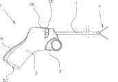
附图中,参考标号1表示腹腔镜仪器,该腹腔镜仪器包括具有扳机或可旋转致动器3的握柄2,当受外力作用时(未示出),致动器3绕轴4旋转,其中该致动器3通过联动机构5而连接至一种已知的管状元件7。该管状元件7的安置方法为自该握柄2突出。在该管状元件7的第一端部设有以针头钳形式存在的效应器9,该效应器9可用于如腹腔镜手术中。In the drawings,
该管状元件7可绕其纵轴线旋转。该旋转由安置于该握柄2上部的转轮15控制。该效应器9与该管状元件7共同旋转。The
该效应器9的钳夹通过弯曲的带有齿轮的棘齿条22及大致互补的带有齿轮的棘爪24组成的棘齿机构的驱动而锁固于指定位置。为清楚地说明,图2、4、6、7及8-11透视地表示以示出棘齿条22及棘爪24的整组齿。The jaws of the
在本示例性的实施例中,该所示的棘齿条22为该联动机构5的一个整合部分。In the exemplary embodiment, the illustrated
在第一端部,该棘爪24通过轴25而旋转地附接于该握柄2,且通过柔性元件28而旋转地与安置在握柄2上部的可移动连接开关26相连接。该柔性元件28附接于安置在该轴25与该棘爪第二自由端之间的附接点27上的棘爪24。At a first end, the
该管状元件7固接于该转轮15,且该效应器9旋转地固接于该管状元件7。通过旋转该轮15,所述管状元件7和效应器9将会以其本身已知的方式而相对于该握柄2旋转。The
在图1和图2中,该致动器3在外力作用下空载且处于完全打开的位置。通过以连接在联动机构5及该握柄2的一部分之间的弹簧35形式的偏压元件,通过联动机构5传递偏压力的方式作为作用在该致动器3上的压缩力,将该致动器3推进该位置且使其绕轴4旋转至其离该握柄可能最远的最初位置,该位置在下面称为关闭位置。当该致动器3关闭时,安置于该管状元件7的第一端部的该效应器9处于其完全打开的位置。本领域的普通技术人员可知,在可选的实施例中,当该致动器3关闭时,该效应器9可处于其完全关闭的位置。In Figures 1 and 2, the
该仪器1设有可调背部6,其示于图1-4中该仪器1的最突出位置。该背部6通过由锁固元件42组成的锁固部件40而锁固于该位置,该锁固元件42的第一端部旋转地连接于处于附接部44中的握柄2的一部分。该锁固元件42的第二端部设有爪形部件47,该爪形部件47和与该爪形部件47互补的几个(图示出五个)挡块48中的一个交叉抓握,该挡块48安置在该背部6的内底部且从该背部6的内底部突出。该锁固元件42通过弹簧部件50由该爪形部件47移动至施压于挡块48的方式而被施加偏压。在该背部6的希望调整中,调节钮52受到抵消弹簧50的作用力的力,从而将爪形部件47脱离挡块48。当爪形部件47脱离挡块48时,背部6通过突出于该背部的内部的偏压元件51而被偏压至最远位置且由握柄2内的反向元件53上的自由端部承压。The
图中所示的背部6通过安置于该握柄2顶部的旋转连接件55而旋转地连接在握柄2上。本领域的普通技术人员可知,该可调背部6的旋转点可设置于其它位置,如设置于该握柄2的底部,且该可调背部6可以设有几个可旋转部。The
在可选的实施例中(未示出),该仪器握柄的调节件也可以设置在握柄2的腹部或设置在一个或两个侧部。In an optional embodiment (not shown), the adjustment part of the instrument handle can also be arranged on the abdomen of the
图3及4所示的致动器3已被移动至其内部或开启的位置,该以针头钳形式设置的效应器9处于闭合位置。The
图5-7中所示的可调背部6充分地移动进该握柄2内,以使该握柄2处于其几乎最小突出程度的位置,且该致动器3和该背部6之间的距离将会接近以至近可能的最小,同样,该爪形部件47已移动至承受抓握最远的仅一个挡块48。该握柄2的背部6可固定在如图5和图4所示的位置间的多个中间位置。为使握柄2能够最适应外科医生的手的大小,这种可能性调节是重要的,因此该使用的舒适性是理想的。The
图5和图7所示的棘齿机构的连接开关26安置在臂部内且该棘爪24啮合于该棘齿条22。图5所示的致动器3处于其初始位置,而图7所示的致动器3已部分地移动至朝向其最里面的位置。由于该棘齿机构已通过与该棘齿条22的斜齿相啮合的该棘爪24的斜齿而开启,只要该棘齿机构是开启的,该致动器3便不能返回其初始位置。然而,通过超过由弹簧35施加的偏压力的反向驱动力的应用,该致动器3允许其本身被进一步推向其最里面的位置。由于该柔性元件28,通过从该被允许在从该棘爪突出的互补齿上滑动的棘齿条22上突出的斜齿,该棘齿条22可沿一个相对于该棘爪24的方向移动。这样,该效应器9可以安置于处于完全打开和完全闭合位置之间的几乎任何位置和安全组织中或夹紧血管中,而不会使该效应器9失控。对该致动器3进一步施力以进一步夹紧。The
该仪器的组成示于本示例性的实施例中,该联动机构5与该致动器3以及握柄2的铰接式连接可提供致动器3和效应器9间的非线性传输。该非线性传输表现出关于外科医生的臂力使用和效应器9以及包括效应器9的有效力的控制的非常重要的优点,该有效力由应用于致动器3的外力传送,当从该致动器3处于关闭位置直到其处于完全开启位置期间,该有效力不断地增加,其中该效应器9优选地关闭。这是因为该致动器3从关闭位置移动至完全开启位置时,致动器3的移动和效应器9的移动之间的传输减弱了。The composition of the instrument is shown in this exemplary embodiment, the articulated connection of the
图8-11所示为该棘齿机构及其通过柔性元件28而与该连接开关26相连接的放大图。图8为与图5所示相关联的状态描述。图9示出了当致动器3已移动至基本上完全开启的位置时仪器1的一部分的透视图。当该致动器3从如图8所示位置移动至图9所示的位置时,期间,该连接开关26处于开启位置,该棘齿条22的斜齿将会相对于该棘爪24的斜齿移动,期间,通过该柔性元件28的作用,该棘爪24偏压于该棘齿条22。作用在致动器3上的外力中止时或至少比弹簧35的偏压力小(如图7所示)时,该弹簧35会推进该棘齿机构的齿至完全啮合并锁固该效应器9以防止其移动至打开位置。8-11 show enlarged views of the ratchet mechanism and its connection with the
图10中,当棘爪24的齿仍与棘齿条22的齿相啮合时,该连接开关26已移动至关闭位置。在这种情况下,该柔性元件28处于稍微伸展的形态,从而使该棘爪24受向上的张紧力作用。然而,该产生于棘爪24与棘齿条22受力表面的齿之间的摩擦力会阻止棘爪24绕轴25顺时针旋转。为减小摩擦力,使用的方法为用该柔性元件28的张紧力将棘爪24拉离与棘齿条22的啮合,通过对该致动器3施加小压力或使其向里移动而减小各个齿之间的承压。然后,棘爪24的齿会被拉离与棘齿条22的齿的啮合,如图11所示。应注意图11中的棘齿条22需比棘爪24脱离棘齿条22移动的更远。In FIG. 10, when the teeth of the
该棘齿机构20的齿组的斜度取决于该连接开关26已移动至关闭位置之后,该弹簧35是否需要保持棘齿条22的齿组与棘爪24的齿组的啮合。在一些实施例中(未示出),这些齿不是倾斜的,一旦该连接开关26移动至关闭位置,齿间的啮合即会中止。通过致动器3,可以向相对于与棘齿条相啮合的棘爪的两个方向驱动棘齿条。The inclination of the tooth set of the ratchet mechanism 20 depends on whether the
本领域的普通技术人员可以理解,示于本示例性实施例中的带有所谓的闭合手指握柄的该致动器3可设有所谓的开口手指握柄。A person skilled in the art will appreciate that the
在可选的实施例(未示出)中,可移动连接开关26由已知类型的按压开关替换,优选地安置在握柄上部相对于在握柄周围的手指位置的自然位置。In an alternative embodiment (not shown), the
Claims (10)
Translated fromChineseApplications Claiming Priority (2)
| Application Number | Priority Date | Filing Date | Title |
|---|---|---|---|
| NO20045706 | 2004-12-29 | ||
| NO20045706ANO322695B1 (en) | 2004-12-29 | 2004-12-29 | Instrument especially for use in laparoscopic surgical procedure |
Publications (2)
| Publication Number | Publication Date |
|---|---|
| CN101090672A CN101090672A (en) | 2007-12-19 |
| CN100563585Ctrue CN100563585C (en) | 2009-12-02 |
Family
ID=35209726
Family Applications (1)
| Application Number | Title | Priority Date | Filing Date |
|---|---|---|---|
| CNB2005800450483AExpired - Fee RelatedCN100563585C (en) | 2004-12-29 | 2005-12-23 | Be particularly useful for the instrument of laparoscopic surgery |
Country Status (10)
| Country | Link |
|---|---|
| US (1) | US20090131974A1 (en) |
| EP (1) | EP1833389A1 (en) |
| JP (1) | JP4825221B2 (en) |
| KR (1) | KR20070109992A (en) |
| CN (1) | CN100563585C (en) |
| AU (1) | AU2005322693B2 (en) |
| CA (1) | CA2591210A1 (en) |
| NO (1) | NO322695B1 (en) |
| RU (1) | RU2397726C2 (en) |
| WO (1) | WO2006071120A1 (en) |
Families Citing this family (50)
| Publication number | Priority date | Publication date | Assignee | Title |
|---|---|---|---|---|
| NO322694B1 (en)* | 2004-12-29 | 2006-11-27 | Surgitech Norway As | Apparatus, especially for use in laparoscopic surgery |
| JP2009045428A (en) | 2007-07-25 | 2009-03-05 | Terumo Corp | Operating mechanism, medical manipulator and surgical robot system |
| CA2706860C (en) | 2007-11-26 | 2017-08-01 | Eastern Virginia Medical School | Magnaretractor system and method |
| DE102008017299A1 (en) | 2008-03-31 | 2009-10-01 | Karl Storz Gmbh & Co. Kg | Medical instrument with a ratchet |
| US8801752B2 (en)* | 2008-08-04 | 2014-08-12 | Covidien Lp | Articulating surgical device |
| CL2009000279A1 (en) | 2009-02-06 | 2009-08-14 | Biotech Innovations Ltda | Remote guidance and traction system for mini-invasive surgery, comprising: at least one surgical and removable endopinza with hooking means and a portion of ferro-magnaetic material, a cylindrical introduction guide, a detachment mechanism, and at least a means of remote traction with magnet. |
| DE102009018638A1 (en)* | 2009-04-17 | 2010-10-21 | Karl Storz Gmbh & Co. Kg | Medical instrument with a rotatable locking mechanism |
| EP2485662B1 (en)* | 2009-10-09 | 2015-09-09 | Applied Medical Resources Corporation | Single port instruments |
| DE102009055747A1 (en)* | 2009-11-26 | 2011-06-09 | Olympus Winter & Ibe Gmbh | Surgical forceps with grooving |
| USD642680S1 (en)* | 2010-05-07 | 2011-08-02 | Karl Storz Gmbh & Co. Kg | Thread guide for laparoscopic surgery |
| FR2968189A1 (en)* | 2010-12-02 | 2012-06-08 | Collin | Medical instrument for use during micro surgery of patient under vision of microscope, has actuating arm moved with respect to reference arm for actuating operating head, where reference arm has housing to receive finger of hand of user |
| EP2471473A1 (en) | 2010-12-29 | 2012-07-04 | Consorcio para la Gestion del Centro de Cirugia de Minima Invasion | Apparatus for laparoscopic surgery |
| US9039691B2 (en) | 2012-06-29 | 2015-05-26 | Covidien Lp | Surgical forceps |
| US9072524B2 (en) | 2012-06-29 | 2015-07-07 | Covidien Lp | Surgical forceps |
| US8764769B1 (en) | 2013-03-12 | 2014-07-01 | Levita Magnetics International Corp. | Grasper with magnetically-controlled positioning |
| US10010370B2 (en) | 2013-03-14 | 2018-07-03 | Levita Magnetics International Corp. | Magnetic control assemblies and systems therefor |
| US9597141B2 (en) | 2013-09-03 | 2017-03-21 | Covidien Lp | Switch assemblies for multi-function surgical instruments and surgical instruments incorporating the same |
| US9713492B2 (en) | 2013-09-03 | 2017-07-25 | Covidien Lp | Switch assemblies for multi-function surgical instruments and surgical instruments incorporating the same |
| US9579117B2 (en) | 2013-09-25 | 2017-02-28 | Covidien Lp | Multi-function surgical instruments |
| WO2015112645A1 (en) | 2014-01-21 | 2015-07-30 | Levita Magnetics International Corp. | Laparoscopic graspers and systems therefor |
| US10231776B2 (en) | 2014-01-29 | 2019-03-19 | Covidien Lp | Tissue sealing instrument with tissue-dissecting electrode |
| US10080605B2 (en) | 2014-09-17 | 2018-09-25 | Covidien Lp | Deployment mechanisms for surgical instruments |
| US9877777B2 (en) | 2014-09-17 | 2018-01-30 | Covidien Lp | Surgical instrument having a bipolar end effector assembly and a deployable monopolar assembly |
| US9918785B2 (en) | 2014-09-17 | 2018-03-20 | Covidien Lp | Deployment mechanisms for surgical instruments |
| US9987076B2 (en) | 2014-09-17 | 2018-06-05 | Covidien Lp | Multi-function surgical instruments |
| US10039592B2 (en) | 2014-09-17 | 2018-08-07 | Covidien Lp | Deployment mechanisms for surgical instruments |
| US9814517B2 (en) | 2014-11-17 | 2017-11-14 | Covidien Lp | Deployment mechanisms for multi-function surgical instruments |
| US9687294B2 (en) | 2014-11-17 | 2017-06-27 | Covidien Lp | Deployment mechanism for surgical instruments |
| US9814516B2 (en) | 2014-11-17 | 2017-11-14 | Covidien Lp | Deployment mechanisms for multi-function surgical instruments |
| US9724153B2 (en) | 2014-11-17 | 2017-08-08 | Covidien Lp | Deployment mechanisms for surgical instruments |
| US9867656B2 (en) | 2014-11-17 | 2018-01-16 | Covidien Lp | Multi-function surgical instruments |
| US9687293B2 (en) | 2014-11-17 | 2017-06-27 | Covidien Lp | Deployment mechanism for surgical instruments |
| US10478245B2 (en) | 2014-12-10 | 2019-11-19 | Covidien Lp | Energizable attachment for surgical devices |
| ES2895900T3 (en) | 2015-04-13 | 2022-02-23 | Levita Magnetics Int Corp | Magnetically controlled location handle |
| WO2016168377A1 (en) | 2015-04-13 | 2016-10-20 | Levita Magnetics International Corp. | Retractor systems, devices, and methods for use |
| USD844139S1 (en) | 2015-07-17 | 2019-03-26 | Covidien Lp | Monopolar assembly of a multi-function surgical instrument |
| USD844138S1 (en) | 2015-07-17 | 2019-03-26 | Covidien Lp | Handle assembly of a multi-function surgical instrument |
| EP3399902B1 (en) | 2016-01-08 | 2024-06-12 | Levita Magnetics International Corp. | One-operator surgical system |
| US10537381B2 (en) | 2016-02-26 | 2020-01-21 | Covidien Lp | Surgical instrument having a bipolar end effector assembly and a deployable monopolar assembly |
| JP6683368B2 (en)* | 2016-03-31 | 2020-04-22 | 国立大学法人鳥取大学 | Medical forceps |
| US11020137B2 (en) | 2017-03-20 | 2021-06-01 | Levita Magnetics International Corp. | Directable traction systems and methods |
| US11154348B2 (en) | 2017-08-29 | 2021-10-26 | Covidien Lp | Surgical instruments and methods of assembling surgical instruments |
| US10918393B2 (en) | 2017-11-05 | 2021-02-16 | Grena Usa Llc | Surgical appliance |
| US11123132B2 (en) | 2018-04-09 | 2021-09-21 | Covidien Lp | Multi-function surgical instruments and assemblies therefor |
| US10828756B2 (en) | 2018-04-24 | 2020-11-10 | Covidien Lp | Disassembly methods facilitating reprocessing of multi-function surgical instruments |
| US20190388074A1 (en)* | 2018-06-22 | 2019-12-26 | Boston Scientific Scimed, Inc. | Tissue removal devices and related methods |
| CN112353637A (en)* | 2020-11-02 | 2021-02-12 | 湖南哲能赫新能源有限责任公司 | Wrist joint bending and stretching exercise rehabilitation training device |
| KR102560361B1 (en)* | 2020-12-09 | 2023-07-27 | (주)이롭 | A medical grasper for decreasing fatigue of hand |
| US20240315717A1 (en)* | 2021-11-30 | 2024-09-26 | Public University Corporation Yokohama City University | Forceps device |
| US20250127506A1 (en)* | 2023-10-24 | 2025-04-24 | Astron Medtech Corporation | Surgical device |
Family Cites Families (34)
| Publication number | Priority date | Publication date | Assignee | Title |
|---|---|---|---|---|
| DE8418993U1 (en)* | 1984-06-23 | 1984-09-20 | Richard Wolf Gmbh, 7134 Knittlingen | Medical forceps |
| US4633869A (en)* | 1985-12-23 | 1987-01-06 | Arthrex Arthroscopy Instruments, Inc. | Tension retaining device for surgical procedures |
| US4963147A (en)* | 1987-09-18 | 1990-10-16 | John M. Agee | Surgical instrument |
| JP2545558Y2 (en)* | 1990-10-23 | 1997-08-25 | ジョンソン・エンド・ジョンソンメディカル株式会社 | Deep suture instrument |
| US5484441A (en)* | 1991-06-17 | 1996-01-16 | Koros; Tibor | Rongeur surgical instrument |
| CA2075319C (en)* | 1991-09-26 | 1998-06-30 | Ernie Aranyi | Handle for surgical instruments |
| AU3656993A (en)* | 1992-02-07 | 1993-09-03 | Symbiosis Corporation | Endoscopic surgical instruments having stepped rotatable end effectors |
| US5230704A (en)* | 1992-06-26 | 1993-07-27 | Biomedical Dynamics Corporation | Suction/irrigation instrument having reusable handle with disposable fluid path |
| US5607436A (en)* | 1993-10-08 | 1997-03-04 | United States Surgical Corporation | Apparatus for applying surgical clips |
| US5556416A (en)* | 1993-10-12 | 1996-09-17 | Valleylab, Inc. | Endoscopic instrument |
| US5484411A (en)* | 1994-01-14 | 1996-01-16 | Cordis Corporation | Spiral shaped perfusion balloon and method of use and manufacture |
| US5782749A (en)* | 1994-05-10 | 1998-07-21 | Riza; Erol D. | Laparoscopic surgical instrument with adjustable grip |
| US5609601A (en)* | 1994-09-23 | 1997-03-11 | United States Surgical Corporation | Endoscopic surgical apparatus with rotation lock |
| JP3780008B2 (en)* | 1994-12-15 | 2006-05-31 | テルモ株式会社 | Surgical instruments |
| US5632432A (en)* | 1994-12-19 | 1997-05-27 | Ethicon Endo-Surgery, Inc. | Surgical instrument |
| US5746760A (en)* | 1995-01-17 | 1998-05-05 | Laserscope | Semi-automatic tissue morcellation device |
| RU2127557C1 (en)* | 1995-01-30 | 1999-03-20 | Иркутский Государственный Медицинский Институт | Endoscopic surgical instrument |
| US5582615A (en)* | 1995-10-30 | 1996-12-10 | Pilling Weck, Incorporated | Handle for surgical clip applicator systems |
| WO1997024072A1 (en)* | 1995-12-29 | 1997-07-10 | Riza Erol D | Laparoscopic surgical instrument with adjustable grip |
| US5626608A (en)* | 1996-03-29 | 1997-05-06 | United States Surgical Corporation | Surgical instrument having locking handle |
| RU2117441C1 (en)* | 1996-08-05 | 1998-08-20 | Урбанюк Владимир Порфирьевич | Endoscopic surgical instrument |
| US5735873A (en)* | 1996-12-19 | 1998-04-07 | Maclean; David S. | Surgical tool handle |
| US5928252A (en)* | 1997-01-21 | 1999-07-27 | Regen Biologics, Inc. | Device and method for driving a needle and meniscal repair |
| US5830231A (en)* | 1997-03-19 | 1998-11-03 | Geiges, Jr.; John J. | Handle and actuating mechanism for surgical instruments |
| US5941439A (en)* | 1997-05-14 | 1999-08-24 | Mitek Surgical Products, Inc. | Applicator and method for deploying a surgical fastener in tissue |
| US6159207A (en)* | 1997-07-31 | 2000-12-12 | Yoon; Inbae | Protected ablation method and apparatus |
| JP3868111B2 (en)* | 1998-05-12 | 2007-01-17 | オリンパス株式会社 | Rigid forceps |
| DE19860444C2 (en)* | 1998-12-28 | 2001-03-29 | Storz Karl Gmbh & Co Kg | Handle for a medical tubular shaft instrument |
| US6419675B1 (en)* | 1999-09-03 | 2002-07-16 | Conmed Corporation | Electrosurgical coagulating and cutting instrument |
| US6471659B2 (en)* | 1999-12-27 | 2002-10-29 | Neothermia Corporation | Minimally invasive intact recovery of tissue |
| JP3996353B2 (en)* | 2001-02-28 | 2007-10-24 | 株式会社トップ | forceps |
| JP4632582B2 (en)* | 2001-07-02 | 2011-02-16 | 株式会社トップ | Surgical operation handle disassembly structure |
| JP3929021B2 (en)* | 2001-10-05 | 2007-06-13 | 株式会社トップ | forceps |
| US6944914B2 (en)* | 2001-10-24 | 2005-09-20 | Tillim Stephen L | Handle and forceps/tweezers and method and apparatus for designing the like |
- 2004
- 2004-12-29NONO20045706Apatent/NO322695B1/ennot_activeIP Right Cessation
- 2005
- 2005-12-23CNCNB2005800450483Apatent/CN100563585C/ennot_activeExpired - Fee Related
- 2005-12-23CACA002591210Apatent/CA2591210A1/ennot_activeAbandoned
- 2005-12-23EPEP05819376Apatent/EP1833389A1/ennot_activeWithdrawn
- 2005-12-23AUAU2005322693Apatent/AU2005322693B2/ennot_activeCeased
- 2005-12-23JPJP2007549295Apatent/JP4825221B2/ennot_activeExpired - Fee Related
- 2005-12-23WOPCT/NO2005/000478patent/WO2006071120A1/enactiveApplication Filing
- 2005-12-23USUS11/813,082patent/US20090131974A1/ennot_activeAbandoned
- 2005-12-23RURU2007126952/14Apatent/RU2397726C2/ennot_activeIP Right Cessation
- 2005-12-23KRKR1020077015371Apatent/KR20070109992A/ennot_activeCeased
Also Published As
| Publication number | Publication date |
|---|---|
| RU2007126952A (en) | 2009-02-10 |
| CA2591210A1 (en) | 2006-07-06 |
| NO20045706L (en) | 2006-06-30 |
| JP4825221B2 (en) | 2011-11-30 |
| AU2005322693A1 (en) | 2006-07-06 |
| JP2008525145A (en) | 2008-07-17 |
| KR20070109992A (en) | 2007-11-15 |
| RU2397726C2 (en) | 2010-08-27 |
| NO322695B1 (en) | 2006-11-27 |
| AU2005322693B2 (en) | 2009-07-16 |
| CN101090672A (en) | 2007-12-19 |
| EP1833389A1 (en) | 2007-09-19 |
| US20090131974A1 (en) | 2009-05-21 |
| WO2006071120A1 (en) | 2006-07-06 |
| NO20045706D0 (en) | 2004-12-29 |
Similar Documents
| Publication | Publication Date | Title |
|---|---|---|
| CN100563585C (en) | Be particularly useful for the instrument of laparoscopic surgery | |
| EP1815809B1 (en) | Handle for surgical instruments | |
| JP4364472B2 (en) | Laparoscopic forceps handle | |
| EP1872729B1 (en) | Medical instrument for grasping on object, in particular needle holder | |
| US5626608A (en) | Surgical instrument having locking handle | |
| US8512315B2 (en) | Surgical device | |
| US11627978B2 (en) | Surgical instrument with mechanically operable lever | |
| CA2843700A1 (en) | A surgical suture apparatus | |
| CN109662740B (en) | Surgical instrument | |
| RU2389443C2 (en) | Laparoscopic instrument | |
| JP6161790B2 (en) | Ergonomic locking mechanism | |
| JP3996353B2 (en) | forceps | |
| JP3922955B2 (en) | Surgical instrument | |
| EP3518723B1 (en) | A set comprising an endoscope and a work tool unit |
Legal Events
| Date | Code | Title | Description |
|---|---|---|---|
| C06 | Publication | ||
| PB01 | Publication | ||
| C10 | Entry into substantive examination | ||
| SE01 | Entry into force of request for substantive examination | ||
| C14 | Grant of patent or utility model | ||
| GR01 | Patent grant | ||
| C17 | Cessation of patent right | ||
| CF01 | Termination of patent right due to non-payment of annual fee | Granted publication date:20091202 Termination date:20111223 |