CN100561491C - Method and device for automatic path learning - Google Patents
Method and device for automatic path learningDownload PDFInfo
- Publication number
- CN100561491C CN100561491CCNB2006800057287ACN200680005728ACN100561491CCN 100561491 CCN100561491 CCN 100561491CCN B2006800057287 ACNB2006800057287 ACN B2006800057287ACN 200680005728 ACN200680005728 ACN 200680005728ACN 100561491 CCN100561491 CCN 100561491C
- Authority
- CN
- China
- Prior art keywords
- workpiece
- robot
- path
- tool holder
- points
- Prior art date
- Legal status (The legal status is an assumption and is not a legal conclusion. Google has not performed a legal analysis and makes no representation as to the accuracy of the status listed.)
- Active
Links
Images


Classifications
- G—PHYSICS
- G05—CONTROLLING; REGULATING
- G05B—CONTROL OR REGULATING SYSTEMS IN GENERAL; FUNCTIONAL ELEMENTS OF SUCH SYSTEMS; MONITORING OR TESTING ARRANGEMENTS FOR SUCH SYSTEMS OR ELEMENTS
- G05B19/00—Programme-control systems
- G05B19/02—Programme-control systems electric
- G05B19/42—Recording and playback systems, i.e. in which the programme is recorded from a cycle of operations, e.g. the cycle of operations being manually controlled, after which this record is played back on the same machine
- G05B19/423—Teaching successive positions by walk-through, i.e. the tool head or end effector being grasped and guided directly, with or without servo-assistance, to follow a path
- B—PERFORMING OPERATIONS; TRANSPORTING
- B25—HAND TOOLS; PORTABLE POWER-DRIVEN TOOLS; MANIPULATORS
- B25J—MANIPULATORS; CHAMBERS PROVIDED WITH MANIPULATION DEVICES
- B25J9/00—Programme-controlled manipulators
- B25J9/16—Programme controls
- B25J9/1656—Programme controls characterised by programming, planning systems for manipulators
- B25J9/1664—Programme controls characterised by programming, planning systems for manipulators characterised by motion, path, trajectory planning
- G—PHYSICS
- G05—CONTROLLING; REGULATING
- G05B—CONTROL OR REGULATING SYSTEMS IN GENERAL; FUNCTIONAL ELEMENTS OF SUCH SYSTEMS; MONITORING OR TESTING ARRANGEMENTS FOR SUCH SYSTEMS OR ELEMENTS
- G05B2219/00—Program-control systems
- G05B2219/30—Nc systems
- G05B2219/36—Nc in input of data, input key till input tape
- G05B2219/36404—Adapt teached position as function of deviation 3-D, 2-D position workpiece
- G—PHYSICS
- G05—CONTROLLING; REGULATING
- G05B—CONTROL OR REGULATING SYSTEMS IN GENERAL; FUNCTIONAL ELEMENTS OF SUCH SYSTEMS; MONITORING OR TESTING ARRANGEMENTS FOR SUCH SYSTEMS OR ELEMENTS
- G05B2219/00—Program-control systems
- G05B2219/30—Nc systems
- G05B2219/36—Nc in input of data, input key till input tape
- G05B2219/36409—Geometric adaptation by sensing force on surface of workpiece, object
- G—PHYSICS
- G05—CONTROLLING; REGULATING
- G05B—CONTROL OR REGULATING SYSTEMS IN GENERAL; FUNCTIONAL ELEMENTS OF SUCH SYSTEMS; MONITORING OR TESTING ARRANGEMENTS FOR SUCH SYSTEMS OR ELEMENTS
- G05B2219/00—Program-control systems
- G05B2219/30—Nc systems
- G05B2219/40—Robotics, robotics mapping to robotics vision
- G05B2219/40385—Compare offline teached point with online teached point, modify rest as function of error
Landscapes
- Engineering & Computer Science (AREA)
- Robotics (AREA)
- Mechanical Engineering (AREA)
- Physics & Mathematics (AREA)
- General Physics & Mathematics (AREA)
- Automation & Control Theory (AREA)
- Manipulator (AREA)
- Numerical Control (AREA)
Abstract
Translated fromChinese
Description
Translated fromChinese相关申请的交叉引用Cross References to Related Applications
本申请要求2005年2月24日提出、序列号为60/656435、名称为“自动机器人路径学习的方法”的美国临时专利申请的优先权,在此将上述申请的内容全部引入作为参考,并且由此要求35U.S.C.119(e)下的优先权利益。This application claims priority to U.S. Provisional Patent Application Serial No. 60/656435, entitled "Methods for Automatic Robotic Path Learning," filed February 24, 2005, the entire contents of which are hereby incorporated by reference, and Priority benefits under 35 U.S.C. 119(e) are hereby claimed.
技术领域technical field
本发明涉及机器人,更为具体地,涉及自动机器人运动编程的方法和设备。The present invention relates to robots, and more particularly, to methods and devices for automatic robot motion programming.
背景技术Background technique
可编程的机器人通常用于各种重复性的工业应用中。正如人们所理解的,机器人仅执行预先编程的任务和进行预先编程的运动。机器人运动的编程可能会是复杂且耗时的过程。降低编程时间的方法包括在真实设置的状态下通过教导加以引导以及在计算机模拟设置的状态下离线编程。通过教导加以引导的方法大致在美国专利4408286(“286号专利”)中得以揭示。Programmable robots are commonly used in a variety of repetitive industrial applications. As people understand, robots only perform pre-programmed tasks and perform pre-programmed movements. Programming robot motion can be a complex and time-consuming process. Methods to reduce programming time include guided by teaching in a real setup and off-line programming in a computer simulation setup. The method of leading by teaching is generally disclosed in US Patent 4,408,286 ("the '286 patent").
典型的通过教导加以引导的方法包括下述步骤:通过一系列所需的运动移动机器人,在机器人的移动过程中感测特定点,将所述特定点记录在微处理器中,并且使用所记录的点生成移动命令。机器人根据生成的移动命令而重复所需的运动。使用通过教导加以引导的方法对机器人编程的操作者能够在三维或者更多维上引导机器人并且维持机器人的所需位置和方向。传统的通过教导加以引导的方法的缺陷在于:操作者必须通过运动恒定地引导机器人,所述运动要符合通过所需运动精确地引导机器人的需要,同时不允许与工作区中的物体碰撞,并且不允许机器人对工件施加过度压力。A typical teach-by-guidance method includes the steps of moving the robot through a desired series of motions, sensing specific points during the robot's movement, recording the specific points in a microprocessor, and using the recorded A point generates a move command. The robot repeats the desired motion according to the generated movement commands. An operator who programs a robot using a guided-by-teach approach is able to guide the robot in three or more dimensions and maintain a desired position and orientation of the robot. A disadvantage of the conventional guidance-by-teaching method is that the operator must constantly guide the robot through a movement that corresponds to the need to guide the robot precisely through the desired movement, while not allowing collisions with objects in the workspace, and Do not allow the robot to exert excessive pressure on the workpiece.
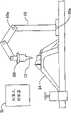
如图1所示,清理具有复杂轮廓的工件的毛刺的操作者能够容易地操纵手持的去毛刺工具或者抛光工具12,该工件例如为汽车部件14,该去毛刺工具或者抛光工具在图1中显示为与机器人10的末端执行器相连接。当相同的抛光工具12与机器人10的末端执行器相连接的时候,该任务对于操作者而言变得繁重,并且操作者对抛光工具12的直观移动变得困难,导致不太令人满意的机器人10编程移动。另外,如果去毛刺工具12意外地碰撞工件14,或者如果由于操作者未能克服机器人10的惯性力或者无法引导机器人10沿着所需路径运动,从而对工件14施加过度的压力,则工件12或者工具12可能会损坏。As shown in FIG. 1, an operator deburring a workpiece having a complex contour, such as an
现有技术中,对通过教导加以引导的方法的提高包括使用多种类型的教导手段(未示出),所述手段帮助操作者引导机器人进行所需的运动。教导手段强化了机器人方面操作者的机械优势,但是当维持三维或者多维控制的时候,操作者仍然需要操纵并且精确控制机器人进行所需的运动。2005年2月4日提出并且属于本发明受让人所有的序列号为11/051383的美国专利申请显示和描述了所述手段的一个示例。在第6385508号美国专利中显示和描述了所述手段的另一个示例。在第6285920号美国专利中描述但是没有示出一种手段,该专利描述了机器人的操纵杆微动。Advances in the prior art approach to guidance by teaching include the use of various types of teaching means (not shown) that assist the operator in guiding the robot to the desired motion. The teaching method strengthens the mechanical advantage of the operator in the robot, but when maintaining three-dimensional or multi-dimensional control, the operator still needs to manipulate and precisely control the robot to perform the desired movement. One example of such means is shown and described in US Patent Application Serial No. 11/051383, filed February 4, 2005 and owned by the assignee of the present invention. Another example of such means is shown and described in US Patent No. 6,385,508. One approach is described but not shown in US Patent No. 6,285,920, which describes joystick jogging of a robot.
离线编程方法需要满足下述条件:对于工件具有可用的计算机模型,并且具有可得的精确校准设备和过程来将模拟设置中的程序数据转换为机器人设置中的程序数据。因此,如果没有可用的计算机模型或者校准精确度不足以满足过程的需要,那么该方法不能够加以使用。The off-line programming approach requires the availability of a computer model of the workpiece and the availability of precisely calibrated equipment and procedures to convert program data in the simulation setup to program data in the robot setup. Therefore, this method cannot be used if no computer model is available or if the calibration accuracy is insufficient for the process.
因此,需要一种方法和设备,其使得操作者在实际设置中花费最小的努力就能够对机器人的运动进行编程,从而过程需要和移动路径一起得以提出,并且对于机器人进行编程中的任何特殊情况,操作者能够提供在现场及时进行判断。另外,希望在不加重操作者负担的情况下,恒定地维持机器人和工件之间的空间关系。而且,还希望甚至在必须进行近距离接触的应用中,机器人和工件仍然不会发生碰撞。另外,期望在编程操作中,操作者不必针对复杂路径中的所有编程点在三维方向上引导机器人,以降低机器人所需运动编程的复杂性。还有,教导操作的简化使得效率可以更高,并允许对机器人运动进行自动化的教导,使得小批量作业的可编程机器人的频繁编程经济可行。Therefore, there is a need for a method and apparatus that enables the operator to program the motion of the robot with minimal effort in the actual set-up, so that the process needs are addressed together with the path of movement, and for any special case in the programming of the robot , the operator can provide timely judgment on the spot. In addition, it is desirable to constantly maintain the spatial relationship between the robot and the workpiece without imposing a burden on the operator. Furthermore, it is also desirable that even in applications where close contact is necessary, the robot and workpiece will still not collide. In addition, it is desirable that during programming operations, the operator does not have to guide the robot in three dimensions for all programmed points in a complex path, in order to reduce the complexity of programming the required motion of the robot. Also, the simplification of the teaching operation allows for higher efficiency and allows automated teaching of robot motion, making frequent programming of programmable robots for small batches economically feasible.
正如下面将要详细描述的,本发明允许操作者首先对机器人教导如下内容:机器人夹具(fixture)和工件之间的粗略空间关系(gross spatialrelationship),该关系在下文中称为导引点,并且允许机器人在机器人控制器的控制下沿着控制器根据导引点确定的路径运动,并且使用力控制来更新导引点并且还使用力控制学习位于相邻的导引点之间的一个或者多个点从而对于当机器人用于在工件上执行所需操作时机器人将遵循的路径生成程序。举例而言,所述所需操作可以是但不限于去毛刺、抛光或者打蘑。As will be described in detail below, the present invention allows the operator to first teach the robot the gross spatial relationship between the robot fixture and the workpiece, which is hereinafter referred to as the guide point, and allows the robot to Under the control of the robot controller, move along the path determined by the controller according to the guide points, and use force control to update the guide points and also use force control to learn one or more points between adjacent guide points A program is thereby generated for the path the robot will follow when it is used to perform the desired operation on the workpiece. For example, the desired operation may be, but not limited to, deburring, polishing, or mushrooming.
导引点的离线教导由Frederick Proctor Proceedings Of TheInternational Manufacturing Technology Forum,Chicago,IL,June 4-5,1992的“高级制造中的控制传感器(Control Sensors For AdvancedManufacturing)”提出。然而,Proctor没有教导使用力控制来学习与导引点相邻且位于其中间的一个或者多个点。国际公布PCT申请WO94/20262教导在工件的机器加工过程中,使用导引点和力控制,但是与Proctor的情况一样没有教导在机器人用于在工件上执行所需操作之前,使用力控制学习与导引点相邻且位于其中间的一个或者多个点。Offline teaching of pilot points was proposed by Frederick Proctor Proceedings Of The International Manufacturing Technology Forum, Chicago, IL, June 4-5, 1992, "Control Sensors For Advanced Manufacturing". However, Proctor does not teach the use of force control to learn one or more points adjacent to and in between a guide point. International Published PCT Application WO94/20262 teaches the use of guide points and force control during machining of workpieces, but as in the case of Proctor, does not teach the use of force control to learn and One or more points that are adjacent to and between leading points.
发明内容Contents of the invention
一种对机器人进行编程的方法,所述机器人具有力传感器、真实的或者有形的(tangible)工具夹具和控制器,该工具夹具用于与具有已知轮廓的工件配合工作,所述方法包括:A method of programming a robot having force sensors, a real or tangible tool holder for working with a workpiece having a known profile, and a controller, the method comprising:
提供所述工具夹具和所述工件轮廓之间的多个粗略空间关系;providing a plurality of rough spatial relationships between the tool holder and the workpiece profile;
限定所述工具夹具相对于所述工件轮廓的移动的第一路径,所述第一路径包括所述粗略空间关系;defining a first path of movement of the tool holder relative to the workpiece profile, the first path including the rough spatial relationship;
使用所述第一路径作为引导来移动所述工具夹具;moving the tool holder using the first path as a guide;
使用所述力传感器来确定所述移动的工具夹具是否与所述工件轮廓相接触;using the force sensor to determine whether the moving tool holder is in contact with the workpiece contour;
当所述移动的工具夹具与所述工件轮廓不接触的时候,使用所述控制器改变所述移动的工具夹具的方向,以使得所述工具夹具与所述工件轮廓相接触;changing the direction of the moving toolholder using the controller such that the toolholder is in contact with the workpiece contour when the moving toolholder is not in contact with the workpiece contour;
在所述粗略空间关系中间,收集工件轮廓上的、所述工具夹具接触所述工件轮廓的点处所述工具夹具和所述工件轮廓之间的空间关系;和Among the coarse spatial relationships, collecting a spatial relationship between the tool holder and the workpiece contour at points on the workpiece contour at which the tool holder contacts the workpiece contour; and
使用所收集到的空间关系限定所述工具夹具相对于所述工件的运动的第二路径。A second path of movement of the tool holder relative to the workpiece is defined using the collected spatial relationships.
一种对机器人进行编程的计算机程序产品,所述机器人具有力传感器、真实的或者有形的工具夹具和控制器,该工具夹具用于与具有已知轮廓的工件配合工作,所述计算机程序产品包括:A computer program product for programming a robot having force sensors, a real or tangible tool grip for working with a workpiece having a known profile, and a controller, the computer program product comprising :
计算机可读的程序代码,其配置为用于记录所述工具夹具和所述工件轮廓之间的多个粗略空间关系;computer readable program code configured to record a plurality of rough spatial relationships between the tool holder and the workpiece profile;
计算机可读的程序代码,其配置为用于基于所述工具夹具和所述工件轮廓之间的所述多个粗略空间关系而限定所述工具夹具相对于所述工件轮廓的运动的第一路径,所述第一路径包括所述粗略空间关系;computer readable program code configured to define a first path of motion of the tool holder relative to the workpiece contour based on the plurality of rough spatial relationships between the tool holder and the workpiece contour , the first path includes the rough spatial relationship;
计算机可读的程序代码,其配置为用于用所述第一路径作为引导而移动所述工具夹具;computer readable program code configured to move the tool holder using the first path as a guide;
计算机可读的程序代码,其配置为用于使用所述力传感器来确定所述移动的工具夹具是否与所述工件轮廓相接触;computer readable program code configured to determine whether the moving tool holder is in contact with the workpiece contour using the force sensor;
计算机可读的程序代码,其配置为用于当所述移动工具夹具与所述工件轮廓不接触时,使用所述控制器改变所述移动的工具夹具的方向,以使得所述工具夹具与所述工件轮廓相接触;computer readable program code configured to, using the controller, change the direction of the moving tool holder when the moving tool holder is out of contact with the workpiece contour such that the tool holder is in contact with the workpiece contact with the workpiece contour;
计算机可读的程序代码,其配置为:在所述粗略空间关系中间,收集工件轮廓上的、所述工具夹具接触所述工件轮廓的点处所述工具夹具和所述工件轮廓之间的空间关系;和computer readable program code configured to, intermediate the rough spatial relationship, collect a space between the tool holder and the workpiece outline at a point on the workpiece outline where the tool holder contacts the workpiece outline relationship; and
计算机可读的程序代码,其配置为用于使用所记录的空间关系限定所述工具夹具相对于所述工件的运动的第二路径。Computer readable program code configured to define a second path of movement of the tool holder relative to the workpiece using the recorded spatial relationship.
一种对机器人进行编程的系统,所述机器人具有力传感器、真实的或者有形的工具夹具和控制器,该控制器用于与具有已知轮廓的工件配合工作,所述系统包括:A system for programming a robot having force sensors, a real or tangible tool grip and a controller for working with a workpiece having a known profile, the system comprising:
计算装置,该计算装置中具有能够由所述计算装置使用的程序代码,所述程序代码配置为用于:A computing device having therein program code usable by said computing device, said program code being configured to:
收集所述工具夹具和所述工件轮廓之间的多个粗略空间关系;collecting a plurality of rough spatial relationships between the tool holder and the workpiece profile;
基于所述工具夹具和所述工件轮廓之间的所述多个粗略空间关系,限定所述工具夹具相对于所述工件轮廓的移动的第一路径,所述第一路径包括所述粗略空间关系;defining a first path of movement of the toolholder relative to the workpiece contour based on the plurality of rough spatial relationships between the toolholder and the workpiece contour, the first path including the rough spatial relationships ;
用所述第一路径作为引导来移动所述工具夹具;moving the tool holder using the first path as a guide;
使用所述力传感器来确定所述移动的工具夹具是否与所述工件轮廓相接触;using the force sensor to determine whether the moving tool holder is in contact with the workpiece contour;
当所述移动的工具夹具与所述工件轮廓不接触的时候,使用所述控制器改变所述移动工具夹具的方向,以使得所述工具夹具与所述工件轮廓相接触;changing the direction of the moving toolholder using the controller such that the toolholder is in contact with the workpiece contour when the moving toolholder is out of contact with the workpiece contour;
在所述粗略空间关系中间,收集工件轮廓上的、所述工具夹具接触所述工件轮廓的点处所述工具夹具和所述工件轮廓之间的空间关系;和Among the coarse spatial relationships, collecting a spatial relationship between the tool holder and the workpiece contour at points on the workpiece contour at which the tool holder contacts the workpiece contour; and
使用所记录的空间关系来限定所述工具夹具相对于所述工件的运动的第二路径。A second path of movement of the tool holder relative to the workpiece is defined using the recorded spatial relationship.
附图说明Description of drawings
图1示出包括用于与工件配合的工具夹具的机器人。Figure 1 shows a robot including a tool holder for cooperating with a workpiece.
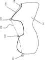
图2示出用于去毛刺应用中的路径示例。Figure 2 shows an example of a path used in a deburring application.
图3示出机器人如何被教导图2中的路径。Fig. 3 shows how the robot is taught the path in Fig. 2 .
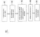
图4示出根据本发明的方法的流程图。FIG. 4 shows a flow chart of the method according to the invention.
图5示出工件和工具夹具的另一示例。Figure 5 shows another example of a workpiece and tool holder.
图6示出后处理算法的示例,该后处理算法用于处理所记录的机器人夹具相对于工件的空间关系。Figure 6 shows an example of a post-processing algorithm for processing the recorded spatial relationship of the robotic gripper relative to the workpiece.
具体实施方式Detailed ways
根据附图--其中相同编号在数个视图中标识类似或者相应的部分,一种用于对机器人进行编程的方法和设备得以公开。如图1所示,机器人10包括用于和工件14配合的工具夹具12、至少一个力传感器20、以及至少一个由机器人控制器11控制的电动机10a。用于和工件14配合的工具夹具12可以包括任何本领域公知类型的工具。该工具的示例包括去毛刺工具端、水射流割嘴、激光割嘴、焊嘴、抛光轮等。With reference to the drawings - wherein like numerals identify like or corresponding parts throughout the several views, a method and apparatus for programming a robot are disclosed. As shown in FIG. 1 , the
执行本发明方法的软件存储在控制器11中,并且可以从计算机可读介质加载到控制器11中,该计算机可读介质包括但不限于CD-ROM或者闪存驱动器,或者以其它公知方式实现,举例而言所述公知方式例如是将控制器11连接到局域网或者因特网,并且从控制器11所位于的站点或者从远离控制器11所在站点的另一个站点下载软件。正如本领域技术人员所公知的,执行本发明的方法的软件也可以存储在与机器人10交互的、不同于控制器11的计算装置(未示出)上。可以使用包含但不限于上述技术的多种公知技术中的任何一种将该软件加载到计算装置中。The software executing the method of the present invention is stored in the
本发明的自动路径学习可以用于许多不同过程。所述过程的一个示例是如图2所示的去毛刺应用,其需要对具有不规则轮廓的复杂路径141进行编程。该过程要求:在不切入部件的情况下,使用铣切销将在前面的处理(例如该部件的浇铸)中以毛刺或者毛边的形式留在部件主体或者工件14上的多余材料从部件主体14移除。现有技术和当前实践中需要机器人编程者教导机器人10许多点,以及从而教导控制器11许多点,以获得精确路径而复制工件14的精确外形或者轮廓141,在去毛刺或者其它过程中所述点可能数以百计。The automatic path learning of the present invention can be used in many different processes. An example of such a process is a deburring application as shown in Figure 2, which requires programming a
如图2所示,本发明的方法首先教导一些导引点151、152、153和154,这些点通常代表工件14轮廓的急剧变化。正如图2所示,在导引点151和152处,所述导引点不需要物理地位于工件14上。换句话说,去毛刺工具端不需要接触工件14。然而,下述内容通常是需要的,但不是必需的,即工具12相对于工件14位于与实际过程中相同的优选方向上。As shown in FIG. 2 , the method of the present invention first teaches a number of pilot points 151 , 152 , 153 and 154 , which generally represent sharp changes in the contour of the
可以使用多种方法中的任意一种教导导引点151-154,所述多种方法包括传统的远程操纵杆微动或者键控微动。优选方法是通过教导加以引导。引导式机器人编程大体上在286号专利中加以揭示。该编程方法与上面描述的教导的墨守陈规方法不同,在墨守陈规的方法中通过使用机器人教导的墨守陈规方法而使得机器人沿着编程运动路径运动。更确切地,通过教导加以引导使用图1中的附接至机器人末端执行器力传感器20来移动机器人10使之经过编程路径上的点。如上所述,在286号专利之后公开了一些通过教导加以引导的方法和用以通过教导加以引导的处理组件。The guidance points 151-154 may be taught using any of a number of methods including conventional remote joystick jogging or keyed jogging. The preferred method is to lead by teaching. Guided robot programming is generally disclosed in the '286 patent. This programmed method differs from the traditional method of teaching described above, in which the robot is caused to move along a programmed motion path by using the robotic method of teaching. Rather, the
接着,基于导引点151-154的线段,在机器人控制器11中生成基础的机器人程序,产生程序路径150。如图2所示,在控制器11中生成的用于工件14的程序路径150与实际轮廓141有很大差别。如果工具夹具12遵循程序路径150,其或者会如路径150的点151和152之间部分所示移入部件14,或者会如点路径150的152和153之间部分所示过于远离工件14,这两种情形都不是我们所期望的。Next, based on the line segments of the guide points 151-154, a basic robot program is generated in the
正如下面详细描述的,由于使用适应性运动模式,即力控制,所以本发明的方法防止上述情况发生,以允许工具夹具12在控制器11的控制下使用程序路径150来确定工具夹具12相对于工件轮廓141的方向,从而使得工具夹具沿着轮廓141而教导轮廓上的位于导引点151-154之间并且与之邻近一个或者多个点。另外,如果工件试图沿着路径150的导引点151和152之间部分,由于缺乏力控制,所以力控制使得工具夹具12不会撞击工件14;或者在工件沿着导引点151和152之间的路径150的时候使得工具夹具12临近工件14。As described in detail below, the method of the present invention prevents this from occurring due to the use of an adaptive motion mode, force control, to allow the
参考图3,为了清楚地解释该特定示例,在图中示出路径坐标系统Xp、Yp。该路径方向被称为Xp方向。当机器人10被编程沿着路径150运动时,机器人控制器11处于适应性运动模式,从而仅仅在Yp方向上的机器人运动是力控制的,该Yp方向与路径方向Xp垂直,所有其它方向和朝向仍然处于位置控制之下。因此,可以理解,尽管机器人10被编程为在中间点的教导过程中执行路径150,但是机器人将偏离路径150,并且,如下所述,因为控制器11处于适应性运动模式,所以机器人将遵循工件14的轮廓141。Referring to Figure 3, in order to clearly explain this particular example, the path coordinate system Xp, Yp is shown in the figure. This path direction is called the Xp direction. When the
另外,在控制器11中下述内容得以指明,该内容就是在Yp方向上维持恒定接触力(例如20牛顿)。由于该限制,如果程序路径150位于实际的工件轮廓中,如点155所示,则工具端将沿着Yp轴变形直到达到20牛顿的平衡,产生物理上位于工件轮廓上的新点255。在另一方面,如果程序路径150远离工件14,如点156的情况,则控制器将使得工具端更接近工件14,直到达到20N的平衡,产生新点256。从而,应当理解要不是适应性压力模式,工具夹具12会遵循路径150。如果工具夹具12沿着路径150,当工具夹具12试图沿着150路径的点151和152之间部分运动的时候,工具夹具12将撞到工件14;当工具固定端12沿着路径150的点152和153之间部分运动的时候,工具夹具12将过于远离轮廓141。适应性压力模式的使用确保所述情况不会发生,并且确保工具夹具12沿着轮廓141来学习中间点,举例而言例如图3中的中间点255和256。In addition, it is specified in the
如上所述,在教导轮廓141上的中间点的过程中,夹持工具夹具12的机器人10以适应性运动模式沿着工件轮廓141运动。在该教导的过程中,持续记录地实际的机器人方向和朝向。如上所述工具端总是与工件14持续接触,使得所记录的空间关系是工具夹具12和工件14之间位置关系的精确复制,并且使得基于记录路径产生的机器人程序能够直接用于执行实际操作。当机器人10执行实际操作的时候,机器人控制器11不需要使用任何力控制行为,除非该控制对于操作有利。As described above, during the teaching of intermediate points on the
应当理解上述新点255和256是工件14的轮廓上的与导引点临近并且位于导引点之间的示例。应当进一步理解,中间点255和256并非以上与图2相关所述的那样被教导到机器人10上,而是使用本发明的方法由机器人学习。因此,本发明的方法具有第一步骤和第二步骤,凭借第一步骤机器人10被教导一些例如点151-154的导引点;凭借第二步骤机器人控制器11使得机器人工具夹具12使用以导引点151-154确定的路径150引导工具夹具12朝向工件14,并且使用力控制最终确定导引点和一个或者多个与导引点临近的并且位于导引点之间的点,从而确定当工具夹具12执行工件14上的所需操作的时候工具夹具12所需要遵循的路径。It should be understood that the above-described
有时期望具有但不是必须具有采用后处理算法形式的后处理步骤,该后处理算法对连续记录的空间关系进行处理,所述空间关系在每个相邻点之间的恒定距离(例如2毫米)上方便地加以记录。本领域技术人员能够理解,在曲率缓慢变化的轮廓中,具有较大点间距离的点是可以接受的;但是在曲率急剧变化的轮廓中,密集的点仍是必要的。在后处理步骤之后,能够生成具有较少程序数据的更为有效的程序以用于生产。It is sometimes desirable, but not necessary, to have a post-processing step in the form of a post-processing algorithm that operates on successively recorded spatial relationships at a constant distance (e.g. 2mm) between each adjacent point record easily. Those skilled in the art can understand that in contours with slowly changing curvature, points with a larger distance between points are acceptable; but in contours with sharply changing curvature, dense points are still necessary. After the post-processing step, a more efficient program with less program data can be generated for production.
后处理算法是连续记录路径的进一步改善。实践中,连续记录的路径是时间取样的,其能够产生数千个点。举例而言,如果时间取样每4微秒进行一次并且机器人以4毫米/秒的速度运动,那么每秒记录1000个点或者每4mm记录1000个点。该记录的点就是此处描述的“中间点”。该大量点带来了机器人工具夹具12相对于工作间14的空间关系的较高精确度,然而在工件的轮廓不是那么剧烈地变化的情况下,这是资源的浪费。后处理算法通过移除不必要中间点的方式智能地处理大量点,从而最终路径即具有足够精确的细节又具有最小数量的点。The post-processing algorithm is a further improvement of the continuous recording path. In practice, the continuously recorded paths are time-sampled, which can generate thousands of points. For example, if time sampling is done every 4 microseconds and the robot is moving at 4 mm/s, then 1000 points are recorded per second or 1000 points are recorded every 4 mm. This recorded point is the "intermediate point" described here. This large number of points results in a higher accuracy of the spatial relationship of the
该后处理算法的一个示例在下面参考图6加以描述。该算法通过根据一系列用户限定的标准将实时短线段融合到一个较长线段以执行后处理。An example of this post-processing algorithm is described below with reference to FIG. 6 . The algorithm performs post-processing by fusing real-time short line segments into a longer line segment according to a series of user-defined criteria.
在该算法中,图6的路径点缓冲器60被设置以从实时位置记录函数中获得输入路径点。每当位置记录函数将新点(图6中的点14)压入到缓冲器60中的时候,后处理启动以扫描缓冲器60并且试图将短线段合并成一个较长线段。正如人们所理解的,在路径学习过程中,合并的线段(图6上部的点1-4)和未合并的线段(图6下部的点4-14)共存于缓冲器60中。后处理仅仅处理未合并的线段(点4-14)。In this algorithm, the
该算法根据算法用户限定的路径准确度参数检查是否可以由未合并的点4到14形成两个或者多个长线段。形成两个或者多个长线段的决定可以通过下述方式实现,该方式就是验证每个未合并点(点4到点14)到线62的距离,其中线62连接第一个未合并点(点4)和最后一个未合并点(点14)。如果存在大于路径准确度参数的距离,那么如图6的下部所示通过删除第一个未合并点(在该示例中是点4)和转折点(在该示例中是点13)之间的所有点的方式,执行合并。转折点被限定为距离高于路径准确度参数的情况的各个第一点。The algorithm checks whether two or more long line segments can be formed from the
后处理也可以用于校正学习的位置和方向。这种情况通常发生在高要求的应用中,该高要求的应用例如电弧焊,在该情况下需要设定工具的姿势以维持与路径之间的固定位置关系。Post-processing can also be used to correct the learned position and orientation. This typically occurs in demanding applications, such as arc welding, where the pose of the tool needs to be set to maintain a fixed positional relationship to the path.
对于多数处理而言,例如使用铣刀去毛刺处理,通常需要该工具维持与工作表面之间的特定角度。当操作者确定每个教导的导引点所需要的角度的时候,在教导导引点的同时该要求首先得以实现。这就是通过编程方法加以引导更为直接和便利的地方。当机器人处于适应性连续运动中的时候,在这种情况下机器人使用适应性力控制以确定导引点并且会教导一个或者多个且如上所述可能数千个的中间点,由于机器人的方向仍然处于闭环位置控制中,该预期角度仍然得以维持。当两个导引点之间的所需角度不同的时候,所有现存的工业机器人控制器会提供两点之间的内插值方向,这在适应性路径学习步骤中得以维持。如上所述,整套适应性路径学习是机器人使用适应性力控制确定导引点并且教导一个或者多个并且可能数千个的中间点,实现了两个特别的导引点之间的连续并且平滑的转换。For most processes, such as deburring with milling cutters, it is generally required that the tool maintain a certain angle to the work surface. When the operator determines the required angle for each taught pilot point, that requirement is first fulfilled while teaching the pilot point. This is where being guided programmatically is more straightforward and convenient. When the robot is in adaptive continuous motion, in which case the robot uses adaptive force control to determine the guidance point and will teach one or more, and as mentioned above potentially thousands of intermediate points, due to the orientation of the robot Still in closed loop position control, the desired angle is still maintained. When the desired angle between two guidance points is different, all existing industrial robot controllers provide an interpolated direction between two points, which is maintained during the adaptive path learning step. As mentioned above, the whole set of adaptive path learning is that the robot uses adaptive force control to determine the guidance point and teach one or more and possibly thousands of intermediate points, achieving a continuous and smooth transition between two particular guidance points conversion.
为了利于上述编程过程,具有与真实处理工具相同导引尺寸的人工有形工具(artificially tangible tool)通常是所需的。举例而言,在使用端铣刀去毛刺过程中,沿着工件表面移动具有锐利切削边缘的工具,会产生不合需要的部分表面的摩擦和损坏。然而,具有圆柱形状的人工有形工具解决了这个问题并且极大地提高了编程经验,该人工有形工具具有与真实工具相同的尺寸。To facilitate the programming process described above, an artificially tangible tool (artificially tangible tool) having the same guide dimensions as a real processing tool is usually required. For example, during deburring with an end mill, moving a tool with a sharp cutting edge along the surface of a workpiece can cause friction and damage to undesired portions of the surface. However, an artificial tangible tool with a cylindrical shape, which has the same dimensions as the real tool, solves this problem and greatly improves the programming experience.
参考图4,其是本发明方法的流程图40。该方法开始于42,在42处教导机器人夹具12和工件14之间的一些选出的引导空间关系,该引导空间关系是例如图2中所示的点151-154的导引点。能够借助通过教导加以引导、人工地缓动所述机器人或者从计算机模型获得所述导引点。该方法接着到达44处,在44处处理器11或者其它计算装置基于教导的导引点生成计算机程序。该方法接着进行到46处,在46处,当机器人10在适于特定处理的方向上处于适应性力控制下的时候,在机器人的持续运动中基于教导的粗略导引点执行在44处生成的程序,从而工具夹具12总是接触工件14并且沿着工件14的所需轮廓141。在48处,该方法连续记录在处于适应性力控制下的机器人的运动过程中机器人夹具12相对于工件14的空间关系和每个教导的中间点。在50处,该方法生成基于记录的空间关系和每个教导的中间点的机器人运动程序,其是给定的设置中实际需要的程序。尽管在图4中没有示出,本发明的方法还可以包括上述预定程序的后处理。Referring to FIG. 4 , it is a
本发明的方法在下述方面是唯一的,即其在适应性力控制下使用机器人的接触特性,从而机器人10的运动遵循编程确定的处理路径。在该过程中,操作者仅仅参与了教导机器人10的粗略运动的第一步骤,而大批步骤在机器人控制器11的控制下自动执行。The method of the present invention is unique in that it uses the contact properties of the robot under adaptive force control so that the motion of the
容易意识到,在处理单元中运行的时候,图4中所示的步骤适于由计算机程序执行,该计算机程序具有与该方法的步骤相对应的指令。优选地,计算机程序可以在机器人控制系统中的处理器上运行。It is readily appreciated that the steps shown in Fig. 4 are adapted to be performed by a computer program having instructions corresponding to the steps of the method, when run in a processing unit. Preferably, the computer program is runnable on a processor in the robot control system.
图5显示了工件14和处理工件的工具12。显示在图中的坐标系统是工具坐标系统XT、YT、ZT,其中ZT垂直于工件表面并且XT、YT垂直于ZT。RxT绕XT轴的旋转并且RyT是绕YT轴的旋转。Figure 5 shows a
应当理解,对于对机器人进行教导和编程而言,尤其是对于例如去毛刺处理的下述应用和处理而言,在该应用和处理中工具夹具和工件之间的接触是必须的,本发明能够节省巨大的时间和金钱成本。进行很少的改变,相同的编程原则可以容易地应用于例如研磨处理或者切割处理的其它处理中,在该过程中工具相对于切削平面的方向的调整十分重要。接着可以理解在这种情况下在ZT、RxT、RyT的方向/朝向上采用适应性力控制以实现表面对准整,如图5所示,从而工具/表面方向能够简便地获得。It will be appreciated that for teaching and programming a robot, especially for applications and processes such as deburring processes in which contact between the tool holder and workpiece is necessary, the present invention enables Save huge time and money cost. With few changes, the same programming principles can be easily applied to other processes such as grinding processes or cutting processes where the orientation of the tool relative to the cutting plane is important. It can then be understood that in this case adaptive force control is used in the direction/orientation of ZT , RxT , RyT to achieve surface alignment as shown in Figure 5 so that the tool/surface orientation can be easily obtained.
总之,本发明旨在实现下述内容:在仅仅教导一些简单的导引点的同时,使用力控制对轨线目标进行编程。现有技术的解决方案是曲率跟踪(curvature tracking)。该技术对于表面编程是可行的,但是是较慢的方法,其需要操作者进行大量工作以限定在表面上何处需要进行跟踪,并且限定如何处理不连续以及表面粗略。In summary, the present invention aims to achieve the following: programming trajectory targets using force control while only teaching a few simple guide points. A state-of-the-art solution is curvature tracking. This technique is feasible for surface programming, but is a slower method that requires a lot of work by the operator to define where on the surface tracking needs to be done, and to define how discontinuities and surface roughness are to be handled.
本发明的方法也可以采用CAD(计算机辅助设计)方法实现下述内容:对合适的点进行离线编程用于目标坐标系统编程;沿着表面或者边的导引点的限定(意味着导引点的相互教导是不需要的)--轨线相对于该表面或者边限定;以及沿着用于微调的轨线的力方向的限定。The method of the present invention can also adopt CAD (Computer Aided Design) method to realize following contents: suitable point is carried out off-line programming for target coordinate system programming; Mutual teaching of is not required)-the definition of the trajectory relative to the surface or edge; and the definition of the direction of force along the trajectory for fine-tuning.
能够理解,本发明使得操作者可以在真实设置的情况下以最少的付出对机器人的运动进行编程,从而处理要求和运动路径一起得出,并且在对机器人编程的过程中操作者对于任何特殊情况能够提供实地实时的判断。进一步能够理解本发明实现了持久地维护机器人和工件之间的空间关系而不给操作者增加维护该关系的负担。It will be appreciated that the present invention enables the operator to program the motion of the robot with minimal effort in a real setup, whereby the processing requirements are derived together with the motion paths, and the operator is not aware of any special circumstances during the programming of the robot. Can provide real-time judgment on the spot. It can further be appreciated that the present invention enables permanent maintenance of the spatial relationship between the robot and workpiece without burdening the operator with maintaining the relationship.
能够进一步理解,甚至在必须密切接触是情形下,本发明也能够防止机器人和工件碰撞。还能够理解,本发明使得操作者无须在编程操作过程中针对所有编程点在复杂路径上三维地引导机器人,以降低对机器人所需运动进行编程的复杂度。It can be further understood that the present invention can prevent the robot and the workpiece from colliding even in situations where close contact is necessary. It can also be appreciated that the present invention reduces the complexity of programming the desired motion of the robot by eliminating the need for the operator to three-dimensionally guide the robot on complex paths for all programmed points during programming operations.
本发明提出的教导操作的简化实现了机器人运动的更为便利并且自动的教导,使得对可编程机器人进行频繁编程用于小批量作业变得经济易行。The simplification of the teaching operation proposed by the present invention realizes more convenient and automatic teaching of the robot movement, making it economical and easy to frequently program the programmable robot for small batch operations.
能够理解前述示例性实施例的描述仅仅对本发明的示例性描述,而非对本发明的穷尽列举。在不脱离本发明的精神或者权利要求中界定的范围的前提下,本领域技术人员能够对所公开的实施例进行某些增加、删除和/或改变。It can be understood that the foregoing description of the exemplary embodiments is only an exemplary description of the present invention, rather than an exhaustive enumeration of the present invention. Those skilled in the art can make certain additions, deletions and/or changes to the disclosed embodiments without departing from the spirit of the invention or the scope defined in the claims.
Claims (8)
Translated fromChineseApplications Claiming Priority (2)
| Application Number | Priority Date | Filing Date | Title |
|---|---|---|---|
| US65643505P | 2005-02-25 | 2005-02-25 | |
| US60/656,435 | 2005-02-25 |
Publications (2)
| Publication Number | Publication Date |
|---|---|
| CN101128828A CN101128828A (en) | 2008-02-20 |
| CN100561491Ctrue CN100561491C (en) | 2009-11-18 |
Family
ID=36941603
Family Applications (1)
| Application Number | Title | Priority Date | Filing Date |
|---|---|---|---|
| CNB2006800057287AActiveCN100561491C (en) | 2005-02-25 | 2006-02-10 | Method and device for automatic path learning |
Country Status (4)
| Country | Link |
|---|---|
| US (1) | US9207668B2 (en) |
| EP (1) | EP1854037B1 (en) |
| CN (1) | CN100561491C (en) |
| WO (1) | WO2006093652A2 (en) |
Cited By (2)
| Publication number | Priority date | Publication date | Assignee | Title |
|---|---|---|---|---|
| TWI699636B (en)* | 2019-05-21 | 2020-07-21 | 華邦電子股份有限公司 | Collaborative robot control system and method |
| CN112060072A (en)* | 2019-06-11 | 2020-12-11 | 华邦电子股份有限公司 | Cooperative robot control system and method |
Families Citing this family (54)
| Publication number | Priority date | Publication date | Assignee | Title |
|---|---|---|---|---|
| DE102006049957A1 (en)* | 2006-10-19 | 2008-04-24 | Abb Ag | System and method for calibration of a handling device |
| DE102007026299B4 (en)* | 2007-06-06 | 2018-08-16 | Kuka Roboter Gmbh | Industrial robots and method for programming an industrial robot |
| JP4531126B2 (en)* | 2008-02-28 | 2010-08-25 | パナソニック株式会社 | Robot arm control device and control method, robot, robot arm control program, and integrated electronic circuit for robot arm control |
| JP5981143B2 (en) | 2009-02-03 | 2016-08-31 | ファナック アメリカ コーポレイション | Robot tool control method |
| GB0917309D0 (en) | 2009-10-02 | 2009-11-18 | Twi Ltd | Method and system of programming a robot |
| CN102163047B (en)* | 2010-02-19 | 2014-02-12 | 发那科株式会社 | Robot with learning control function |
| JP4850956B2 (en)* | 2010-02-19 | 2012-01-11 | ファナック株式会社 | Robot with learning control function |
| US10475240B2 (en) | 2010-11-19 | 2019-11-12 | Fanuc Robotics America Corporation | System, method, and apparatus to display three-dimensional robotic workcell data |
| US8886359B2 (en)* | 2011-05-17 | 2014-11-11 | Fanuc Corporation | Robot and spot welding robot with learning control function |
| JP5890623B2 (en) | 2011-06-28 | 2016-03-22 | 株式会社安川電機 | Liquid processing system and liquid processing method |
| EP2788828A1 (en)* | 2011-12-09 | 2014-10-15 | Daimler AG | Method for operating a production plant |
| EP2685403B1 (en) | 2012-07-09 | 2025-04-23 | Deep Learning Robotics Ltd. | Natural machine interface system |
| JP5666637B2 (en)* | 2013-02-25 | 2015-02-12 | シャープ株式会社 | Message notification device, control method, and control program |
| JP5845212B2 (en)* | 2013-06-28 | 2016-01-20 | ファナック株式会社 | Deburring device with visual sensor and force sensor |
| DE102015204641B4 (en)* | 2014-06-03 | 2021-03-25 | ArtiMinds Robotics GmbH | Method and system for programming a robot |
| US10768708B1 (en)* | 2014-08-21 | 2020-09-08 | Ultrahaptics IP Two Limited | Systems and methods of interacting with a robotic tool using free-form gestures |
| JP6379874B2 (en)* | 2014-08-29 | 2018-08-29 | 株式会社安川電機 | Teaching system, robot system, and teaching method |
| CN104483905A (en)* | 2014-11-11 | 2015-04-01 | Abb技术有限公司 | Method and system for controlling robot to machine components |
| DE102014017307B4 (en)* | 2014-11-21 | 2019-08-01 | Kuka Roboter Gmbh | Method and system for processing a component with a robot-guided tool |
| US9804593B1 (en)* | 2014-12-12 | 2017-10-31 | X Development Llc | Methods and systems for teaching positions to components of devices |
| DE102014226933B3 (en)* | 2014-12-23 | 2016-03-24 | Kuka Roboter Gmbh | Device and method for recording positions |
| US9919421B2 (en) | 2015-04-15 | 2018-03-20 | Abb Schweiz Ag | Method and apparatus for robot path teaching |
| US10146202B2 (en)* | 2015-07-16 | 2018-12-04 | The Boeing Company | Method and device for performing automated operations on a workpiece |
| JP6677469B2 (en) | 2015-09-11 | 2020-04-08 | 株式会社安川電機 | Sample processing system and sample processing method |
| WO2017064851A1 (en)* | 2015-10-14 | 2017-04-20 | 川崎重工業株式会社 | Method for teaching robot and device for controlling robot arm |
| CN108475051B (en)* | 2016-02-02 | 2022-01-25 | Abb瑞士股份有限公司 | Method and system for aligning a tool during programming of an industrial robot |
| JP6816364B2 (en)* | 2016-02-25 | 2021-01-20 | セイコーエプソン株式会社 | Controls, robots, and robot systems |
| US20170259433A1 (en)* | 2016-03-11 | 2017-09-14 | Seiko Epson Corporation | Robot control device, information processing device, and robot system |
| JP6719815B2 (en)* | 2016-03-16 | 2020-07-08 | 株式会社ミツトヨ | Control method of surface texture measuring machine |
| JP6746990B2 (en)* | 2016-03-18 | 2020-08-26 | セイコーエプソン株式会社 | Robot controller and robot system |
| DE102016212911A1 (en)* | 2016-07-14 | 2018-01-18 | Siemens Aktiengesellschaft | Method and device for controlling a robot movement of a robot using a second trajectory |
| US10583565B2 (en)* | 2016-08-30 | 2020-03-10 | Seiko Epson Corporation | Control apparatus, robot and robot system |
| US10207404B2 (en) | 2017-02-09 | 2019-02-19 | X Development Llc | Generating a robot control policy from demonstrations collected via kinesthetic teaching of a robot |
| CN106826769B (en)* | 2017-03-15 | 2019-06-07 | 福州大学 | A kind of quick teaching apparatus of industrial robot and its implementation |
| JP7024235B2 (en)* | 2017-07-19 | 2022-02-24 | オムロン株式会社 | Control device, control method of control device, information processing program, and recording medium |
| JP6564433B2 (en)* | 2017-08-29 | 2019-08-21 | ファナック株式会社 | Robot system |
| US11565412B2 (en)* | 2017-09-15 | 2023-01-31 | Google Llc | Generating a robot control policy from demonstrations collected via kinesthetic teaching of a robot |
| JP6669713B2 (en)* | 2017-11-28 | 2020-03-18 | ファナック株式会社 | Robots and robot systems |
| ES2963952T3 (en)* | 2017-12-26 | 2024-04-03 | Abb Schweiz Ag | Robotic machining method and apparatus |
| CN108515519B (en)* | 2018-04-13 | 2021-03-26 | 珞石(山东)智能科技有限公司 | Grinding path self-adaptive correction method based on force sensor |
| JP2019217607A (en)* | 2018-06-21 | 2019-12-26 | 三菱電機株式会社 | Teaching device, robot control system and teaching method |
| US11407111B2 (en) | 2018-06-27 | 2022-08-09 | Abb Schweiz Ag | Method and system to generate a 3D model for a robot scene |
| JP6826076B2 (en) | 2018-07-17 | 2021-02-03 | ファナック株式会社 | Automatic route generator |
| EP3623887A1 (en) | 2018-09-12 | 2020-03-18 | Siemens Aktiengesellschaft | Time-optimized guidance of movement between rail sections |
| US10976728B2 (en)* | 2018-12-10 | 2021-04-13 | Raytheon Technologies Corporation | Automatic process planning for robotic deburring operations |
| JP7436640B2 (en)* | 2020-04-28 | 2024-02-21 | ファナック株式会社 | Robot system, robot control device, control method and computer program |
| US11548150B2 (en)* | 2020-05-29 | 2023-01-10 | Mitsubishi Electric Research Laboratories, Inc. | Apparatus and method for planning contact-interaction trajectories |
| JP2022011402A (en)* | 2020-06-30 | 2022-01-17 | セイコーエプソン株式会社 | Robot control method and robot system |
| US11676845B2 (en) | 2020-06-30 | 2023-06-13 | Brooks Automation Us, Llc | Automated teach apparatus for robotic systems and method therefor |
| US12290932B2 (en)* | 2020-07-10 | 2025-05-06 | Fanuc Corporation | Trajectory generation device and automatic position control device |
| JP7678319B2 (en)* | 2020-10-29 | 2025-05-16 | 株式会社デンソーウェーブ | Origin return path search device for robot and origin return path search program |
| TWI755189B (en)* | 2020-12-07 | 2022-02-11 | 財團法人工業技術研究院 | Deburring trajectory recognition mehtod and system thereof |
| US12076857B2 (en) | 2021-11-10 | 2024-09-03 | Robotic Technologies Of Tennessee, Llc | Method for precise, intuitive positioning of robotic welding machine |
| US20230364790A1 (en)* | 2022-05-10 | 2023-11-16 | Hurco Companies Inc. | Method and system for determining a workpiece loading location in a cnc machine with a robotic arm |
Citations (2)
| Publication number | Priority date | Publication date | Assignee | Title |
|---|---|---|---|---|
| US4368913A (en)* | 1979-09-13 | 1983-01-18 | Pfaff Industriemaschinenfabrik Gmbh | Industrial robot having a gripping device |
| US5128103A (en)* | 1990-12-14 | 1992-07-07 | E. I. Du Pont De Nemours And Company | Apparatus for automatically processing magnetic solid phase reagents |
Family Cites Families (16)
| Publication number | Priority date | Publication date | Assignee | Title |
|---|---|---|---|---|
| US4224501A (en)* | 1978-02-27 | 1980-09-23 | Unimation, Inc. | Teaching arrangement for programmable manipulator |
| JPS5685106A (en)* | 1979-12-14 | 1981-07-11 | Hitachi Ltd | Robot teaching method |
| DE3046634C2 (en)* | 1980-12-11 | 1983-01-13 | Kuka Schweissanlagen + Roboter Gmbh, 8900 Augsburg | Procedure for programming an industrial robot |
| DE3311526A1 (en) | 1983-03-30 | 1984-10-11 | Fraunhofer-Gesellschaft zur Förderung der angewandten Forschung e.V., 8000 München | Method of semi-automatically programming industrial robots |
| JP2708458B2 (en)* | 1988-04-01 | 1998-02-04 | 株式会社豊田中央研究所 | Copy control robot |
| EP0701187B1 (en)* | 1989-05-17 | 2000-08-09 | Fujitsu Limited | Profile control system for robots |
| DE4245012B4 (en)* | 1992-04-14 | 2004-09-23 | Carl Zeiss | Method for measuring shaped elements on a coordinate measuring machine |
| SE508216C2 (en) | 1993-03-12 | 1998-09-14 | Abb Stal Ab | Automatic finishing of blades for rotary machines |
| US5495410A (en)* | 1994-08-12 | 1996-02-27 | Minnesota Mining And Manufacturing Company | Lead-through robot programming system |
| US6285920B1 (en)* | 2000-02-18 | 2001-09-04 | Fanuc Robotics North America | Method of robot teaching with motion constraints |
| US6385508B1 (en)* | 2000-10-31 | 2002-05-07 | Fanuc Robotics North America, Inc. | Lead-through teach handle assembly and method of teaching a robot assembly |
| JP4210056B2 (en)* | 2001-12-25 | 2009-01-14 | 株式会社日立製作所 | Tool path creation apparatus and method |
| SE524818C2 (en)* | 2003-02-13 | 2004-10-05 | Abb Ab | A method and system for programming an industrial robot to move relatively defined positions on an object |
| GB0322362D0 (en)* | 2003-09-24 | 2003-10-22 | Renishaw Plc | Measuring methods for use on machine tools |
| US7117068B2 (en)* | 2003-09-29 | 2006-10-03 | Quantum Corporation | System and method for library robotics positional accuracy using parallax viewing |
| US20060178775A1 (en)* | 2005-02-04 | 2006-08-10 | George Zhang | Accelerometer to monitor movement of a tool assembly attached to a robot end effector |
- 2006
- 2006-02-10USUS11/884,809patent/US9207668B2/enactiveActive
- 2006-02-10EPEP06734706.2Apatent/EP1854037B1/enactiveActive
- 2006-02-10WOPCT/US2006/004677patent/WO2006093652A2/enactiveApplication Filing
- 2006-02-10CNCNB2006800057287Apatent/CN100561491C/enactiveActive
Patent Citations (2)
| Publication number | Priority date | Publication date | Assignee | Title |
|---|---|---|---|---|
| US4368913A (en)* | 1979-09-13 | 1983-01-18 | Pfaff Industriemaschinenfabrik Gmbh | Industrial robot having a gripping device |
| US5128103A (en)* | 1990-12-14 | 1992-07-07 | E. I. Du Pont De Nemours And Company | Apparatus for automatically processing magnetic solid phase reagents |
Cited By (2)
| Publication number | Priority date | Publication date | Assignee | Title |
|---|---|---|---|---|
| TWI699636B (en)* | 2019-05-21 | 2020-07-21 | 華邦電子股份有限公司 | Collaborative robot control system and method |
| CN112060072A (en)* | 2019-06-11 | 2020-12-11 | 华邦电子股份有限公司 | Cooperative robot control system and method |
Also Published As
| Publication number | Publication date |
|---|---|
| US20090125146A1 (en) | 2009-05-14 |
| EP1854037B1 (en) | 2014-12-31 |
| WO2006093652A3 (en) | 2006-10-19 |
| CN101128828A (en) | 2008-02-20 |
| WO2006093652A2 (en) | 2006-09-08 |
| EP1854037A4 (en) | 2011-06-22 |
| EP1854037A2 (en) | 2007-11-14 |
| US9207668B2 (en) | 2015-12-08 |
Similar Documents
| Publication | Publication Date | Title |
|---|---|---|
| CN100561491C (en) | Method and device for automatic path learning | |
| JP3905075B2 (en) | Work program creation device | |
| US10525594B2 (en) | Teaching system, robot system, and teaching method | |
| EP2969400B1 (en) | Reducing energy consumption of industrial robots by using new methods for motion path programming | |
| CN107073714B (en) | Method and system for correcting machining trajectory of robot guided tool | |
| JP2006048244A (en) | Working program generating device | |
| Nagata et al. | Development of CAM system based on industrial robotic servo controller without using robot language | |
| CN107081756A (en) | Carry out the robot programming device of the teaching of robot program | |
| Ganesh et al. | Process time reduction in fettling and grinding process using Mitsubishi robot | |
| US20170095924A1 (en) | Teaching data preparation device and teaching data preparation method for articulated robot | |
| CN113858189B (en) | Robot control method and robot system | |
| JP3639873B2 (en) | Robot control method and robot control system | |
| Jayaweera et al. | Robotic edge profiling of complex components | |
| JP7320629B2 (en) | Welding equipment interference avoidance method and welding equipment control device | |
| JP2006289580A (en) | Teaching point correcting method of program and teaching point correcting device of program | |
| CN119451782A (en) | Method and control system for generating paths for a robot arm and a tool attached to the robot arm | |
| TW201715321A (en) | Apparatus and method for transforming NC programs | |
| Huda et al. | Integrated robotic arm control: Inverse kinematics, trajectory planning, and performance evaluation for automated welding | |
| Domroes et al. | Towards autonomous robot machining | |
| CN114905278A (en) | Device and method for intelligently removing support structure of metal additive manufacturing printed part | |
| Nemer et al. | Off-line nominal path generation of 6-DoF robotic manipulator for edge finishing and inspection processes | |
| CN119610103B (en) | Welding path planning method, system and medium based on robot kinematics | |
| JP4300309B2 (en) | Interference check method in simulation | |
| Dani et al. | Robot Programming for Surface Finishing based on CAD Model Including External Axes | |
| JP2002116816A (en) | Controller and control method |
Legal Events
| Date | Code | Title | Description |
|---|---|---|---|
| C06 | Publication | ||
| PB01 | Publication | ||
| C10 | Entry into substantive examination | ||
| SE01 | Entry into force of request for substantive examination | ||
| C14 | Grant of patent or utility model | ||
| GR01 | Patent grant |