CN100558420C - needle protector - Google Patents
needle protectorDownload PDFInfo
- Publication number
- CN100558420C CN100558420CCNB2005800047295ACN200580004729ACN100558420CCN 100558420 CCN100558420 CCN 100558420CCN B2005800047295 ACNB2005800047295 ACN B2005800047295ACN 200580004729 ACN200580004729 ACN 200580004729ACN 100558420 CCN100558420 CCN 100558420C
- Authority
- CN
- China
- Prior art keywords
- needle
- shell
- protector
- pipe box
- arm
- Prior art date
- Legal status (The legal status is an assumption and is not a legal conclusion. Google has not performed a legal analysis and makes no representation as to the accuracy of the status listed.)
- Expired - Fee Related
Links
Images


Classifications
- A—HUMAN NECESSITIES
- A61—MEDICAL OR VETERINARY SCIENCE; HYGIENE
- A61M—DEVICES FOR INTRODUCING MEDIA INTO, OR ONTO, THE BODY; DEVICES FOR TRANSDUCING BODY MEDIA OR FOR TAKING MEDIA FROM THE BODY; DEVICES FOR PRODUCING OR ENDING SLEEP OR STUPOR
- A61M5/00—Devices for bringing media into the body in a subcutaneous, intra-vascular or intramuscular way; Accessories therefor, e.g. filling or cleaning devices, arm-rests
- A61M5/178—Syringes
- A61M5/31—Details
- A61M5/32—Needles; Details of needles pertaining to their connection with syringe or hub; Accessories for bringing the needle into, or holding the needle on, the body; Devices for protection of needles
- A61M5/3205—Apparatus for removing or disposing of used needles or syringes, e.g. containers; Means for protection against accidental injuries from used needles
- A61M5/321—Means for protection against accidental injuries by used needles
- A61M5/3243—Means for protection against accidental injuries by used needles being axially-extensible, e.g. protective sleeves coaxially slidable on the syringe barrel
- A61M5/3273—Means for protection against accidental injuries by used needles being axially-extensible, e.g. protective sleeves coaxially slidable on the syringe barrel freely sliding on needle shaft without connection to syringe or needle
- A—HUMAN NECESSITIES
- A61—MEDICAL OR VETERINARY SCIENCE; HYGIENE
- A61M—DEVICES FOR INTRODUCING MEDIA INTO, OR ONTO, THE BODY; DEVICES FOR TRANSDUCING BODY MEDIA OR FOR TAKING MEDIA FROM THE BODY; DEVICES FOR PRODUCING OR ENDING SLEEP OR STUPOR
- A61M25/00—Catheters; Hollow probes
- A61M25/01—Introducing, guiding, advancing, emplacing or holding catheters
- A61M25/06—Body-piercing guide needles or the like
- A61M25/0612—Devices for protecting the needle; Devices to help insertion of the needle, e.g. wings or holders
- A61M25/0618—Devices for protecting the needle; Devices to help insertion of the needle, e.g. wings or holders having means for protecting only the distal tip of the needle, e.g. a needle guard
- A—HUMAN NECESSITIES
- A61—MEDICAL OR VETERINARY SCIENCE; HYGIENE
- A61M—DEVICES FOR INTRODUCING MEDIA INTO, OR ONTO, THE BODY; DEVICES FOR TRANSDUCING BODY MEDIA OR FOR TAKING MEDIA FROM THE BODY; DEVICES FOR PRODUCING OR ENDING SLEEP OR STUPOR
- A61M5/00—Devices for bringing media into the body in a subcutaneous, intra-vascular or intramuscular way; Accessories therefor, e.g. filling or cleaning devices, arm-rests
- A61M5/178—Syringes
- A61M5/31—Details
- A61M5/32—Needles; Details of needles pertaining to their connection with syringe or hub; Accessories for bringing the needle into, or holding the needle on, the body; Devices for protection of needles
- A61M5/3205—Apparatus for removing or disposing of used needles or syringes, e.g. containers; Means for protection against accidental injuries from used needles
- A61M5/321—Means for protection against accidental injuries by used needles
- A61M5/3243—Means for protection against accidental injuries by used needles being axially-extensible, e.g. protective sleeves coaxially slidable on the syringe barrel
- A61M5/3245—Constructional features thereof, e.g. to improve manipulation or functioning
- A61M2005/3247—Means to impede repositioning of protection sleeve from needle covering to needle uncovering position
- A61M2005/325—Means obstructing the needle passage at distal end of a needle protection sleeve
- A—HUMAN NECESSITIES
- A61—MEDICAL OR VETERINARY SCIENCE; HYGIENE
- A61M—DEVICES FOR INTRODUCING MEDIA INTO, OR ONTO, THE BODY; DEVICES FOR TRANSDUCING BODY MEDIA OR FOR TAKING MEDIA FROM THE BODY; DEVICES FOR PRODUCING OR ENDING SLEEP OR STUPOR
- A61M25/00—Catheters; Hollow probes
- A61M25/01—Introducing, guiding, advancing, emplacing or holding catheters
- A61M25/06—Body-piercing guide needles or the like
- A61M25/0612—Devices for protecting the needle; Devices to help insertion of the needle, e.g. wings or holders
Landscapes
- Health & Medical Sciences (AREA)
- Life Sciences & Earth Sciences (AREA)
- Engineering & Computer Science (AREA)
- General Health & Medical Sciences (AREA)
- Public Health (AREA)
- Biomedical Technology (AREA)
- Heart & Thoracic Surgery (AREA)
- Hematology (AREA)
- Anesthesiology (AREA)
- Animal Behavior & Ethology (AREA)
- Veterinary Medicine (AREA)
- Vascular Medicine (AREA)
- Environmental & Geological Engineering (AREA)
- Biophysics (AREA)
- Pulmonology (AREA)
- Infusion, Injection, And Reservoir Apparatuses (AREA)
- Media Introduction/Drainage Providing Device (AREA)
- Professional, Industrial, Or Sporting Protective Garments (AREA)
- Packaging Of Annular Or Rod-Shaped Articles, Wearing Apparel, Cassettes, Or The Like (AREA)
- Portable Nailing Machines And Staplers (AREA)
Abstract
Translated fromChinese
Description
Translated fromChinese相关申请的交叉参考Cross References to Related Applications
本申请要求2004年2月13日申请的美国临时专申请No.60/544,843的优先权,该申请的公开全文在此被引作参考。This application claims priority to US Provisional Patent Application No. 60/544,843, filed February 13, 2004, the disclosure of which is incorporated herein by reference in its entirety.
技术领域technical field
本发明涉及医学针,尤其是用于防止免受针的尖头伤害的设备。The present invention relates to medical needles, and more particularly to devices for preventing injury from the sharp points of needles.
背景技术Background technique
针(包括所有尖头插管)普遍应用于医学专业的多种医学领域。例如,皮下注射器针头与注射器一起被用来对病人施用流体和/或药物,并从病人体内抽取液体。同样,尖头插管用于将管套插入病人体内以达到各种医学目的。静脉内管套通常可以包含尖头针插管,其管柄延伸穿过管套,使得尖头稍微延伸超过管套的梢部。针头的另一端与针座或保健工作者在插入过程中持有的其它结构相连。针座通常与管套座相配。针和管套一起插入病人体内直到管套末端合适地放置在病人血管中。从管套座拉针座以便收回针,把管套留在病人体内合适的位置以便用于液体的施用或抽取或其它医学上需要的步骤或目的。但是使用皮下注射器针头之后,暴露的针头插管尖头会形成意外刺伤源,这可以例如通过血源性病原体引起损伤或疾病。Needles (including all pointed cannulas) are commonly used in a variety of medical fields within the medical profession. For example, hypodermic needles are used in conjunction with syringes to administer fluids and/or medications to patients and to withdraw fluids from patients. Likewise, pointed cannulas are used to insert cannulas into patients for various medical purposes. Intravenous sheaths may typically contain a pick cannula with a shank extending through the sheath such that the pointed tip extends slightly beyond the tip of the sheath. The other end of the needle is connected to a hub or other structure that the healthcare worker holds during insertion. Needle hubs usually mate with socket hubs. The needle and cannula are inserted into the patient until the end of the cannula is properly seated in the patient's blood vessel. The needle hub is pulled from the hub hub to retract the needle, leaving the hub in place within the patient for administration or withdrawal of fluids or other medically desired procedure or purpose. However, following use of a hypodermic needle, the exposed needle cannula tip can represent a source of accidental stick injuries, which can cause injury or disease, for example, through bloodborne pathogens.
人们已经按照减少或消除意外刺伤的需要开发了多种试图封闭或屏蔽针尖的不同设备。尽管这些设备中的多数都具有一些优点,但仍需进一步改进。Various devices have been developed in an attempt to seal or shield the needle tip in response to the need to reduce or eliminate accidental stick injuries. Although most of these devices have some advantages, further improvements are still needed.
发明内容Contents of the invention
本发明提供了对现有技术进行改进的针头保护器。为此,依照本发明的一个方面,在针柄上可伸缩地接收支承部件并包含一对弹簧臂,其中每个弹簧臂在其末端支撑一个有孔部件,该部件适合延伸到针的轴内,该部件通常被弹簧臂推到孔不与针的轴对齐的位置,但在针柄延伸穿过孔时对齐。因此,针柄从其穿过孔的加载位置缩回到卸载位置时,弹簧臂推动有孔部件使其不对齐,以形成阻止针返回加载位置的障碍。The present invention provides a needle protector which is an improvement over the prior art. To this end, according to one aspect of the invention, a support member is telescopically received on the needle shaft and includes a pair of spring arms, wherein each spring arm supports at its distal end a perforated member adapted to extend into the shaft of the needle , the part is usually pushed by a spring arm to a position where the hole is not aligned with the axis of the needle, but is aligned when the needle shaft extends through the hole. Thus, when the needle shaft is retracted from its loaded position through the aperture to its unloaded position, the spring arm pushes the apertured part out of alignment to form an obstacle preventing the needle from returning to the loaded position.
依照本发明的另一方面,提供针夹紧结构以保护处于卸载位置的针。在一个实施例中,针柄可以包含不规则体,该不规则体在尖头附近形成一过大的部分,支承部件具有孔,孔的尺寸防止该不规则体在针从加载位置移动到卸载位置时穿过支承部件。结果,当针被拉到卸载位置时,针头陷入处于此时不对齐的孔部件与支承部件之间。在另一个实施例中,针夹紧结构可以是活动的,例如由延伸凸缘或伸出部分提供,其中的凸缘夹入如欧洲专利No.0352928B2所示的针,如美国专利No.5,328,482,所示的锁定夹,或如前述美国专利No.5,328,482,或美国专利No.5,458,658;No.611,781或No.5,662,610中所示的其它结构中。所有前述美国和欧洲专利的公开都全部以参考的方式并入此处。According to another aspect of the invention, a needle gripping structure is provided to protect the needle in the unloaded position. In one embodiment, the needle shaft may contain an irregularity forming an oversized portion near the tip, the support member having an aperture sized to prevent the irregularity when the needle moves from the loaded position to the unloaded position. position through the support member. As a result, when the needle is pulled to the unloading position, the needle head becomes trapped between the hole part and the support part which are now misaligned. In another embodiment, the needle gripping structure may be movable, such as provided by an extended flange or projection, wherein the flange grips the needle as shown in European Patent No. 0352928B2, such as US Patent No. 5,328,482 , the locking clip shown, or in other configurations as shown in the aforementioned US Patent No. 5,328,482, or US Patent No. 5,458,658; No. 611,781 or No. 5,662,610. The disclosures of all aforementioned US and European patents are hereby incorporated by reference in their entirety.
在本发明的另一个实施例中,针夹紧结构可以提供U形夹形式的针头保护器,该U形夹的每个支腿上带有孔,以便针柄在夹子处于第一状态时从中顺利穿过,并在夹子的第二状态用一个或两个支腿夹住针柄,在夹子的第二状态,夹子支腿相对于夹子的第一状态中固定的支腿的位置有一定角度的偏移。夹子可以是有弹性的,使其正常趋向第二状态。可以提供触发机构,与针柄结合以便在针处于加载状态时将夹子固定于第一状态,并在针从触发器释放出来时释放夹子以允许夹子进入第二状态,由此可以夹住针。可以提供凸轮结构以便于将夹子支腿推至一定角度的偏移位置,以便在处于卸载位置时随着针柄的移动夹紧针柄。有利地,凸轮的表面沿着与垂直于针柄的平面成相应角度延伸以便于夹紧。In another embodiment of the invention, the needle clamping structure may provide a needle protector in the form of a U-shaped clip with holes in each leg for the needle shaft to pass through when the clip is in the first position. Pass through smoothly and grip the needle shank with one or both legs in the second state of the clip where the legs of the clip are at an angle relative to the position of the legs fixed in the first state of the clip offset. The clip may be resilient so that it normally tends towards the second state. A trigger mechanism may be provided in combination with the needle handle to secure the clip in a first state when the needle is in the loaded state and to release the clip when the needle is released from the trigger to allow the clip to enter a second state whereby the needle can be gripped. A cam structure may be provided to facilitate pushing the legs of the clamp to an angularly offset position so as to clamp the needle shank as the needle shank moves when in the unloaded position. Advantageously, the surface of the cam extends at a corresponding angle to a plane perpendicular to the shank to facilitate clamping.
依照本发明的另外的不同方面,支承部件可以通过可伸缩地接收针的外壳限定。此外,针夹紧结构至少部分包含在外壳中。According to yet different aspects of the invention, the support member may be defined by a housing that telescopically receives the needle. Furthermore, the needle gripping structure is at least partially contained within the housing.
当针头保护器与管套一起使用时,针头保护器一直附接于管套座直到或随着针移动到卸载位置是有利的。为此,依照本发明的另外的不同方面,针头保护器或其外壳的特征是,例如在针处于加载状态针柄从中穿过时,针头保护器或其外壳被抵靠在管套座的内表面上,当针柄不再从中穿过时,它们离开管套座内壁从而从管套座释放。在一个实施例中,有孔部件可以经固定使其向外延伸到管套座内壁,例如其中的环形槽中,在针的加载位置,当针离开加载状态时一起受力从而从管套座释放。在另一个实施例中,有孔部件与外壳固定在一起,该外壳有从该处延伸的弹性指状件,弹性指状件具有锁止件,当针柄从管套内壁穿过导致其弯曲分开时锁止件接合管套内壁。When a needle protector is used with a cannula, it is advantageous that the needle protector remains attached to the cannula seat until or as the needle moves to the unloaded position. To this end, according to yet another and various aspects of the invention, the needle protector or housing thereof is characterized in that the needle protector or housing thereof is abutted against an inner surface of the socket when the needle shaft is passed therethrough, for example in a loaded state. On, when the needle shaft is no longer passed therethrough, they leave the inner wall of the socket socket and are released from the socket socket. In one embodiment, the perforated part may be fixed so that it extends outwardly into the inner wall of the socket, such as an annular groove therein, in the loaded position of the needle, and is forced together when the needle is released from the loaded state to release the needle from the socket. freed. In another embodiment, the apertured member is secured to a housing having resilient fingers extending therefrom, the resilient fingers having a detent that causes the shaft to bend when it is passed through the inner wall of the cannula The locking member engages the inner wall of the sleeve when disengaged.
依照以上所述,因此提供了在现有方法上进一步有所提高的针头保护器。本发明的这些和其它目的和优点可以从附图及其说明中更清楚地了解到。In accordance with the foregoing, a needle protector is thus provided which improves upon existing methods. These and other objects and advantages of the invention will be more clearly understood from the accompanying drawings and description thereof.
附图说明Description of drawings
并入并构成本说明书的一部分的附图,与以上给出的一般说明和以下给出的实施例的详细说明一起,图解了本发明的实施例,并帮助解释本发明的原理。The accompanying drawings, which are incorporated in and constitute a part of this specification, and together with the general description given above and the detailed description of the embodiments given below, illustrate embodiments of the invention and help to explain the principles of the invention.
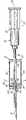
图1是本发明的针头保护器的第一实施例在针加载状态的透视图。Figure 1 is a perspective view of a first embodiment of the needle protector of the present invention in a needle loaded state.
图2是与图1相似的图,示出图1中的针头保护器的针卸载状态以及限定对针头的阻挡件。Fig. 2 is a view similar to Fig. 1 showing the needle unloaded state of the needle protector of Fig. 1 and defining a stop for the needle.
图3是图1中的针头保护器的轴向截面图;Fig. 3 is an axial sectional view of the needle protector in Fig. 1;
图4是图2中的针头保护器的轴向截面图;Fig. 4 is an axial sectional view of the needle protector in Fig. 2;
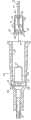
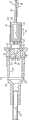
图5是本发明的针头保护器的第二实施例在针加载状态的轴向截面图;Figure 5 is an axial sectional view of a second embodiment of the needle protector of the present invention in a needle loading state;
图6是与图5相似的图,示出图5中的针头保护器处于针卸载状态并限定对针头的阻挡件;Figure 6 is a view similar to Figure 5, showing the needle protector of Figure 5 in a needle unloaded state and defining a stop for the needle;
图7是图6中的针头保护器的局部截面侧视图,该针头保护器依照本发明的原理与管套相联并附接于管套座;Fig. 7 is a partial cross-sectional side view of the needle protector of Fig. 6 associated with the hub and attached to the hub seat in accordance with the principles of the present invention;
图8是与图7类似的图,示出针头保护器从管套座中释放出来;Figure 8 is a view similar to Figure 7 showing the release of the needle protector from the socket;
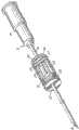
图9是图1中的针头保护器的透视图,具体是剖开图,该针头保护器带有外壳;Fig. 9 is a perspective view of the needle protector in Fig. 1, specifically a cutaway view, the needle protector has a shell;
图10是图9中的针头保护器和外壳在针加载位置的局部截面侧视图,其中示出的管套座接合指状件固定于管套座;Figure 10 is a partial cross-sectional side view of the needle protector and housing of Figure 9 in the needle loaded position, with the hub engagement fingers shown secured to the hub;
图11是与图10类似的图,示出在针卸载位置从管套座释放出来的所述座接合指状件。Figure 11 is a view similar to Figure 10 showing the hub engaging fingers released from the hub hub in the needle unloaded position.
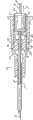
图12是依照本发明原理的、处在针加载状态中的针头保护器第三实施例的轴线截面图;和12 is an axial cross-sectional view of a third embodiment of a needle protector in a needle-loaded state in accordance with the principles of the present invention; and
图13是与图12类似的针卸载状态中的图。FIG. 13 is a diagram similar to FIG. 12 in a needle unloaded state.
具体实施方式Detailed ways
关于图1-4,示出了针头保护器的第一实施例10,所述针头保护器用于与具有从针座15延伸的针柄14和针头16的针12配合使用。针头保护器10包括例如是壁或圆盘(或多个,重叠部件,未示出)的支撑部件20,其具有或限定孔22以可伸缩地容纳针12的针柄14。可以是金属丝(细条或宽带)的一对弹簧臂24,26,在朝着尖头16的方向上从支承部件20延伸。一对有孔部件28,30分别与弹簧臂24和26连接。有孔部件可以是壁或其它类似结构,有利方式为如图1所示的圆盘。部件28和30分别有例如为圆的或其它形状的孔32,34,其大小可以容纳从中穿过的针12的针柄14。Referring to Figures 1-4, a
部件28,30可以被推成对齐方式,例如通过依靠外力径向地相向推进,使得孔32和34与公共轴线例如针12的纵轴线36对齐。对齐后,针柄14被可伸缩地容纳穿过支承部件的孔22和有孔部件28,30的孔32,34,以便如图1所示限定针12的加载位置。弹簧臂24,26用于促使圆盘28和30分开,使得孔32,34与公共轴线36脱离对齐。为此,当针14从图1和3的加载位置缩回(如图3中箭头37所指)到卸载位置时,例如图2和4中所示,针柄14从孔32移出,根据设计和有孔部件28和30之间的间距也可能从孔34中出来,以允许部件28和/或30径向向外移动(如图2和3中箭头38所示),与针12的轴线36脱离对齐。在卸载位置,有孔部件28,30不对齐以便提供阻挡件,以阻止针头16回到针12的加载位置。
为了限制有孔部件28和30的不对齐,例如,使它们不会分开太远并在它们之间形成适合于针头16再出现的间隙,部件28和30可以有利地在横过针柄14的轴线36或与轴线36垂直的方向上延伸,使得它们限定面对的面40,42,这两个面分别设置有位置相对的壁架44,46(图3和4)。如图3所示,在针12的加载位置,壁架44和46可以间隔开至针柄14的每侧。但是,随着针12移动到卸载位置,如图4举例所示,部件28和/或30可以由于弹簧臂24,26的作用自由径向移动而不对齐。但是,向外径向移动的程度受限于通过互相抵靠相互配合的壁架44,46。In order to limit the misalignment of the
虽然所示的针头保护器10的有孔部件28,30是向内移动对齐,向外移动不对齐的,但也可以使用反方向的移动。为此,参照图5和6,可以看到针头保护器的替换实施例10’具有有孔部件28’和30’,孔32’和34’偏置,使其到边缘48,49的距离比到50,51的距离近,弹簧臂24,26附接于后者或其附近。部件28’和30’可以是扁圆形或圆形这样的圆盘形状,并且彼此径向向外移,使得孔32’,34’对齐以便处在加载位置的针如图5所示地穿过该处压缩。弹簧臂24,26同时推进部件28’,30’(如图5中箭头38’所指),使得针12从加载位置移动到卸载位置,如图6中举例所示,有孔部件28’和30’径向地相向移动以便不与针轴线36对齐,并因此提供需要的阻挡以防止针头16重新出现。在实施例10’中,由于有弹簧臂24抵靠部件30’,所以不需要壁架,但是也可以提供壁架。While the
针头保护器10’的另一方面有利于其与管套52一起使用。具体地,参照图7可以看到,在针12的加载位置,部件28’,30’的一个或多个边缘50,51被推靠在管座56的内壁54上并在该处夹紧。边缘50,51可以附加或替换地容纳于管座的内壁54的凹槽58(可以是环形的)中。边缘50,51可以是部件28’,30’的外围部分,或者可以是附接于该处或形成于其上的伸出元件。因此,在针12的加载位置,例如针12延伸穿过管套57使得针头16从该处伸出时,针头保护器10’位于管套座56内部并固定其中。尽管未示出,应该知道,针座15可以构成闪回室(flashback chamber)的一部分、或者附接到其上或连通到其中。针12移动(在图8中箭头37的方向)到卸载状态时,如图8所示,部件28’,30’不仅径向内移使其提供防止针头16重新出现的阻挡件,还离开管套座的壁54,从而允许针头保护器10’顺利离开管套座56。Another aspect of needle protector 10' facilitates its use with
可以给针12的针柄14提供不规则体(在图8中以虚线示出),例如卷曲的,隆起的,或其它伸出结构,以在靠近针头16处形成针柄14的一过大部分。支撑部件20的孔的尺寸可被设计成避免不规则体62压迫穿过所述孔,使得在如图8所示的针12的卸载位置,针头16被保持在部件28’,30’(或使用保护器10的部件28,30)与支撑部件20之间。如果使用不规则体62,它必须足够小以便通过孔32’和34’,但是不能小到可以通过支撑部件20中的孔22的程度。此外,孔32’和34’(或32和34)可能需要将其开口形状设计成在针从加载状态缩回时帮助不规则体进入孔。The
可替换地或另外地,如图9所示,可以提供外壳64,其近端壁66限定支撑部件20。可替换地,弹簧臂22,24可以从外壳64的远端壁68延伸,使得壁68限定支承部件20。外壳64可以是圆柱或其它形状的塑料或金属结构,其经设计可伸缩地被接收在针柄14上,针头16从外壳64中伸出。因此,外壳64给保护器10内的针头16和保护器10提供罩,以减少有孔部件28,30会被一起推回并允许针头16重新出现的可能性。根据尺寸,外壳64也可以放置在管套座56中,针头保护器10和10’可以是金属的和/或塑料的。例如,部件28,30或28’,30’和弹簧臂24,26可以是金属的,支撑部件20可以是金属的,或者可以是塑料的,特别是在外壳64为塑料形式的情况下。Alternatively or additionally, as shown in FIG. 9 , a
外壳64可以修改成如图10所示的外壳64’,其包含弹性指状件70,72,这两个指状件从外壳64的远端壁68延伸出,通常径向向内偏置,以便被一起推进。限定在指状件70,72之间的区域74通常比针柄14的直径小,如图10所示,使得随着针柄14从中伸缩,指状件70,72被径向向外抵靠管套座的内壁54,以便将外壳64保持到管套座56上。有利的是,指状件70,72都包含锁止件76,锁止件76适合与管套座56的凹槽58配合以便加强固定。如图11中虚线所示,针12移动(在图10中箭头37的方向上)到卸载位置时,针柄14不再使指状件70和72完全分开,因此它们彼此相向运动(如图11中箭头77所指),释放管套座56上的固定,以便因此在进一步将针1沿如图11中箭头78所指方向拉离管套座56时可顺利从管套座56释放出来。指状件70,72的结构和操作可以如美国专利No.5,599,310所示的那样,该专利的公开全部以参考方式并入此处。外壳64’的尺寸被设计成使其包含针头保护器10和10’(图10和11出于参考的目的只用虚线示出了保护器10’),并将其中的任何一个安装在管套座56内或外部,有孔部件28,30或28’,30’的尺寸也被设计成使它们可被安装在管套座56内。
针头16可以由于不规则体62(见图8)而固定在外壳64或64’内。另外或替换地,外壳64或64’中可以包含结构以便有效夹紧针12的针柄14,尤其是在针12已处于卸载状态的情况下。一些示例是延伸凸缘或伸出部分,该部分夹紧在如欧洲专利No.0352928B2中所示的针的狭槽中,如美国专利No.5,328,482所示的锁定夹中,或如前述美国专利No.5,328,482或美国专利No.5,458,658;No.611,781;或No.5,662,610中所示的其它结构中。替换地,依照本发明的另外方面,如将参照图12和13描述的那样,针头保护器的第三实施例80是由U形夹81形式的活动针夹紧结构提供的。特别的是,U形夹81包含一对支腿或壁82,84,轭状物86在它们之间延伸。另外,在每个支腿82,84中分别形成孔87,88,它们被设计成在夹子81的第一或加载位置让针柄14自由从中穿过,其中,如图12所示,例如支腿82,84通常竖直导向或互相平行,并且如图13所示,孔可在夹子81处于第二或卸载状态时夹紧针柄14的表面,其中,例如支腿82,84相对于它们在图12中的位置有一定角度的偏移(有利地沿图13中箭头89和89’的方向上向外)。
夹子81有利地是一片有弹性的弹簧金属成形塑料使其通常趋向于处于第二状态(图13),但是可以弯曲或收缩进图12所示的第一状态。夹子81的双支腿特征提供针柄14上的有利的双向夹,使得夹子81可以足以限定针头保护器。为此,夹子81可以包含在外壳64内,如果需要,该外壳也可以是支撑有孔部件28,30或28’或30’的外壳(图12和13未示出)。外壳64的近端壁和远端壁66,68都允许针柄14从中穿过,但是夹子80则不允许。
可以给夹子81提供触发机构90。特别地,触发机构90可以是底壁92,其带有前保持件94,前保持件94中形成有孔或槽96,孔或槽的尺寸适于在图12的针加载位置使针柄14从中穿过。随着针柄14延伸穿过孔96,底壁92被固定在与针柄14的间距固定的位置,使得夹子支腿82,84可以固定在底壁92的直立夹子壁架100,102之间的第一状态。壁架100,102可以由底壁92的切口或凹处的端面限定。针12在箭头37的方向上移动到卸载位置时,如图13中举例所示,机构90从针柄14倾斜或跌落(如图13中箭头106所指),由此释放支腿82,84,使它们可以处于第二位置以夹紧针柄14。为了便于倾斜动作,触发机构90可以是弹性金属或塑料条,可枢轴铰接到外壳64的近端壁66并由此向下偏置,并且/或者可以包含一个或多个弹簧(未示出)以提供偏置。A
在卸载状态,如图13所示,针头16固定在外壳64内部。可以给外壳64提供一个或多个安置在支腿82,84的外部的凸轮110,112。响应于推动或拉动针12,每个凸轮110,112协作将夹子81的各个支腿82,84推入进一步的角度偏置。尤其是,如果将针12拉到图13的右侧,夹子支腿84会挤压凸轮112的表面,使支腿84沿箭头89’的方向进一步向外枢转,以由此进一步通过支腿84增强支腿84在针柄14上的夹紧力。同样,如果针12被推到图13的左侧,夹子支腿82会挤压凸轮112的表面116,使支腿82沿箭头89的方向上进一步向外枢转,以由此进一步加强支腿82在针柄14上的夹紧力。为了提高支腿82,84的枢转能力,例如,表面114和116可以以与针柄14垂直的平面118成一定的角度延伸,其中该角度与第二状态中相关夹子支腿82或84的通常角偏移相匹配。In the unloaded state, as shown in FIG. 13 , the
虽然夹子81在有利地容纳触发机构90的相对固定的外壳64中示出,但是应该知道,可以由例如保护器10提供夹子81的全部或部分容纳物和/或触发机构。While
虽然已通过对本发明实施例的说明对其进行图解,虽然已相当详细地描述了这些实施例,但那并不是为了约束或以任何方式限制这些细节的权利要求附件的范畴。本领域的技术人员会很容易了解本发明的其它优点和变体。举例来说,在与管套52一起使用的情况下,针头保护器10或10’可以通过与管套座56的内壁直接相互作用来固定于管套座56。替换地,针头保护器10或10’可以通过与管套座56的外壁(直接或间接)相互作用来固定于管套座56。此外,根据支撑部件20限定的总厚度和孔尺寸,支撑部件20及其相关孔22可以用于使针头保护器10或10’和/或外壳64对齐。另外,特氟龙(Teflon)补片擦拭器(未示出)可以放置在外壳64内部以帮助容纳会流入针柄14的血液。因此,本发明在其更广的方面不限于这些特殊细节,典型设备与方法和示出及描述的说明性示例。因此,在没有违背本发明总体发明思想的情况下可以偏离这些细节。While embodiments of the invention have been illustrated by way of illustration, and although these embodiments have been described in some detail, that is not intended to restrict or limit in any way the scope of the claims appended to such details. Other advantages and variations of the invention will readily appear to those skilled in the art. For example, in the case of use with
Claims (44)
Applications Claiming Priority (2)
| Application Number | Priority Date | Filing Date | Title |
|---|---|---|---|
| US54484304P | 2004-02-13 | 2004-02-13 | |
| US60/544,843 | 2004-02-13 |
Publications (2)
| Publication Number | Publication Date |
|---|---|
| CN1917913A CN1917913A (en) | 2007-02-21 |
| CN100558420Ctrue CN100558420C (en) | 2009-11-11 |
Family
ID=34886088
Family Applications (1)
| Application Number | Title | Priority Date | Filing Date |
|---|---|---|---|
| CNB2005800047295AExpired - Fee RelatedCN100558420C (en) | 2004-02-13 | 2005-02-03 | needle protector |
Country Status (15)
| Country | Link |
|---|---|
| US (3) | US7347838B2 (en) |
| EP (2) | EP1762262A3 (en) |
| JP (1) | JP2007521918A (en) |
| KR (1) | KR20060130653A (en) |
| CN (1) | CN100558420C (en) |
| AR (1) | AR051347A1 (en) |
| AU (3) | AU2005215370B2 (en) |
| BR (1) | BRPI0507488A (en) |
| CA (2) | CA2555068A1 (en) |
| MX (1) | MXPA06009272A (en) |
| PA (1) | PA8623601A1 (en) |
| PE (1) | PE20050969A1 (en) |
| TW (1) | TWI294291B (en) |
| WO (1) | WO2005079891A1 (en) |
| ZA (1) | ZA200606528B (en) |
Families Citing this family (136)
| Publication number | Priority date | Publication date | Assignee | Title |
|---|---|---|---|---|
| US6749588B1 (en) | 1998-04-09 | 2004-06-15 | Becton Dickinson And Company | Catheter and introducer needle assembly with needle shield |
| US8177762B2 (en) | 1998-12-07 | 2012-05-15 | C. R. Bard, Inc. | Septum including at least one identifiable feature, access ports including same, and related methods |
| DE20210394U1 (en) | 2002-07-04 | 2002-09-12 | B. Braun Melsungen Ag, 34212 Melsungen | catheter introducer |
| US11083841B2 (en) | 2002-08-09 | 2021-08-10 | Fenwal, Inc. | Needle protector, needle assembly and fluid processing set including the same |
| US7988664B2 (en)* | 2004-11-01 | 2011-08-02 | Tyco Healthcare Group Lp | Locking clip with trigger bushing |
| EP1715906A4 (en)* | 2004-02-18 | 2008-12-17 | Univ Mcgill | DEVICE FOR INJECTING VISCOUS SUBSTANCE INTO HARD TISSUE |
| US7947022B2 (en) | 2005-03-04 | 2011-05-24 | C. R. Bard, Inc. | Access port identification systems and methods |
| JP5484674B2 (en) | 2005-03-04 | 2014-05-07 | シー・アール・バード・インコーポレーテッド | Access port and identification method |
| US9474888B2 (en) | 2005-03-04 | 2016-10-25 | C. R. Bard, Inc. | Implantable access port including a sandwiched radiopaque insert |
| US8029482B2 (en) | 2005-03-04 | 2011-10-04 | C. R. Bard, Inc. | Systems and methods for radiographically identifying an access port |
| EP1874393B1 (en) | 2005-04-27 | 2017-09-06 | C.R.Bard, Inc. | Infusion apparatuses |
| US10307581B2 (en) | 2005-04-27 | 2019-06-04 | C. R. Bard, Inc. | Reinforced septum for an implantable medical device |
| EP3884989B1 (en) | 2005-04-27 | 2022-07-13 | C. R. Bard, Inc. | Vascular access port |
| EP1907042B1 (en) | 2005-07-06 | 2009-03-11 | Vascular Pathways Inc. | Intravenous catheter insertion device and method of use |
| US7753877B2 (en) | 2005-08-08 | 2010-07-13 | Smiths Medical Asd, Inc. | Needle guard strut wall clip |
| US7632243B2 (en)* | 2005-08-08 | 2009-12-15 | Smiths Medical Asd, Inc. | Duckbill catheter release mechanism |
| US7597681B2 (en)* | 2005-08-08 | 2009-10-06 | Smiths Medical Asd, Inc. | Needle guard mechanism with shroud |
| US8251950B2 (en)* | 2005-08-08 | 2012-08-28 | Smiths Medical Asd, Inc. | Needle guard clip with heel |
| US8162881B2 (en) | 2005-08-08 | 2012-04-24 | Smiths Medical Asd, Inc. | Needle guard mechanism with angled strut wall |
| US8403886B2 (en) | 2005-08-08 | 2013-03-26 | Smiths Medical Asd, Inc. | Needle guard clip with lip |
| JP4921779B2 (en) | 2005-11-28 | 2012-04-25 | 日本コヴィディエン株式会社 | Indwelling needle |
| US9186455B2 (en)* | 2006-02-14 | 2015-11-17 | B. Braun Medical Inc. | Port access device |
| US20080086089A1 (en)* | 2006-07-10 | 2008-04-10 | Isaacson S Ray | Magnetically induced safety technology |
| US8308691B2 (en) | 2006-11-03 | 2012-11-13 | B. Braun Melsungen Ag | Catheter assembly and components thereof |
| US8382718B2 (en) | 2006-07-31 | 2013-02-26 | B. Braun Melsungen Ag | Needle assembly and components thereof |
| US8257313B2 (en)* | 2006-08-11 | 2012-09-04 | Becton, Dickinson And Company | Integrated septum and needle tip shield for a catheter assembly |
| JP4994775B2 (en) | 2006-10-12 | 2012-08-08 | 日本コヴィディエン株式会社 | Needle point protector |
| AU2012244299B2 (en)* | 2006-11-03 | 2013-12-05 | B. Braun Melsungen Ag | Catheter assembly and components thereof |
| US9265912B2 (en) | 2006-11-08 | 2016-02-23 | C. R. Bard, Inc. | Indicia informative of characteristics of insertable medical devices |
| US9642986B2 (en) | 2006-11-08 | 2017-05-09 | C. R. Bard, Inc. | Resource information key for an insertable medical device |
| US9056188B2 (en) | 2006-11-22 | 2015-06-16 | Becton, Dickinson And Company | Needle shielding flag structures |
| US8425469B2 (en) | 2007-04-23 | 2013-04-23 | Jacobson Technologies, Llc | Systems and methods for controlled substance delivery network |
| EP2150304B1 (en) | 2007-05-07 | 2010-12-01 | Vascular Pathways Inc. | Intravenous catheter insertion and blood sample devices and method of use |
| ES2651269T3 (en) | 2007-06-20 | 2018-01-25 | Medical Components, Inc. | Venous reservoir with molded indications and / or radiopacas |
| DE202007009977U1 (en)* | 2007-07-17 | 2007-11-08 | Poly Medicure Ltd. | Needle securing device for an intravenous catheter device |
| EP2279770B1 (en) | 2007-07-17 | 2012-07-11 | Poly Medicure Ltd. | Needle |
| US9610432B2 (en) | 2007-07-19 | 2017-04-04 | Innovative Medical Devices, Llc | Venous access port assembly with X-ray discernable indicia |
| WO2009012385A1 (en)* | 2007-07-19 | 2009-01-22 | Medical Components, Inc. | Venous access port assembly with x-ray discernable indicia |
| US7713243B2 (en)* | 2007-09-25 | 2010-05-11 | Becton, Dickinson And Company | Tip shield for needle stick prevention |
| US9579496B2 (en) | 2007-11-07 | 2017-02-28 | C. R. Bard, Inc. | Radiopaque and septum-based indicators for a multi-lumen implantable port |
| WO2009067646A1 (en)* | 2007-11-21 | 2009-05-28 | Becton, Dickinson And Company | Needle safety device |
| MX2010005610A (en) | 2007-11-21 | 2010-06-01 | Becton Dickinson Co | Safety needle guard. |
| ES2432243T3 (en)* | 2008-03-17 | 2013-12-02 | Poly Medicure Limited | Needle safety device |
| US7828774B2 (en)* | 2008-05-12 | 2010-11-09 | Harding Weston F | Sleeved clip safety |
| EP2296735A4 (en)* | 2008-05-14 | 2013-05-29 | John Stephens | Needle protective device |
| EP2251057B1 (en)* | 2008-05-28 | 2012-07-11 | Poly Medicure Ltd. | Catheter introducer |
| US8398597B2 (en)* | 2008-06-17 | 2013-03-19 | Becton, Dickinson And Company | Needle shield and interlock |
| US7785296B2 (en)* | 2008-07-17 | 2010-08-31 | Smiths Medical Asd, Inc. | Needle tip spring protector |
| BRPI0920464B8 (en)* | 2008-10-03 | 2021-06-22 | Nipro Corp | needle tip protector and permanent needle mount |
| ES2906416T3 (en) | 2008-10-31 | 2022-04-18 | Bard Inc C R | Systems and methods to identify an access road |
| US11890443B2 (en) | 2008-11-13 | 2024-02-06 | C. R. Bard, Inc. | Implantable medical devices including septum-based indicators |
| US8932271B2 (en) | 2008-11-13 | 2015-01-13 | C. R. Bard, Inc. | Implantable medical devices including septum-based indicators |
| DE102009020061A1 (en) | 2009-05-06 | 2010-11-11 | B. Braun Melsungen Ag | Needle protection device for a medical hollow needle |
| WO2010144533A1 (en) | 2009-06-09 | 2010-12-16 | Jacobson Technologies, Llc | Controlled delivery of substances system and method |
| EP2451512A1 (en) | 2009-07-07 | 2012-05-16 | C.R. Bard Inc. | Extensible internal bolster for a medical device |
| SE534021C2 (en) | 2009-08-13 | 2011-04-05 | Vigmed Ab | Protective device for a catheter needle tip |
| ES2695907T3 (en) | 2009-11-17 | 2019-01-11 | Bard Inc C R | Overmolded access port that includes anchoring and identification features |
| DK2536455T3 (en)* | 2010-02-18 | 2014-06-23 | Sanofi Aventis Deutschland | FINGER PROTECTION FOR AN INJECTION DEVICE |
| SE535169C2 (en) | 2010-04-13 | 2012-05-08 | Vigmed Ab | Polymer protective device for a catheter needle tip |
| US9950139B2 (en) | 2010-05-14 | 2018-04-24 | C. R. Bard, Inc. | Catheter placement device including guidewire and catheter control elements |
| US10384039B2 (en) | 2010-05-14 | 2019-08-20 | C. R. Bard, Inc. | Catheter insertion device including top-mounted advancement components |
| US8932258B2 (en) | 2010-05-14 | 2015-01-13 | C. R. Bard, Inc. | Catheter placement device and method |
| US11925779B2 (en) | 2010-05-14 | 2024-03-12 | C. R. Bard, Inc. | Catheter insertion device including top-mounted advancement components |
| US9872971B2 (en) | 2010-05-14 | 2018-01-23 | C. R. Bard, Inc. | Guidewire extension system for a catheter placement device |
| US8257322B2 (en) | 2010-06-02 | 2012-09-04 | Smiths Medical Asd, Inc. | Tip protector for a safety catheter |
| US9011388B2 (en)* | 2010-06-04 | 2015-04-21 | Smiths Medical Asd, Inc. | Passive safety portal device |
| RU2729036C2 (en)* | 2010-08-05 | 2020-08-03 | Б. Браун Мельзунген Аг | Safe needle device and assembly |
| EP2613824A1 (en)* | 2010-09-10 | 2013-07-17 | C.R. Bard Inc. | Systems for isolation of a needle-based infusion set |
| US10525234B2 (en) | 2010-09-10 | 2020-01-07 | C. R. Bard, Inc. | Antimicrobial/haemostatic interface pad for placement between percutaneously placed medical device and patient skin |
| US20140066894A1 (en) | 2010-09-10 | 2014-03-06 | C. R. Bard, Inc. | Self-Sealing Pad for a Needle-Based Infusion Set |
| US20130178807A1 (en)* | 2010-09-21 | 2013-07-11 | Poly Medicure Limited | Needle tip guard for intravenous catheter assembly |
| ES2721902T5 (en) | 2010-09-23 | 2023-06-28 | Greiner Bio One Gmbh | Needle tip protection device |
| EP2438952A1 (en)* | 2010-10-08 | 2012-04-11 | Sanofi-Aventis Deutschland GmbH | Finger guard for an injection device |
| USD676955S1 (en) | 2010-12-30 | 2013-02-26 | C. R. Bard, Inc. | Implantable access port |
| USD682416S1 (en) | 2010-12-30 | 2013-05-14 | C. R. Bard, Inc. | Implantable access port |
| US8690833B2 (en) | 2011-01-31 | 2014-04-08 | Vascular Pathways, Inc. | Intravenous catheter and insertion device with reduced blood spatter |
| ES2835652T3 (en) | 2011-02-25 | 2021-06-22 | Bard Inc C R | Medical component insertion device including a retractable needle |
| US9238104B2 (en) | 2011-02-28 | 2016-01-19 | Injectimed, Inc. | Needle guard |
| US8764711B2 (en)* | 2011-02-28 | 2014-07-01 | Injectimed, Inc. | Needle guard |
| ES2662356T3 (en) | 2011-04-27 | 2018-04-06 | Kpr U.S., Llc | Safety IV catheter assemblies |
| USD903101S1 (en) | 2011-05-13 | 2020-11-24 | C. R. Bard, Inc. | Catheter |
| US8591467B2 (en) | 2011-07-25 | 2013-11-26 | Covidien Lp | Vascular access assembly and safety device |
| CN102363056B (en) | 2011-08-01 | 2013-06-05 | 上海萌黎国际贸易有限公司 | Needle head protection device and safety needle component |
| EP2572745A1 (en)* | 2011-09-23 | 2013-03-27 | Sanofi-Aventis Deutschland GmbH | Needle safety device |
| EP2760521B1 (en) | 2011-09-26 | 2016-01-06 | Covidien LP | Safety iv catheter and needle assembly |
| WO2013048975A1 (en) | 2011-09-26 | 2013-04-04 | Covidien Lp | Safety catheter |
| US8834422B2 (en) | 2011-10-14 | 2014-09-16 | Covidien Lp | Vascular access assembly and safety device |
| EP2586479A1 (en)* | 2011-10-31 | 2013-05-01 | Sanofi-Aventis Deutschland GmbH | Safety needle assembly |
| CA2854003C (en) | 2011-11-07 | 2020-07-14 | Safety Syringes, Inc. | Contact trigger release needle guard |
| KR101785356B1 (en)* | 2011-11-08 | 2017-10-16 | 폴리 메디큐어 리미티드 | Intravenous catheter apparatus |
| MX2011013382A (en)* | 2011-12-12 | 2013-06-20 | Equipos Medicos Vizcarra S A | Safety peripheral intravenous catheter having a quick, painless puncture system. |
| IN2012DE00486A (en)* | 2012-02-21 | 2015-06-05 | Poly Medicure Ltd | |
| JP2015521892A (en)* | 2012-07-04 | 2015-08-03 | ヴィグメッド アーベー | Needle shield and needle assembly for a needle assembly |
| WO2014120741A1 (en) | 2013-01-30 | 2014-08-07 | Vascular Pathways, Inc. | Systems and methods for venipuncture and catheter placement |
| US10357635B2 (en) | 2013-03-12 | 2019-07-23 | Teleflex Medical Incorporated | Catheter insertion device |
| US11224724B2 (en) | 2013-03-12 | 2022-01-18 | Teleflex Medical Incorporated | Catheter insertion device |
| US9717886B2 (en) | 2013-03-12 | 2017-08-01 | Teleflex Medical Incorporated | Safety clip for a needle |
| US9555221B2 (en) | 2014-04-10 | 2017-01-31 | Smiths Medical Asd, Inc. | Constant force hold tip protector for a safety catheter |
| KR101491953B1 (en)* | 2014-07-21 | 2015-02-11 | 송재원 | Medicine injection niddle unit having stick injury and infection preventing fuction |
| WO2016037127A1 (en) | 2014-09-05 | 2016-03-10 | C.R. Bard, Inc. | Catheter insertion device including retractable needle |
| USD903100S1 (en) | 2015-05-01 | 2020-11-24 | C. R. Bard, Inc. | Catheter placement device |
| CN113350614A (en) | 2015-05-15 | 2021-09-07 | C·R·巴德股份有限公司 | Catheter placement device including extendable needle safety feature |
| WO2017201369A1 (en) | 2016-05-20 | 2017-11-23 | Smiths Medical Asd, Inc. | Needle assembly with flexible catheter nose for diagnostic sampling of fluid |
| CA3030891A1 (en) | 2016-07-27 | 2018-02-01 | Becton, Dickinson And Company | Infusion bump capture needle shield |
| US10493262B2 (en) | 2016-09-12 | 2019-12-03 | C. R. Bard, Inc. | Blood control for a catheter insertion device |
| EP3528723B1 (en) | 2016-10-27 | 2023-08-16 | C. R. Bard, Inc. | Intraosseous access device |
| US10814073B2 (en)* | 2016-12-13 | 2020-10-27 | Becton, Dickinson And Company | Safety device with collapsible housing and trigger activation |
| EP3585471B1 (en) | 2017-03-01 | 2025-01-01 | C. R. Bard, Inc. | Catheter insertion device |
| US10946176B2 (en) | 2017-04-06 | 2021-03-16 | Becton, Dickinson And Company | Intravenous catheter assembly with safety clip |
| EP4480525A3 (en) | 2017-04-13 | 2025-04-09 | Teleflex Medical Incorporated | Catheter insertion device |
| KR101860712B1 (en)* | 2017-12-08 | 2018-05-24 | 이규원 | Syringe to prevent piercing |
| ES2980192T3 (en) | 2018-03-07 | 2024-09-30 | Bard Access Systems Inc | Guidewire advancement and blood reflux systems for a medical device insertion system |
| WO2019199734A1 (en) | 2018-04-11 | 2019-10-17 | Smiths Medical Asd, Inc. | Spring retract iv catheter |
| EP3773856B1 (en)* | 2018-04-11 | 2025-07-09 | ICU Medical, Inc. | Iv catheter with a tip protector |
| US11857320B2 (en) | 2018-06-08 | 2024-01-02 | Smiths Medical Asd, Inc. | Blood sequestration device and method |
| USD921884S1 (en) | 2018-07-27 | 2021-06-08 | Bard Access Systems, Inc. | Catheter insertion device |
| CA3151126A1 (en) | 2019-08-19 | 2021-02-25 | Becton, Dickinson And Company | Midline catheter placement device |
| CA3169051A1 (en) | 2019-09-10 | 2021-03-18 | Medsource International Llc | An intravenous catheter device |
| CN212879457U (en) | 2019-09-27 | 2021-04-06 | 巴德阿克塞斯系统股份有限公司 | Self-advancing intraosseous access device and intraosseous access device |
| US11759235B2 (en) | 2019-09-27 | 2023-09-19 | Bard Access Systems, Inc. | Constant-torque intraosseous access devices and methods thereof |
| WO2021062215A1 (en) | 2019-09-27 | 2021-04-01 | Bard Access Systems, Inc. | Step needle for intraosseous access device |
| CN212879505U (en) | 2019-09-27 | 2021-04-06 | 巴德阿克塞斯系统股份有限公司 | Intraosseous access device |
| US12279793B2 (en)* | 2019-10-16 | 2025-04-22 | Fresenius Kabi Deutschland Gmbh | Cannula device |
| CN111012978B (en)* | 2020-01-21 | 2024-12-27 | 贝普医疗科技股份有限公司 | Indwelling needle with eccentric baffle for shielding needle |
| CN113317840A (en) | 2020-02-28 | 2021-08-31 | 巴德阿克塞斯系统股份有限公司 | Flexible intra-osseous obturator |
| WO2021216521A1 (en) | 2020-04-21 | 2021-10-28 | Bard Access Systems , Inc. | Reusable push-activated intraosseous access device |
| CN113749724A (en) | 2020-06-03 | 2021-12-07 | 巴德阿克塞斯系统股份有限公司 | Intraosseous device including sensing obturator |
| US12318557B2 (en) | 2020-06-16 | 2025-06-03 | Becton, Dickinson And Company | Catheter system to provide needle safety and related methods |
| CN216167681U (en) | 2020-07-17 | 2022-04-05 | 巴德阿克塞斯系统股份有限公司 | Safety mechanism |
| CN216628654U (en) | 2020-08-25 | 2022-05-31 | 巴德阿克塞斯系统股份有限公司 | Angled intraosseous access system |
| CN215839325U (en) | 2020-09-09 | 2022-02-18 | 巴德阿克塞斯系统股份有限公司 | Suction device for an intraosseous access system |
| CN217960227U (en) | 2021-02-08 | 2022-12-06 | 巴德阿克塞斯系统股份有限公司 | Intraosseous access system |
| US12337123B2 (en) | 2021-05-06 | 2025-06-24 | Medsource Labs, Llc | Safety intravenous cannula |
| US12186497B2 (en) | 2022-01-14 | 2025-01-07 | Medsource International Llc | Intravenous cannula |
| WO2023141039A1 (en)* | 2022-01-24 | 2023-07-27 | Becton, Dickinson And Company | Catheter system having a blood shield |
| WO2024211166A1 (en)* | 2023-04-06 | 2024-10-10 | Becton, Dickinson And Company | Passive safety catheter system |
Citations (5)
| Publication number | Priority date | Publication date | Assignee | Title |
|---|---|---|---|---|
| US5458658A (en)* | 1989-02-01 | 1995-10-17 | Sero-Guard Corporation | Positive locking needle-mounted needle guard for needle supported catheters |
| US5599310A (en)* | 1995-06-07 | 1997-02-04 | Johnson & Johnson Medical, Inc. | I.V. catheter assembly with automatic cannula tip guard |
| US5718688A (en)* | 1994-08-24 | 1998-02-17 | Sterimatic Holdings Limited | Catheter placement units |
| DE20104539U1 (en)* | 2000-08-14 | 2001-12-20 | B. Braun Melsungen Ag, 34212 Melsungen | Intravenous catheter device |
| CN1427731A (en)* | 2000-11-21 | 2003-07-02 | 贝克顿迪肯森公司 | Catheter and introducer needle assembly with needle shield |
Family Cites Families (33)
| Publication number | Priority date | Publication date | Assignee | Title |
|---|---|---|---|---|
| US611781A (en) | 1898-10-04 | Island | ||
| US5013305A (en) | 1988-06-29 | 1991-05-07 | Opie Eric A | Needle safety system and method |
| US4952207A (en) | 1988-07-11 | 1990-08-28 | Critikon, Inc. | I.V. catheter with self-locating needle guard |
| US4929241A (en) | 1988-08-05 | 1990-05-29 | Kulli John C | Medical needle puncture guard |
| US4964854A (en) | 1989-01-23 | 1990-10-23 | Luther Medical Products, Inc. | Intravascular catheter assembly incorporating needle tip shielding cap |
| ES2081973T3 (en) | 1989-02-01 | 1996-03-16 | Sero Guard Corp | AUTOMATIC DISPOSABLE HYPODERMIC NEEDLE PROTECTOR. |
| US5662610A (en) | 1989-02-01 | 1997-09-02 | Sircom; Richard C. | Automatic needle guard tip protection |
| US5279591A (en) | 1990-07-16 | 1994-01-18 | Simon Alexander Z | Protector for needle catheter |
| JP3105096B2 (en) | 1992-10-31 | 2000-10-30 | 日本ケミカルリサーチ株式会社 | Syringe with needle tube storage mechanism |
| US5584809A (en) | 1993-07-20 | 1996-12-17 | Graphic Controls Corporation | Safety catheter |
| US5419766A (en) | 1993-09-28 | 1995-05-30 | Critikon, Inc. | Catheter with stick protection |
| US5419776A (en)* | 1993-09-30 | 1995-05-30 | Baer; Robert M. | Pneumothorax treatment device |
| US6203527B1 (en) | 1994-03-29 | 2001-03-20 | Filiberto P. Zadini | Bi-directional clamping guard for needle stick protection |
| US5683365A (en) | 1995-06-07 | 1997-11-04 | Johnson & Johnson Medical, Inc. | Tip protection device |
| US6012213A (en) | 1995-06-07 | 2000-01-11 | Chang; Joseph J. | Method for forming a rib on a cannula for a tip protection device |
| US5882337A (en) | 1995-06-07 | 1999-03-16 | Johnson & Johnson Medical, Inc. | Tip protection device |
| GB9708569D0 (en) | 1997-04-29 | 1997-06-18 | Smiths Industries Ltd | Catheter and needle assemblies |
| US6616630B1 (en) | 1997-08-20 | 2003-09-09 | B. Braun Melsungen A.G. | Spring clip safety IV catheter |
| US6652490B2 (en) | 1998-04-09 | 2003-11-25 | Becton Dickinson And Company | Catheter and introducer needle assembly with compact needle shield |
| US6749588B1 (en) | 1998-04-09 | 2004-06-15 | Becton Dickinson And Company | Catheter and introducer needle assembly with needle shield |
| US6280415B1 (en)* | 1999-03-10 | 2001-08-28 | W. Dudley Johnson | Tissue traction device |
| US6280419B1 (en)* | 1999-08-09 | 2001-08-28 | Arrow International, Inc. | Hypodermic needle guard |
| US6224569B1 (en) | 1999-09-24 | 2001-05-01 | Becton, Dickinson And Company | Compact needle point shield |
| DE29921084U1 (en) | 1999-12-01 | 2000-02-17 | B. Braun Melsungen Ag, 34212 Melsungen | Short catheter |
| US6595954B1 (en) | 2000-03-13 | 2003-07-22 | Luther Research Partners, Llc | Insertion needle and soft catheter system with tip protector |
| US6595955B2 (en)* | 2001-03-15 | 2003-07-22 | Specialized Health Products, Inc. | Safety shield for medical needles |
| US6761706B2 (en) | 2001-04-04 | 2004-07-13 | Patricia B. Vaillancourt | Needle guard |
| DE20106697U1 (en) | 2001-04-18 | 2001-10-31 | B. Braun Melsungen Ag, 34212 Melsungen | Catheter introducer |
| CN2488519Y (en) | 2001-07-13 | 2002-05-01 | 善德生化科技股份有限公司 | One-piece catheter clip with safety needle protection |
| US6652486B2 (en) | 2001-09-27 | 2003-11-25 | Medex, Inc. | Safety catheter |
| US6981965B2 (en) | 2001-10-31 | 2006-01-03 | Luther Research Partners Llc | Universal passive protector for an IV catheter |
| ES2697329T3 (en) | 2002-06-20 | 2019-01-23 | Becton Dickinson Co | Apparatus to protect the tip of a catheter introducer needle |
| US20050075609A1 (en)* | 2003-10-01 | 2005-04-07 | Latona Patrick C. | Protective needle clips |
- 2005
- 2005-02-03EPEP06077107Apatent/EP1762262A3/ennot_activeWithdrawn
- 2005-02-03CACA002555068Apatent/CA2555068A1/ennot_activeAbandoned
- 2005-02-03JPJP2006553160Apatent/JP2007521918A/enactivePending
- 2005-02-03CNCNB2005800047295Apatent/CN100558420C/ennot_activeExpired - Fee Related
- 2005-02-03WOPCT/US2005/003200patent/WO2005079891A1/enactiveApplication Filing
- 2005-02-03CACA002659505Apatent/CA2659505A1/ennot_activeAbandoned
- 2005-02-03MXMXPA06009272Apatent/MXPA06009272A/enunknown
- 2005-02-03KRKR1020067016276Apatent/KR20060130653A/ennot_activeCeased
- 2005-02-03BRBRPI0507488-6Apatent/BRPI0507488A/ennot_activeIP Right Cessation
- 2005-02-03EPEP05712588Apatent/EP1725282A1/ennot_activeWithdrawn
- 2005-02-03AUAU2005215370Apatent/AU2005215370B2/ennot_activeCeased
- 2005-02-05USUS10/906,171patent/US7347838B2/ennot_activeExpired - Fee Related
- 2005-02-11PEPE2005000165Apatent/PE20050969A1/ennot_activeApplication Discontinuation
- 2005-02-11PAPA20058623601Apatent/PA8623601A1/enunknown
- 2005-02-11ARARP050100511Apatent/AR051347A1/enunknown
- 2005-02-14TWTW094104277Apatent/TWI294291B/enactive
- 2006
- 2006-08-04ZAZA200606528Apatent/ZA200606528B/enunknown
- 2006-11-21USUS11/562,204patent/US7534227B2/ennot_activeExpired - Fee Related
- 2007
- 2007-02-13AUAU2007200623Apatent/AU2007200623A1/ennot_activeAbandoned
- 2007-08-06USUS11/834,282patent/US20070270753A1/ennot_activeAbandoned
- 2009
- 2009-02-09AUAU2009200476Apatent/AU2009200476A1/ennot_activeAbandoned
Patent Citations (5)
| Publication number | Priority date | Publication date | Assignee | Title |
|---|---|---|---|---|
| US5458658A (en)* | 1989-02-01 | 1995-10-17 | Sero-Guard Corporation | Positive locking needle-mounted needle guard for needle supported catheters |
| US5718688A (en)* | 1994-08-24 | 1998-02-17 | Sterimatic Holdings Limited | Catheter placement units |
| US5599310A (en)* | 1995-06-07 | 1997-02-04 | Johnson & Johnson Medical, Inc. | I.V. catheter assembly with automatic cannula tip guard |
| DE20104539U1 (en)* | 2000-08-14 | 2001-12-20 | B. Braun Melsungen Ag, 34212 Melsungen | Intravenous catheter device |
| CN1427731A (en)* | 2000-11-21 | 2003-07-02 | 贝克顿迪肯森公司 | Catheter and introducer needle assembly with needle shield |
Also Published As
| Publication number | Publication date |
|---|---|
| EP1762262A2 (en) | 2007-03-14 |
| JP2007521918A (en) | 2007-08-09 |
| WO2005079891A1 (en) | 2005-09-01 |
| TWI294291B (en) | 2008-03-11 |
| AU2005215370A1 (en) | 2005-09-01 |
| AU2007200623A1 (en) | 2007-03-08 |
| US20070149928A1 (en) | 2007-06-28 |
| AU2005215370B2 (en) | 2009-02-05 |
| EP1762262A3 (en) | 2007-03-21 |
| US7534227B2 (en) | 2009-05-19 |
| AR051347A1 (en) | 2007-01-10 |
| US20070270753A1 (en) | 2007-11-22 |
| PA8623601A1 (en) | 2005-08-30 |
| EP1725282A1 (en) | 2006-11-29 |
| ZA200606528B (en) | 2009-10-28 |
| AU2009200476A1 (en) | 2009-02-26 |
| PE20050969A1 (en) | 2005-11-26 |
| KR20060130653A (en) | 2006-12-19 |
| CA2555068A1 (en) | 2005-09-01 |
| BRPI0507488A (en) | 2007-07-10 |
| TW200538177A (en) | 2005-12-01 |
| US7347838B2 (en) | 2008-03-25 |
| CA2659505A1 (en) | 2005-09-01 |
| MXPA06009272A (en) | 2007-02-02 |
| CN1917913A (en) | 2007-02-21 |
| US20050182363A1 (en) | 2005-08-18 |
Similar Documents
| Publication | Publication Date | Title |
|---|---|---|
| CN100558420C (en) | needle protector | |
| AU2002241509B2 (en) | Catheter and introducer needle assembly with needle shield | |
| US6749588B1 (en) | Catheter and introducer needle assembly with needle shield | |
| US20210187251A1 (en) | Intravenous catheter assembly with safety clip | |
| AU2002241509A1 (en) | Catheter and introducer needle assembly with needle shield | |
| JP2001514943A (en) | Spring clip for needle tip protection of safety intravenous catheter | |
| JP2022065054A (en) | Cannula capture mechanism | |
| CN111093739B (en) | Safety components and medical devices with safety components | |
| CN103974733A (en) | Needle safety device | |
| WO2001093940A2 (en) | Catheter and introducer needle assembly with needle shield | |
| JP2019523069A (en) | Injection ridge capture needle shield | |
| JP2025502251A (en) | Intravenous cannula | |
| EP1803477A2 (en) | Catheter with needle tip protector | |
| US20240173522A1 (en) | Catheter system having a needle retraction mechanism | |
| HK1105176A (en) | Catheter with needle tip protector | |
| ZA200703113B (en) | Safety catheter | |
| HK1105810A (en) | Needle tip protector |
Legal Events
| Date | Code | Title | Description |
|---|---|---|---|
| C06 | Publication | ||
| PB01 | Publication | ||
| C10 | Entry into substantive examination | ||
| SE01 | Entry into force of request for substantive examination | ||
| C14 | Grant of patent or utility model | ||
| GR01 | Patent grant | ||
| C17 | Cessation of patent right | ||
| CF01 | Termination of patent right due to non-payment of annual fee | Granted publication date:20091111 Termination date:20100203 |