CN100556579C - Combined casting mold and its manufacturing method - Google Patents
Combined casting mold and its manufacturing methodDownload PDFInfo
- Publication number
- CN100556579C CN100556579CCNB2006100974517ACN200610097451ACN100556579CCN 100556579 CCN100556579 CCN 100556579CCN B2006100974517 ACNB2006100974517 ACN B2006100974517ACN 200610097451 ACN200610097451 ACN 200610097451ACN 100556579 CCN100556579 CCN 100556579C
- Authority
- CN
- China
- Prior art keywords
- casting mold
- module
- workpiece
- mold
- modules
- Prior art date
- Legal status (The legal status is an assumption and is not a legal conclusion. Google has not performed a legal analysis and makes no representation as to the accuracy of the status listed.)
- Expired - Fee Related
Links
- 238000005266castingMethods0.000titleclaimsabstractdescription88
- 238000004519manufacturing processMethods0.000titleclaimsabstractdescription22
- 238000000034methodMethods0.000claimsdescription51
- 238000005267amalgamationMethods0.000claims2
- 238000012217deletionMethods0.000claims1
- 230000037430deletionEffects0.000claims1
- 238000005304joiningMethods0.000claims1
- 238000010586diagramMethods0.000description21
- 239000000463materialSubstances0.000description7
- 238000005520cutting processMethods0.000description5
- 238000001125extrusionMethods0.000description5
- 238000001746injection mouldingMethods0.000description5
- 238000000465mouldingMethods0.000description4
- 238000003754machiningMethods0.000description2
- 238000003672processing methodMethods0.000description2
- 230000007547defectEffects0.000description1
- 238000006073displacement reactionMethods0.000description1
- 239000011152fibreglassSubstances0.000description1
- 229910052602gypsumInorganic materials0.000description1
- 239000010440gypsumSubstances0.000description1
- 238000009776industrial productionMethods0.000description1
- 238000003698laser cuttingMethods0.000description1
- 238000000707layer-by-layer assemblyMethods0.000description1
- 238000010137moulding (plastic)Methods0.000description1
- 238000010068moulding (rubber)Methods0.000description1
- 239000004033plasticSubstances0.000description1
- 229920003023plasticPolymers0.000description1
- 229920001296polysiloxanePolymers0.000description1
- 238000002360preparation methodMethods0.000description1
- 239000011347resinSubstances0.000description1
- 229920005989resinPolymers0.000description1
- 238000007528sand castingMethods0.000description1
- 239000000243solutionSubstances0.000description1
- XLYOFNOQVPJJNP-UHFFFAOYSA-NwaterSubstancesOXLYOFNOQVPJJNP-UHFFFAOYSA-N0.000description1
Images


Landscapes
- Molds, Cores, And Manufacturing Methods Thereof (AREA)
Abstract
Translated fromChinese
Description
Translated fromChinese技术领域technical field
本发明涉及的是一种多合一组合式浇注模具及其制造方法,属于浇注模具技术领域。The invention relates to an all-in-one combined casting mold and a manufacturing method thereof, belonging to the technical field of casting molds.
背景技术Background technique
传统浇注工件通常采用一个工件一副模具或几个工件一副模具的加工方法。这些浇注模具的制造过程不仅复杂、制模费用高,而且难以重复使用,不能够大批量生产所需工件。The traditional casting workpiece usually adopts the processing method of one mold for one workpiece or one mold for several workpieces. The manufacturing process of these casting molds is not only complicated, the molding cost is high, but also it is difficult to reuse, and the required workpieces cannot be mass-produced.
发明内容Contents of the invention
本发明的目的在于针对上述存在的缺陷,提出一种多合一组合式浇注模具及其制造方法,它可由少数几种模块组合成一次可浇注多达几十、几百件工件的浇注模具组,适合批量生产。The purpose of the present invention is to address the above-mentioned defects, and propose an all-in-one combined casting mold and its manufacturing method, which can be combined into a casting mold group that can cast dozens or hundreds of workpieces at a time by combining a few modules. , suitable for mass production.
本发明的技术解决方案:其特征是每个浇注工件可由四只边模块或四只芯模块围合成一副完整的浇注模具单元;多个浇注模具单元可以组合成单元式浇注模具组;或由多组边模块和芯模块组合成模块式浇注模具组。模块式浇注模具组中的任一芯模块既是本浇注模具单元的1/4模块,同时也是相邻浇注模具单元的1/4模块。浇注模组的四周用侧定位板和定位块固定(其中定位块可用其它定位形式替代)。The technical solution of the present invention: it is characterized in that each pouring workpiece can be surrounded by four side modules or four core modules to form a complete casting mold unit; multiple casting mold units can be combined into a unitary casting mold group; or by Multiple groups of side modules and core modules are combined into a modular casting mold group. Any core module in the modular casting mold group is not only a 1/4 module of the current casting mold unit, but also a 1/4 module of the adjacent casting mold unit. The surroundings of the pouring module are fixed with side positioning plates and positioning blocks (wherein the positioning blocks can be replaced by other positioning forms).
本发明的优点:整个模具组只由少数几种形状的模块拼装而成,由于模块种类单一,便于批量加工,因此模具的制造费用低廉;组合模具的模块利用效率极高,任一“芯模块”既是本浇注模具单元的1/4模块,同时也是相邻浇注模具单元的1/4模块;由于相邻模块间的结合部采用角对角拼合的方式组模,因此组模、开模快捷、方便,产品成品率及生产效率极高;模具可反复使用,经济性好;可用少数几种模块拼装组成大型模具组,适应工业化生产需要。The advantages of the present invention: the entire mold group is only assembled by a few modules of several shapes, because the module type is single, it is convenient for batch processing, so the manufacturing cost of the mold is low; the module utilization efficiency of the combined mold is extremely high, and any "core module "It is not only the 1/4 module of the casting mold unit, but also the 1/4 module of the adjacent casting mold unit; since the joint between adjacent modules is assembled in a corner-to-corner way, the mold assembly and mold opening are fast. , Convenient, high product yield and production efficiency; the mold can be used repeatedly, and the economy is good; a small number of modules can be assembled to form a large mold group to meet the needs of industrial production.
附图说明Description of drawings
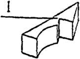
附图1是边模块的立体示意图,Accompanying drawing 1 is the three-dimensional schematic diagram of edge module,
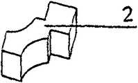
附图2是芯模块的立体示意图,Accompanying
附图3是由两只互为镜像的边模块组成的芯模块的立体示意图;Accompanying
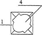
附图4是四只边模块围合成完整的浇注模具单元示意图,Accompanying
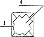
附图5是四只芯模块围合成完整的浇注模具单元示意图;Accompanying
图6是四只边模块围合成完整的浇注模具单元示意图,Fig. 6 is a schematic diagram of a complete pouring mold unit surrounded by four side modules,
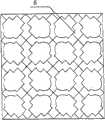
附图7是由浇注模具单元排列成的单元式浇注模具组示意图,Accompanying
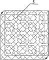
附图8是模块式浇注模具组示意图;Accompanying
附图9是由一种芯模块和一种边模块构成的对称工件模块式浇注模具组示意图,Accompanying
附图10是由两种芯模块和四种两两互为镜像的边模块构成的不对称工件模块式浇注模具组示意图;Accompanying drawing 10 is a schematic diagram of an asymmetric workpiece modular pouring mold group composed of two kinds of core modules and four kinds of side modules that are mirror images of each other;
附图11是对称工件模块式浇注模具组拼装示意图,Accompanying drawing 11 is the assembling schematic diagram of symmetrical workpiece modular pouring mold group,
附图12是不对称工件模块式浇注模具组拼装示意图;Accompanying drawing 12 is the schematic diagram of assembling of asymmetric workpiece modular pouring mold group;
附图13是浇注模具组定位示意图;Accompanying drawing 13 is a schematic diagram of casting mold group positioning;
附图14是按照模具单元拼装方法将底层浇注模具单元拼装完成示意图,Accompanying drawing 14 is according to the mold unit assembling method to complete the schematic diagram of assembling the bottom pouring mold unit,
附图15是第二层浇注模具单元直接拼装在第一层浇注模具单元之上的示意图,Accompanying drawing 15 is the schematic diagram that the second layer of pouring mold unit is directly assembled on the first layer of casting mold unit,
附图16是多层浇注模具单元依次层层拼装的示意图;Accompanying drawing 16 is the schematic diagram of layer by layer assembly of multi-layer casting mold unit;
附图17是非柱形浇注工件平面示意图,Accompanying drawing 17 is a schematic plan view of a non-cylindrical pouring workpiece,
附图18是非柱形浇注工件立体示意图,Accompanying drawing 18 is the three-dimensional schematic diagram of non-cylindrical pouring workpiece,
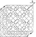
附图19是按照浇注模具组的拼装方法先将底层浇注模具组拼装完成示意图,Accompanying drawing 19 is according to the assembling method of pouring mold set first the bottom pouring mold set is assembled and completed schematic diagram,
附图20是第二层浇注模具组直接拼装在第一层浇注模具组之上的示意图,Accompanying drawing 20 is the schematic diagram that the second layer of pouring mold group is directly assembled on the first layer of casting mold group,
附图21是多层浇注模具组依次层层拼装的示意图。Accompanying drawing 21 is the schematic diagram that multi-layer pouring mold group is assembled layer by layer.
图中的1是边模块、2是芯模块、3是由两只互为镜像的边模块组成的芯模块、4是浇注模具单元、5是单元式浇注模具组、6是模块式浇注模具组、7是侧定位板、8是定位块、9是浇注工件。In the figure, 1 is a side module, 2 is a core module, 3 is a core module composed of two mirrored side modules, 4 is a casting mold unit, 5 is a unit casting mold group, and 6 is a modular casting mold group , 7 is a side positioning plate, 8 is a positioning block, and 9 is a pouring workpiece.
具体实施方式Detailed ways
对照附图4、5、6,其结构是每个浇注工件可由四只边模块1或四只芯模块2围合成一副完整的浇注模具单元4;With reference to accompanying
对照附图7、8,多个浇注模具单元4可以组合成单元式浇注模具组5(见附图7);或由多组边模块1和芯模块2组合成模块式浇注模具组6(见附图8)。模块式浇注模具组6中的任一芯模块2既是本浇注模具单元4的1/4模块,同时也是相邻浇注模具单元4的1/4模块(见附图8)。浇注模具组5、浇注模具组6的四周用侧定位板7和定位块8或其它方式固定(见附图13)。With reference to accompanying
实施例,工件仅采用沿对角线方向排列法,以十六个模具单元排列成的组合模具示例。In the embodiment, the workpieces are only arranged in a diagonal direction, and an example of a combined mold with sixteen mold units is arranged.
组合式浇注模具制造方法,其特征是分一、平面模具图绘制,二、模块制造,三、模具拼装方法。The combined pouring mold manufacturing method is characterized in that: first, planar mold drawing, second, module manufacturing, and third, mold assembling method.
所述的一、平面模具图绘制:绘制一个大于工件对角线的矩形;用两条直线分别连接该矩形的四个对角;将工件的平面图置入该矩形的中心,构成浇注模具单元4,(见附图4、5、6);依据相邻工件镜像排列的方式(也可以任意排列,但是这种镜像排列方式需要的模块种类最少,因此也最经济),按照实际所需工件数量(长×宽必须是模具单元数的整数倍)将多个浇注模具单元4排列成一个组合矩形,形成单元式浇注模具组(见附图7);删除组合矩形中的横线和竖线,此时,其余图形所示即为模块式浇注模具组所需的模块组合(见附图8)。其中,沿外轮廓排列的为边模块1;中心部分除工件图形以外的图形即为芯模块2(见附图8),或用两只互为镜像的边模块1组合成芯模块3(见附图3,附图7);将上述边模块1和芯模块2加上高度即为实际所需的组模用的模块。工件是对称的,至少可由一种芯模块2和一种边模块1组成模块式浇注模具组6(见附图9);工件是非对称的,至少可由两种芯模块2和四种两两互为镜像的边模块1构成模块式浇注模具组6(见附图10);工件是非柱形的,则需分层绘制模具图(绘制方法同上)。The first, planar mold drawing: draw a rectangle larger than the diagonal of the workpiece; connect the four diagonal corners of the rectangle with two straight lines; put the plan view of the workpiece into the center of the rectangle to form a
二、模块制造:2. Module manufacturing:
边模块和芯模块可通过“实物制取法”、“切割法”、“机械加工法”、“注塑、挤塑制取法”等传统加工方法制造:其中Side modules and core modules can be manufactured by traditional processing methods such as "material production method", "cutting method", "machining method", "injection molding and extrusion molding method": among them
(1)“实物制取法”:首先,依据模块设计图按照实际尺寸制作边模块或芯模块实物,再采用“翻砂制模法”、“石膏制模法”、“橡胶制模法”、“硅胶制模法”、“树脂制模法”或“玻璃钢制模法”等方法加工用于制作模块的模具,然后按照传统浇注方法将所需的浇注原料倒入拼合好的浇注模具,待材料凝固后开模,即可获得所需的边模块或芯模块;(1) "Preparation method in kind": First, make the side module or core module in kind according to the actual size according to the module design drawing, and then use the "sand casting method", "gypsum molding method", "rubber molding method", "Silicone molding method", "resin molding method" or "glass fiber reinforced plastic molding method" and other methods to process the mold used to make the module, and then pour the required casting materials into the spliced casting mold according to the traditional pouring method, and wait for After the material is solidified, the mold is opened to obtain the required side module or core module;
(2)“切割制取法”:依据模块设计图采用机械切割、水刀切割、激光切割、等离子切割等方法直接制取边模块和芯模块,或先制取浇注模块用模具,然后按照传统浇注方法将所需的浇注原料倒入拼合好的浇注模具,待材料凝固后开模,即可获得所需的边模块或芯模块;(2) "Cutting method": according to the module design drawing, use mechanical cutting, water jet cutting, laser cutting, plasma cutting and other methods to directly prepare side modules and core modules, or first prepare molds for pouring modules, and then cast according to traditional methods Method Pour the required pouring materials into the spliced pouring mold, and open the mold after the material is solidified to obtain the required side modules or core modules;
(3)“机械加工法”:依据模块设计图采用机械加工的方法直接制取边模块和芯模块,或先制取浇注模块用模具,然后按照传统浇注方法将所需的浇注原料倒入拼合好的浇注模具,待材料凝固后开模,即可获得所需的边模块或芯模块;(3) "Machining method": According to the module design drawing, the side module and the core module are directly produced by mechanical processing, or the mold for the casting module is first produced, and then the required casting materials are poured into the joint according to the traditional casting method After the material is solidified, the mold is opened to obtain the required side module or core module;
(4)“注塑、挤塑制取法”:依据模块设计图设计出相应的注塑或挤塑模具,利用机械加工的方法制造注塑或挤塑模具,然后再利用注塑或挤塑机生产出所需的塑料边模块或芯模块;(4) "Injection molding, extrusion molding production method": Design the corresponding injection molding or extrusion molding mold according to the module design drawing, use the method of mechanical processing to manufacture the injection molding or extrusion molding mold, and then use the injection molding or extrusion molding machine to produce the finished product. Required plastic side modules or core modules;
三、模具拼装方法:3. Mold assembly method:
浇注单件工件时,分浇注柱形工件模具单元的平面拼装法和浇注非柱形工件模具单元的分层拼装法;浇注多件工件时,分浇注柱形工件浇注模具组的平面拼装法以及浇注非柱形工件浇注模具组的分层拼装法。When pouring a single workpiece, the planar assembly method of pouring cylindrical workpiece mold units and the layered assembly method of pouring non-cylindrical workpiece mold units; A layered assembly method for pouring non-cylindrical workpiece casting mold groups.
所述的浇注单件工件中的浇注柱形工件模具单元的平面拼装法:(1)对称工件浇注模具单元的拼装方法,是按照同种模块对面首尾相对、相邻模块或相邻镜像模块镜像端直角相接排列,将边模块或一组互为镜像的边模块平面向外组合成模具单元(见附图4);(2)非对称工件浇注模具单元的拼装方法,是按照将同种类镜像模块镜像端相邻排列、直角相接,再将两类边模块相对拼合,将两组边模块平面向外组合成浇注模具单元(见附图6);The plane assembling method of the pouring cylindrical workpiece mold unit in the pouring single-piece workpiece: (1) the assembling method of the symmetrical workpiece pouring mold unit is based on the opposite end-to-end of the same type of modules, the mirror image of adjacent modules or adjacent mirrored modules The ends are arranged at right angles, and the side modules or a group of side modules that are mirror images of each other are combined to form a mold unit (see Figure 4); (2) The assembly method of the asymmetric workpiece casting mold unit is based on the same type The mirror ends of the mirror modules are arranged adjacent to each other and connected at right angles, and then the two types of side modules are combined relatively, and the two sets of side modules are combined outwardly to form a pouring mold unit (see Figure 6);
所述的浇注单件工件中的浇注非柱形工件模具单元的分层拼装法:按照浇注模具单元的拼装方法先将底层浇注模具单元拼装完成(见附图14);再将第二层浇注模具单元直接拼装在第一层浇注模具单元之上(见附图15);多层浇注模具单元,依次层层拼装(见附图16),直至完成所需的浇注模具单元组合(多层浇注模具单元既可以全模拼装完整后再浇注,也可以分层拼装、分层浇注)。The layered assembly method of casting non-cylindrical workpiece mold units in the casting single-piece workpiece: according to the assembling method of casting mold units, the bottom casting mold units are first assembled (see accompanying drawing 14); then the second layer of casting The mold unit is directly assembled on the first layer of casting mold unit (see accompanying drawing 15); the multilayer casting mold unit is assembled layer by layer (see accompanying drawing 16) until the required combination of casting mold units (multilayer casting The mold unit can be fully assembled and then poured, or it can be assembled in layers and poured in layers).
所述的浇注多件工件中的浇注柱形工件浇注模具组的平面拼装法:(1)对称工件浇注模具组的拼装方法,沿侧定位板将两镜像边模块镜像端直角相接,且平面向外首首相连、尾尾相接依次排列;相邻芯模块间形状相同的一端角对角拼合,同一列或同一行模块首首相连、尾尾相接依次拼装(见附图11)(模块结合部也可设计成其它形状,但拼模效率较低);(2)不对称浇注模具组的平面拼装法:同类型边模块相向排列在矩形模具的两个对边,另一类型的边模块相向排列在矩形模具的另两个对边,同侧边模块首首相连、尾尾相接;不同类型的芯模块相间排列(见附图12),同一列或同一行模块同样是首首相连、尾尾相接。The plane assembling method of the pouring cylindrical workpiece pouring mold set in the pouring multiple workpieces: (1) the assembling method of the symmetrical workpiece pouring mold set, the mirror image ends of the two mirror image side modules are connected at right angles along the side positioning plate, and the plane Connected head-to-head and tail-to-tail outward; adjacent core modules of the same shape are assembled diagonally, and modules in the same column or row are assembled head-to-head and tail-to-tail (see Figure 11) ( The module junction can also be designed into other shapes, but the mould-making efficiency is low); (2) Plane assembly method of asymmetric casting mold group: the same type of side modules are arranged on the two opposite sides of the rectangular mould, and the other type The side modules are arranged oppositely on the other two opposite sides of the rectangular mold, and the same side modules are connected head to head and tail to tail; different types of core modules are arranged alternately (see Figure 12), and the modules in the same column or row are also the first First connected, tail connected.
所述的浇注多件工件中的浇注非柱形工件浇注模具组的分层拼装法:按照浇注模具组的拼装方法先将底层浇注模具组拼装完成(见附图19);再将第二层浇注模具组直接拼装在第一层浇注模具组之上(见附图20);多层浇注模具组,依次层层拼装(见附图21),直至组成所需的浇注模具组合(多层浇注模具组既可以全模拼装完整后再浇注,也可以分层拼装、分层浇注)。由于模具组四周设有侧定位板7和定位块8固定,且相邻模块间的结合部采用角对角的方式组模,形成相互“咬合”关系,模块间不会产生位移和形变,因此不会发生层与层之间定位不准确的现象,所以,层与层之间固定与否对所铸工件的精度并无影响。The layered assembly method of casting non-cylindrical workpiece pouring mold sets in the pouring multiple workpieces: according to the assembling method of pouring mold sets, the bottom casting mold set is first assembled (see accompanying drawing 19); and then the second layer The casting mold group is directly assembled on the first layer of casting mold group (see accompanying drawing 20); the multi-layer casting mold group is assembled layer by layer (see accompanying drawing 21) until the required casting mold combination is formed (multilayer casting The mold group can either be fully assembled and then poured, or it can be assembled in layers and poured in layers). Since the
Claims (4)
Priority Applications (1)
| Application Number | Priority Date | Filing Date | Title |
|---|---|---|---|
| CNB2006100974517ACN100556579C (en) | 2006-11-09 | 2006-11-09 | Combined casting mold and its manufacturing method |
Applications Claiming Priority (1)
| Application Number | Priority Date | Filing Date | Title |
|---|---|---|---|
| CNB2006100974517ACN100556579C (en) | 2006-11-09 | 2006-11-09 | Combined casting mold and its manufacturing method |
Publications (2)
| Publication Number | Publication Date |
|---|---|
| CN1970193A CN1970193A (en) | 2007-05-30 |
| CN100556579Ctrue CN100556579C (en) | 2009-11-04 |
Family
ID=38111322
Family Applications (1)
| Application Number | Title | Priority Date | Filing Date |
|---|---|---|---|
| CNB2006100974517AExpired - Fee RelatedCN100556579C (en) | 2006-11-09 | 2006-11-09 | Combined casting mold and its manufacturing method |
Country Status (1)
| Country | Link |
|---|---|
| CN (1) | CN100556579C (en) |
Families Citing this family (5)
| Publication number | Priority date | Publication date | Assignee | Title |
|---|---|---|---|---|
| CN102198487B (en)* | 2010-04-20 | 2013-01-09 | 机械科学研究总院先进制造技术研究中心 | Fitting-structure-based dieless assembly molding method |
| CN102059778B (en)* | 2010-11-15 | 2014-05-07 | 先锐模具配件(东莞)有限公司 | Method for simultaneously producing multiple products and forming die |
| CN103213405B (en)* | 2013-04-17 | 2015-05-13 | 田波 | 3D printer capable of being produced in mass mode and three-dimensional manufacturing method |
| CN111688239A (en)* | 2020-06-03 | 2020-09-22 | 洛阳双瑞风电叶片有限公司 | Splicing type wind power blade web plate die |
| CN111907003A (en)* | 2020-07-29 | 2020-11-10 | 东莞市华丽丰电子科技有限公司 | Processing device and processing technology for colorful effect of back shell of smart phone |
Citations (7)
| Publication number | Priority date | Publication date | Assignee | Title |
|---|---|---|---|---|
| GB1279297A (en)* | 1969-06-24 | 1972-06-28 | Howmet Corp | Ceramic gang mold |
| US4072180A (en)* | 1975-02-22 | 1978-02-07 | W. H. Booth & Co. Limited | Process and mould for casting multiple articles |
| CN1116569A (en)* | 1994-08-08 | 1996-02-14 | 苟华强 | Method for casting many products |
| US5524699A (en)* | 1994-02-03 | 1996-06-11 | Pcc Composites, Inc. | Continuous metal matrix composite casting |
| CN2574805Y (en)* | 2002-06-21 | 2003-09-24 | 段晓鸣 | Tilting type molten iron desulfurizing car |
| CN1748903A (en)* | 2005-10-24 | 2006-03-22 | 姜庆志 | Stack cast ball and cast forging mould of production line |
| CN200984623Y (en)* | 2006-11-09 | 2007-12-05 | 南京蓝捷德科技有限公司 | Combined type casting mould |
- 2006
- 2006-11-09CNCNB2006100974517Apatent/CN100556579C/ennot_activeExpired - Fee Related
Patent Citations (7)
| Publication number | Priority date | Publication date | Assignee | Title |
|---|---|---|---|---|
| GB1279297A (en)* | 1969-06-24 | 1972-06-28 | Howmet Corp | Ceramic gang mold |
| US4072180A (en)* | 1975-02-22 | 1978-02-07 | W. H. Booth & Co. Limited | Process and mould for casting multiple articles |
| US5524699A (en)* | 1994-02-03 | 1996-06-11 | Pcc Composites, Inc. | Continuous metal matrix composite casting |
| CN1116569A (en)* | 1994-08-08 | 1996-02-14 | 苟华强 | Method for casting many products |
| CN2574805Y (en)* | 2002-06-21 | 2003-09-24 | 段晓鸣 | Tilting type molten iron desulfurizing car |
| CN1748903A (en)* | 2005-10-24 | 2006-03-22 | 姜庆志 | Stack cast ball and cast forging mould of production line |
| CN200984623Y (en)* | 2006-11-09 | 2007-12-05 | 南京蓝捷德科技有限公司 | Combined type casting mould |
Also Published As
| Publication number | Publication date |
|---|---|
| CN1970193A (en) | 2007-05-30 |
Similar Documents
| Publication | Publication Date | Title |
|---|---|---|
| CN100556579C (en) | Combined casting mold and its manufacturing method | |
| CN106475518B (en) | For casting the sand mold and its manufacturing method of rotary structure casting | |
| CN104401002A (en) | 3D printing-based curved microlens array manufacturing method | |
| CN104802339A (en) | Quick precision mold preparation method | |
| CN109822909A (en) | An optimization algorithm for FDM 3D printer | |
| CN101315436A (en) | Method for manufacturing super-large silicon carbide space mirror body | |
| CN109822787B (en) | Combined die for forming water-soluble pyramid dot matrix core die | |
| CN200984623Y (en) | Combined type casting mould | |
| CN113987822A (en) | Design method of isotropic negative Poisson's ratio material | |
| CN109663920B (en) | Solid-phase additive manufacturing method of laminated structure | |
| EP3946944B1 (en) | High productivity system for printing precision articles | |
| CN218591821U (en) | Supporting structure | |
| CN213033581U (en) | PU back mould mold core model casting removes shrinkage porosity mechanism | |
| CN107838420B (en) | Method for 3D printing by using melting bed and 3D printing system | |
| CN106284817B (en) | Plane self-locking module system and manufacturing method and device | |
| CN211415942U (en) | High-precision rubber combined die | |
| CN102096167B (en) | lens module | |
| CN111251425B (en) | A forming device and a manufacturing method of a gypsum mold | |
| CN111284016A (en) | A kind of complex mold design and demoulding method based on magnetic force | |
| CN113275572B (en) | Lightweight metal structure, metal member and preparation method thereof | |
| CN103240845B (en) | A kind of combination lamination embedded type mould | |
| CN209491690U (en) | A kind of shaped piece template assembly tooling | |
| CN208341536U (en) | A kind of mould for forming shell of headphone | |
| CN221873217U (en) | A support structure for additive manufacturing | |
| CN223186816U (en) | Closing-in annular air inlet channel forming die |
Legal Events
| Date | Code | Title | Description |
|---|---|---|---|
| C06 | Publication | ||
| PB01 | Publication | ||
| C10 | Entry into substantive examination | ||
| SE01 | Entry into force of request for substantive examination | ||
| C14 | Grant of patent or utility model | ||
| GR01 | Patent grant | ||
| CF01 | Termination of patent right due to non-payment of annual fee | Granted publication date:20091104 Termination date:20141109 | |
| EXPY | Termination of patent right or utility model |