CN100555549C - Enhanced Electron Backscattering in X-ray Tubes - Google Patents
Enhanced Electron Backscattering in X-ray TubesDownload PDFInfo
- Publication number
- CN100555549C CN100555549CCNB2004800150450ACN200480015045ACN100555549CCN 100555549 CCN100555549 CCN 100555549CCN B2004800150450 ACNB2004800150450 ACN B2004800150450ACN 200480015045 ACN200480015045 ACN 200480015045ACN 100555549 CCN100555549 CCN 100555549C
- Authority
- CN
- China
- Prior art keywords
- ray
- window
- transmissive window
- ray tube
- anode
- Prior art date
- Legal status (The legal status is an assumption and is not a legal conclusion. Google has not performed a legal analysis and makes no representation as to the accuracy of the status listed.)
- Expired - Fee Related
Links
Images


Classifications
- H—ELECTRICITY
- H01—ELECTRIC ELEMENTS
- H01J—ELECTRIC DISCHARGE TUBES OR DISCHARGE LAMPS
- H01J35/00—X-ray tubes
- H01J35/02—Details
- H01J35/04—Electrodes ; Mutual position thereof; Constructional adaptations therefor
- H01J35/08—Anodes; Anti cathodes
- H01J35/10—Rotary anodes; Arrangements for rotating anodes; Cooling rotary anodes
- H—ELECTRICITY
- H01—ELECTRIC ELEMENTS
- H01J—ELECTRIC DISCHARGE TUBES OR DISCHARGE LAMPS
- H01J35/00—X-ray tubes
- H01J35/02—Details
- H01J35/16—Vessels; Containers; Shields associated therewith
- H01J35/18—Windows
- H—ELECTRICITY
- H01—ELECTRIC ELEMENTS
- H01J—ELECTRIC DISCHARGE TUBES OR DISCHARGE LAMPS
- H01J2235/00—X-ray tubes
- H01J2235/12—Cooling
- H01J2235/122—Cooling of the window
- H—ELECTRICITY
- H01—ELECTRIC ELEMENTS
- H01J—ELECTRIC DISCHARGE TUBES OR DISCHARGE LAMPS
- H01J2235/00—X-ray tubes
- H01J2235/16—Vessels
- H01J2235/165—Shielding arrangements
- H01J2235/168—Shielding arrangements against charged particles
- H—ELECTRICITY
- H01—ELECTRIC ELEMENTS
- H01J—ELECTRIC DISCHARGE TUBES OR DISCHARGE LAMPS
- H01J2235/00—X-ray tubes
- H01J2235/18—Windows, e.g. for X-ray transmission
- H01J2235/183—Multi-layer structures
Landscapes
- X-Ray Techniques (AREA)
- Image-Pickup Tubes, Image-Amplification Tubes, And Storage Tubes (AREA)
Abstract
Description
Translated fromChinese本发明涉及金属框架X射线管,尤其是涉及一种适合于降低X射线透射窗和该窗周围的金属框架的发热的X射线管。本发明与医疗诊断成像系统结合在一起而获得应用,并且将特别对此进行描述。The present invention relates to a metal frame X-ray tube, and more particularly to an X-ray tube suitable for reducing the heating of an X-ray transmission window and a metal frame around the window. The present invention finds application in connection with medical diagnostic imaging systems and will be particularly described herein.
传统的医疗成像系统对X射线的使用包括射线照相、荧光透视和计算机体层摄影(CT)。在射线照相中,病人的静止阴影图像形成在X射线胶片上;在荧光透视中,低强度的X射线穿过病人后撞击在荧光屏上而形成可见的实时遮光图像;在计算机体层摄影中,用绕病人身体转动的高功率X射线管产生的X射线来电重构出整个病人图像。Traditional medical imaging systems use of X-rays include radiography, fluoroscopy, and computed tomography (CT). In radiography, a still shadow image of the patient is formed on X-ray film; in fluoroscopy, low-intensity X-rays pass through the patient and impinge on a fluorescent screen to form a visible real-time shading image; in computed tomography, The whole patient image is reconstructed by the X-ray electricity generated by the high-power X-ray tube rotating around the patient's body.
该X射线管组件通常包括衬铅的壳体,该壳体容纳了持有旋转阳极和固定阴极的真空外壳或X射线插入件。该X射线插入件可以是金属外壳或金属框架,铍X射线透射窗安装或硬焊在该金属外壳或金属框架上上,以允许来自于X射线插入件的X射线透射出来。同样地,在该壳体内限定了X射线输出窗,其与X射线插入件的铍窗对齐,使得X射线可以直接穿过该铍窗和X射线输出窗。冷却油在该X射线插入件和该壳体之间循环。The X-ray tube assembly typically includes a lead-lined housing that houses a vacuum envelope or X-ray insert that holds a rotating anode and a stationary cathode. The x-ray insert may be a metal housing or frame onto which a beryllium x-ray transmissive window is mounted or brazed to allow transmission of x-rays from the x-ray insert. Likewise, an x-ray output window is defined within the housing that is aligned with the beryllium window of the x-ray insert such that x-rays can pass directly through the beryllium window and the x-ray output window. Cooling oil circulates between the X-ray insert and the housing.
通常,该阴极具有供加热电流通过的阴极丝。该电流充分加热该丝以致于发射出电子云,即发生热电子发射。在位于真空外壳内的阴极和阳极之间施加100~200kV数量级的高电势。该电势使得电子通过该外壳内部的真空区域从阴极流到阳极。容纳有阴极丝的阴极聚焦杯将电子聚焦阳极上的小区域或聚焦斑上。该电子束以足够的能量撞击阳极以致于产生X射线。所产生的X射线的一部分穿过该外壳的X射线透射窗到达连接在X射线管壳体上的限束装置或准直仪。该限束装置调节朝向于病人或受检测对象的X射线束的尺寸和形状,由此而允许重构出病人或对象的图像。Typically, the cathode has a cathode filament through which a heating current is passed. The current heats the filament sufficiently that a cloud of electrons is emitted, ie, thermionic emission occurs. A high potential of the order of 100-200 kV is applied between the cathode and the anode inside the vacuum envelope. This potential causes electrons to flow from the cathode to the anode through the vacuum region inside the enclosure. The cathode focusing cup, which houses the cathode filament, focuses the electrons onto a small area or spot on the anode. The electron beam strikes the anode with sufficient energy to generate X-rays. A part of the generated X-rays passes through the X-ray transmission window of the housing to a beam limiting device or a collimator connected to the X-ray tube housing. The beam limiting device adjusts the size and shape of the X-ray beam directed towards the patient or object under examination, thereby allowing reconstruction of an image of the patient or object.
在产生X射线的过程中,当一次电子束撞击阳极靶的表面时,一部分电子透入该固定中并且与靶材料的晶格原子核和电子相互作用。主要是通过与外层电子的相互作用而产生激发和电离。在该固体中游离的电子通过该过程朝着表面移动,而这些电子中的一部分将会逃逸为真二次电子。真二次电子通常具有几eV的能级。通常,能级少于50eV的电子被称为二次电子。还有可能是,在固体内部损失了其一部分能量的一次电子被散射回该表面。如果这样的一次电子还剩下有足够的能量,那么它可以穿过表面势垒并逃逸,结果就形成了卢瑟福散射。此外,一部分一次电子从固体表面弹性散射。属于后两类的电子的能量在50eV和电子束的一次能级之间。During the generation of X-rays, when a primary electron beam strikes the surface of the anode target, a portion of the electrons penetrates into this fixation and interacts with the lattice nuclei and electrons of the target material. Excitation and ionization are mainly generated through the interaction with the outer electrons. Electrons that are free in the solid move towards the surface by this process, and some of these electrons will escape as true secondary electrons. True secondary electrons generally have energy levels of several eV. Generally, electrons with an energy level of less than 50 eV are called secondary electrons. It is also possible that the primary electrons, which have lost some of their energy inside the solid, are scattered back to the surface. If such a primary electron has enough energy left, it can pass through the surface barrier and escape, resulting in Rutherford scattering. In addition, a part of the primary electrons is elastically scattered from the solid surface. Electrons belonging to the latter two classes have energies between 50 eV and the primary energy level of the electron beam.
一个人可以将离开该表面的这三种可识别类的电子区分为:(i)弹性反射一次电子,(ii)非弹性反射一次电子,和(iii)真二次电子。类别(i)和(ii)通常被称为反向散射电子。One can distinguish these three identifiable classes of electrons leaving the surface as: (i) elastically reflecting primary electrons, (ii) inelastically reflecting primary electrons, and (iii) true secondary electrons. Classes (i) and (ii) are commonly referred to as backscattered electrons.
对于高于30eV的电子能量,靶材料发射二次电子的能量损失是可以忽略的。在类别(i)和(ii)中反向散射的能量损失对于X射线管中X射线透射窗和框架的发热是更重要的。由这些反向散射电子造成的金属框架的窗区域周围的发热是限制金属框架X射线管以更高功率水平运行的一个因素。For electron energies above 30 eV, the energy loss of the target material for emitting secondary electrons is negligible. Backscattered energy losses in categories (i) and (ii) are more important for heating of the X-ray transmission window and frame in the X-ray tube. The heating around the window area of the metal frame caused by these backscattered electrons is a factor that limits the operation of metal frame X-ray tubes at higher power levels.
这些从靶上反向散射的电子可以具有50eV到全阴极电势之间的能量。然而,典型的反向散射电子的能量大约为一次束中电子能量的一半。这些电子撞击X射线管的其它区域。其大部分朝着接地的X射线透射窗以及窗周围的金属管外壳(或框架)反射或加速,并随后撞击它们。一些电子依靠全阴极电势产生的力被加速。These backscattered electrons from the target can have energies between 5OeV and the full cathode potential. However, typical backscattered electrons have about half the energy of the electrons in the primary beam. These electrons strike other areas of the x-ray tube. Most of it is reflected or accelerated towards the grounded x-ray transmissive window and the metal tube casing (or frame) around the window, and then hits them. Some electrons are accelerated by the force generated by the full cathode potential.
当从靶反向散射或者从阴极丝直接发射的电子与该窗/框架进行非弹性对撞时,其动能转换成导致该窗和周围的框架发热的热量。When electrons backscattered from the target or emitted directly from the cathode filament inelastically collide with the window/frame, their kinetic energy is converted into heat which causes the window and surrounding frame to heat up.
该X射线发射铍窗接受了最高强度的反向散射电子和二次电子加热,这是因为该窗更靠近于阳极上的聚焦斑。当该窗不足够冷时,该热量会损害该X射线插入件的X射线透射窗和金属框架之间的硬焊接合,从而使得该X射线管出现故障。此外,邻近于该窗的冷却剂会沸腾并在该窗上留下残炭。这样的覆盖层是不希望有的,这是因为它会使X射线图像的质量退化。The x-ray emitting beryllium window receives the highest intensity of backscattered and secondary electron heating because it is closer to the focal spot on the anode. When the window is not cool enough, the heat can damage the brazed bond between the x-ray transparent window of the x-ray insert and the metal frame, causing the x-ray tube to fail. In addition, coolant adjacent to the window can boil and leave char residue on the window. Such an overlay is undesirable because it degrades the quality of the x-ray image.
现在有一种需求是提供X射线管来产生更高功率的曝光和更短的成像时间,随着这种需求,撞击阳极的电子束的强度持续提高。可惜的是,这又会提高二次和反向散射电子的轰击量,由此而难于在该窗和金属外壳之间提供可靠的气密连接。The intensity of the electron beam striking the anode continues to increase as there is a need to provide X-ray tubes that produce higher power exposures and shorter imaging times. Unfortunately, this again increases the bombardment of secondary and backscattered electrons, thereby making it difficult to provide a reliable airtight connection between the window and the metal housing.
在转让给Siemens Aktiengesellschaft的美国专利5511104中记载了一种用来降低在窗和金属框架之间的接合部出现的二次电子轰击量的公知方法。该104专利提供了处于阳极电势的第一电极和处于阴极电势的第二电极,它们布置成使得从阳极放射出的二次电子必须穿过位于第一和第二电极之间的空间以便到达该窗。由于穿过该空间的二次电子被吸引到处于阳极电势的电极,因此很少有二次和反向散射电子能到达该窗,从而降低了该窗和该外壳之间的接合部的发热。104专利的一个缺点是用这种设计构造的X射线管通常局限于单端设计,例如,其中阳极处于接地电势而阴极处于-150000V。如果一种双极布置与104专利所述的设计结合在一起使用,其中阳极助于正电压电势(即+75000V)而阴极处于负电压电势(即-75000V),那么就难于将电极设置成在电极和阳极和/或阴极之间不出现起弧。A known method for reducing the amount of secondary electron bombardment occurring at the junction between the window and the metal frame is described in US Patent 5,511,104 assigned to Siemens Aktiengesellschaft. The '04 patent provides a first electrode at anodic potential and a second electrode at cathodic potential arranged such that secondary electrons emitted from the anode must pass through the space between the first and second electrodes in order to reach the window. Since secondary electrons passing through the space are attracted to the electrode at anode potential, few secondary and backscattered electrons reach the window, reducing heating at the junction between the window and the housing. One disadvantage of the '04 patent is that X-ray tubes constructed with this design are generally limited to single-ended designs, eg, where the anode is at ground potential and the cathode is at -150,000V. If a bipolar arrangement is used in conjunction with the design described in the '04 patent, where the anode contributes to a positive voltage potential (i.e., +75000V) and the cathode is at a negative voltage potential (i.e., -75000V), it becomes difficult to place the electrodes at Arcing does not occur between the electrodes and the anode and/or cathode.
因此,就需要一种装置来降低由该窗和金属框架外壳处的反向散射和二次电子轰击所产生的发热量,从而克服上文所述的缺陷。Therefore, there is a need for a device to reduce the heat generated by backscattering and secondary electron bombardment at the window and metal frame casing, thereby overcoming the above-mentioned disadvantages.
如果能使入射到该窗和该窗周围的框架上的更大部分电子作为再次反向散射的电子而被反射,那么这些转化成框架中热量的电子动量将会减少。本发明指向一种X射线管结构,该X射线管结构满足这样的需要,即提供一种X射线透射窗区域来在X射线产生过程中降低由反向散射电子引起的局部发热。If a greater fraction of electrons incident on the window and the frame surrounding the window could be made to be reflected as re-backscattered electrons, the momentum of these electrons, which is converted to heat in the frame, would be reduced. The present invention is directed to an X-ray tube structure which fulfills the need to provide an X-ray transparent window region to reduce localized heating caused by backscattered electrons during X-ray generation.
应用本发明原理的装置包括限定了靶的阳极以及与该阳极成可操作关系以便产生X射线的阴极组件。一真空外壳包围该阳极和阴极。该真空外壳包括金属框架部分,构成该金属框架部分的材料具有一反向散射系数。X射线透射窗以真空密闭方式与真空外壳的金属框架部分连接。构成该X射线透射窗的材料具有一反向散射系数。在X射线透射窗以及X射线透射窗周围的真空外壳的金属框架部分上沉积反向散射层。该反向散射层的反向散射系数大于该窗和金属框架两者的反向散射系数。Apparatus employing the principles of the present invention includes an anode defining a target and a cathode assembly in operative relationship with the anode for generating x-rays. A vacuum envelope surrounds the anode and cathode. The vacuum enclosure includes a metal frame portion made of a material having a backscatter coefficient. The X-ray transmission window is connected to the metal frame part of the vacuum envelope in a vacuum-tight manner. The material constituting the X-ray transmission window has a backscattering coefficient. A backscattering layer is deposited on the X-ray transmissive window and on the metal frame portion of the vacuum envelope surrounding the X-ray transmissive window. The backscattering coefficient of the backscattering layer is greater than both the backscattering coefficients of the window and the metal frame.
按照应用本发明原理的装置的另一方面,构成该反向散射层的材料具有至少为35的原子序数(Z)。In accordance with another aspect of a device employing principles of the present invention, the material comprising the backscattering layer has an atomic number (Z) of at least 35.
按照应用本发明原理的装置的另一方面,构成该反向散射层的材料具有至少为0.40的反向散射系数According to another aspect of the device employing the principles of the present invention, the material comprising the backscattering layer has a backscattering coefficient of at least 0.40
应用本发明原理的装置的另一方面,对于由X射线透射窗和反向散射层引起的总衰减,保持X射线透过X射线透射窗的透射率高于预定的阈值。Another aspect of an apparatus employing the principles of the present invention maintains the transmission of X-rays through the X-ray transparent window above a predetermined threshold for the total attenuation caused by the X-ray transparent window and the backscatter layer.
按照应用本发明原理的装置的又一方面,施加到X射线透射窗的反向散射层的厚度为至少1微米。在应用本发明原理的装置更受限的方面中,施加到X射线透射窗的反向散射层的厚度小于9.5微米。According to yet another aspect of a device employing principles of the present invention, the thickness of the backscattering layer applied to the x-ray transmissive window is at least 1 micron. In a more limited aspect of a device employing the principles of the invention, the thickness of the backscattering layer applied to the x-ray transmissive window is less than 9.5 microns.
本发明的一个优点在于它在X射线管的运行过程中降低了该窗区域的局部发热。An advantage of the invention is that it reduces local heating in the window region during operation of the X-ray tube.
本发明的另一个优点是提高了该X射线管的寿命。Another advantage of the present invention is that the lifetime of the X-ray tube is increased.
本发明的又一个优点在于提高了该X射线管的可靠性和性能。Yet another advantage of the present invention is that the reliability and performance of the X-ray tube is improved.
应用本发明原理的装置和方法提供了前述特征以及在下文记载和在权利要求书中特别指出的其它特征。下文的说明和附图说明了应用本发明原理的示例性实施例。可以理解,应用本发明原理的不同实施例可以以各种部件和部件的设置来成形。这些记载的实施例只是示出了可以利用本发明原理的各种方式中一些方式。附图只是为了说明应用本发明原理的装置的优选实施例,并不是用来限制本发明。Apparatus and methods employing the principles of the invention provide the foregoing features and others as described hereinafter and particularly pointed out in the claims. The following description and drawings illustrate exemplary embodiments employing the principles of the invention. It is to be understood that different embodiments employing the principles of the invention may be formed in various components and arrangements of components. These described embodiments illustrate but a few of the various ways in which the principles of the invention may be employed. The accompanying drawings are only intended to illustrate preferred embodiments of devices applying the principles of the present invention, and are not intended to limit the present invention.
参考附图,基于下文对本发明优选实施例的详细说明,本发明的前述和其它特征以及优点对于本发明所属领域的技术人员来说将变得明显。The foregoing and other features and advantages of the present invention will become apparent to those skilled in the art to which the present invention pertains based on the following detailed description of preferred embodiments of the present invention, with reference to the accompanying drawings.
图1是应用本发明原理的X射线管的剖面示意图;Fig. 1 is the schematic cross-sectional view of the X-ray tube applying principle of the present invention;
图2是应用本发明原理的X射线管的部分剖面示意图;Fig. 2 is a partial cross-sectional schematic diagram of an X-ray tube applying the principle of the present invention;
图3是应用本发明原理的X射线管的另一个视角的部分剖面示意图;Fig. 3 is a partial cross-sectional schematic view of another viewing angle of an X-ray tube applying the principle of the present invention;
图4是材料的X射线透射特性的图形表示,对于用于应用本发明原理的装置的一些X射线透射窗材料的例子,该透射特性是所施加的钨厚度的函数。Figure 4 is a graphical representation of the x-ray transmission properties of materials as a function of the thickness of the applied tungsten for some examples of x-ray transmission window materials used in devices employing the principles of the present invention.
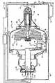
参见图1,示出了X射线管系统20来说明本发明的一些方面。该系统20包括高压电源22、安装在壳体26内的X射线管24、以及热交换器28。该X射线管24通常也称为插入件,该X射线管24稳固地与管支撑件(未示出)以惯用方式相固定并安装在X射线管壳体26内。该壳体26填充有具有高电阻的冷却液,如介电绝缘油。然而,将会理解,其它适当的绝缘和冷却液/介质也可被选用。该油通过供给管线31被泵入由X射线管壳体26限定的室32,该油包围了该X射线管24。泵入的油从X射线管24吸收热量并且通过回流管线34流出壳体26,该回流管线34与设在X射线管壳体26外部的热交换器28连接。该热交换器28包括冷却液泵(未示出)。Referring to Figure 1, an
该X射线管24包括限定了真空室36的真空外壳35。在某些高功率X射线管中,该外壳35可由玻璃结合包括陶瓷和金属在内的其它适当材料制成。例如,阳极壁部分37包括金属,如铜、不锈钢或其它适当金属。中心壁部分39也包括类似的适当金属并且具有X射线透射窗41。该X射线透射窗41可包括铍、钛或别的可供选择的公知适当X射线透明材料。阴极壁部分43包括玻璃或其它适当的陶瓷材料。The
阳极组件38和阴极组件40设在外壳35内。该阳极组件38包括圆靶衬底42,该圆靶衬底42沿着靶42的周缘具有焦点轨迹44。该焦点轨迹44包括钨合金或其它在电子轰击时能产生X射线的适当材料。该阳极组件38还包括由石墨制成的背板46,以帮助冷却靶42。An
该阳极组件38包括用来可旋转地支撑靶42的轴承组件66。该靶42以本领域公知的方式安装在转子杆58上。该转子杆58连接到转子主体64,该转子主体64借助电气定子(未示出)在运行过程中绕着转动轴线转动。该转子主体64容纳为其提供支撑的轴承组件66。The
该阴极组件40处于固定状态并且包括阴极聚焦杯48,该阴极聚焦杯48可操作地设置成相对于聚焦轨迹44间隔开,以便将电子聚焦到聚焦轨迹44上的聚焦斑50。激励安装在阴极聚焦杯48上的阴极丝(未示出)来发射电子54,这些电子54被加速到聚焦斑50以便产生X射线56。The
电源22通过阳极插座72和导体74向阳极组件38提供70kV到100kV的高压,阳极插座72和导体74处于充满冷却液的壳体26内。该插座72和导体74适合于为阳极的运行电压提供电连接。The
阴极组件40用阴极插座75和导体76、78、79适当地连接到电源22,以便向X射线管的阴极组件40提供必要的运行功率,通常为-70kV到-100kv。可选择地,可以将阳极端部接地或接在公共电势上,而只向阴极部件施加适当的高电压,以实现X射线管的正确运行。
如上所述,在X射线管的运行过程中,产生次级和反向散射电子(在下文中统称为“反向散射电子”)并且撞击X射线透射窗以及该窗周围的金属框架。当从靶上被反向散射或从阴极丝直接发射出的电子与该窗或框架有非弹性碰撞时,该电子的动能转化成热量,该热量导致该窗以及周围的框架具有不希望增加的发热。该局部增加的发热使得在框架中固定该窗的接合丧失完整性,并且不利地影响管的性能或寿命。As described above, during operation of the X-ray tube, secondary and backscattered electrons (hereinafter collectively referred to as "backscattered electrons") are generated and strike the X-ray transmission window and the metal frame surrounding the window. When electrons, either backscattered from the target or directly emitted from the cathode filament, collide inelastically with the window or frame, the kinetic energy of the electrons is converted into heat which causes an undesired increase in the window and surrounding frame. fever. This locally increased heating causes the joints securing the window in the frame to lose integrity and adversely affects the performance or life of the tube.
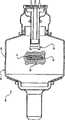
参见图2和图3,按照本发明的方面,该高原子序数(Z)材料的反向散射层90沉积在窗41和框架39的内(真空)表面,该反向散射层90的反向散射系数大于该窗和该框架的反向散射系数。该电子反射系数是入射到表面上的电子在刚一撞击表面就离开该表面的概率。该系数表示为离开该表面的电子相对于入射到该表面的电子的比例。如上所述,该金属框架可以是反向散射系数大约为0.34的铜,或者反向散射系数与铁类似、大约为0.25~0.3的不锈钢。通常,该窗包括铍或钛。铍的反向散射系数为0.04,而钛的反向散射系数为0.25。可以理解,其它适当材料也可用于该窗。2 and 3, according to aspects of the present invention, the
用于反向散射层90的适当高Z材料的两个例子是钨(Z=74)或金(Z=79),钨的反向散射系统大约为0.47,金的反向散射系统大约为0.40。此外,诸如钼(Z=43)和铂(Z=78)的材料对于某些应用也是适用的。该反向散射层90可以用公知的沉积技术来施加,例如静电技术、溅射、火焰喷涂、蒸发、或其它适当技术,该技术在窗41和该窗周围的金属框架39上相对均匀地施加反向散射层90的沉积物。Two examples of suitable high Z materials for
如上文所述那样来施加反向散射层90以便提供均匀的层90,这是因为在X射线56穿出X射线透射窗41的路径上的缺陷会在X射线的图像中产生伪差。此外,过厚的叠片层会不良地衰减透过该窗而指向病人的X射线,并且对图像有不利影响。理想的是,通过在商业上和临床上适当小地增大图像伪差而改善窗41的散射特性,并且将X射线透射过该窗所发生的衰减限制到可接受的程度。The
在铜框架部分上附加适当的钨制反射散射层90可以将从该窗周围的框架区域散射的电子数提高大约13%。这就减少了传递到该窗并转化成热量的入射电子能量。一微米的钨膜厚度是足够来防止60keV的电子穿过该膜并将其能量以热量的形式传递给金属框架。Adding a suitable
当来自于阳极的散射电子的最大穿透深度小于或等于施加在框架上的反射散射层90的膜厚D1以及施加在该窗上的反射散射层的膜厚D2时(图3),电子从相应的层/叠片按照其反向散射系统被反射也就是被再次反向散射。在电子的最大穿透深度大于D1和D2情况下,反向散射系数近似为衬底材料即框架或窗的反向散射系数。When the maximum penetration depth of the scattered electrons from the anode is less than or equal to the film thicknessD1 of the
在本发明中,相应的反向散射层90的厚度足以降低在特定能量范围内完全穿透到该框架或窗的电子数量。这样,窗区域周围的反向散射系数以及对于该窗的反向散射系数是相应层的反向散射系数,而不是该框架/窗的相应系数。这些被再次反向散射的电子没有被吸收在该窗/框架内,而且降低了局部的窗/框架发热。In the present invention, the thickness of the
然而,该反向散射叠片92的厚度D2还被选择成能满足X射线衰减的较低阈值。更具体地说,希望将X射线窗41和反向散射层90引起的X射线束衰减限制到与2.5mm厚的铝类似于的衰减值。这种限制对应于铍窗上大约9.5微米厚的钨,以及钛窗上大约8.0微米厚的钨,这将在下文中描述。However, the thicknessD2 of the
图4示出了在两种X射线透射窗材料亦即铍和钛的情况下X射线束透射百分比降低的图形表示,该透射百分比是钨涂层厚度的函数。对于该窗和反向散射材料的其它适当尺寸和材料的组合来说,也存在类似的透射衰减关系。该图形表示的阈值用线100示出,该线100表示入射到该窗的X射线有88.5%的透射率,而且该线100对应于2.5mm的铝厚度。在该表示中,线102表示对于带有钨反向散射层的铍窗的X射线透射率的变化。线104类似地表示了带有钨反向散射层的钛窗。线106表示只对于钨反向散射材料来说X射线透射率的变化。Figure 4 shows a graphical representation of the reduction in percent X-ray beam transmission as a function of tungsten coating thickness for two X-ray transparent window materials, namely Beryllium and Titanium. Similar transmission attenuation relationships exist for other suitable size and material combinations of the window and backscattering material. The threshold of the graphical representation is shown by
对于图4中的表示,铍窗的窗厚度为0.102cm、在93Kev处的衰减系数为1357cm2/gm,其标称密度为1.845gm/cm3。对于钛窗,窗厚度为0.030cm,在93Kev处的衰减系数为0.3006cm2/gm,其标称密度为4.53gm/cm3。钨反向散射材料在93Kev处的衰减系数为5.2412cm2/gm,其标称密度为19.3gm/cm3。X射线透射率线104说明,8.0微米厚的钨层与钛窗一起满足了线100所示的透射率下限。X射线透射率线102说明,9.5微米厚的钨层与铍窗一起满足了线100所示的透射率下限。可以理解,按照本发明的原理可以使用不同厚度的X射线透射窗、反向散射层以及透射率的下降极限,而且本发明不限于上文列举的具体例子。For the representation in Figure 4, the beryllium window has a window thickness of 0.102 cm, an attenuation coefficient of 1357 cm2 /gm at 93 KeV, and a nominal density of 1.845 gm/cm3 . For a titanium window, the window thickness is 0.030 cm, the attenuation coefficient at 93 Kev is 0.3006 cm2 /gm, and its nominal density is 4.53 gm/cm3 . The attenuation coefficient of tungsten backscattering material at 93Kev is 5.2412cm2 /gm, and its nominal density is 19.3gm/cm3 .
尽管上文仅对于一个所示实施例来描述本发明的一个特定特征,但是这些特征可以与其它实施例的一个或多个其它特征相组合,这对于任何给定的特定应用来说是需要的且有益的。Although one particular feature of the invention has been described above with respect to only one illustrated embodiment, those features may be combined with one or more other features of other embodiments, as desired for any given particular application and beneficial.
通过本发明的上述说明,本领域的技术人员会认识到改进、变化和变型。所附的权利要求书要覆盖这些本领域技术范围内的改进、变化和变型。From the above description of the invention, those skilled in the art will perceive improvements, changes and modifications. The appended claims are intended to cover such improvements, changes and modifications within the skill of the art.
Claims (7)
Applications Claiming Priority (2)
| Application Number | Priority Date | Filing Date | Title |
|---|---|---|---|
| US47473703P | 2003-05-30 | 2003-05-30 | |
| US60/474,737 | 2003-05-30 |
Publications (2)
| Publication Number | Publication Date |
|---|---|
| CN1799117A CN1799117A (en) | 2006-07-05 |
| CN100555549Ctrue CN100555549C (en) | 2009-10-28 |
Family
ID=33490729
Family Applications (1)
| Application Number | Title | Priority Date | Filing Date |
|---|---|---|---|
| CNB2004800150450AExpired - Fee RelatedCN100555549C (en) | 2003-05-30 | 2004-05-12 | Enhanced Electron Backscattering in X-ray Tubes |
Country Status (5)
| Country | Link |
|---|---|
| US (1) | US7260181B2 (en) |
| EP (1) | EP1634315A2 (en) |
| JP (1) | JP2007504634A (en) |
| CN (1) | CN100555549C (en) |
| WO (1) | WO2004107384A2 (en) |
Families Citing this family (12)
| Publication number | Priority date | Publication date | Assignee | Title |
|---|---|---|---|---|
| DE102004035090A1 (en)* | 2004-07-20 | 2006-02-16 | Sirona Dental Systems Gmbh | Compensation part and method for the measurement of dental restorations |
| JP4644508B2 (en)* | 2005-03-30 | 2011-03-02 | 東芝電子管デバイス株式会社 | X-ray tube |
| US7688949B2 (en)* | 2007-09-28 | 2010-03-30 | Varian Medical Systems, Inc. | X-ray tube cooling system |
| US7616736B2 (en)* | 2007-09-28 | 2009-11-10 | Varian Medical Systems, Inc. | Liquid cooled window assembly in an x-ray tube |
| US7796737B2 (en)* | 2008-05-07 | 2010-09-14 | General Electric Company | Apparatus for reducing KV-dependent artifacts in an imaging system and method of making same |
| DE102008038569A1 (en) | 2008-08-20 | 2010-02-25 | Siemens Aktiengesellschaft | X-ray tube |
| DE102009008046A1 (en)* | 2009-02-09 | 2010-08-19 | Siemens Aktiengesellschaft | An X-ray tube having a backscattered electron capture device and methods of operating such an X-ray tube |
| DE102010040407A1 (en) | 2010-09-08 | 2012-03-08 | Siemens Aktiengesellschaft | X-ray tube, has anode partially comprising surface coatings provided outside stopping area of focal spot, where surface coatings are made of material with nuclear charge number less than nuclear charge number of material of anode |
| DE102015219029B4 (en)* | 2015-10-01 | 2023-11-02 | Siemens Healthcare Gmbh | Rotating anode, X-ray tube and arrangement with an X-ray tube and method for producing a rotor of a rotating anode |
| CN106128927A (en)* | 2016-08-10 | 2016-11-16 | 昆山国力真空电器有限公司 | Sigmatron pipe |
| WO2019027072A1 (en)* | 2017-08-04 | 2019-02-07 | 주식회사 엑스엘 | Portable x-ray tube |
| CN115841935B (en)* | 2023-02-20 | 2023-05-12 | 安徽科昂新材料科技有限公司 | An X-ray source device |
Citations (4)
| Publication number | Priority date | Publication date | Assignee | Title |
|---|---|---|---|---|
| US4731804A (en)* | 1984-12-31 | 1988-03-15 | North American Philips Corporation | Window configuration of an X-ray tube |
| CN1060738A (en)* | 1990-10-19 | 1992-04-29 | 株式会社东芝 | Rotating Anode X-ray Tube |
| US6118852A (en)* | 1998-07-02 | 2000-09-12 | General Electric Company | Aluminum x-ray transmissive window for an x-ray tube vacuum vessel |
| DE10023356A1 (en)* | 2000-05-12 | 2001-11-29 | Siemens Ag | Electron tube has higher thermal absorption coefficient coating with layer of tantalum applied to metal material bounding on vacuum and layer of carbon applied to tantalum |
Family Cites Families (14)
| Publication number | Priority date | Publication date | Assignee | Title |
|---|---|---|---|---|
| US4339687A (en) | 1980-05-29 | 1982-07-13 | General Electric Company | Shadow mask having a layer of high atomic number material on gun side |
| DE3107949A1 (en) | 1981-03-02 | 1982-09-16 | Siemens AG, 1000 Berlin und 8000 München | X-RAY TUBES |
| US5206895A (en) | 1990-08-24 | 1993-04-27 | Michael Danos | X-ray tube |
| JPH04315752A (en) | 1990-11-21 | 1992-11-06 | Varian Assoc Inc | High-output rotary-anode x-ray tube |
| JPH07230892A (en) | 1993-12-20 | 1995-08-29 | Toshiba Corp | X-ray tube for fluorescence analysis and manufacturing method thereof |
| US5511104A (en) | 1994-03-11 | 1996-04-23 | Siemens Aktiengesellschaft | X-ray tube |
| JPH08129980A (en) | 1994-10-28 | 1996-05-21 | Shimadzu Corp | Anode for X-ray tube |
| DE19542438C1 (en) | 1995-11-14 | 1996-11-28 | Siemens Ag | X=ray tube with vacuum housing having cathode and anode |
| DE19627025C2 (en) | 1996-07-04 | 1998-05-20 | Siemens Ag | X-ray tube |
| US6005918A (en) | 1997-12-19 | 1999-12-21 | Picker International, Inc. | X-ray tube window heat shield |
| US5987097A (en) | 1997-12-23 | 1999-11-16 | General Electric Company | X-ray tube having reduced window heating |
| US5995585A (en) | 1998-02-17 | 1999-11-30 | General Electric Company | X-ray tube having electron collector |
| JP2000306533A (en)* | 1999-02-19 | 2000-11-02 | Toshiba Corp | Transmission radiation type X-ray tube and method of manufacturing the same |
| AU2001296611A1 (en) | 2000-10-23 | 2002-05-06 | Varian Medical Systems, Inc. | X-ray tube and method of manufacture |
- 2004
- 2004-05-12CNCNB2004800150450Apatent/CN100555549C/ennot_activeExpired - Fee Related
- 2004-05-12EPEP04732367Apatent/EP1634315A2/ennot_activeWithdrawn
- 2004-05-12USUS10/558,767patent/US7260181B2/ennot_activeExpired - Fee Related
- 2004-05-12JPJP2006530691Apatent/JP2007504634A/ennot_activeWithdrawn
- 2004-05-12WOPCT/IB2004/001725patent/WO2004107384A2/enactiveApplication Filing
Patent Citations (4)
| Publication number | Priority date | Publication date | Assignee | Title |
|---|---|---|---|---|
| US4731804A (en)* | 1984-12-31 | 1988-03-15 | North American Philips Corporation | Window configuration of an X-ray tube |
| CN1060738A (en)* | 1990-10-19 | 1992-04-29 | 株式会社东芝 | Rotating Anode X-ray Tube |
| US6118852A (en)* | 1998-07-02 | 2000-09-12 | General Electric Company | Aluminum x-ray transmissive window for an x-ray tube vacuum vessel |
| DE10023356A1 (en)* | 2000-05-12 | 2001-11-29 | Siemens Ag | Electron tube has higher thermal absorption coefficient coating with layer of tantalum applied to metal material bounding on vacuum and layer of carbon applied to tantalum |
Also Published As
| Publication number | Publication date |
|---|---|
| US7260181B2 (en) | 2007-08-21 |
| JP2007504634A (en) | 2007-03-01 |
| US20070025517A1 (en) | 2007-02-01 |
| WO2004107384A3 (en) | 2005-07-07 |
| CN1799117A (en) | 2006-07-05 |
| EP1634315A2 (en) | 2006-03-15 |
| WO2004107384A2 (en) | 2004-12-09 |
Similar Documents
| Publication | Publication Date | Title |
|---|---|---|
| US6005918A (en) | X-ray tube window heat shield | |
| US7664230B2 (en) | X-ray tubes | |
| US6215852B1 (en) | Thermal energy storage and transfer assembly | |
| US7978824B2 (en) | X-ray tube having transmission anode | |
| US20140211919A1 (en) | X-ray generator and x-ray imaging apparatus | |
| CN100555549C (en) | Enhanced Electron Backscattering in X-ray Tubes | |
| JP2013020791A (en) | Radiation generating device and radiography device using it | |
| EP0009946A1 (en) | X-ray tube | |
| EP0491471A2 (en) | High power x-ray tube | |
| JP2010262784A (en) | X-ray tube and X-ray tube device | |
| CN111430204A (en) | X-ray tube and medical imaging apparatus | |
| EP2856492A1 (en) | Cooled stationary anode for an x-ray tube | |
| US7058160B2 (en) | Shield structure for x-ray device | |
| US7145988B2 (en) | Sealed electron beam source | |
| CN116403877A (en) | X-ray tube capable of suppressing secondary electron emission | |
| CN110942968B (en) | X-ray tube and medical imaging device having the same | |
| CN210628240U (en) | X-ray tube and medical imaging apparatus having the same | |
| US6359968B1 (en) | X-ray tube capable of generating and focusing beam on a target | |
| US6044129A (en) | Gas overload and metalization prevention for x-ray tubes | |
| EP3800656A1 (en) | Scattered electron capturing for rotating anode x-ray tubes | |
| JPH04262348A (en) | Structure of fixed anode of x-ray tube | |
| JP2002352756A (en) | Rotating anode type X-ray tube device | |
| EP0768699A1 (en) | X-ray tube and barrier means therefor | |
| CN117690767A (en) | A ray tube that improves the conversion efficiency of monoenergetic X-rays | |
| CN100573799C (en) | The X-ray source of generating monochromatic x-rays |
Legal Events
| Date | Code | Title | Description |
|---|---|---|---|
| C06 | Publication | ||
| PB01 | Publication | ||
| C10 | Entry into substantive examination | ||
| SE01 | Entry into force of request for substantive examination | ||
| C14 | Grant of patent or utility model | ||
| GR01 | Patent grant | ||
| C17 | Cessation of patent right | ||
| CF01 | Termination of patent right due to non-payment of annual fee | Granted publication date:20091028 Termination date:20100512 |