CN100554785C - Be used for combustion tube and method that the air of gas turbine is mixed - Google Patents
Be used for combustion tube and method that the air of gas turbine is mixedDownload PDFInfo
- Publication number
- CN100554785C CN100554785CCNB2005100785224ACN200510078522ACN100554785CCN 100554785 CCN100554785 CCN 100554785CCN B2005100785224 ACNB2005100785224 ACN B2005100785224ACN 200510078522 ACN200510078522 ACN 200510078522ACN 100554785 CCN100554785 CCN 100554785C
- Authority
- CN
- China
- Prior art keywords
- fuel
- centerbody
- air
- burner
- distribution ring
- Prior art date
- Legal status (The legal status is an assumption and is not a legal conclusion. Google has not performed a legal analysis and makes no representation as to the accuracy of the status listed.)
- Expired - Fee Related
Links
- 238000002485combustion reactionMethods0.000titleclaimsdescription35
- 238000000034methodMethods0.000titledescription7
- 239000000446fuelSubstances0.000claimsdescription110
- 238000005452bendingMethods0.000claims1
- 230000014759maintenance of locationEffects0.000claims1
- 239000007789gasSubstances0.000description21
- 238000006243chemical reactionMethods0.000description16
- 230000002093peripheral effectEffects0.000description14
- 239000000203mixtureSubstances0.000description13
- 238000002347injectionMethods0.000description9
- 239000007924injectionSubstances0.000description9
- IJGRMHOSHXDMSA-UHFFFAOYSA-NAtomic nitrogenChemical compoundN#NIJGRMHOSHXDMSA-UHFFFAOYSA-N0.000description5
- 229930195733hydrocarbonNatural products0.000description5
- 150000002430hydrocarbonsChemical class0.000description5
- 238000000926separation methodMethods0.000description5
- UGFAIRIUMAVXCW-UHFFFAOYSA-NCarbon monoxideChemical compound[O+]#[C-]UGFAIRIUMAVXCW-UHFFFAOYSA-N0.000description4
- 229910002091carbon monoxideInorganic materials0.000description4
- 230000009977dual effectEffects0.000description4
- 238000010586diagramMethods0.000description3
- 238000005553drillingMethods0.000description3
- MWUXSHHQAYIFBG-UHFFFAOYSA-Nnitrogen oxideInorganic materialsO=[N]MWUXSHHQAYIFBG-UHFFFAOYSA-N0.000description3
- 238000013021overheatingMethods0.000description3
- 239000004215Carbon black (E152)Substances0.000description2
- 238000010276constructionMethods0.000description2
- 238000009792diffusion processMethods0.000description2
- 239000007788liquidSubstances0.000description2
- 229910052757nitrogenInorganic materials0.000description2
- 230000008569processEffects0.000description2
- 230000009467reductionEffects0.000description2
- 230000007704transitionEffects0.000description2
- 238000003491arrayMethods0.000description1
- 230000000712assemblyEffects0.000description1
- 238000000429assemblyMethods0.000description1
- 230000015572biosynthetic processEffects0.000description1
- 238000005266castingMethods0.000description1
- 239000000919ceramicSubstances0.000description1
- 239000000567combustion gasSubstances0.000description1
- 230000001419dependent effectEffects0.000description1
- 238000013461designMethods0.000description1
- 239000003085diluting agentSubstances0.000description1
- 230000000694effectsEffects0.000description1
- 238000005516engineering processMethods0.000description1
- 230000001747exhibiting effectEffects0.000description1
- 239000012530fluidSubstances0.000description1
- 239000008240homogeneous mixtureSubstances0.000description1
- 238000005495investment castingMethods0.000description1
- 238000012986modificationMethods0.000description1
- 230000004048modificationEffects0.000description1
- 230000003647oxidationEffects0.000description1
- 238000007254oxidation reactionMethods0.000description1
- 230000008929regenerationEffects0.000description1
- 238000011069regeneration methodMethods0.000description1
- 238000011160researchMethods0.000description1
- 230000002269spontaneous effectEffects0.000description1
- 230000000087stabilizing effectEffects0.000description1
- 230000035882stressEffects0.000description1
- 230000008646thermal stressEffects0.000description1
- 238000011144upstream manufacturingMethods0.000description1
- XLYOFNOQVPJJNP-UHFFFAOYSA-NwaterSubstancesOXLYOFNOQVPJJNP-UHFFFAOYSA-N0.000description1
Images


Classifications
- F—MECHANICAL ENGINEERING; LIGHTING; HEATING; WEAPONS; BLASTING
- F23—COMBUSTION APPARATUS; COMBUSTION PROCESSES
- F23R—GENERATING COMBUSTION PRODUCTS OF HIGH PRESSURE OR HIGH VELOCITY, e.g. GAS-TURBINE COMBUSTION CHAMBERS
- F23R3/00—Continuous combustion chambers using liquid or gaseous fuel
- F23R3/02—Continuous combustion chambers using liquid or gaseous fuel characterised by the air-flow or gas-flow configuration
- F23R3/04—Air inlet arrangements
- F23R3/10—Air inlet arrangements for primary air
- F23R3/12—Air inlet arrangements for primary air inducing a vortex
- F23R3/14—Air inlet arrangements for primary air inducing a vortex by using swirl vanes
- F—MECHANICAL ENGINEERING; LIGHTING; HEATING; WEAPONS; BLASTING
- F23—COMBUSTION APPARATUS; COMBUSTION PROCESSES
- F23R—GENERATING COMBUSTION PRODUCTS OF HIGH PRESSURE OR HIGH VELOCITY, e.g. GAS-TURBINE COMBUSTION CHAMBERS
- F23R3/00—Continuous combustion chambers using liquid or gaseous fuel
- F23R3/28—Continuous combustion chambers using liquid or gaseous fuel characterised by the fuel supply
- F23R3/286—Continuous combustion chambers using liquid or gaseous fuel characterised by the fuel supply having fuel-air premixing devices
- F—MECHANICAL ENGINEERING; LIGHTING; HEATING; WEAPONS; BLASTING
- F23—COMBUSTION APPARATUS; COMBUSTION PROCESSES
- F23C—METHODS OR APPARATUS FOR COMBUSTION USING FLUID FUEL OR SOLID FUEL SUSPENDED IN A CARRIER GAS OR AIR
- F23C2900/00—Special features of, or arrangements for combustion apparatus using fluid fuels or solid fuels suspended in air; Combustion processes therefor
- F23C2900/07001—Air swirling vanes incorporating fuel injectors
Landscapes
- Engineering & Computer Science (AREA)
- Chemical & Material Sciences (AREA)
- Combustion & Propulsion (AREA)
- Mechanical Engineering (AREA)
- General Engineering & Computer Science (AREA)
Abstract
Translated fromChinese
Description
Translated fromChinese技术领域technical field
本发明涉及重型工业燃气轮机,更具体地说涉及用于燃气轮机的燃烧器,其包括燃料/空气预混器以及用于稳定燃气轮机燃烧室中的已预混燃烧气体的结构。The present invention relates to heavy industrial gas turbines, and more particularly to combustors for gas turbines including fuel/air premixers and structures for stabilizing premixed combustion gases in the gas turbine combustor.
背景技术Background technique
燃气轮机的制造商经常性地专注于用来生产新型燃气轮机的研究和工程项目,这种燃气轮机能够高效率地运转,同时不会产生不合要求的空气污染排放物。燃烧传统烃类燃料的燃气轮机通常产生的主要空气污染排放物是氮的氧化物、一氧化碳以及未燃烃。在本领域中众所周知,喷气发动机中的分子氮的氧化在很大程度上取决于燃烧系统反应区中的最高热气温度。形成氮的氧化物(NOX)的化学反应的速度是温度的指数函数。如果将燃烧室的热气温度控制在足够低的水平,那么就不会产生热的NOX。Manufacturers of gas turbines frequently focus on research and engineering programs to produce new types of gas turbines that can operate at high efficiency without producing undesired air-polluting emissions. The main air polluting emissions typically produced by gas turbines burning conventional hydrocarbon fuels are oxides of nitrogen, carbon monoxide, and unburned hydrocarbons. It is well known in the art that the oxidation of molecular nitrogen in jet engines is largely dependent on the maximum hot gas temperature in the reaction zone of the combustion system. The rate of the chemical reaction to form oxides of nitrogen (NOx ) is an exponential function of temperature. If the temperature of the hot gas in the combustion chamber is controlled at a sufficiently low level, no thermalNOx is produced.
将燃烧室反应区的温度控制在低于会形成热NOX的温度水平的一种优选方法是,在燃烧之前将燃料和空气预混成贫混合气。存在于贫预混式燃烧室的反应区中的过量空气的热质量吸收热量,并将燃烧产物的温升降低到不会形成热NOX的水平。A preferred method of controlling the temperature of the reaction zone of the combustor below a level at which thermalNOx is formed is to premix the fuel and air to a lean mixture prior to combustion. The thermal mass of the excess air present in the reaction zone of the lean premixed combustor absorbs heat and reduces the temperature rise of the combustion products to a level where thermalNOx is not formed.
若干问题与干燥低排放物的燃烧室相关,这种燃烧室在燃料和空气的贫预混条件下工作,其中燃料和空气的可燃混合气存在于燃烧室中的位于燃烧室反应区之外的预混部分中。由于逆燃或自燃的原因,在预混部分中可能会发生燃烧,当火焰从燃烧室反应区扩散到预混部分时会发生逆燃,当燃料/空气混合气在预混部分中的滞留时间和温度足以使得在没有点火器的条件下也能启动燃烧时就会发生自燃。在预混部分中产生燃烧的结果是排放性能降低和/或预混部分过热和受损,而预混部分通常未被设计成能承受燃烧的热量。因此,要解决的问题是防止会导致在预混器中产生燃烧的逆燃或自燃。Several problems are associated with dry low emission combustors operating under lean premixed conditions of fuel and air, where a combustible mixture of fuel and air exists in the combustor outside the reaction zone of the combustor. in the premix section. Combustion may occur in the premix section due to flashback or autoignition, which occurs when the flame spreads from the combustion chamber reaction zone to the premix section, when the residence time of the fuel/air mixture in the premix section Spontaneous combustion occurs when the temperature is sufficient to initiate combustion without an igniter. The result of combustion in the premix section is reduced emissions performance and/or overheating and damage to the premix section, which is generally not designed to withstand the heat of combustion. Therefore, the problem to be solved is to prevent flashback or auto-ignition which would lead to combustion in the premixer.
另外,离开预混器并进入燃烧室反应区中的燃料和空气混合气必须是非常均匀的,以达到所需的排放性能。如果在流场中存在其中燃料/空气混合气浓度显著高于平均水平的区域,那么这些区域中的燃烧产物将达到比平均水平更高的温度,并且会形成热NOX。这可能导致无法根据温度和滞留时间的组合来满足NOX排放的目标。如果在流场中存在其中燃料/空气混合气浓度显著低于平均水平的区域,那么就可能发生熄火,导致不能将烃和/或一氧化碳氧化至平衡水平。这可能导致无法满足一氧化碳(CO)和/或未燃烃(UHC)的排放目标。因此,需要解决的另一问题是产生离开预混器的足够均匀以满足排放性能目标的燃料/空气混合气的浓度分布。Additionally, the fuel and air mixture leaving the premixer and entering the reaction zone of the combustor must be very homogeneous to achieve the desired emissions performance. If there are regions in the flow field where the fuel/air mixture concentration is significantly higher than average, the combustion products in these regions will reach higher than average temperatures and thermalNOx will form. This can lead to failure to meetNOx emission targets based on the combination of temperature and residence time. Flameout may occur if there are regions in the flow field where the fuel/air mixture concentration is significantly lower than average, resulting in failure to oxidize hydrocarbons and/or carbon monoxide to equilibrium levels. This can lead to failure to meet emissions targets for carbon monoxide (CO) and/or unburned hydrocarbons (UHC). Therefore, another problem that needs to be addressed is to produce a concentration profile of the fuel/air mixture exiting the premixer that is uniform enough to meet emissions performance targets.
另外,为了满足在许多应用中施加于燃气轮机上的排放性能目标,需要将燃料/空气混合气的浓度降低到接近大多数烃类燃料的贫燃极限的水平。这将导致火焰扩散速度和排放物的降低。结果,贫预混式燃烧室将变得比大多数传统的扩散火焰式燃烧室更不稳定,并经常导致燃烧所产生的较高水平的动态压力波动(动态特性)。动态特性可能具有负面影响,例如因磨损或疲劳、逆燃或爆裂而引起燃烧室和涡轮硬件的损坏。因此,需要解决的另一问题是将燃烧的动态特性控制在可接受的低水平。Additionally, in order to meet the emission performance targets imposed on gas turbines in many applications, the concentration of the fuel/air mixture needs to be reduced to levels approaching the lean burn limit of most hydrocarbon fuels. This will result in a reduction in flame spread rate and emissions. As a result, lean premixed combustors will become less stable than most conventional diffusion flame combustors and often result in higher levels of dynamic pressure fluctuations (dynamic characteristics) resulting from combustion. Dynamic characteristics can have negative effects such as damage to combustor and turbine hardware due to wear or fatigue, flashback or blowout. Therefore, another problem to be solved is to control the dynamics of the combustion to an acceptably low level.
用于减少排放物的贫预混式燃料喷射器普遍用于整个行业中,其已经被简化应用于重型工业燃气轮机中超过二十年。在美国专利No.5259184中介绍了这种装置的一个代表性示例,该专利公开通过引用结合于本文中。这种装置已经在减少燃气轮机的废气排放物的领域中取得了重大进展。在不使用喷射稀释剂如蒸气或水的条件下,相对于现有技术的扩散火焰式燃烧器而言,氮的氧化物NOX的排放已降低了一个数量级或更多。Lean premixed fuel injectors for reducing emissions are commonly used throughout the industry and have been simplified for use in heavy industrial gas turbines for over two decades. A representative example of such a device is described in US Patent No. 5,259,184, the disclosure of which is incorporated herein by reference. Such devices have made significant progress in the field of reducing exhaust emissions from gas turbines. Nitrogen oxidesNOx emissions have been reduced by an order of magnitude or more relative to prior art diffusion flame burners without the use of injected diluents such as steam or water.
然而,如上所述,在排放性能方面的这些收获是在冒有会引起若干问题的风险下取得的。特别是,由于过热的原因,被保持在装置的预混部分中的逆燃和火焰会导致排放性能降低和/或硬件破坏。另外,燃烧所产生的动态压力波动的水平增加,导致燃烧系统的部件和/或燃气轮机的其它部件的使用寿命因磨损或高周疲劳失效而缩短。此外,为了避免会导致高水平的动态压力波动、逆燃或爆裂的状况,燃气轮机的操作复杂性增加,和/或必须对燃气轮机设定操作限制。However, as noted above, these gains in emissions performance have been made at the risk of causing several problems. In particular, flashback and flames that are held in the premix portion of the device due to overheating can lead to reduced emissions performance and/or hardware damage. Additionally, the level of dynamic pressure fluctuations generated by combustion increases, resulting in shortened service life of components of the combustion system and/or other components of the gas turbine due to wear or high cycle fatigue failure. Furthermore, to avoid conditions that would result in high levels of dynamic pressure fluctuations, flashback or blowout, the operational complexity of the gas turbine increases and/or operating limits must be placed on the gas turbine.
除了这些问题之外,传统的贫预混式燃烧室无法在燃料和空气非常均匀地预混的条件下实现最大可能地减少排放物。In addition to these problems, conventional lean premixed combustors cannot achieve the greatest possible reduction in emissions under conditions where the fuel and air are premixed very uniformly.
双环形对转式旋流器(DACRS)型燃料喷射器的旋流器是已知的,其因较高的流体剪切和湍流而具有非常良好的混合特性,在美国专利No.5165241、No.5251447、No.5351477、No.5590529、No.5638682和No.5680766中介绍了其代表性的示例,这些专利的公开内容通过引用结合于本文中。参见图1中的示意性图示,DACRS型燃烧器10由收敛型中心体12和对转式叶片组14构成,叶片组14限定了相对于中心体轴线20的径向内通道16和径向外通道18,这些同轴通道均具有旋流叶片。这种喷嘴结构由外径支撑杆22来支撑,其包含了用于将燃料输送到外通道18的叶片中的燃料歧管24。Swirlers of double annular counter-rotating swirler (DACRS) type fuel injectors are known, which have very good mixing characteristics due to high fluid shear and turbulence, in US Patent No. 5165241, No. Representative examples thereof are described in No. 5,251,447, No. 5,351,477, No. 5,590,529, No. 5,638,682, and No. 5,680,766, the disclosures of which are incorporated herein by reference. Referring to the schematic illustration in FIG. 1 , a DACRS-
虽然已知DACRS型燃料喷射器的旋流器具有非常良好的混合特性,但是这些旋流器并不能在中心线处产生强大的循环流,因此经常需要另外地喷射未预混燃料,以便使火焰完全稳定。这种未预混燃料将NOX的排放量增大到高于如同燃料和空气完全混合时可能达到的水平。Although the swirlers of DACRS-type fuel injectors are known to have very good mixing characteristics, these swirlers do not produce a strong recirculation flow at the centerline, often requiring an additional injection of unpremixed fuel in order to keep the flame completely stable. Such unpremixed fuel increasesNOx emissions above what would be possible if the fuel and air were thoroughly mixed.
旋流喷嘴(swozzle)型燃烧器采用了沿着燃烧器的中心线延伸的圆柱形中心体,在美国专利No.6438961中介绍了该燃烧器的代表性例子,其公开内容通过引用结合于本文中。这种中心体的末端设有非流线形体,从而在其尾流处形成了使火焰稳定的强烈的再循环区域。这类燃烧器的结构是已知的,其具有良好的固有火焰稳定性。A representative example of a swozzle type burner employing a cylindrical centerbody extending along the centerline of the burner is described in U.S. Patent No. 6,438,961, the disclosure of which is incorporated herein by reference middle. This central body is terminated with a bluff body creating an intense recirculation zone in its wake that stabilizes the flame. The construction of such burners is known and has good inherent flame stability.
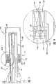
参看图2,图中示意性地显示了旋流喷嘴型燃烧器的一个例子。空气在标号40处从高压气室进入到燃烧器42中,高压气室包围了该组件,但伸入到燃烧室反应区中的排气端44除外。Referring to Fig. 2, an example of a swozzle type burner is schematically shown. Air enters the
在穿过入口40之后,空气进入到旋流器或“旋流喷嘴”组件50中。旋流喷嘴组件包括毂部52(如中心体)以及由一系列翼型形状的导向叶片56所连接的护罩54,其中叶片56将涡流施加到经过预混器的燃烧空气中。各导向叶片56包括穿过翼型芯部的气体燃料供给通道。这些燃料通道将气体燃料分布到穿过翼型壁的气体燃料注入孔(未示出)中。气体燃料经由为导向叶片通道58供料的入口和环形通道60而进入到旋流喷嘴组件中。气体燃料在旋流喷嘴组件62中开始与燃烧空气混合,并且在由中心体延伸部分64和旋流喷嘴护罩延伸部分66所形成的环形通道中完成燃料/空气的混合。在离开环形通道之后,燃料/空气混合气进入燃烧室反应区,在这里进行燃烧。After passing through
DACRS型和旋流喷嘴型燃烧器都是沿用已久的燃烧器技术。但是这并不是说这些燃烧器不能得到提高。的确,如上所述,DACRS型燃烧器通常并不能提供良好的预混火焰稳定性。另一方面,旋流喷嘴型燃烧器通常无法实现燃料和空气的完全均匀的预混。Both the DACRS type and the swozzle type burner are well established burner technologies. But that's not to say these burners can't be improved. Indeed, as noted above, DACRS type burners generally do not provide good premixed flame stability. On the other hand, swozzle-type burners generally cannot achieve a completely homogeneous premixing of fuel and air.
发明内容Contents of the invention
本发明提供了一种燃烧器概念的独特组合,其包括有展示出极佳混合特性的双重对转式轴流旋流器,以及可提供良好火焰稳定性的圆柱形的非流线型中心体。The present invention provides a unique combination of burner concepts including dual counter-rotating axial swirlers exhibiting excellent mixing characteristics, and a cylindrical bluff centerbody that provides good flame stability.
这样,本发明可体现为用于工业燃气轮机的燃烧系统中的燃烧器,该燃烧器包括:外周壁;同轴地设置在所述外周壁中的燃烧器中心体;包括空气入口、至少一个燃料入口和分配环的燃料/空气预混器,所述分配环与中心体一起限定了相对于中心体轴线的第一径向内通道,并与外周壁一起限定了第二径向外通道,第一径向内通道和第二径向外通道均具有可对穿过预混器的燃烧空气施加涡流的气流导向叶片,所述叶片分别与所述中心体和所述分配环相连,以及与所述分配环和所述外周壁相连;以及气体燃料的流动通道,其形成在所述中心体内并至少部分地沿着中心体周向地延伸,从而将气体燃料引导至所述燃料/空气预混器中。Thus, the present invention may be embodied as a combustor for use in a combustion system of an industrial gas turbine, the combustor comprising: a peripheral wall; a burner center body coaxially disposed in said peripheral wall; comprising an air inlet, at least one fuel Fuel/air premixer of inlet and distribution ring, said distribution ring together with the central body defines a first radially inner passage with respect to the central body axis and with the peripheral wall defines a second radially outer passage, No. A radially inner channel and a second radially outer channel each have flow guide vanes for imparting swirl flow to combustion air passing through the premixer, said vanes being connected to said central body and said distribution ring respectively, and to said the distribution ring is connected to the peripheral wall; and gaseous fuel flow passages are formed in the center body and extend at least partially circumferentially along the center body to direct the gaseous fuel to the fuel/air premix device.
本发明也可体现为用于工业燃气轮机的燃烧系统中的燃烧器,该燃烧器包括:外周壁;同轴地设置在所述外周壁中的燃烧器中心体;包括空气入口、至少一个燃料入口和分配环的燃料/空气预混器,所述分配环与中心体一起限定了相对于中心体轴线的第一径向内通道,并与外周壁一起限定了第二径向外通道,第一径向内通道和第二径向外通道均具有可对穿过预混器的燃烧空气施加涡流的气流导向叶片,所述叶片分别与所述中心体和所述分配环相连,以及与所述分配环和所述外周壁相连;以及形成在所述外周壁和所述中心体之间并位于导向叶片下游的环形混合通道,所述外周壁通常平行于所述中心体、并平行于所述中心体的所述轴线而延伸,使得所述混合通道具有沿着中心体的长度基本上恒定的内径和外径。The present invention may also be embodied as a burner for use in a combustion system of an industrial gas turbine, the burner comprising: a peripheral wall; a burner center body coaxially disposed in said peripheral wall; comprising an air inlet, at least one fuel inlet and a fuel/air premixer of a distribution ring which, together with the central body, defines a first radially inner passage with respect to the axis of the central body and, together with the peripheral wall, defines a second radially outer passage, the first Both the radially inner channel and the second radially outer channel have flow guide vanes for imparting swirl flow to the combustion air passing through the premixer, said vanes being connected to said central body and said distribution ring, respectively, and to said a distribution ring connected to the peripheral wall; and an annular mixing channel formed between the peripheral wall and the central body and downstream of the guide vanes, the peripheral wall being generally parallel to the central body and parallel to the The axis of the central body extends such that the mixing channel has an inner diameter and an outer diameter that are substantially constant along the length of the central body.
本发明还可体现为在用于燃气轮机燃烧系统的燃烧器中使燃料和空气预混的方法,该燃烧器包括:外周壁;同轴地设置在所述外周壁中的燃烧器中心体;包括空气入口、至少一个燃料入口和分配环的燃料/空气预混器,所述分配环与中心体一起限定了相对于中心体轴线的第一径向内通道,并与外周壁一起限定了第二径向外通道,第一和第二通道均具有可对穿过预混器的燃烧空气施加涡流的气流导向叶片,所述叶片分别与所述中心体和所述分配环相连,以及与所述分配环和所述外周壁相连,至少一些所述叶片包括有内部燃料流动通道,燃料入口将燃料引导至所述内部燃料流动通道中;以及气体燃料的流动通道,其形成在所述中心体内并至少部分地沿着中心体周向地延伸,从而将气体燃料引导至所述燃料/空气预混器中;该方法包括:(a)控制燃料入口上游的进气的径向和周向分布;(b)使所述进气流入所述旋流器组件的所述第一和第二通道中;(c)利用所述导向叶片对所述进气施加涡流;以及(d)在所述导向叶片的下游使燃料和空气混合成均匀的混合气,以便喷入到燃烧器的燃烧室反应区中。The present invention may also be embodied in a method of premixing fuel and air in a combustor for a gas turbine combustion system, the combustor comprising: a peripheral wall; a burner centerbody coaxially disposed within the peripheral wall; comprising A fuel/air premixer of an air inlet, at least one fuel inlet, and a distribution ring defining, with the center body, a first radially inner passage with respect to the center body axis, and with the peripheral wall defining a second radially outer passages, the first and second passages each have flow guide vanes capable of imparting swirl flow to the combustion air passing through the premixer, said vanes being connected to said central body and said distribution ring, respectively, and to said a distribution ring connected to said peripheral wall, at least some of said vanes including internal fuel flow passages into which fuel inlets direct fuel; and gaseous fuel flow passages formed in said center body and extending at least partially circumferentially along the center body to direct gaseous fuel into said fuel/air premixer; the method comprising: (a) controlling the radial and circumferential distribution of intake air upstream of the fuel inlet; (b) flowing the intake air into the first and second passages of the swirler assembly; (c) imparting swirl to the intake air using the guide vanes; and (d) Downstream of the vanes, the fuel and air are mixed into a homogeneous mixture for injection into the combustion chamber reaction zone of the burner.
附图说明Description of drawings
通过结合附图仔细研究以下对当前本发明的优选示例性实施例的更详细介绍,可以更全面地理解和领悟本发明的这些和其它目的及优点,其中:These and other objects and advantages of this invention may be more fully understood and appreciated by examining the following more detailed description of presently preferred exemplary embodiments of the invention, taken in conjunction with the accompanying drawings, in which:
图1是传统DACRS型燃烧器的示意图;Fig. 1 is a schematic diagram of a conventional DACRS type burner;
图2是传统旋流喷嘴型燃烧器的示意性截面图;Fig. 2 is a schematic sectional view of a conventional swozzle type burner;
图3是体现了本发明的燃烧器的示意性截面图;Figure 3 is a schematic cross-sectional view of a burner embodying the present invention;
图4是图3的所标注部分的示意图;Fig. 4 is a schematic diagram of the marked part of Fig. 3;
图5是作为本发明实施例而提供的对转式叶片组的透视图;Fig. 5 is a perspective view of a set of counter-rotating blades provided as an embodiment of the present invention;
图6是显示了根据本发明另一实施例的显示了叶片组结构的示意性透视图;Fig. 6 is a schematic perspective view showing the structure of a blade set according to another embodiment of the present invention;
图7是根据本发明另一实施例的燃烧器的示意性截面图;和7 is a schematic cross-sectional view of a combustor according to another embodiment of the present invention; and
图8是图7的所标注部分的示意图。FIG. 8 is a schematic diagram of the labeled portion of FIG. 7 .
图中各标号的含义如下:10DACRS型燃烧器;12中心体;14对转式叶片组;16径向内通道;18径向外通道;20中心体轴线;22外径支撑杆;24燃料歧管;40空气入口;42旋流喷嘴型燃烧器;44排气端;50旋流器或“旋流喷嘴”组件;52毂部;54护罩;56翼型形状的导向叶片;58气体燃料的供给通道;60环形通道;62环形通道;64中心体的延伸部分;66旋流喷嘴护罩的延伸部分;110燃烧器;116第一径向内通道;118第二径向外通道;140空气;148喇叭形的过渡部分;150旋流器组件;152毂部;153分配环或叶片;154外壁或护罩;156,157气流导向叶片;160环形燃料通道;158,159气体燃料的供给通道;161,163气体燃料的注入孔/燃料入口;162环形通道;164中心体的延伸部分;166旋流器护罩的延伸部分;216内径旋流器;218外径旋流器;252内径毂部;253分配环;256,257旋流叶片;263,268,270燃料入口孔;272钻孔;350旋流器组件;353分配环或叶片;358导向叶片通道;359中空内部;360燃气的环形通道;362环形通道;363燃料入口孔;364中心体的延伸部分;366旋流器护罩的延伸部分。The meanings of the labels in the figure are as follows: 10DACRS burner; 12 center body; 14 counter-rotating blade group; 16 radial inner channel; 18 radial outer channel; 40 air inlet; 42 swozzle type burner; 44 exhaust end; 50 swirler or "swirl" assembly; 52 hub; 54 shroud; 56 airfoil shaped guide vanes; 58
具体实施方式Detailed ways
如上所述,DACRS型燃料喷射器的旋流器是已知的,其具有非常良好的混合特性,旋流喷嘴型燃烧器的构造也是已知的,其具有良好的固有火焰稳定性。本发明是一种采用了DACRS和旋流喷嘴型燃烧器特征的混合结构,以提供轴流的对转式叶片旋流器的高混合能力,以及非流线型中心体的良好的动态稳定性特征。As mentioned above, the swirlers of DACRS type fuel injectors are known, which have very good mixing characteristics, as are the constructions of swozzle type burners, which have good inherent flame stability. The present invention is a hybrid structure utilizing the features of DACRS and swozzle type burners to provide the high mixing capacity of an axial counter-rotating vane swirler and the good dynamic stability characteristics of a bluff center body.
图3是体现了本发明的通过燃烧器110的截面图,如下所述,除了图4的详图和图5或图6的透视图中所示的旋流器结构之外,所述燃烧器基本上对应于图2所示的传统旋流喷嘴型燃烧器。实际上,在燃烧器组件的中心可安装雾化液体燃料喷嘴,以提供双重燃料性能。然而,这种液体燃料组件并不构成本发明的部分,为了清楚起见已将其从图中略去。FIG. 3 is a cross-sectional view through a
空气140从高压气流(未详细显示)中进入燃烧器,高压气流包围了除进入燃烧室反应区中的排气端以外的整个组件。通常来说,用于燃烧的空气将通过输入流调节器(未示出)而进入预混器。如传统上那样,为了消除旋流器入口处的靠近护罩壁的低速区域,在输入流调节器(未示出)和旋流器150之间使用了喇叭口形状的过渡部分148。旋流器组件包括毂部152、分配环或叶片153以及护罩154(在图5和6中略去),它们通过第一组对转式气流导向叶片156和第二组对转式气流导向叶片157相连,这些叶片156,157可对穿过预混器的燃烧空气施加涡流。这样,分配环153和毂部152一起限定了第一径向内通道116(相对于中心体的轴线),并与护罩154一起限定了第二径向外通道118,这些同轴通道均具有可对穿过预混器的燃烧空气施加涡流的气流导向叶片,即旋流叶片156,157。如图所示,第一通道116的叶片156分别与中心体或毂部152和分配环153相连,而第二通道118的叶片157分别与分配环153和外壁或护罩154相连。在该实施例中,如同在DACRS型旋流器中那样,内、外列的叶片被定向成分别沿相反的周向方向来引导气流,如图6所示实施例中最佳地显示。在图4-8所示的实施例中,第一和第二旋流器通道的叶片在轴向上共延。
在本发明的实施例中,例如如图3、4和5中所示,燃料被供给到内叶片通道116的叶片156和外叶片通道118的叶片157上,其中燃料通过环形燃料通道160而从内径中供应。这是特别合乎需要的结构,因为内径支架和燃料供给通道160是旋流喷嘴型燃烧器中已知的特征,并且是用于将燃烧器安装到罐形燃烧室所必需的端盖上的标准结构。因此,至少部分导向叶片、通常是每个导向叶片都包含穿过翼型芯部的气体燃料供给通道158,159。这些燃料通道将气体燃料分布到分别形成在内、外阵列的导向叶片中的至少一个气体燃料注入孔161,163(用于将燃料喷射到流过旋流叶片组件的空气中的燃料入口)中。如该所示实施例中所示,这些燃料入口可设在导向叶片的压力面、吸力面或这两者上。同样也可将燃料入口设在导向叶片的内部组、外部组或这两者中。作为附加或作为备选,其它实施例可从护罩或毂部上的燃料入口处提供燃料喷射,这样导向叶片就不必具有燃料通道。In an embodiment of the invention, such as shown in FIGS. Supplied in ID. This is a particularly desirable configuration since the bore bracket and
在图3-5所示的实施例中,气体燃料经由为导向叶片通道158,159供料的入口和环形通道160而进入旋流器组件中,以便流到燃料入口161,163中。气体燃料在旋流器组件150中开始与燃烧空气混合,并在由中心体延伸部分164和旋流器护罩延伸部分166所形成的环形通道162中完成燃料/空气的混合。在离开环形通道之后,燃料/空气混合气进入燃烧室反应区,并在那里进行燃烧。In the embodiment shown in FIGS. 3-5 , gaseous fuel enters the swirler assembly via inlets feeding
根据本发明的另一特征,分配环或叶片153的后缘是流线型弯曲的,即为椭圆形的结构,如图4的示意性截面图中的示例所示。这一特征减小了分配环之后的会导致燃料喷嘴自身燃烧的尾流区域或空气动力学上的分离区域,由于可将火焰稳定或保持在分离区域中,因此这一特征成为其中采用了预混混合气的燃烧器的有利特征。According to another characteristic of the invention, the trailing edge of the distribution ring or
由于旋流器组件通过流线型导向叶片的表面(翼型)来喷射气体燃料,因此减小了对空气流场的干扰。这种几何结构的使用并没有在燃料喷入到气流中之后在预混器中形成任何流动停滞或分离/再循环的区域。利用这种几何结构也减小了二次流,从而有助于控制燃料/空气的混合以及混合气的分布轮廓。从燃料喷射区域到进入燃烧室反应区中的预混器排气端,流场保持为流线型的。在反应区中,由双叶片组引起的所得纯涡流导致与流动再循环一起形成了中心涡流。这便将火焰锋稳定在反应区中。只要预混器中的速度保持在湍流焰的传播速度之上,火焰就不会扩散到预混器中(逆燃),在预混器中未产生流量分离或再循环时,如果产生了会导致逆流的瞬间,则火焰将不会稳定在预混器中。由于这些现象的发生会导致预混器过热和可能随后发生的破坏,因此双叶片组结构抵抗逆燃和保持火焰的能力是非常重要的。Since the swirler assembly injects the gaseous fuel through the streamlined guide vane surfaces (airfoils), disturbances to the air flow field are reduced. The use of this geometry does not create any areas of flow stagnation or separation/recirculation in the premixer after fuel is injected into the gas stream. Secondary flow is also reduced with this geometry, helping to control the fuel/air mixture and the mixture's distribution profile. The flow field remains streamlined from the fuel injection region to the premixer exhaust end entering the combustor reaction zone. In the reaction zone, the resulting pure vortex caused by the double vane set leads to the formation of a central vortex together with flow recirculation. This stabilizes the flame front in the reaction zone. As long as the velocity in the premixer remains above the propagation velocity of the turbulent flame, the flame will not spread into the premixer (flashback), where flow separation or recirculation would occur if flow separation occurs in the premixer. The moment the reverse flow is caused, the flame will not stabilize in the premixer. Since the occurrence of these phenomena can lead to overheating of the premixer and possible subsequent failure, the ability of the dual vane set structure to resist flashback and maintain the flame is very important.
燃烧器组件的中心体通常与传统旋流喷嘴型燃烧器的结构相符,因此这里省略了对其进一步的讨论。The centerbody of the burner assembly generally conforms to the structure of a conventional swozzle-type burner, so further discussion thereof is omitted here.
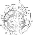
在图6中以示例方式显示了双叶片组结构的一个备选实施例。这种结构由具有足够叶片厚度的内径旋流器组成,从而提供至外径通道的毂部或分配环的气体通道。该备选结构被设计成可由单件铸件生产出来。各叶片256,257在周向上偏离一个恰当的角度,以便允许环-支柱-环的热应力分散在分配环上。各旋流器组件中的叶片也可结合有倾斜的或非径向的定向,这将进一步减少环-支柱-环的应力。由于孔的径向定向,利用简单的钻孔操作就可在这个组件中形成燃料入口孔268,270。位于内径毂部252上的燃料注入孔(入口)268可轴向地定位在叶片256和分配环253的前方,以允许在标号270处进行钻孔。应当注意到,内毂部上钻有交替的孔,其用于使燃料流入内径旋流器216,并穿过内毂部252(如在标号272处)和内径旋流器256而到达外径毂部或分配环253,以便形成用于使燃料流入外径旋流器218中的燃料入口孔263。在典型的旋流喷嘴设计中,燃料供给通道是通过插入式EDM工艺或熔模铸造中的陶瓷型芯来生产的,这两者的成本都很高。另外,图5所示实施例的燃料注入孔163通常是通过插入式EDM工艺穿过叶片侧面来生产的,其成本也很高。因此,图6所示的实施例设计成能够实现快速和低成本的可制造性。An alternative embodiment of a dual blade set configuration is shown by way of example in FIG. 6 . This structure consists of an inner diameter swirler with sufficient vane thickness to provide gas passage to the hub or distribution ring of the outer diameter passage. This alternative structure is designed to be produced from a single casting. The
图7和8显示了本发明的一个备选实施例。在该实施例中,气体燃料经由为导向叶片通道358供料的入口和环形通道360而进入旋流器组件,从而流入分配环353的中空内部359和燃料入口孔363中,该燃料入口孔363形成在分配环中,并处于垂直于中心线的径向上。如上述实施例中所示的那样,气体燃料在旋流器组件350中开始与燃烧空气混合,并在由中心体延伸部分364和旋流器护罩延伸部分366所形成的环形通道362中完成燃料/空气的混合。在离开环形通道之后,燃料/空气混合气进入燃烧室反应区,并在那里进行燃烧。在该实施例中,如图4所示实施例中的那样,分配环或叶片353的后缘是流线型弯曲的,即为椭圆形结构,从而减小了分配环353之后的尾流区域或空气动力学上的分离区域。Figures 7 and 8 show an alternative embodiment of the invention. In this embodiment, the gaseous fuel enters the swirler assembly via the inlet feeding the
虽然已经结合目前被视为最实用且最优选的实施例来介绍了本发明,但是应当理解,本发明并不限于所公开的实施例,相反,本发明旨在覆盖包括在所附权利要求的精神和范围内的各种修改和等效设置。因此,保留本发明的目的而在细微之处略有不同的其它实施例也是可以的。一种这样的实施例利用了相对于中心体轴线沿相同方向旋转但处于明显不同的涡流角下的两个旋流器,在这两个涡流流之间实现了很高的剪切,从而实现了强烈的湍流混合。例如,20度涡流角的内旋流器和60度涡流角的外旋流器可实现与优选实施例类似的混合,但导致更高的残余涡流,从而导致在火焰区中具有更强的再循环和火焰稳定性。另一备选实施例可包含具有不同涡流角的两个以上的旋流器,例如三个同轴的旋流器,其中内、外旋流器同向旋转,而中间的旋流器逆向旋转。在第三种可能的备选实施例中,一个或多个旋流器可主要地在径向而非在轴向上流动,或者在径向和轴向的组合方向上流动。While the present invention has been described in connection with what are presently considered to be the most practical and preferred embodiments, it is to be understood that the invention is not limited to the disclosed embodiments, but rather the invention is intended to cover all aspects contained in the appended claims. Various modifications and equivalent settings in spirit and scope. Therefore, other embodiments that differ slightly in subtle points are possible while maintaining the object of the present invention. One such embodiment utilizes two swirlers rotating in the same direction relative to the centerbody axis, but at significantly different swirl angles, between which a high shear is achieved to achieve intense turbulent mixing. For example, an inner swirler with a swirl angle of 20 degrees and an outer swirler with a swirl angle of 60 degrees would achieve similar mixing as the preferred embodiment, but result in a higher residual swirl, resulting in a stronger regeneration in the flame zone. cycle and flame stability. Another alternative embodiment may include more than two swirlers with different swirl angles, for example three coaxial swirlers, where the inner and outer swirlers rotate in the same direction and the middle swirler rotates in the opposite direction . In a third possible alternative embodiment, one or more swirlers may flow predominantly radially rather than axially, or in a combined radial and axial direction.
Claims (10)
Applications Claiming Priority (2)
| Application Number | Priority Date | Filing Date | Title |
|---|---|---|---|
| US10/862427 | 2004-06-08 | ||
| US10/862,427US6993916B2 (en) | 2004-06-08 | 2004-06-08 | Burner tube and method for mixing air and gas in a gas turbine engine |
Publications (2)
| Publication Number | Publication Date |
|---|---|
| CN1707163A CN1707163A (en) | 2005-12-14 |
| CN100554785Ctrue CN100554785C (en) | 2009-10-28 |
Family
ID=35446172
Family Applications (1)
| Application Number | Title | Priority Date | Filing Date |
|---|---|---|---|
| CNB2005100785224AExpired - Fee RelatedCN100554785C (en) | 2004-06-08 | 2005-06-08 | Be used for combustion tube and method that the air of gas turbine is mixed |
Country Status (4)
| Country | Link |
|---|---|
| US (1) | US6993916B2 (en) |
| JP (1) | JP2005351616A (en) |
| CN (1) | CN100554785C (en) |
| DE (1) | DE102005024062B4 (en) |
Cited By (1)
| Publication number | Priority date | Publication date | Assignee | Title |
|---|---|---|---|---|
| US20210268520A1 (en)* | 2019-04-08 | 2021-09-02 | Fmc Technologies, Inc. | Cyclone separator and methods of using same |
Families Citing this family (196)
| Publication number | Priority date | Publication date | Assignee | Title |
|---|---|---|---|---|
| US7126182B2 (en)* | 2004-08-13 | 2006-10-24 | Micron Technology, Inc. | Memory circuitry |
| JP2006300448A (en)* | 2005-04-22 | 2006-11-02 | Mitsubishi Heavy Ind Ltd | Combustor for gas turbine |
| JP4486549B2 (en)* | 2005-06-06 | 2010-06-23 | 三菱重工業株式会社 | Gas turbine combustor |
| JP4476176B2 (en)* | 2005-06-06 | 2010-06-09 | 三菱重工業株式会社 | Gas turbine premixed combustion burner |
| US20070074518A1 (en)* | 2005-09-30 | 2007-04-05 | Solar Turbines Incorporated | Turbine engine having acoustically tuned fuel nozzle |
| US7703288B2 (en)* | 2005-09-30 | 2010-04-27 | Solar Turbines Inc. | Fuel nozzle having swirler-integrated radial fuel jet |
| GB2435508B (en)* | 2006-02-22 | 2011-08-03 | Siemens Ag | A swirler for use in a burner of a gas turbine engine |
| US8308477B2 (en)* | 2006-03-01 | 2012-11-13 | Honeywell International Inc. | Industrial burner |
| JP4418442B2 (en)* | 2006-03-30 | 2010-02-17 | 三菱重工業株式会社 | Gas turbine combustor and combustion control method |
| US20070277530A1 (en)* | 2006-05-31 | 2007-12-06 | Constantin Alexandru Dinu | Inlet flow conditioner for gas turbine engine fuel nozzle |
| US7603863B2 (en)* | 2006-06-05 | 2009-10-20 | General Electric Company | Secondary fuel injection from stage one nozzle |
| US20080078182A1 (en)* | 2006-09-29 | 2008-04-03 | Andrei Tristan Evulet | Premixing device, gas turbines comprising the premixing device, and methods of use |
| US20080078183A1 (en)* | 2006-10-03 | 2008-04-03 | General Electric Company | Liquid fuel enhancement for natural gas swirl stabilized nozzle and method |
| US8015814B2 (en)* | 2006-10-24 | 2011-09-13 | Caterpillar Inc. | Turbine engine having folded annular jet combustor |
| US20080104961A1 (en)* | 2006-11-08 | 2008-05-08 | Ronald Scott Bunker | Method and apparatus for enhanced mixing in premixing devices |
| US8117845B2 (en)* | 2007-04-27 | 2012-02-21 | General Electric Company | Systems to facilitate reducing flashback/flame holding in combustion systems |
| US20080276622A1 (en)* | 2007-05-07 | 2008-11-13 | Thomas Edward Johnson | Fuel nozzle and method of fabricating the same |
| JP5412283B2 (en)* | 2007-08-10 | 2014-02-12 | 川崎重工業株式会社 | Combustion device |
| US20090056336A1 (en) | 2007-08-28 | 2009-03-05 | General Electric Company | Gas turbine premixer with radially staged flow passages and method for mixing air and gas in a gas turbine |
| DE102007043626A1 (en) | 2007-09-13 | 2009-03-19 | Rolls-Royce Deutschland Ltd & Co Kg | Gas turbine lean burn burner with fuel nozzle with controlled fuel inhomogeneity |
| US20090111063A1 (en)* | 2007-10-29 | 2009-04-30 | General Electric Company | Lean premixed, radial inflow, multi-annular staged nozzle, can-annular, dual-fuel combustor |
| JP4959524B2 (en) | 2007-11-29 | 2012-06-27 | 三菱重工業株式会社 | Burning burner |
| FR2925657B1 (en)* | 2007-12-19 | 2010-01-29 | Mer Joseph Le | DEVICE AND METHOD FOR STABILIZING THE PRESSURE AND FLOW OF A GAS MIXTURE SUPPLYING A SURFACE COMBUSTION CYLINDRICAL BURNER |
| US20090173074A1 (en)* | 2008-01-03 | 2009-07-09 | General Electric Company | Integrated fuel nozzle ifc |
| DE102008014744A1 (en)* | 2008-03-18 | 2009-09-24 | Rolls-Royce Deutschland Ltd & Co Kg | Gas turbine burner for a gas turbine with a rinsing mechanism for a fuel nozzle |
| WO2009120779A2 (en) | 2008-03-28 | 2009-10-01 | Exxonmobil Upstream Research Company | Low emission power generation and hydrocarbon recovery systems and methods |
| EP2276559A4 (en)* | 2008-03-28 | 2017-10-18 | Exxonmobil Upstream Research Company | Low emission power generation and hydrocarbon recovery systems and methods |
| US20090249789A1 (en)* | 2008-04-08 | 2009-10-08 | Baifang Zuo | Burner tube premixer and method for mixing air and gas in a gas turbine engine |
| US9188341B2 (en)* | 2008-04-11 | 2015-11-17 | General Electric Company | Fuel nozzle |
| US20090255118A1 (en)* | 2008-04-11 | 2009-10-15 | General Electric Company | Method of manufacturing mixers |
| EP2112433A1 (en)* | 2008-04-23 | 2009-10-28 | Siemens Aktiengesellschaft | Mixing chamber |
| US7578130B1 (en) | 2008-05-20 | 2009-08-25 | General Electric Company | Methods and systems for combustion dynamics reduction |
| US8147121B2 (en)* | 2008-07-09 | 2012-04-03 | General Electric Company | Pre-mixing apparatus for a turbine engine |
| US20100011770A1 (en)* | 2008-07-21 | 2010-01-21 | Ronald James Chila | Gas Turbine Premixer with Cratered Fuel Injection Sites |
| US8112999B2 (en)* | 2008-08-05 | 2012-02-14 | General Electric Company | Turbomachine injection nozzle including a coolant delivery system |
| US20100078506A1 (en)* | 2008-09-30 | 2010-04-01 | General Electric Company | Circumferential fuel circuit divider |
| EP2312215A1 (en)* | 2008-10-01 | 2011-04-20 | Siemens Aktiengesellschaft | Burner and Method for Operating a Burner |
| EA026915B1 (en) | 2008-10-14 | 2017-05-31 | Эксонмобил Апстрим Рисерч Компани | Methods and systems for controlling the products of combustion |
| US8113002B2 (en)* | 2008-10-17 | 2012-02-14 | General Electric Company | Combustor burner vanelets |
| US8312722B2 (en)* | 2008-10-23 | 2012-11-20 | General Electric Company | Flame holding tolerant fuel and air premixer for a gas turbine combustor |
| KR101049359B1 (en)* | 2008-10-31 | 2011-07-13 | 한국전력공사 | Triple swirl gas turbine combustor |
| US8220270B2 (en)* | 2008-10-31 | 2012-07-17 | General Electric Company | Method and apparatus for affecting a recirculation zone in a cross flow |
| US9822649B2 (en)* | 2008-11-12 | 2017-11-21 | General Electric Company | Integrated combustor and stage 1 nozzle in a gas turbine and method |
| CN101408315B (en)* | 2008-11-27 | 2010-06-02 | 浙江大学 | A Low Noise and High Efficiency Gas Turbine Combustor |
| US8505304B2 (en)* | 2008-12-01 | 2013-08-13 | General Electric Company | Fuel nozzle detachable burner tube with baffle plate assembly |
| US20100170253A1 (en)* | 2009-01-07 | 2010-07-08 | General Electric Company | Method and apparatus for fuel injection in a turbine engine |
| US8104286B2 (en) | 2009-01-07 | 2012-01-31 | General Electric Company | Methods and systems to enhance flame holding in a gas turbine engine |
| US8297059B2 (en)* | 2009-01-22 | 2012-10-30 | General Electric Company | Nozzle for a turbomachine |
| US9140454B2 (en)* | 2009-01-23 | 2015-09-22 | General Electric Company | Bundled multi-tube nozzle for a turbomachine |
| US8555646B2 (en)* | 2009-01-27 | 2013-10-15 | General Electric Company | Annular fuel and air co-flow premixer |
| US20100192582A1 (en)* | 2009-02-04 | 2010-08-05 | Robert Bland | Combustor nozzle |
| US8539773B2 (en)* | 2009-02-04 | 2013-09-24 | General Electric Company | Premixed direct injection nozzle for highly reactive fuels |
| US8851402B2 (en)* | 2009-02-12 | 2014-10-07 | General Electric Company | Fuel injection for gas turbine combustors |
| US9513009B2 (en) | 2009-02-18 | 2016-12-06 | Rolls-Royce Plc | Fuel nozzle having aerodynamically shaped helical turning vanes |
| US8443607B2 (en)* | 2009-02-20 | 2013-05-21 | General Electric Company | Coaxial fuel and air premixer for a gas turbine combustor |
| EP2233836B1 (en)* | 2009-03-23 | 2015-07-29 | Siemens Aktiengesellschaft | Swirler, method for reducing flashback in a burner with at least one swirler and burner |
| US8689559B2 (en)* | 2009-03-30 | 2014-04-08 | General Electric Company | Secondary combustion system for reducing the level of emissions generated by a turbomachine |
| US8333075B2 (en)* | 2009-04-16 | 2012-12-18 | General Electric Company | Gas turbine premixer with internal cooling |
| US8256226B2 (en)* | 2009-04-23 | 2012-09-04 | General Electric Company | Radial lean direct injection burner |
| US8260523B2 (en)* | 2009-05-04 | 2012-09-04 | General Electric Company | Method for detecting gas turbine engine flashback |
| US20100287938A1 (en)* | 2009-05-14 | 2010-11-18 | General Electric Company | Cross flow vane |
| US20100293956A1 (en)* | 2009-05-21 | 2010-11-25 | General Electric Company | Turbine fuel nozzle having premixer with auxiliary vane |
| US20100300102A1 (en)* | 2009-05-28 | 2010-12-02 | General Electric Company | Method and apparatus for air and fuel injection in a turbine |
| EP2270398A1 (en)* | 2009-06-30 | 2011-01-05 | Siemens Aktiengesellschaft | Burner, especially for gas turbines |
| DE102009038848A1 (en)* | 2009-08-26 | 2011-03-03 | Siemens Aktiengesellschaft | Burner, in particular for gas turbines |
| US8365532B2 (en)* | 2009-09-30 | 2013-02-05 | General Electric Company | Apparatus and method for a gas turbine nozzle |
| RU2506499C2 (en)* | 2009-11-09 | 2014-02-10 | Дженерал Электрик Компани | Fuel atomisers of gas turbine with opposite swirling directions |
| EP2499332B1 (en) | 2009-11-12 | 2017-05-24 | Exxonmobil Upstream Research Company | Integrated system for power generation and method for low emission hydrocarbon recovery with power generation |
| CN101709884B (en)* | 2009-11-25 | 2012-07-04 | 北京航空航天大学 | Premixing and pre-evaporating combustion chamber |
| US8024932B1 (en) | 2010-04-07 | 2011-09-27 | General Electric Company | System and method for a combustor nozzle |
| US8453454B2 (en) | 2010-04-14 | 2013-06-04 | General Electric Company | Coannular oil injection nozzle |
| US8752386B2 (en)* | 2010-05-25 | 2014-06-17 | Siemens Energy, Inc. | Air/fuel supply system for use in a gas turbine engine |
| TWI564475B (en) | 2010-07-02 | 2017-01-01 | 艾克頌美孚上游研究公司 | Low emission triple-cycle power generation systems and methods |
| CN102971508B (en) | 2010-07-02 | 2016-06-01 | 埃克森美孚上游研究公司 | CO2 separation system and method for separating CO2 |
| CA2801492C (en) | 2010-07-02 | 2017-09-26 | Exxonmobil Upstream Research Company | Stoichiometric combustion with exhaust gas recirculation and direct contact cooler |
| MX354587B (en) | 2010-07-02 | 2018-03-12 | Exxonmobil Upstream Res Company Star | Stoichiometric combustion of enriched air with exhaust gas recirculation. |
| US8959921B2 (en) | 2010-07-13 | 2015-02-24 | General Electric Company | Flame tolerant secondary fuel nozzle |
| US9435537B2 (en)* | 2010-11-30 | 2016-09-06 | General Electric Company | System and method for premixer wake and vortex filling for enhanced flame-holding resistance |
| US8863525B2 (en) | 2011-01-03 | 2014-10-21 | General Electric Company | Combustor with fuel staggering for flame holding mitigation |
| US8579211B2 (en)* | 2011-01-06 | 2013-11-12 | General Electric Company | System and method for enhancing flow in a nozzle |
| US20120180494A1 (en)* | 2011-01-14 | 2012-07-19 | General Electric Company | Turbine fuel nozzle assembly |
| US8528839B2 (en)* | 2011-01-19 | 2013-09-10 | General Electric Company | Combustor nozzle and method for fabricating the combustor nozzle |
| US10317081B2 (en)* | 2011-01-26 | 2019-06-11 | United Technologies Corporation | Fuel injector assembly |
| US8875516B2 (en)* | 2011-02-04 | 2014-11-04 | General Electric Company | Turbine combustor configured for high-frequency dynamics mitigation and related method |
| TWI563166B (en) | 2011-03-22 | 2016-12-21 | Exxonmobil Upstream Res Co | Integrated generation systems and methods for generating power |
| TWI563165B (en) | 2011-03-22 | 2016-12-21 | Exxonmobil Upstream Res Co | Power generation system and method for generating power |
| TWI593872B (en) | 2011-03-22 | 2017-08-01 | 艾克頌美孚上游研究公司 | Integrated system and method of generating power |
| TWI564474B (en) | 2011-03-22 | 2017-01-01 | 艾克頌美孚上游研究公司 | Integrated systems for controlling stoichiometric combustion in turbine systems and methods of generating power using the same |
| US8307660B2 (en)* | 2011-04-11 | 2012-11-13 | General Electric Company | Combustor nozzle and method for supplying fuel to a combustor |
| US8893500B2 (en) | 2011-05-18 | 2014-11-25 | Solar Turbines Inc. | Lean direct fuel injector |
| US8919132B2 (en) | 2011-05-18 | 2014-12-30 | Solar Turbines Inc. | Method of operating a gas turbine engine |
| US20120312890A1 (en)* | 2011-06-10 | 2012-12-13 | General Electric Company | Fuel Nozzle with Swirling Vanes |
| US9046262B2 (en) | 2011-06-27 | 2015-06-02 | General Electric Company | Premixer fuel nozzle for gas turbine engine |
| US9388985B2 (en) | 2011-07-29 | 2016-07-12 | General Electric Company | Premixing apparatus for gas turbine system |
| US20130040254A1 (en)* | 2011-08-08 | 2013-02-14 | General Electric Company | System and method for monitoring a combustor |
| US8950188B2 (en) | 2011-09-09 | 2015-02-10 | General Electric Company | Turning guide for combustion fuel nozzle in gas turbine and method to turn fuel flow entering combustion chamber |
| WO2013040323A2 (en) | 2011-09-14 | 2013-03-21 | Anthony Martinez | Providing oxidation to a gas turbine engine |
| US8850821B2 (en) | 2011-10-07 | 2014-10-07 | General Electric Company | System for fuel injection in a fuel nozzle |
| US8955329B2 (en) | 2011-10-21 | 2015-02-17 | General Electric Company | Diffusion nozzles for low-oxygen fuel nozzle assembly and method |
| US9182124B2 (en) | 2011-12-15 | 2015-11-10 | Solar Turbines Incorporated | Gas turbine and fuel injector for the same |
| US9810050B2 (en) | 2011-12-20 | 2017-11-07 | Exxonmobil Upstream Research Company | Enhanced coal-bed methane production |
| US20130192243A1 (en)* | 2012-01-31 | 2013-08-01 | Matthew Patrick Boespflug | Fuel nozzle for a gas turbine engine and method of operating the same |
| US20130205799A1 (en)* | 2012-02-15 | 2013-08-15 | Donald Mark Bailey | Outer Fuel Nozzle Inlet Flow Conditioner Interface to End Cap |
| US20130219899A1 (en)* | 2012-02-27 | 2013-08-29 | General Electric Company | Annular premixed pilot in fuel nozzle |
| JP5486619B2 (en) | 2012-02-28 | 2014-05-07 | 株式会社日立製作所 | Gas turbine combustor and operation method thereof |
| CN102607060A (en)* | 2012-03-13 | 2012-07-25 | 浙江科技学院 | Method for controlling instability of combustion heat sound |
| US9353682B2 (en) | 2012-04-12 | 2016-05-31 | General Electric Company | Methods, systems and apparatus relating to combustion turbine power plants with exhaust gas recirculation |
| US8966907B2 (en)* | 2012-04-16 | 2015-03-03 | General Electric Company | Turbine combustor system having aerodynamic feed cap |
| US9784185B2 (en) | 2012-04-26 | 2017-10-10 | General Electric Company | System and method for cooling a gas turbine with an exhaust gas provided by the gas turbine |
| US10273880B2 (en) | 2012-04-26 | 2019-04-30 | General Electric Company | System and method of recirculating exhaust gas for use in a plurality of flow paths in a gas turbine engine |
| US8925323B2 (en)* | 2012-04-30 | 2015-01-06 | General Electric Company | Fuel/air premixing system for turbine engine |
| US9267690B2 (en) | 2012-05-29 | 2016-02-23 | General Electric Company | Turbomachine combustor nozzle including a monolithic nozzle component and method of forming the same |
| WO2013188880A1 (en)* | 2012-06-15 | 2013-12-19 | Cummins Ip, Inc. | Reductant decomposition and mixing system |
| US9115896B2 (en) | 2012-07-31 | 2015-08-25 | General Electric Company | Fuel-air mixer for use with a combustor assembly |
| CN104471317B (en)* | 2012-08-06 | 2016-09-07 | 西门子公司 | Local improvement of air and fuel mixing in a combustor with a swirl generator with blade ends intersecting in the outer region |
| US9611756B2 (en) | 2012-11-02 | 2017-04-04 | General Electric Company | System and method for protecting components in a gas turbine engine with exhaust gas recirculation |
| US10107495B2 (en) | 2012-11-02 | 2018-10-23 | General Electric Company | Gas turbine combustor control system for stoichiometric combustion in the presence of a diluent |
| US9803865B2 (en) | 2012-12-28 | 2017-10-31 | General Electric Company | System and method for a turbine combustor |
| US10161312B2 (en) | 2012-11-02 | 2018-12-25 | General Electric Company | System and method for diffusion combustion with fuel-diluent mixing in a stoichiometric exhaust gas recirculation gas turbine system |
| US9869279B2 (en) | 2012-11-02 | 2018-01-16 | General Electric Company | System and method for a multi-wall turbine combustor |
| US9708977B2 (en) | 2012-12-28 | 2017-07-18 | General Electric Company | System and method for reheat in gas turbine with exhaust gas recirculation |
| US9574496B2 (en) | 2012-12-28 | 2017-02-21 | General Electric Company | System and method for a turbine combustor |
| US10215412B2 (en) | 2012-11-02 | 2019-02-26 | General Electric Company | System and method for load control with diffusion combustion in a stoichiometric exhaust gas recirculation gas turbine system |
| US9631815B2 (en) | 2012-12-28 | 2017-04-25 | General Electric Company | System and method for a turbine combustor |
| US9599070B2 (en) | 2012-11-02 | 2017-03-21 | General Electric Company | System and method for oxidant compression in a stoichiometric exhaust gas recirculation gas turbine system |
| US10208677B2 (en) | 2012-12-31 | 2019-02-19 | General Electric Company | Gas turbine load control system |
| US9581081B2 (en) | 2013-01-13 | 2017-02-28 | General Electric Company | System and method for protecting components in a gas turbine engine with exhaust gas recirculation |
| US9512759B2 (en) | 2013-02-06 | 2016-12-06 | General Electric Company | System and method for catalyst heat utilization for gas turbine with exhaust gas recirculation |
| US9938861B2 (en) | 2013-02-21 | 2018-04-10 | Exxonmobil Upstream Research Company | Fuel combusting method |
| TW201502356A (en) | 2013-02-21 | 2015-01-16 | Exxonmobil Upstream Res Co | Reducing oxygen in a gas turbine exhaust |
| US9297535B2 (en)* | 2013-02-25 | 2016-03-29 | General Electric Company | Fuel/air mixing system for fuel nozzle |
| WO2014133406A1 (en) | 2013-02-28 | 2014-09-04 | General Electric Company | System and method for a turbine combustor |
| US9618261B2 (en) | 2013-03-08 | 2017-04-11 | Exxonmobil Upstream Research Company | Power generation and LNG production |
| US9879862B2 (en)* | 2013-03-08 | 2018-01-30 | Rolls-Royce North American Technologies, Inc. | Gas turbine engine afterburner |
| CA2902479C (en) | 2013-03-08 | 2017-11-07 | Exxonmobil Upstream Research Company | Power generation and methane recovery from methane hydrates |
| TW201500635A (en) | 2013-03-08 | 2015-01-01 | Exxonmobil Upstream Res Co | Processing exhaust for use in enhanced oil recovery |
| US20140250945A1 (en) | 2013-03-08 | 2014-09-11 | Richard A. Huntington | Carbon Dioxide Recovery |
| US9322559B2 (en) | 2013-04-17 | 2016-04-26 | General Electric Company | Fuel nozzle having swirler vane and fuel injection peg arrangement |
| US20140318150A1 (en)* | 2013-04-25 | 2014-10-30 | Khalid Oumejjoud | Removable swirler assembly for a combustion liner |
| US9835089B2 (en) | 2013-06-28 | 2017-12-05 | General Electric Company | System and method for a fuel nozzle |
| TWI654368B (en) | 2013-06-28 | 2019-03-21 | 美商艾克頌美孚上游研究公司 | System, method and media for controlling exhaust gas flow in an exhaust gas recirculation gas turbine system |
| US9617914B2 (en) | 2013-06-28 | 2017-04-11 | General Electric Company | Systems and methods for monitoring gas turbine systems having exhaust gas recirculation |
| US9631542B2 (en) | 2013-06-28 | 2017-04-25 | General Electric Company | System and method for exhausting combustion gases from gas turbine engines |
| US9587510B2 (en) | 2013-07-30 | 2017-03-07 | General Electric Company | System and method for a gas turbine engine sensor |
| US9903588B2 (en) | 2013-07-30 | 2018-02-27 | General Electric Company | System and method for barrier in passage of combustor of gas turbine engine with exhaust gas recirculation |
| US9951658B2 (en) | 2013-07-31 | 2018-04-24 | General Electric Company | System and method for an oxidant heating system |
| EP3074697B1 (en) | 2013-11-27 | 2019-04-10 | General Electric Company | Fuel nozzle with fluid lock and purge apparatus |
| US10030588B2 (en) | 2013-12-04 | 2018-07-24 | General Electric Company | Gas turbine combustor diagnostic system and method |
| US9752458B2 (en) | 2013-12-04 | 2017-09-05 | General Electric Company | System and method for a gas turbine engine |
| CA2933536C (en) | 2013-12-23 | 2018-06-26 | General Electric Company | Fuel nozzle structure for air-assisted fuel injection |
| CA2933539C (en) | 2013-12-23 | 2022-01-18 | General Electric Company | Fuel nozzle with flexible support structures |
| US10227920B2 (en) | 2014-01-15 | 2019-03-12 | General Electric Company | Gas turbine oxidant separation system |
| US9915200B2 (en) | 2014-01-21 | 2018-03-13 | General Electric Company | System and method for controlling the combustion process in a gas turbine operating with exhaust gas recirculation |
| US9863267B2 (en) | 2014-01-21 | 2018-01-09 | General Electric Company | System and method of control for a gas turbine engine |
| US10079564B2 (en) | 2014-01-27 | 2018-09-18 | General Electric Company | System and method for a stoichiometric exhaust gas recirculation gas turbine system |
| US20150276225A1 (en)* | 2014-03-27 | 2015-10-01 | General Electric Company | Combustor wth pre-mixing fuel nozzle assembly |
| US9534788B2 (en) | 2014-04-03 | 2017-01-03 | General Electric Company | Air fuel premixer for low emissions gas turbine combustor |
| US10047633B2 (en) | 2014-05-16 | 2018-08-14 | General Electric Company | Bearing housing |
| US10655542B2 (en) | 2014-06-30 | 2020-05-19 | General Electric Company | Method and system for startup of gas turbine system drive trains with exhaust gas recirculation |
| US10060359B2 (en) | 2014-06-30 | 2018-08-28 | General Electric Company | Method and system for combustion control for gas turbine system with exhaust gas recirculation |
| US9885290B2 (en) | 2014-06-30 | 2018-02-06 | General Electric Company | Erosion suppression system and method in an exhaust gas recirculation gas turbine system |
| JP6430756B2 (en)* | 2014-09-19 | 2018-11-28 | 三菱日立パワーシステムズ株式会社 | Combustion burner and combustor, and gas turbine |
| JP5913503B2 (en) | 2014-09-19 | 2016-04-27 | 三菱重工業株式会社 | Combustion burner and combustor, and gas turbine |
| CA2963956C (en)* | 2014-10-17 | 2022-10-04 | Nuovo Pignone Srl | Method for reducing nox emission in a gas turbine, air fuel mixer, gas turbine and swirler |
| US9819292B2 (en) | 2014-12-31 | 2017-11-14 | General Electric Company | Systems and methods to respond to grid overfrequency events for a stoichiometric exhaust recirculation gas turbine |
| US9869247B2 (en) | 2014-12-31 | 2018-01-16 | General Electric Company | Systems and methods of estimating a combustion equivalence ratio in a gas turbine with exhaust gas recirculation |
| US10788212B2 (en) | 2015-01-12 | 2020-09-29 | General Electric Company | System and method for an oxidant passageway in a gas turbine system with exhaust gas recirculation |
| US10094566B2 (en) | 2015-02-04 | 2018-10-09 | General Electric Company | Systems and methods for high volumetric oxidant flow in gas turbine engine with exhaust gas recirculation |
| US10316746B2 (en) | 2015-02-04 | 2019-06-11 | General Electric Company | Turbine system with exhaust gas recirculation, separation and extraction |
| US10253690B2 (en) | 2015-02-04 | 2019-04-09 | General Electric Company | Turbine system with exhaust gas recirculation, separation and extraction |
| US10267270B2 (en) | 2015-02-06 | 2019-04-23 | General Electric Company | Systems and methods for carbon black production with a gas turbine engine having exhaust gas recirculation |
| US10145269B2 (en) | 2015-03-04 | 2018-12-04 | General Electric Company | System and method for cooling discharge flow |
| US10480792B2 (en) | 2015-03-06 | 2019-11-19 | General Electric Company | Fuel staging in a gas turbine engine |
| US10767900B2 (en) | 2015-05-14 | 2020-09-08 | Lochinvar, Llc | Burner with flow distribution member |
| US10352567B2 (en) | 2015-10-09 | 2019-07-16 | General Electric Company | Fuel-air premixer for a gas turbine |
| CN105716113B (en)* | 2016-02-06 | 2019-03-12 | 中国科学院工程热物理研究所 | Bispin premix burner |
| EP3225915B1 (en) | 2016-03-31 | 2019-02-06 | Rolls-Royce plc | Fuel injector and method of manufactering the same |
| US10234142B2 (en)* | 2016-04-15 | 2019-03-19 | Solar Turbines Incorporated | Fuel delivery methods in combustion engine using wide range of gaseous fuels |
| CN106090921B (en)* | 2016-06-22 | 2018-04-17 | 江苏大学 | A kind of burner that can be used for multi fuel blending combustion phenomena research with dual rotary inflow channel |
| RU2633982C1 (en)* | 2016-06-29 | 2017-10-20 | Акционерное общество "ОДК-Авиадвигатель" | Flame tube of gas turbine engine combustion chamber |
| US20180209639A1 (en)* | 2017-01-20 | 2018-07-26 | Marc Mahé | Gas heater conversion system and method |
| US10941938B2 (en)* | 2018-02-22 | 2021-03-09 | Delavan Inc. | Fuel injectors including gas fuel injection |
| KR102070908B1 (en)* | 2018-02-23 | 2020-03-02 | 두산중공업 주식회사 | Nozzle for combustor, combustor, and gas turbine including the same |
| US10890329B2 (en)* | 2018-03-01 | 2021-01-12 | General Electric Company | Fuel injector assembly for gas turbine engine |
| KR102111644B1 (en)* | 2019-06-11 | 2020-05-15 | 두산중공업 주식회사 | Combustor and gas turbine with multiple swirlers formed in different shapes |
| US11713881B2 (en)* | 2020-01-08 | 2023-08-01 | General Electric Company | Premixer for a combustor |
| CN111520750B (en)* | 2020-03-25 | 2022-05-20 | 西北工业大学 | New type combustion chamber head fuel injection structure |
| US11187414B2 (en)* | 2020-03-31 | 2021-11-30 | General Electric Company | Fuel nozzle with improved swirler vane structure |
| KR102363091B1 (en)* | 2020-07-06 | 2022-02-14 | 두산중공업 주식회사 | Nozzle for combustor, combustor, and gas turbine including the same |
| KR102322596B1 (en)* | 2020-07-17 | 2021-11-05 | 두산중공업 주식회사 | Nozzle assembly for combustor and gas turbine combustor including the same |
| US11754288B2 (en)* | 2020-12-09 | 2023-09-12 | General Electric Company | Combustor mixing assembly |
| CN113047944A (en)* | 2021-03-09 | 2021-06-29 | 魏福宽 | Multifunctional cyclone mechanical supercharger |
| CN113124405B (en)* | 2021-05-14 | 2024-04-30 | 福建华夏蓝天科技有限公司 | Automatically adjustable flame stabilizing disc and burner with same |
| CN114278937A (en)* | 2021-12-30 | 2022-04-05 | 乔治洛德方法研究和开发液化空气有限公司 | Burner, burner module comprising same, burner assembly and heating device |
| KR102714020B1 (en)* | 2022-11-30 | 2024-10-07 | 두산에너빌리티 주식회사 | Nozzle assembly, combustor and gas turbine comprising the same |
| WO2025042376A1 (en)* | 2023-08-23 | 2025-02-27 | Istanbul Teknik Universitesi | Partially premixed combustion chamber system stabilised by a swirler and a bluff body |
Family Cites Families (41)
| Publication number | Priority date | Publication date | Assignee | Title |
|---|---|---|---|---|
| US3917173A (en)* | 1972-04-21 | 1975-11-04 | Stal Laval Turbin Ab | Atomizing apparatus for finely distributing a liquid in an air stream |
| US3808803A (en)* | 1973-03-15 | 1974-05-07 | Us Navy | Anticarbon device for the scroll fuel carburetor |
| FR2235274B1 (en)* | 1973-06-28 | 1976-09-17 | Snecma | |
| US3972182A (en)* | 1973-09-10 | 1976-08-03 | General Electric Company | Fuel injection apparatus |
| US5341477A (en)* | 1989-02-24 | 1994-08-23 | Digital Equipment Corporation | Broker for computer network server selection |
| US5224333A (en)* | 1990-03-13 | 1993-07-06 | Delavan Inc | Simplex airblast fuel injection |
| US5165241A (en)* | 1991-02-22 | 1992-11-24 | General Electric Company | Air fuel mixer for gas turbine combustor |
| US5259184A (en)* | 1992-03-30 | 1993-11-09 | General Electric Company | Dry low NOx single stage dual mode combustor construction for a gas turbine |
| US5251447A (en)* | 1992-10-01 | 1993-10-12 | General Electric Company | Air fuel mixer for gas turbine combustor |
| US5351477A (en)* | 1993-12-21 | 1994-10-04 | General Electric Company | Dual fuel mixer for gas turbine combustor |
| GB9326367D0 (en)* | 1993-12-23 | 1994-02-23 | Rolls Royce Plc | Fuel injection apparatus |
| US5638682A (en)* | 1994-09-23 | 1997-06-17 | General Electric Company | Air fuel mixer for gas turbine combustor having slots at downstream end of mixing duct |
| US5590529A (en)* | 1994-09-26 | 1997-01-07 | General Electric Company | Air fuel mixer for gas turbine combustor |
| US5613363A (en)* | 1994-09-26 | 1997-03-25 | General Electric Company | Air fuel mixer for gas turbine combustor |
| US5943866A (en)* | 1994-10-03 | 1999-08-31 | General Electric Company | Dynamically uncoupled low NOx combustor having multiple premixers with axial staging |
| US5722230A (en)* | 1995-08-08 | 1998-03-03 | General Electric Co. | Center burner in a multi-burner combustor |
| US5822992A (en)* | 1995-10-19 | 1998-10-20 | General Electric Company | Low emissions combustor premixer |
| US5647215A (en)* | 1995-11-07 | 1997-07-15 | Westinghouse Electric Corporation | Gas turbine combustor with turbulence enhanced mixing fuel injectors |
| US5675971A (en)* | 1996-01-02 | 1997-10-14 | General Electric Company | Dual fuel mixer for gas turbine combustor |
| US5680766A (en)* | 1996-01-02 | 1997-10-28 | General Electric Company | Dual fuel mixer for gas turbine combustor |
| US5916142A (en)* | 1996-10-21 | 1999-06-29 | General Electric Company | Self-aligning swirler with ball joint |
| US5901548A (en)* | 1996-12-23 | 1999-05-11 | General Electric Company | Air assist fuel atomization in a gas turbine engine |
| JPH1193980A (en)* | 1997-09-19 | 1999-04-06 | Kubota Corp | Work vehicle |
| US5983642A (en)* | 1997-10-13 | 1999-11-16 | Siemens Westinghouse Power Corporation | Combustor with two stage primary fuel tube with concentric members and flow regulating |
| GB9726697D0 (en)* | 1997-12-18 | 1998-02-18 | Secr Defence | Fuel injector |
| US6550251B1 (en)* | 1997-12-18 | 2003-04-22 | General Electric Company | Venturiless swirl cup |
| US6141967A (en)* | 1998-01-09 | 2000-11-07 | General Electric Company | Air fuel mixer for gas turbine combustor |
| US6269646B1 (en)* | 1998-01-28 | 2001-08-07 | General Electric Company | Combustors with improved dynamics |
| JP4205231B2 (en)* | 1998-02-10 | 2009-01-07 | ゼネラル・エレクトリック・カンパニイ | Burner |
| US6460344B1 (en)* | 1999-05-07 | 2002-10-08 | Parker-Hannifin Corporation | Fuel atomization method for turbine combustion engines having aerodynamic turning vanes |
| US6427435B1 (en)* | 2000-05-20 | 2002-08-06 | General Electric Company | Retainer segment for swirler assembly |
| US6415594B1 (en)* | 2000-05-31 | 2002-07-09 | General Electric Company | Methods and apparatus for reducing gas turbine engine emissions |
| US6474071B1 (en)* | 2000-09-29 | 2002-11-05 | General Electric Company | Multiple injector combustor |
| US6363726B1 (en)* | 2000-09-29 | 2002-04-02 | General Electric Company | Mixer having multiple swirlers |
| US6453660B1 (en)* | 2001-01-18 | 2002-09-24 | General Electric Company | Combustor mixer having plasma generating nozzle |
| JP2002213746A (en)* | 2001-01-19 | 2002-07-31 | Mitsubishi Heavy Ind Ltd | Burner, premix fuel nozzle of combustor, and an combustor |
| US6546733B2 (en)* | 2001-06-28 | 2003-04-15 | General Electric Company | Methods and systems for cooling gas turbine engine combustors |
| JP2003042453A (en)* | 2001-07-26 | 2003-02-13 | Mitsubishi Heavy Ind Ltd | Premixing nozzle or premixed burner for gas turbine |
| JP2003074855A (en)* | 2001-08-29 | 2003-03-12 | Mitsubishi Heavy Ind Ltd | Dual combustion nozzle and combustion equipment for gas turbine |
| US6865889B2 (en)* | 2002-02-01 | 2005-03-15 | General Electric Company | Method and apparatus to decrease combustor emissions |
| JP4065947B2 (en)* | 2003-08-05 | 2008-03-26 | 独立行政法人 宇宙航空研究開発機構 | Fuel / air premixer for gas turbine combustor |
- 2004
- 2004-06-08USUS10/862,427patent/US6993916B2/ennot_activeExpired - Fee Related
- 2005
- 2005-05-25DEDE102005024062Apatent/DE102005024062B4/ennot_activeExpired - Fee Related
- 2005-06-07JPJP2005166576Apatent/JP2005351616A/enactivePending
- 2005-06-08CNCNB2005100785224Apatent/CN100554785C/ennot_activeExpired - Fee Related
Cited By (2)
| Publication number | Priority date | Publication date | Assignee | Title |
|---|---|---|---|---|
| US20210268520A1 (en)* | 2019-04-08 | 2021-09-02 | Fmc Technologies, Inc. | Cyclone separator and methods of using same |
| US11571701B2 (en)* | 2019-04-08 | 2023-02-07 | Fmc Technologies, Inc. | Cyclone separator and methods of using same |
Also Published As
| Publication number | Publication date |
|---|---|
| US6993916B2 (en) | 2006-02-07 |
| US20050268618A1 (en) | 2005-12-08 |
| DE102005024062A1 (en) | 2005-12-29 |
| CN1707163A (en) | 2005-12-14 |
| JP2005351616A (en) | 2005-12-22 |
| DE102005024062B4 (en) | 2010-04-08 |
Similar Documents
| Publication | Publication Date | Title |
|---|---|---|
| CN100554785C (en) | Be used for combustion tube and method that the air of gas turbine is mixed | |
| EP3679300B1 (en) | Gas turbine combustor assembly with a trapped vortex feature and method of operating a gas turbine combustor | |
| JP4205231B2 (en) | Burner | |
| EP3320268B1 (en) | Burner for a gas turbine and method for operating the burner | |
| US20090056336A1 (en) | Gas turbine premixer with radially staged flow passages and method for mixing air and gas in a gas turbine | |
| US5251447A (en) | Air fuel mixer for gas turbine combustor | |
| CN101368739B (en) | Fuel combustion method and apparatus in a gas turbine engine | |
| EP1543272B1 (en) | Turbine engine fuel nozzle | |
| CA2155374C (en) | Dual fuel mixer for gas turbine combuster | |
| US20100319353A1 (en) | Multiple Fuel Circuits for Syngas/NG DLN in a Premixed Nozzle | |
| US20080078183A1 (en) | Liquid fuel enhancement for natural gas swirl stabilized nozzle and method | |
| CN101644435A (en) | Lean direct injection diffusion tip and related method | |
| JP2005345094A (en) | Premix burner equipped with impingement cooling type center body, and cooling method for center body | |
| CN113324262A (en) | Coaxial staged gas fuel combustor head for low emission gas turbine | |
| US11668466B2 (en) | Combustor nozzle assembly and gas turbine combustor including same | |
| CN114659140B (en) | A low emission combustor for gas turbine fuel staging | |
| CN105737203A (en) | Swirler and pre-mixing combustor adopting same | |
| CN116481054B (en) | An axially staged combustion chamber taking into account the cooling of the flame tube wall | |
| CN116878026A (en) | A burner assembly and combustion device | |
| JP3901629B2 (en) | Annular swirl diffusion flame combustor | |
| JP3959632B2 (en) | Diffusion combustion type low NOx combustor | |
| CN205717331U (en) | Fuel nozzle in gas turbine combustor | |
| KR102164621B1 (en) | Fuel nozzle assembly and combustor for gas turbine including the same | |
| CN115289498A (en) | Hierarchical single-tube combustion chamber |
Legal Events
| Date | Code | Title | Description |
|---|---|---|---|
| C06 | Publication | ||
| PB01 | Publication | ||
| C10 | Entry into substantive examination | ||
| SE01 | Entry into force of request for substantive examination | ||
| C14 | Grant of patent or utility model | ||
| GR01 | Patent grant | ||
| CF01 | Termination of patent right due to non-payment of annual fee | Granted publication date:20091028 Termination date:20140608 | |
| EXPY | Termination of patent right or utility model |