CN100552879C - Stage driving method, stage device, exposure apparatus, and device manufacturing method - Google Patents
Stage driving method, stage device, exposure apparatus, and device manufacturing methodDownload PDFInfo
- Publication number
- CN100552879C CN100552879CCNB2005800022692ACN200580002269ACN100552879CCN 100552879 CCN100552879 CCN 100552879CCN B2005800022692 ACNB2005800022692 ACN B2005800022692ACN 200580002269 ACN200580002269 ACN 200580002269ACN 100552879 CCN100552879 CCN 100552879C
- Authority
- CN
- China
- Prior art keywords
- stage
- wafer
- liquid
- state
- area
- Prior art date
- Legal status (The legal status is an assumption and is not a legal conclusion. Google has not performed a legal analysis and makes no representation as to the accuracy of the status listed.)
- Expired - Lifetime
Links
Images


Landscapes
- Exposure Of Semiconductors, Excluding Electron Or Ion Beam Exposure (AREA)
- Exposure And Positioning Against Photoresist Photosensitive Materials (AREA)
Abstract
Description
Translated fromChinese技术领域technical field
本发明是关于载台驱动方法及载台装置、曝光装置、及元件制造方法,更详细的说,是关于将能在包含有液体局部供应的二维面内的第一区域的区域移动的两个载台驱动的载台驱动方法及适于实施该载台驱动方法的载台装置,在投影光学系统与基板之间供应液体且通过投影光学系统与该液体使基板曝光的曝光装置,以及使用该曝光装置的元件制造方法。The present invention relates to a method for driving a stage, a stage device, an exposure device, and a device manufacturing method. A stage driving method for driving a stage and a stage device suitable for carrying out the stage driving method, an exposure device for supplying a liquid between a projection optical system and a substrate and exposing a substrate through the projection optical system and the liquid, and using The element manufacturing method of this exposure apparatus.
背景技术Background technique
已知,在供制造半导体元件(集成电路等)、液晶显示元件等电子元件的光刻步骤,主要使用步进重复(step and repeat)方式的缩小投影曝光装置(所谓步进机),或步进扫描(step and scan)方式的投影曝光装置(所谓扫描步进机(也称为扫描机)),将掩膜或标线片(以下,统称为“标线片”)的图案像通过投影光学系统,转印于涂布有光刻胶(感光剂)的晶片或玻璃板等的感旋光性基板(以下,称为“基板”或“晶片”)上的多个各照射区域。It is known that in the photolithography steps for manufacturing electronic components such as semiconductor components (integrated circuits, etc.), liquid crystal display components, mainly use step and repeat (step and repeat) reduction projection exposure devices (so-called steppers), or steppers. Step and scan projection exposure device (so-called scanning stepper (also called scanner)), the pattern image of the mask or reticle (hereinafter collectively referred to as "reticle") is projected The optical system is transferred to a plurality of irradiated regions on a photosensitive substrate (hereinafter referred to as "substrate" or "wafer") coated with a photoresist (photosensitive agent) such as a wafer or a glass plate.
投影曝光装置所具备的投影光学系统的分辨率R,能以下式(1)的瑞利(Rayleigh)式表示:The resolution R of the projection optical system included in the projection exposure apparatus can be expressed by the Rayleigh formula of the following formula (1):
R=K1×λ/NA (1)R=K1 ×λ/NA (1)
在此,λ是曝光波长,NA是投影光学系统的数值孔径,K1是处理系数。由于式(1)所使用的曝光波长(曝光用光的波长)越短,且投影光学系统的数值孔径(NA)越大,分辨率R则越高。因此,随着集成电路的微细化,使用于投影曝光装置的曝光波长则年年越短波长化,目前以比KrF准分子激光(波长248nm)短波长的ArF准分子激光(波长193nm)为光源的曝光装置也实用化。又,投影光学系统的数值孔径也逐渐增大。Here, λ is the exposure wavelength, NA is the numerical aperture of the projection optical system, andK1 is the process coefficient. Since the exposure wavelength (wavelength of exposure light) used in formula (1) is shorter and the numerical aperture (NA) of the projection optical system is larger, the resolution R is higher. Therefore, with the miniaturization of integrated circuits, the exposure wavelength used in projection exposure equipment is becoming shorter and shorter every year. At present, ArF excimer laser light (wavelength 193nm) shorter than KrF excimer laser light (wavelength 248nm) is used as a light source. The exposure device is also practical. In addition, the numerical aperture of the projection optical system is gradually increasing.
进行曝光时,与分辨率同样,焦点深度(DOF)也很重要。焦点深度δ能以下式(2)表示:When making an exposure, the depth of focus (DOF) is as important as the resolution. The depth of focus δ can be expressed by the following formula (2):
δ=K2×λ/NA2(2)δ=K2 ×λ/NA2 (2)
在此,K2是处理系数。依据式(1)、式(2),为了要提高分辨率R,若使曝光波长缩短,使数值孔径NA变大(大NA化),则得知焦点深度δ会变小。在投影曝光装置,是将晶片的表面配合投影光学系统的像面来进行曝光,因此,较佳者为焦点深度δ应具某程度大。Here,K2 is the processing coefficient. According to equations (1) and (2), in order to increase the resolution R, if the exposure wavelength is shortened and the numerical aperture NA is increased (increased NA), it is known that the depth of focus δ becomes smaller. In the projection exposure apparatus, the surface of the wafer is exposed according to the image plane of the projection optical system. Therefore, it is preferable that the depth of focus δ should be large to some extent.
然而,通过上述曝光用光的短波长化及投影光学系统的大NA化,焦点深度δ是越来越变小。又,曝光波长将来会变成更短波长化已确定,假如保持此趋势,焦点深度δ则会变过小,而产生曝光动作时的焦点裕度不足之虞。However, the depth of focus δ is getting smaller and smaller due to the shortening of the wavelength of the exposure light described above and the increase in the NA of the projection optical system. In addition, it is confirmed that the exposure wavelength will become shorter in the future. If this trend is maintained, the depth of focus δ will become too small, and there may be a risk of insufficient focus margin during the exposure operation.
因此,当作实质上能使曝光波长缩短,且比空气中使焦点深度变大(宽广)的方法,最近利用液浸法的曝光装置则引起注目。利用该液浸法的曝光装置,已知悉:在投影光学系统的下面与晶片表面之间,以局部填满水或有机溶剂等的液体的状态,进行曝光的(例如,参照下述专利文献1)。此专利文献1所记载的曝光装置,是利用在液体中的曝光用光的波长,会成为空气中的1/n倍(n是液体的折射率,通常1.2~1.6程度),来提高分辨率,并且比起不使用液浸法能获得与该分辨率相同分辨率的投影光学系统(假设此种投影光学系统的制造是可能的),能使焦点深度扩大为n倍,即比空气中能使焦点深度实质上扩大n倍。Therefore, recently, an exposure apparatus using a liquid immersion method has attracted attention as a method that can substantially shorten the exposure wavelength and make the depth of focus larger (wider) than in air. Utilize the exposure apparatus of this liquid immersion method, known: between the lower surface of projection optical system and wafer surface, with the state that partly fills liquids such as water or organic solvent, expose (for example, refer to following patent document 1 ). The exposure device described in this
然而,专利文献1所记载的曝光装置,在晶片交换时,在晶片载台从投影光学系统正下方离开前的阶段,需要将液体暂时回收,使投影光学系统的下面与晶片表面之间,从湿状态变成干状态。但是,如此,若每于晶片交换时,需要进行液体的回收与供应,可确定液体的回收与供应所需的时间会变成曝光装置的产能降低的主要原因。However, in the exposure apparatus described in
又,如上述,将投影光学系统的像面侧的光路空间从湿状态变成干状态时,若持续干状态,则在构成投影光学系统最下端的光学构件(所谓前球,透镜或玻璃板等;以下,称为“前端透镜”)的表面,会有产生水纹(水痕)之虞。又,在该前端透镜附近若配置自动对焦机构的构成构件的光学构件(例如棱镜)的情形,在该自动对焦机构的构成构件的光学构件表面,会有产生水纹(水痕)之虞。此水纹的产生,则会成为投影光学系统的透过率降低或闪光(flare)的要因,进而或会成为使投影光学系统的其它结像性能恶化的要因。又,若在上述棱镜等产生水痕的情形,以自动对焦方式使晶片表面与投影光学系统的像面对准时的面对准精度则有降低之虞。又,水痕的产生若严重时,需要前端透镜或光学构件的更换,但其更换所需的时间会成为使曝光装置的运转率降低的要因。Also, as mentioned above, when the optical path space on the image plane side of the projection optical system is changed from a wet state to a dry state, if the dry state continues, the optical components (so-called front ball, lens or glass plate) constituting the lowest end of the projection optical system will be damaged. etc.; hereinafter, referred to as "front lens"), there is a risk of water streaks (water marks) on the surface. Also, if an optical member (for example, a prism) that is a constituent member of the autofocus mechanism is disposed near the front lens, watermarks (watermarks) may occur on the surface of the optical member that is a constituent member of the autofocus mechanism. The generation of the water streaks will cause the decrease of the transmittance of the projection optical system or the cause of flare, and may further cause the deterioration of other imaging performances of the projection optical system. In addition, if the above-mentioned prisms and the like generate water marks, the surface alignment accuracy when the wafer surface is aligned with the image plane of the projection optical system by the autofocus method may decrease. In addition, if the occurrence of water marks is severe, replacement of the front lens or the optical member is required, but the time required for the replacement becomes a factor that lowers the operating rate of the exposure apparatus.
又,在本说明书,使用水以外的液体时,将形成于前端透镜等的花纹也称为水纹(水痕)。In addition, in this specification, when a liquid other than water is used, the pattern formed on the front-end lens etc. is also called a water streak (water mark).
前述专利文献1为国际公开第99/49504号小册子。The
发明内容Contents of the invention
本发明,有鉴于上述情况,依第一观点,提出一种载台驱动方法,是在包含有液体局部供应的二维面内的第一区域、与位于该第一区域的第一轴方向一侧的第二区域的既定范围区域内,独立驱动第一载台与第二载台,其中:In view of the above situation, the present invention proposes a stage driving method according to the first point of view, in which the first region in the two-dimensional plane containing the partial supply of liquid is aligned with the first axis direction located in the first region. Within the predetermined area of the second area on the side, the first stage and the second stage are independently driven, wherein:
当从该第一、第二载台中的一载台位于该第一区域的第一状态,迁移至另一载台位于该第一区域的第二状态时,使该第一载台与第二载台,维持于与该第一轴方向交叉的第二轴方向上呈近接状态及接触状态的任一状态,并将该第一、第二载台朝该第二轴方向同时驱动。When transferring from the first state where one of the first and second carriers is located in the first region to the second state where the other carrier is located in the first region, the first carrier and the second The stage is maintained in either a proximity state or a contact state in a second axial direction intersecting with the first axial direction, and the first and second stages are simultaneously driven in the second axial direction.
在此,所谓“第一载台与第二载台呈近接状态”,是指以从第一载台与第二载台之间不泄漏液体,或液体的泄漏少的程度,使第一载台与第二载台呈近接状态而言。但是,第一载台与第二载台的间隔的容许值,是因该两载台的材质或液体的种类等而不同。本说明书,是站在这种观点使用“第一载台与第二载台呈近接状态”的表现。Here, "the first stage and the second stage are in a close proximity state" means that the first stage is placed in a state where no liquid leaks from between the first stage and the second stage, or the leakage of liquid is small. The platform and the second carrier are in a close state. However, the allowable value of the distance between the first stage and the second stage differs depending on the material of the two stages, the type of liquid, and the like. In this specification, the expression "the first stage and the second stage are in a close proximity state" is used from this point of view.
依此,在包含将液体局部供应的二维面内的第一区域、与位于该第一区域的第一轴方向一侧的第二区域的既定范围区域内,使第一载台与第二载台独立驱动时,在从一载台位于该第一区域的第一状态迁移至另一载台位于该第一区域的第二状态的情形,第一、第二载台,维持与第一轴方向交叉的第二轴方向彼此呈近接状态或接触状态,而朝第二轴方向同时驱动。藉此,以在第一、第二载台中的至少一载台上形成液浸区域的状态,边防止或抑制从第一、第二载台(两载台)的间隙泄漏液体,边能从第一状态迁移至第二状态。即,从一载台上保持液体的状态,经过在双方的载台上保持液体的状态,至另一载台上保持液体的状态,不必经过液体的全回收、再度供应的步骤,能使其迁移。因此,将从第一状态至第二状态的迁移能以短时间进行。Accordingly, within a predetermined area including the first area in the two-dimensional plane where the liquid is locally supplied, and the second area located on one side of the first axis in the direction of the first axis, the first stage and the second When the carrier is driven independently, when transferring from the first state where one carrier is located in the first region to the second state where the other carrier is located in the first region, the first and second carriers maintain the same position as the first carrier. The second axial directions intersecting the axial directions are in a close state or contact state with each other, and are simultaneously driven toward the second axial direction. Thereby, in the state where the liquid immersion region is formed on at least one of the first and second stages, while preventing or suppressing leakage of liquid from the gap between the first and second stages (both stages), the The first state transitions to the second state. That is, from the state of maintaining the liquid on one stage, through the state of maintaining the liquid on both stages, to the state of maintaining the liquid on the other stage, it is possible to make it possible without going through the steps of fully recovering and resupplying the liquid. migrate. Therefore, the transition from the first state to the second state can be performed in a short time.
本发明,依第二观点,提出一种载台驱动方法,是在包含有液体局部供应的二维面内的第一区域、与位于该第一区域的第一轴方向一侧的第二区域的既定范围的区域内,驱动第一载台;在包含该第一区域、与位于该第一区域的该第一轴方向的另一侧的第三区域的既定范围的区域内,驱动第二载台,其中:According to the second point of view, the present invention proposes a method for driving a stage, which comprises a first region in a two-dimensional plane containing a local supply of liquid, and a second region located on one side of the first axis direction of the first region. In the area of the predetermined range of the first stage, drive the first stage; in the area of the predetermined range including the first area and the third area located on the other side of the first axis direction of the first area, drive the second stage. stage, where:
当从该第一、第二载台中的一载台位于该第一区域的第一状态,迁移至另一载台位于该第一区域的第二状态时,使该第一载台与第二载台,维持与该第一轴方向呈近接状态及接触状态的任一状态,并将该第一、第二载台朝该第一轴方向同时驱动。When transferring from the first state where one of the first and second carriers is located in the first region to the second state where the other carrier is located in the first region, the first carrier and the second The stage maintains any state of being in proximity or in contact with the first axis, and simultaneously drives the first and second stages toward the first axis.
依此,在包含将液体局部供应的二维面内的第一区域、与位于该第一区域的第一轴方向一侧的第二区域的既定范围区域内,驱动第一载台,在包含该第一区域、与位于该第一区域的该第一轴方向的另一侧的第三区域的既定范围区域内,驱动第二载台时,从一载台位于第一区域的第一状态迁移至另一载台位于第一区域的第二状态时,第一载台与第二载台,维持与第一轴方向呈近接状态或接触状态的任一状态,而朝第一轴方向同时驱动。藉此,以在第一、第二载台中的至少一载台上形成液浸区域的状态,边防止或抑制从第一、第二载台的间隙泄漏液体,边能从第一状态迁移至第二状态。即,从一载台上保持液体的状态,经过在双方的载台上保持液体的状态,至另一载台上保持液体的状态,不必经过液体的全回收、再度供应的步骤,能使其迁移。因此,将从第一状态至第二状态的迁移能以短时间进行。Accordingly, the first stage is driven within a predetermined area including the first area in the two-dimensional plane where the liquid is locally supplied, and the second area located on one side of the first axis in the direction of the first axis. In the predetermined area of the first area and the third area located on the other side of the first axis direction of the first area, when the second stage is driven, from the first state where a stage is located in the first area When moving to the second state where another stage is located in the first area, the first stage and the second stage maintain any state of being close to or in contact with the first axis direction, and move toward the first axis direction at the same time. drive. Thereby, in the state where the liquid immersion region is formed on at least one of the first and second stages, while preventing or suppressing leakage of liquid from the gap between the first and second stages, it is possible to transfer from the first state to the second state. That is, from the state of maintaining the liquid on one stage, through the state of maintaining the liquid on both stages, to the state of maintaining the liquid on the other stage, it is possible to make it possible without going through the steps of fully recovering and resupplying the liquid. migrate. Therefore, the transition from the first state to the second state can be performed in a short time.
本发明,依第三观点,提供第一载台装置,具备:According to the third point of view, the present invention provides a first stage device, which has:
第一、第二载台,能在包含有液体局部供应的二维面内的第一区域、与位于该第一区域的第一轴方向一侧的第二区域的既定范围区域内独立驱动;及The first and second stages can be independently driven within a predetermined area including a first area in a two-dimensional plane where the liquid is locally supplied, and a second area located on one side of the first axis in the direction of the first axis; and
控制装置,当从该第一、第二载台中的一载台位于该第一区域的第一状态,迁移至另一载台位于该第一区域的第二状态时,该第一载台与该第二载台,维持与该第一轴方向交叉的第二轴方向呈近接状态及接触状态的任一状态,以使该第一、第二载台朝该第二轴方向同时移动的方式,来控制该第一、第二载台。The control device, when transferring from the first state where one of the first and second carriers is located in the first area to the second state where the other carrier is located in the first area, the first carrier and the second carrier The second stage is maintained in any state of proximity or contact in a second axial direction intersecting with the first axial direction, so that the first and second stages move toward the second axial direction simultaneously. , to control the first and second carriers.
依此,从第一、第二载台中的一载台位于有液体局部供应的二维面内的第一区域的第一状态,迁移至另一载台位于该第一区域的第二状态时,通过控制装置,控制第一、第二载台,使第一、第二载台维持与第一轴方向交叉的第二轴方向彼此呈近接状态或接触状态,而朝第二轴方向同时移动。藉此,以在第一、第二载台中的至少一载台上形成液浸区域的状态,边防止或抑制从第一、第二载台(两载台)的间隙泄漏液体,边能从第一状态迁移至第二状态。即,从一载台上保持液体的状态,经过在双方的载台上保持液体的状态,至另一载台上保持液体的状态,不必经过液体的全回收、再度供应的步骤,能使其迁移。因此,将从第一状态至第二状态的迁移能以短时间进行。According to this, when one of the first and second stages is located in the first region in the two-dimensional plane with partial supply of liquid from the first state, to the second state in which the other stage is located in the first region , through the control device, the first and second stages are controlled, so that the first and second stages maintain a state of proximity or contact with each other in the second axis direction intersecting with the first axis direction, and move toward the second axis direction simultaneously . Thereby, in the state where the liquid immersion region is formed on at least one of the first and second stages, while preventing or suppressing leakage of liquid from the gap between the first and second stages (both stages), the The first state transitions to the second state. That is, from the state of maintaining the liquid on one stage, through the state of maintaining the liquid on both stages, to the state of maintaining the liquid on the other stage, it is possible to make it possible without going through the steps of fully recovering and resupplying the liquid. migrate. Therefore, the transition from the first state to the second state can be performed in a short time.
本发明,依第四观点,提供第二载台装置,具备:According to the fourth viewpoint, the present invention provides a second stage device, which has:
第一载台,能在包含有液体局部供应的二维面内的第一区域、与位于该第一区域的第一轴方向一侧的第二区域的既定范围的区域内移动;The first carrier can move within a predetermined range including a first area in a two-dimensional plane where liquid is locally supplied, and a second area located on one side of the first axis in the direction of the first axis;
第二载台,能在包含该第一区域、与位于该第一区域的该第一轴方向的另一侧的第三区域的既定范围区域内移动;及The second stage can move within a predetermined area including the first area and a third area located on the other side of the first axis in the direction of the first axis; and
控制装置,使从该第一、第二载台中的一载台位于该第一区域的第一状态,迁移至另一载台位于该第一区域的第二状态时,将该第一、第二载台控制成,维持与该第一轴方向呈近接状态及接触状态的任一状态,以使该第一、第二载台朝该第一轴方向同时移动。The control device, when transferring from the first state where one of the first and second carriers is located in the first area to the second state where the other carrier is located in the first area, the first and second The two stages are controlled to maintain any state of close proximity or contact with the first axis, so that the first and second stages move toward the first axis simultaneously.
依此,从第一、第二载台中的一载台位于有液体局部供应的二维面内的第一区域的第一状态,迁移至另一载台位于该第一区域的第二状态时,通过控制装置,控制第一载台与第二载台,使第一、第二载台维持与第一轴方向呈近接状态及接触状态的任一状态,而朝第一轴方向同时移动。藉此,以在第一、第二载台中的至少一载台上形成液浸区域的状态,边防止或抑制从第一、第二载台的间隙泄漏液体,边能从第一状态迁移至第二状态。即,从一载台上保持液体的状态,经过在双方的载台上保持液体的状态,至另一载台上保持液体的状态,不必经过液体的全回收、再度供应的步骤,能使其迁移。因此,将从第一状态至第二状态的迁移能以短时间进行。According to this, when one of the first and second stages is located in the first region in the two-dimensional plane with partial supply of liquid from the first state, to the second state in which the other stage is located in the first region , through the control device, the first stage and the second stage are controlled, so that the first and second stages maintain any state of being close to or in contact with the first axis direction, and move toward the first axis direction simultaneously. Thereby, in the state where the liquid immersion region is formed on at least one of the first and second stages, while preventing or suppressing leakage of liquid from the gap between the first and second stages, it is possible to transfer from the first state to the second state. That is, from the state of maintaining the liquid on one stage, through the state of maintaining the liquid on both stages, to the state of maintaining the liquid on the other stage, it is possible to make it possible without going through the steps of fully recovering and resupplying the liquid. migrate. Therefore, the transition from the first state to the second state can be performed in a short time.
本发明,依第五观点,提供第一曝光装置,是在投影光学系统与基板之间供应液体,通过该投影光学系统与该液体,通过能量光束使该基板曝光,具备:According to the fifth viewpoint, the present invention provides a first exposure device, which supplies a liquid between the projection optical system and the substrate, and exposes the substrate with an energy beam through the projection optical system and the liquid, and has:
第一载台,能在包含待供应该液体的该投影光学系统正下方的第一区域、与位于该投影光学系统的第一轴方向一侧的第二区域的既定范围区域内移动;The first stage can move within a predetermined area including a first area directly below the projection optical system to which the liquid is to be supplied, and a second area located on one side of the projection optical system in the direction of the first axis;
第二载台,能在包含该第一区域、与位于该投影光学系统的第一轴方向的另一侧的第三区域的区域内移动;The second stage can move within the area including the first area and the third area located on the other side of the projection optical system in the direction of the first axis;
载台驱动系统,使该第一、第二载台驱动,并且使从一载台位于该第一区域的第一状态迁移至另一载台位于该第一区域的第二状态时,使该第一载台与第二载台,维持与该第一轴方向呈近接状态及接触状态的任一状态,并将该第一、第二载台朝该第一轴方向同时驱动;The carrier driving system drives the first and second carriers, and when transferring from the first state where one carrier is located in the first area to the second state where the other carrier is located in the first area, the The first stage and the second stage maintain any state of being close to or in contact with the first axis, and simultaneously drive the first and second stages toward the first axis;
第一标记检测系统,配置于该第二区域上方,供检测存在于该第一载台上的标记;及a first mark detection system configured above the second area for detecting marks present on the first stage; and
第二标记检测系统,配置于该第三区域上方,供检测存在于该第二载台上的标记。The second mark detection system is configured above the third area for detecting marks existing on the second stage.
依此,使从一载台位于待供应液体的投影光学系统正下方的第一区域的第一状态迁移至另一载台位于第一区域的第二状态时,通过载台驱动系统,维持第一、第二载台与第一轴方向呈近接状态及接触状态,使该第一、第二载台朝第一轴方向同时驱动。因此,以在投影光学系统与其正下方的至少一载台上保持着液体的状态,边防止或抑制从第一、第二载台的间隙泄漏液体,边能从第一状态迁移至第二状态。即,从使用一载台进行通过投影光学系统与液体的基板的曝光动作后,至使用另一载台开始通过投影光学系统与液体的基板的曝光动作为止期间,从一载台与投影光学系统之间保持液体的状态,经过在双方的载台与投影光学系统之间保持液体的状态,至另一载台与投影光学系统之间保持液体的状态,不必经过液体的全回收、再度供应的步骤,能使其迁移。因此,将使用一载台的曝光动作结束后的使用另一载台的曝光动作,能以短时间开始。又,在投影光学系统的像面侧,因持续存在液体,故能有效地防止在投影光学系统的像面侧的光学构件产生前述的水纹(水痕)。又,因能分别一起进行对第一载台上的基板的曝光动作与以第二的标记检测系统的第二载台上的基板的标记检测动作(对准动作),及对第二载台上的基板的曝光动作与以第一的标记检测系统的第一载台上的基板的标记检测动作(对准动作),故相较于使用一个载台将基板交换、标记检测(对准)及曝光动作逐次进行的情形,能期待产能的提高。Accordingly, when transferring from the first state where one stage is located in the first area directly under the projection optical system to be supplied with liquid to the second state where the other stage is located in the first area, the stage driving system maintains the first state. 1. The second stage is in a close state and in contact with the first axis, so that the first and second stages are simultaneously driven toward the first axis. Therefore, with the projection optical system and at least one stage immediately below it holding the liquid, while preventing or suppressing liquid leakage from the gap between the first and second stages, the transition from the first state to the second state is possible. . That is, during the period from the exposure operation of the substrate passing through the projection optical system and the liquid using one stage to the start of the exposure operation of the substrate passing through the projection optical system and liquid using the other stage, from one stage and the projection optical system Maintain the state of liquid between the stage and the projection optical system on both sides, and maintain the state of liquid between the stage and the projection optical system on both sides. It is not necessary to recover the liquid and resupply it steps to make it migrate. Therefore, the exposure operation using the other stage can be started in a short time after the exposure operation using the other stage is completed. Furthermore, since the liquid continues to exist on the image plane side of the projection optical system, it is possible to effectively prevent the above-mentioned water streaks (water marks) from being generated on the optical members on the image plane side of the projection optical system. Moreover, since the exposure operation to the substrate on the first stage and the mark detection operation (alignment operation) on the substrate on the second stage by the second mark detection system can be performed separately, and the second stage The exposure operation of the substrate on the first mark detection system and the mark detection operation (alignment operation) of the substrate on the first stage of the first mark detection system, so compared with using one stage to exchange substrates and mark detection (alignment) And when the exposure operation is performed sequentially, an increase in productivity can be expected.
本发明,依第六观点,提供第二曝光装置,是在投影光学系统与基板之间供应液体,通过该投影光学系统与液体,通过能量光束使该基板曝光,具备:According to the sixth point of view, the present invention provides a second exposure device, which supplies liquid between the projection optical system and the substrate, and exposes the substrate with an energy beam through the projection optical system and the liquid, and has:
第一载台,能在包含供应该液体的该投影光学系统正下方的第一区域、与位于该第一区域的第一轴方向一侧的第二区域的既定范围区域内移动,且能载置该基板;The first stage can move within a predetermined area including a first area directly below the projection optical system where the liquid is supplied, and a second area located on one side of the first axis direction of the first area, and can carry place the substrate;
第二载台,能在包含该第一区域、与位于该第一区域的第一轴方向的另一侧的第三区域的区域内移动,且用于既定的测量;及a second stage capable of moving within a region including the first region and a third region located on the other side of the first axis in the direction of the first axis, and used for predetermined measurements; and
载台驱动系统,使该第一、第二载台驱动,并且使从一载台位于该第一区域的第一状态迁移至另一载台位于该第一区域的第二状态时,使该第一载台与该第二载台,维持与该第一轴方向呈近接状态及接触状态的任一状态,并将该第一载台与第二载台朝该第一轴方向同时驱动。The carrier driving system drives the first and second carriers, and when transferring from the first state where one carrier is located in the first area to the second state where the other carrier is located in the first area, the The first stage and the second stage maintain any state of being close to or in contact with the first axis, and simultaneously drive the first stage and the second stage toward the first axis.
依此,从一载台位于待供应液体的投影光学系统正下方的第一区域的第一状态迁移至另一载台位于第一区域的第二状态时,通过载台驱动系统,第一、第二载台,维持与第一轴方向呈近接状态及接触状态的任一状态,使第一、第二载台向第一轴方向同时驱动。因此,以在投影光学系统与位于其正下方的至少一载台之间保持着液体的状态,边防止或抑制从第一载台与第二载台的间隙泄漏液体,边能从第一状态迁移至第二状态。即,对第一载台上的基板通过投影光学系统与液体进行基板的曝光动作后,至使用第二载台在投影光学系统正下方开始测量为止期间,从第一载台与投影光学系统之间保持液体的状态,经过在双方的载台与投影光学系统之间保持液体的状态,至第二载台与投影光学系统之间保持液体的状态,不必经过液体的全回收、再度供应的步骤,能使其迁移。又,对第二载台结束测量后,至对第一载台开始曝光为止,也同样。因此,将使用第一载台的曝光动作结束后的使用第二载台的测量动作,及使用第二载台的测量动作结束后的使用第一载台的曝光动作,能以短时间开始,能获得产能的提高。又,在投影光学系统的像面侧,因持续存在液体,故能有效地防止在投影光学系统的像面侧的光学构件产生前述的水纹(水痕)。又,将使用第一载台的基板的曝光动作与使用第二载台的基板的检测动作,依测量动作能一起进行。According to this, when transferring from the first state where one stage is located in the first area directly below the projection optical system to be supplied with liquid to the second state where the other stage is located in the first area, through the stage drive system, the first, The second stage is maintained in any state of proximity or contact with the first axial direction, and the first and second stages are simultaneously driven in the first axial direction. Therefore, in a state where the liquid is held between the projection optical system and at least one stage located directly below it, while preventing or suppressing leakage of the liquid from the gap between the first stage and the second stage, it is possible to obtain the liquid from the first state. Transition to the second state. That is, after the substrate on the first stage is exposed to the substrate through the projection optical system and the liquid, until the second stage is used to start measurement directly under the projection optical system, the distance between the first stage and the projection optical system is The state of liquid is maintained between the stage and the projection optical system of both sides, and the state of liquid is maintained between the second stage and the projection optical system. It is not necessary to go through the steps of full recovery and resupply of the liquid , enabling migration. The same applies to the period from the end of the measurement on the second stage to the start of exposure on the first stage. Therefore, the measurement operation using the second stage after the exposure operation using the first stage is completed, and the exposure operation using the first stage after the measurement operation using the second stage is completed can be started in a short time, Ability to increase productivity. Furthermore, since the liquid continues to exist on the image plane side of the projection optical system, it is possible to effectively prevent the above-mentioned water streaks (water marks) from being generated on the optical members on the image plane side of the projection optical system. In addition, the exposure operation of the substrate using the first stage and the detection operation of the substrate using the second stage can be performed together according to the measurement operation.
本发明,依第七观点,提供第三曝光装置,是在投影光学系统与基板之间供应液体,通过该投影光学系统与液体,使该基板曝光,具备:According to the seventh viewpoint, the present invention provides a third exposure device, which supplies liquid between the projection optical system and the substrate, and exposes the substrate through the projection optical system and the liquid, comprising:
第一载台,能在包含供应该液体的该投影光学系统正下方的第一区域、与位于该第一区域的第一轴方向一侧的第二区域的既定范围区域内移动;The first stage can move within a predetermined area including a first area directly below the projection optical system where the liquid is supplied, and a second area located on one side of the first axis in the direction of the first axis;
第二载台,能在包含该第一区域与该第二区域的区域内,与该第一载台独立移动;及a second carrier capable of moving independently of the first carrier within an area including the first area and the second area; and
载台驱动系统,使该第一、第二载台驱动,并且使从一载台位于该第一区域的第一状态迁移至另一载台位于该第一区域的第二状态时,使该第一载台与该第二载台,维持于与该第一轴方向交叉的第二轴方向上呈近接状态及接触状态的任一状态,并将该第一、第二载台朝该第二轴方向同时驱动。The carrier driving system drives the first and second carriers, and when transferring from the first state where one carrier is located in the first area to the second state where the other carrier is located in the first area, the The first stage and the second stage are maintained in any state of close proximity or contact state in the second axial direction intersecting with the first axial direction, and the first and second stages are moved toward the second axial direction. The two axes are driven simultaneously.
依此,从一载台位于待供应液体的投影光学系统正下方的第一区域的第一状态迁移至另一载台位于第一区域的第二状态时,通过载台驱动系统,第一、第二载台,维持与第二轴方向(与第一区域与第二区域所排列的第一方向的方向交叉)呈近接状态及接触状态的任一状态,使第一、第二载台向第二轴方向同时驱动。因此,以在投影光学系统与位于其正下方的至少一载台之间保持着液体的状态,边防止或抑制从第一载台与第二载台的间隙泄漏液体,边能从第一状态迁移至第二状态。即,在一载台侧通过投影光学系统与液体进行基板的曝光动作后,至在另一载台侧通过投影光学系统与液体开始基板的曝光动作为止期间,从一载台与投影光学系统之间保持液体的状态,经过在双方的载台与投影光学系统之间保持液体的状态,至另一载台与投影光学系统之间保持液体的状态,不必经过液体的全回收、再度供应的步骤,能使其迁移。因此,将使用一载台的曝光动作结束后的使用第二载台的测量动作,及使用第二载台的测量动作结束后的使用另一载台的曝光动作,能以短时间开始,能获得产能的提高。又,在投影光学系统的像面侧,因持续存在液体,故能有效地防止在投影光学系统的像面侧的光学构件产生前述的水纹(水痕)。According to this, when transferring from the first state where one stage is located in the first area directly below the projection optical system to be supplied with liquid to the second state where the other stage is located in the first area, through the stage drive system, the first, The second carrier maintains either the proximity state or the contact state with the second axis direction (the direction intersecting the first direction in which the first region and the second region are arranged), so that the first and second stages move toward each other. The direction of the second axis is driven simultaneously. Therefore, in a state where the liquid is held between the projection optical system and at least one stage located directly below it, while preventing or suppressing leakage of the liquid from the gap between the first stage and the second stage, it is possible to obtain the liquid from the first state. Transition to the second state. That is, after the exposure operation of the substrate is performed by the projection optical system and the liquid on the one stage side, until the exposure operation of the substrate is started by the projection optical system and the liquid on the other stage side, from one stage to the projection optical system Maintain the liquid state between the stage and the projection optical system on both sides, and keep the liquid state between the other stage and the projection optical system, without going through the steps of full recovery and resupply of the liquid , enabling migration. Therefore, the measurement operation using the second stage after the exposure operation using one stage is completed, and the exposure operation using the other stage after the measurement operation using the second stage is completed can be started in a short time. Gain increased productivity. Furthermore, since the liquid continues to exist on the image plane side of the projection optical system, it is possible to effectively prevent the above-mentioned water streaks (water marks) from being generated on the optical members on the image plane side of the projection optical system.
本发明,依第八观点,提供第四曝光装置,是在投影光学系统与基板之间供应液体,通过该投影光学系统与该液体,使该基板曝光,具备:According to the eighth viewpoint, the present invention provides a fourth exposure device, which supplies liquid between the projection optical system and the substrate, and exposes the substrate through the projection optical system and the liquid, comprising:
第一载台,能在包含待供应该液体的该投影光学系统正下方的第一区域、及与该第一区域不同区域的区域内移动;a first stage capable of moving within an area including a first area immediately below the projection optical system to which the liquid is to be supplied, and an area different from the first area;
第二载台,能在包含该第一区域、及与该第二区域不同区域的区域内,与该第一载台独立移动;a second carrier capable of moving independently of the first carrier in an area including the first area and an area different from the second area;
载台驱动系统,使该第一、第二载台驱动,并且使从一载台位于该第一区域的第一状态迁移至另一载台位于该第一区域的第二状态时,使该第一载台与该第二载台,维持与既定方向呈近接状态,并将该第一、第二载台朝该既定方向同时驱动;及The carrier driving system drives the first and second carriers, and when transferring from the first state where one carrier is located in the first area to the second state where the other carrier is located in the first area, the The first stage and the second stage are kept close to a predetermined direction, and the first and second stages are simultaneously driven toward the predetermined direction; and
抑制构件,设置于该第一载台及该第二载台的至少一方,从该第一状态迁移至该第二状态时其位于该两载台的间隙,藉此来防止该液体从该间隙泄漏。The restraining member is arranged on at least one of the first stage and the second stage, and it is located in the gap between the two stages when it moves from the first state to the second state, thereby preventing the liquid from passing through the gap. leakage.
依此,从能在包含投影光学系统正下方的第一区域、及与该第一区域不同区域的区域内移动的第一、第二载台的一载台,位于第一区域的第一状态,迁移至另一载台位于第一区域的第二状态时,通过使第一载台与第二载台与第一轴方向呈近接状态,并且使抑制构件(设置于第一、第二载台的至少一方,用以抑制液体的泄漏)以位于两载台的间隙的状态朝该既定方向同时驱动,从第一状态迁移至第二状态时,故能极力防止液体从两载台之间泄漏。According to this, the first state located in the first area from one of the first and second stages that can move in the area including the first area directly below the projection optical system and the area different from the first area When moving to the second state where another stage is located in the first area, the first stage and the second stage are placed in a close state to the first axis direction, and the restraining member (set on the first and second stages) At least one side of the stage, used to suppress the leakage of liquid) is simultaneously driven in the predetermined direction in the state of being located in the gap between the two stages, and when moving from the first state to the second state, it can prevent the liquid from flowing between the two stages as much as possible. leakage.
又,在光刻步骤,使用本发明的各第一~第四曝光装置,以该能量光束来使基板曝光,藉此,能将元件图案精度良好地转印在基板上,结果能提高高集成度的微元件的生产性。因此,本发明,进一步从另一观点来看,也可称元件制造方法,其包含使用本发明的第一~第四曝光装置的任一种,以该能量光束使基板曝光的光刻步骤。In addition, in the photolithography step, each of the first to fourth exposure devices of the present invention is used to expose the substrate with the energy beam, whereby the device pattern can be transferred onto the substrate with good accuracy, and as a result, high integration can be improved. Degree of productivity of micro components. Therefore, the present invention can also be referred to as a device manufacturing method from another viewpoint, including a photolithography step of exposing a substrate with the energy beam using any one of the first to fourth exposure apparatuses of the present invention.
附图说明Description of drawings
图1是表示第一实施形态的曝光装置的概略图。FIG. 1 is a schematic diagram showing an exposure apparatus according to a first embodiment.
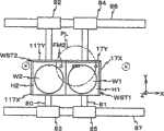
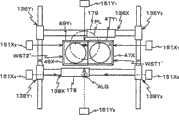
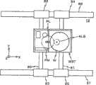
图2是表示第一实施形态的晶片载台装置的俯视图。Fig. 2 is a plan view showing the wafer stage device according to the first embodiment.
图3是表示图2的晶片载台WST1的立体图。FIG. 3 is a perspective view showing wafer stage WST1 of FIG. 2 .
图4是表示液体供排机构的概略俯视图。Fig. 4 is a schematic plan view showing a liquid supply and discharge mechanism.
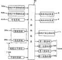
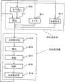
图5是表示第一实施形态的曝光装置的控制系统主要构成的方块图。Fig. 5 is a block diagram showing the main configuration of the control system of the exposure apparatus according to the first embodiment.
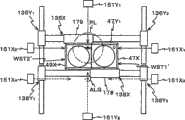
图6是用以说明并行处理动作的两个晶片载台的驱动方法的图(其1)。FIG. 6 is a diagram (Part 1) for explaining a method of driving two wafer stages in parallel processing operations.
图7是用以说明并行处理动作的两个晶片载台的驱动方法的图(其2)。FIG. 7 is a diagram (Part 2 ) for explaining a method of driving two wafer stages in a parallel processing operation.
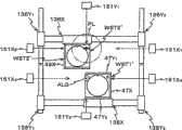
图8是用以说明并行处理动作的两个晶片载台的驱动方法的图(其3)。FIG. 8 is a diagram (part 3 ) for explaining a method of driving two wafer stages in a parallel processing operation.
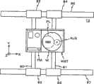
图9是用以说明并行处理动作的两个晶片载台的驱动方法的图(其4)。FIG. 9 is a diagram (part 4 ) for explaining a method of driving two wafer stages in a parallel processing operation.
图10是表示弹性密封构件的图。Fig. 10 is a diagram showing an elastic sealing member.
图11是表示第二实施形态的曝光装置的控制系统主要构成的方块图。Fig. 11 is a block diagram showing a main configuration of a control system of an exposure apparatus according to a second embodiment.
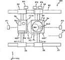
图12是表示第二实施形态的晶片载台装置的俯视图。Fig. 12 is a plan view showing a wafer stage device according to a second embodiment.
图13A是用以说明第二实施形态的并行处理动作的两个晶片载台的驱动方法的图(其1)。13A is a diagram (Part 1) for explaining a method of driving two wafer stages in a parallel processing operation according to the second embodiment.
图13B是用以说明第二实施形态的并行处理动作的两个晶片载台的驱动方法的图(其1)。Fig. 13B is a diagram (Part 1) for explaining a method of driving two wafer stages in a parallel processing operation according to the second embodiment.
图14A是用以说明第二实施形态的并行处理动作的两个晶片载台的驱动方法的图(其2)。Fig. 14A is a diagram (Part 2) for explaining a method of driving two wafer stages in a parallel processing operation according to the second embodiment.
图14B是用以说明第二实施形态的并行处理动作的两个晶片载台的驱动方法的图(其2)。Fig. 14B is a diagram (Part 2) for explaining a method of driving two wafer stages in a parallel processing operation according to the second embodiment.
图15A是用以说明第二实施形态的并行处理动作的两个晶片载台的驱动方法的图(其3)。Fig. 15A is a diagram (Part 3) for explaining a method of driving two wafer stages in a parallel processing operation according to the second embodiment.
图15B是用以说明第二实施形态的并行处理动作的两个晶片载台的驱动方法的图(其3)。Fig. 15B is a diagram (Part 3) for explaining the driving method of two wafer stages in the parallel processing operation of the second embodiment.
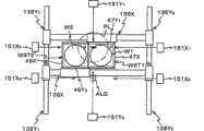
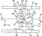
图16是表示第三实施形态的晶片载台装置的俯视图。Fig. 16 is a plan view showing a wafer stage device according to a third embodiment.
图17A是用以说明第三实施形态的并行处理动作的晶片载台与测量载台的驱动方法的图(其1)。17A is a diagram (Part 1) for explaining a method of driving a wafer stage and a measurement stage in a parallel processing operation according to the third embodiment.
图17B是用以说明第三实施形态的并行处理动作的晶片载台与测量载台的驱动方法的图(其1)。Fig. 17B is a diagram (Part 1) for explaining the method of driving the wafer stage and the measurement stage in the parallel processing operation according to the third embodiment.
图18A是用以说明第三实施形态的并行处理动作的晶片载台与测量载台的驱动方法的图(其2)。Fig. 18A is a diagram (part 2) for explaining the method of driving the wafer stage and the measurement stage in the parallel processing operation according to the third embodiment.
图18B是用以说明第三实施形态的并行处理动作的晶片载台与测量载台的驱动方法的图(其2)。18B is a diagram (Part 2) for explaining the method of driving the wafer stage and the measurement stage in the parallel processing operation of the third embodiment.
图19A是用以说明抑制构件的变形例的图。FIG. 19A is a diagram for explaining a modified example of the restraining member.
图19B是用以说明抑制构件的变形例的图。FIG. 19B is a diagram for explaining a modified example of the suppressing member.
图19C是用以说明抑制构件的变形例的图。FIG. 19C is a diagram for explaining a modified example of the suppression member.
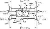
图20是表示第四实施形态的晶片载台装置的俯视图。Fig. 20 is a plan view showing a wafer stage device according to a fourth embodiment.
图21是表示晶片载台与测量载台近接状态的图。Fig. 21 is a diagram showing a state in which a wafer stage and a measurement stage approach each other.
图22A是用以说明第四实施形态的并行处理动作的晶片载台与测量载台的驱动方法的图(其1)。Fig. 22A is a diagram (Part 1) for explaining the method of driving the wafer stage and the measurement stage in the parallel processing operation according to the fourth embodiment.
图22B是用以说明第四实施形态的并行处理动作的晶片载台与测量载台的驱动方法的图(其1)。Fig. 22B is a diagram (Part 1) for explaining the method of driving the wafer stage and the measurement stage in the parallel processing operation according to the fourth embodiment.
图23A是用以说明第四实施形态的并行处理动作的晶片载台与测量载台的驱动方法的图(其2)。Fig. 23A is a diagram (Part 2) for explaining the method of driving the wafer stage and the measurement stage in the parallel processing operation according to the fourth embodiment.
图23B是用以说明第四实施形态的并行处理动作的晶片载台与测量载台的驱动方法的图(其2)。Fig. 23B is a diagram (Part 2) for explaining the method of driving the wafer stage and the measurement stage in the parallel processing operation according to the fourth embodiment.
图24是用以说明第四实施形态的变形例的图(其1)。Fig. 24 is a diagram (No. 1) for explaining a modified example of the fourth embodiment.
图25A是用以说明第四实施形态的变形例的图(其2)。Fig. 25A is a diagram (No. 2) for explaining a modified example of the fourth embodiment.
图25B是用以说明第四实施形态的变形例的图(其2)。Fig. 25B is a diagram (No. 2) for explaining a modified example of the fourth embodiment.
图26是用以说明本发明的元件制造方法的流程图。Fig. 26 is a flow chart for explaining the device manufacturing method of the present invention.
图27是表示图26的步骤204的具体例的流程图。FIG. 27 is a flowchart showing a specific example of step 204 in FIG. 26 .
主要元件符号说明:Description of main component symbols:
5:液体供应装置5: Liquid supply device
6:液体回收装置6: Liquid recovery device
10:照明系统10: Lighting system
11:标线片载台驱动部11: Reticle stage drive unit
12:基盘12: base plate
15:移动镜15: Moving Mirror
16、18:X轴干涉计16, 18: X-axis interferometer
17X、117X:X移动镜17X, 117X: X moving mirror
17Y、117Y:Y移动镜17Y, 117Y: Y moving mirror
20:主控制装置20: Master control device
21、22、27、28:供应管21, 22, 27, 28: supply pipe
21a、21b、21c、22a、22b、22c、27a、28a:供应嘴21a, 21b, 21c, 22a, 22b, 22c, 27a, 28a: supply nozzle
23、24、29、30:回收管23, 24, 29, 30: Recovery tube
23a、23b、24a、24b、29a、29b、30a、30b:回收嘴23a, 23b, 24a, 24b, 29a, 29b, 30a, 30b: Recovery nozzle
32:液体供排系统32: Liquid supply and drainage system
40:镜筒40: lens barrel
44、46、48:Y轴干涉计44, 46, 48: Y-axis interferometer
47X、49X:X移动镜47X, 49X: X moving mirror
47Y1、47Y2、49Y1、49Y2:Y移动镜47Y1 , 47Y2 , 49Y1 , 49Y2 : Y moving mirror
49、49’:槽49, 49': Groove
50、50’、50”:晶片载台装置50, 50’, 50”: wafer stage device
70:本体部70: Main body
72a~72d:辅助板72a~72d: auxiliary board
80~87:晶片载台驱动部80~87: Wafer stage drive unit
80、81、136Y1、136Y2、138Y1、138Y2、186、187、188、189:Y轴线性导件(Y轴线性发动机)80, 81, 136Y1 , 136Y2 , 138Y1 , 138Y2 , 186, 187, 188, 189: Y-axis linear guide (Y-axis linear engine)
82、83、84、85、86、87、136X、138X、180、181:X轴线性导件(X轴线性发动机)82, 83, 84, 85, 86, 87, 136X, 138X, 180, 181: X-axis linear guide (X-axis linear engine)
90a:照射系统90a: Irradiation system
90b:受光系统90b: Light receiving system
91:前端透镜91: front lens
93、93’、93”:密封构件、弹性密封构件93, 93’, 93”: sealing member, elastic sealing member
94:平板94: tablet
95:泼水被膜95: water splash film
100:曝光装置100: exposure device
111a:凸缘部111a: flange part
111b:段部111b: section
111c:突部111c: protrusion
116:标线片干涉计116: Reticle interferometer
118、118A:干涉计系统118, 118A: Interferometer system
124、124A:晶片载台驱动部124, 124A: wafer stage drive unit
151X1、151X2、151X3、151X4、151Y1、151Y2:干涉计151X1 , 151X2 , 151X3 , 151X4 , 151Y1 , 151Y2 : Interferometer
171:第一驱动部171: First drive unit
172:第二驱动部172: Second drive unit
178、179:X可动件178, 179: X movable parts
182、183、184、185:Y可动件182, 183, 184, 185: Y movable parts
195:第一连接机构195: First connection mechanism
196:第二连接机构196: Second connection mechanism
ALG1、ALG2:对准系统ALG1, ALG2: alignment system
B11X、B12X、B11Y、B12Y、B13Y:测轴B11X, B12X, B11Y, B12Y, B13Y: measuring axis
AX:光轴AX: optical axis
FM1、FM2:基准标记板FM1, FM2: Fiducial Marker Plate
H1、H2:晶片保持具H1, H2: wafer holder
IA:曝光区域IA: Exposure Area
IF1、IF5、IF6:X轴干涉计IF1, IF5, IF6: X-axis interferometer
IF2、IF3、IF4:Y轴干涉计IF2, IF3, IF4: Y-axis interferometer
IL:照明用光(曝光用光)IL: Light for illumination (light for exposure)
Lq:液体Lq: liquid
MST、MST’:测量载台MST, MST’: measurement stage
PL:投影光学系统PL: projection optics
PU:投影单元PU: projection unit
R:标线片R: Reticle
RAa、Rab:标线片对准检测系统RAa, Rab: Reticle Alignment Detection System
RST:标线片载台RST: Reticle Stage
Sb、Sc、Se:端面Sb, Sc, Se: end face
W1、W2:晶片W1, W2: chip
WST1、WST2、WST1’、WST2’、WST1”、WST2”:晶片载台WST1, WST2, WST1’, WST2’, WST1”, WST2”: wafer stage
具体实施方式Detailed ways
第一实施形态:The first form of implementation:
以下,依图1~图10说明本发明的第一实施形态。Hereinafter, a first embodiment of the present invention will be described with reference to FIGS. 1 to 10 .
在图1,表示第一实施形态的曝光装置100的概略构成。此曝光装置100,是步进扫描(step and scan)方式的投影曝光装置,即所谓扫描步进机(也称为扫描机)。此曝光装置100具备:照明系统10;标线片载台RST,用以保持当作掩膜使用的标线片R;投影单元PU;晶片载台装置50,具有当作第一、第二载台使用的晶片载台WST1、WST2;偏轴对准(off axisalignment)系统ALG1、ALG2,当作第一、第二标记检测系统;及这些构件的控制系统。在晶片载台WST1、WST2上,载置作为基板的晶片。在图1,在晶片载台WST1上载置晶片W1,在晶片载台WST2上载置晶片W2。FIG. 1 shows a schematic configuration of an
前述照明系统10,例如日本特开2001-313250号公报及对应于此的美国专利申请公开第2003/0025890号说明书所揭示,包含:光源、照度均匀化光学系统(含有光学积分器)、分束器、中继透镜、可变ND滤光片、标线片遮帘等(均未图标)。此照明系统10,将标线片遮帘所限制的标线片R上的狭缝状照明区域,通过照明用光(曝光用光)IL(作为能量光束)以大致均匀的照度照明。在此,照明用光IL,作为一例,使用ArF准分子激光(波长193nm)。又,光学积分器,能使用复眼透镜、杆式积分器(内面反射型积分器)或绕射光学元件等。其它,照明系统10,也可采用例如日本特开平6-349701号公报及对应于此的美国专利第5,534,970号等所揭示的构成。在本案所指定的指定国(或所选择的选择国)的国内法令所允许的范围,援用上述各公报及对应于此的美国专利申请公开说明书或美国专利的揭示,作为本说明书的记载的一部分。The
在前述标线片载台RST上,将形成电路图案等于其图案面(在图1是下面)的标线片R,例如通过真空吸附固定。标线片载台RST,例如通过包含线性发动机等的标线片载台驱动部11(在图1未图标,参照图5),能在垂直于照明系统10的光轴(一致于后述的投影光学系统PL的光轴AX)的XY平面内微驱动,并且能朝既定的扫描方向(在此,设为与图1纸面正交方向的Y轴方向)以所指定的扫描速度驱动。On the reticle stage RST, the reticle R on which the circuit pattern is formed equal to the pattern surface (lower side in FIG. 1 ) is fixed, for example, by vacuum suction. The reticle stage RST, for example, can be driven vertically to the optical axis of the illumination system 10 (consistent with the following description) by a reticle stage drive unit 11 (not shown in FIG. 1 , see FIG. 5 ) including a linear motor or the like. The optical axis AX) of the projection optical system PL is slightly driven in the XY plane, and can be driven at a predetermined scanning speed in a predetermined scanning direction (here, the Y-axis direction perpendicular to the paper surface of FIG. 1 ).
标线片载台RST的载台移动面内的位置,是通过标线片激光干涉计(以下称为“标线片干涉计”)116,通过移动镜15,例如以0.5~1nm程度的分解能持续检测。在此,实际上,虽在标线片载台RST上设置具有正交于Y轴方向的反射面的Y移动镜与具有正交于X轴方向的反射面的X移动镜,对应这些移动镜设置标线片Y干涉计与标线片X干涉计,但在图1以移动镜15、标线片干涉计116为代表这些元件来表示。又,也可例如将标线片载台RST的端面镜面加工来形成反射面(相当于上述的X移动镜、Y移动镜的反射面)。又,替代朝X轴方向延伸的反射面(使用于标线片载台RST的扫描方向(在本实施形态是Y轴方向)的位置检测),也可使用至少一个直角反射镜(corner cube mirror)(例如retroreflector)。在此,标线片Y干涉计与标线片X干涉计的一方,例如标线片Y干涉计,是具有2轴测长轴的2轴干涉计,根据此标线片Y干涉计的测量值,除了标线片载台RST的Y位置外,也能测量Z轴周围的旋转方向(θz方向)的旋转。The position in the stage movement plane of the reticle stage RST is determined by the reticle laser interferometer (hereinafter referred to as "reticle interferometer") 116 and the moving
标线片干涉计116的测量值,送至主控制装置20(在图1未图标,参照图5),主控制装置20,根据此标线片干涉计116的测量值算出标线片载台RST的X、Y、θz方向的位置,并且根据此算出结果控制标线片载台驱动部11,藉此来控制标线片载台RST的位置(及速度)。The measured value of the
在标线片R的上方,将使用曝光波长的光的TTR(Through The Reticle)对准系统所构成的一对标线片对准检测系统RAa、RAb沿X轴方向隔既定距离设置,用以通过投影光学系统PL将标线片R上的标线片标记与所对应的基准标记板上的基准标记同时观察。此等标线片对准检测系统RAa、RAb,使用例如与日本特开平7-176468号公报及对应于此的美国专利第5,646,413号等所揭示的同样的构成。在本案所指定的指定国(或所选择的选择国)的国内法令所允许的范围,援用上述公报及对应于此的美国专利的揭示,作为本说明书的记载的一部分。Above the reticle R, a pair of reticle alignment detection systems RAa and RAb composed of a TTR (Through The Reticle) alignment system using light at the exposure wavelength are set at a predetermined distance along the X-axis direction for The reticle marks on the reticle R and the fiducial marks on the corresponding fiducial mark plate are simultaneously observed by the projection optical system PL. These reticle alignment detection systems RAa and RAb use, for example, the same configuration as those disclosed in JP-A-7-176468 and US Pat. No. 5,646,413 corresponding thereto. To the extent permitted by the domestic laws and regulations of the designated country (or selected country) designated in this case, the disclosures of the above-mentioned publications and the corresponding US patents are cited as part of the description of this specification.
投影单元PU,配置于图1的标线片载台RST的下方。投影单元PU,包含:镜筒40;及投影光学系统PL,由在该镜筒40内以既定的位置关系保持的多个光学元件组成。投影光学系统PL,例如使用由具有Z轴方向的共同光轴AX的多个透镜(透镜元件)所构成的折射光学系统。此投影光学系统PL,例如在两侧远心具有既定的投影倍率(例如1/4倍、1/5倍或1/8倍)。因此,若以来自照明系统10的照明用光IL使标线片R的照明区域照明,由通过此标线片R的照明用光IL,通过投影单元PU(投影光学系统PL),将该照明区域内的标线片R的电路图案的缩小像(电路图案的一部分的缩小像)形成于在表面涂布有光刻胶(感光剂)的晶片上。Projection unit PU is disposed below reticle stage RST in FIG. 1 . Projection unit PU includes:
又,在本实施形态的曝光装置100,如后述由于是进行适用液浸法的曝光,故伴随数值孔径NA实质上增大,标线片侧的孔径也变大。因此,在仅以透镜构成的折射光学系统,要满足珀兹伐(Petzval)条件变成困难,而有使投影光学系统大型化的趋势。为了要避免这种投影光学系统的大型化,也可使用包含反射镜与透镜所构成的反射折射系统(catadioptric系统)。In addition, in the
又,本实施形态,在构成投影光学系统PL的最像面侧(晶片侧)的透镜(以下,称为“前端透镜”)91与晶片载台WST1或WST2上的晶片之间(或前端透镜91与晶片载台WST1或WST2之间),设置用以局部供应液体的液体供排系统32。在图1,表示构成此液体供排单元之嘴,来代表液体供排系统32。又,对液体供排系统32的构成等,将予后述。In addition, in this embodiment, between the lens (hereinafter referred to as "tip lens") 91 on the most image plane side (wafer side) constituting projection optical system PL and the wafer on wafer stage WST1 or WST2 (or the
前述晶片载台装置50具备:基盘12;晶片载台WST1、WST2,配置于该基盘12上面的上方;干涉计系统118(参照图5),包含用来测量所述晶片载台WST1、WST2的位置的干涉计的位置测量装置;及晶片载台驱动部124(参照图5),用以驱动晶片载台WST1、WST2。The aforementioned
在晶片载台WST1、WST2的底面,将未图标的非接触轴承,例如真空预压型空气静压轴承(以下,称为「气垫」)设置于多个位置,由从所述气垫朝基盘12上面所喷出的加压空气的静压,在基盘12上面的上方将晶片载台WST1、WST2通过数μm程度的间隙非接触地浮起支撑。又,晶片载台WST1、WST2,由晶片载台驱动部124,独立于X轴方向(图1纸面内的左右方向)及Y轴方向(与图1纸面正交的方向)能沿二维方向驱动。On the bottom surfaces of wafer stages WST1 and WST2, unillustrated non-contact bearings, such as vacuum preloaded aerostatic bearings (hereinafter referred to as "air cushions"), are provided at multiple positions, and The static pressure of the pressurized air blown from the upper surface floats and supports wafer stages WST1 , WST2 above the upper surface of
在基盘12上,如图2的俯视图所示,将一对X轴线性导件(朝X轴方向延伸的X固定件)86、87沿Y轴方向隔既定间隔配置。这些X轴线性导件86、87,例如由内设永久磁铁群组(沿X轴方向以既定间隔且交替配置的N极磁铁与S极磁铁的多组所构成)的磁极单元来构成。在这些X轴线性导件86、87上方,设置各两个滑件82、84及83、85,形成将所对应的X轴线性导件86、87从上方包围的状态且非接触。即,合计四个滑件82、84、83、85,具有截面倒U字形的形状,形成将X轴线性导件86、87从上方及侧方包围,对所对应的X轴线性导件86、87分别通过未图标的气垫例如以数μm程度的间隙浮起支撑。各滑件82、84、83、85,例如由分别内设沿X轴方向以既定间隔配置的电枢线圈的电枢单元来构成。即,在本实施形态,由电枢单元所构成的滑件82、84与磁极单元所构成的X轴线性导件86,分别构成动圈型的X轴线性发动机。同样地,由滑件83、85与X轴线性导件87,分别构成动圈(moving coil)型的X轴线性发动机。以下,对上述四个各X轴线性发动机,使用与构成各可动件的滑件82、84、83、85相同的符号,称为X轴线性发动机82、X轴线性发动机84、X轴线性发动机83、X轴线性发动机85。On the
上述四个X轴线性发动机中,构成两个X轴线性发动机82、83的滑件,分别固定于Y轴线性导件80(当作朝Y轴方向延伸的Y固定件)的长边方向的一端与另一端。又,构成另外的两个X轴线性发动机84、85的滑件,固定于Y轴线性导件81(当作朝Y轴方向延伸的Y固定件)的一端与另一端。因此,Y轴线性导件80、81,由各一对的X轴线性发动机82、83、84、85,使其沿X轴分别驱动。Among the above-mentioned four X-axis linear motors, the sliders constituting the two X-axis
前述各Y轴线性导件80、81,例如由分别内设沿Y轴方向以既定间隔配置的电枢线圈的电枢单元来构成。The aforementioned Y-axis
一Y轴线性导件81,以插入状态设置于形成在晶片载台WST1的开口。在此晶片载台WST1的上述开口的内部,设置具有永久磁铁群组(例如沿Y轴方向以既定间隔且交替配置的N极磁铁与S极磁铁的多组所构成)的磁极单元。由此磁极单元与Y轴线性导件81,构成将晶片载台WST1沿Y轴方向驱动的动磁型的Y轴线性发动机。同样地,另一Y轴线性导件80,以插入状态设置于形成在晶片载台WST2的开口。在此晶片载台WST2的上述开口的内部,设置与晶片载台WST1侧同样的磁极单元。由此磁极单元与Y轴线性导件80,构成将晶片载台WST2沿Y轴方向驱动的动磁(movingmagnet)型的Y轴线性发动机。在以下,对这些Y轴线性发动机,使用与构成各固定件的线性导件81、80相同的符号,称为Y轴线性发动机81、Y轴线性发动机80。A Y-axis
在本实施形态,包含X轴线性发动机82~85及Y轴线性发动机80、81,来构成图5所示的晶片载台驱动部124。构成此晶片载台驱动部124的上述各线性发动机,则由图5所示的主控制装置20控制。In this embodiment, the wafer
又,由使一对X轴线性发动机84、85(或82、83)分别所产生的推力稍微不同,能控制晶片载台WST1(或WST2)的偏摇(yawing)。Also, by making the thrusts generated by the pair of X-axis
在本实施形态,各晶片载台WST1、WST2,虽以单一的载台图标,但实际上,具备:载台本体,由Y轴线性发动机81、80分别驱动;晶片台,通过Z·调平驱动机构(例如音圈发动机)载置于该载台本体的上部,对载台本体相对地沿Z轴方向及X轴周围的旋转方向(θx方向)、Y轴周围的旋转方向(θy方向)微驱动。In this embodiment, although each wafer stage WST1, WST2 is shown as a single stage, in fact, it is equipped with: the stage body is driven by the Y-axis
在前述晶片载台WST1上(晶片台上),如图1所示,设置晶片保持具H1,由真空吸附等保持晶片W1。晶片保持具H1,如图3的立体图所示,具备:本体部70,俯视(从上方观察)大致呈正方形;四片辅助板72a~72d,以从上方重叠于本体部70的方式配置于晶片W1的载置区域周围。这些辅助板72a~72d的表面,形成与晶片W1的表面大致相同的高度。又,辅助板72a~72d,也可由一个构件构成。又,若能在投影光学系统PL的像面侧保持液体Lq,也可在晶片表面与辅助板表面之间有段差。On the aforementioned wafer stage WST1 (wafer stage), as shown in FIG. 1, a wafer holder H1 is provided, and the wafer W1 is held by vacuum suction or the like. The wafer holder H1, as shown in a perspective view of FIG. Around the mounting area of W1. The surfaces of these auxiliary plates 72a to 72d are formed at approximately the same height as the surface of the wafer W1. Also, the auxiliary plates 72a to 72d may be constituted by one member. Also, if the liquid Lq can be held on the image plane side of the projection optical system PL, there may be a level difference between the wafer surface and the auxiliary plate surface.
在晶片载台WST1的上面,将X移动镜17X(在X轴方向的一端(+X侧端)具有与X轴正交的反射面)朝Y轴方向延设,将Y移动镜17Y(在Y轴方向的一端(+Y侧端)具有与Y轴正交的反射面)朝X轴方向延设。对这些移动镜17X、17Y的各反射面,如图2所示,将来自构成后述的干涉计系统118(参照图5)的干涉计的干涉计光束(测长光束)投射,由以各干涉计接收该反射光,将从各移动镜反射面的基准位置(一般是在投影单元PU侧面,或对准系统ALG1的侧面配置固定反射镜,以此为基准面)的位移测量,藉此,测量晶片载台WST1的二维位置。较佳者为移动镜17X、17Y的上面也设为与晶片W1大致相同的高度。On the upper surface of wafer stage WST1, an X
在此,如图3所示,在各辅助板72a~72d与晶片W1之间,虽存在间隙D,但间隙D的尺寸,是以成为0.1~1mm的方式设定。又,在晶片W1,虽在其一部分存在缺口(V字形的缺口),但因此缺口的尺寸也是仅1mm程度,故省略图标。Here, as shown in FIG. 3 , there is a gap D between each of the auxiliary plates 72 a to 72 d and the wafer W1 , but the size of the gap D is set to be 0.1 to 1 mm. In addition, although there is a notch (V-shaped notch) in part of the wafer W1, the size of the notch is also only about 1 mm, so the illustration is omitted.
又,辅助板72a,在其一部分形成圆形开口,在其开口内,嵌入基准标记板FM1。基准标记板FM1,是使其表面与辅助板72a为大致同一面。在基准标记板FM1的表面,形成至少一对标线片对准用的第一基准标记,及如后述以对准系统ALG1所检测的第二基准标记(均未图标)等。Moreover, the auxiliary plate 72a has a circular opening formed in a part thereof, and the fiducial mark plate FM1 is fitted into the opening. The fiducial mark plate FM1 has a surface substantially flush with the auxiliary plate 72a. On the surface of fiducial mark plate FM1, at least a pair of first fiducial marks for reticle alignment, second fiducial marks (both not shown) and the like which are detected by alignment system ALG1 as described later are formed.
在前述晶片载台WST2上(晶片台上),如图1所示,设置晶片保持具H2,由真空吸附等保持晶片W2。此晶片保持具H2,是与前述的晶片保持具H1构成同样。因此,在形成于构成此晶片保持具H2的一个辅助板的一部分的圆形开口内,嵌入基准标记板FM2(在图1未图标,参照图2)。On the aforementioned wafer stage WST2 (wafer stage), as shown in FIG. 1, a wafer holder H2 is provided, and the wafer W2 is held by vacuum suction or the like. This wafer holder H2 has the same configuration as the aforementioned wafer holder H1. Therefore, a fiducial mark plate FM2 (not shown in FIG. 1 , see FIG. 2 ) is fitted into a circular opening formed in a part of one auxiliary plate constituting this wafer holder H2 .
又,在晶片载台WST2的上面,将X移动镜117X(在X轴方向的一端(-X侧端)具有与X轴正交的反射面)朝Y轴方向延设,将Y移动镜117Y(在Y轴方向的一端(+Y侧端)具有与Y轴正交的反射面)朝X轴方向延设。对这些移动镜117X、117Y的各反射面,如图2所示,将来自构成后述的干涉计系统118的干涉计的干涉计光束(测长光束)投射,由以各干涉计接收该反射光,将来自各移动镜反射面的基准位置的位移测量,藉此测量晶片载台WST2的二维位置。Further, on the upper surface of wafer stage WST2, an X
又,例如,可将晶片载台WST1、WST2的端面作镜面加工来形成移动镜(相当于前述的移动镜17X、17Y、117X、117Y的反射面)。Also, for example, the end surfaces of wafer stages WST1, WST2 may be mirror-finished to form moving mirrors (corresponding to the reflection surfaces of moving
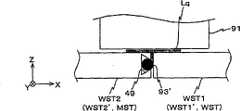
又,在晶片载台WST1、WST2彼此对向侧的面,例如在晶片载台WST1的-X侧面,在其全面,如图10所示,贴附密封构件93。此密封构件93,例如使用由含氟橡胶等所构成的弹性密封构件。Further, on the surfaces of wafer stages WST1 and WST2 facing each other, for example, on the -X side of wafer stage WST1, a sealing
又,替代晶片载台WST1的-X侧面,也可将密封构件93贴附于晶片载台WST2的+X侧面,也可将密封构件93贴附于晶片载台WST1的-X侧面与晶片载台WST2的+X侧面双方。Also, instead of the -X side surface of wafer stage WST1, the sealing
回到图1,在分别隔相同距离于投影单元PU的+X侧、-X侧的位置,分别配置前述的偏轴对准系统(以下,略述为“对准系统”)ALG1、ALG2。这些对准系统ALG1、ALG2,实际上,是装设于用以保持投影单元PU的保持构件。这些对准系统ALG1、ALG2,例如使用影像处理方式的FIA(FieldImage Alignment)系统的感测器,该影像处理方式,是将对象标记的像(将不使晶片上的光刻胶感光的宽频(broad band)的检测光束照射于对象标记,由来自该对象标记的反射光结像于受光面)与未图标的指针(设置于对准系统ALG1、ALG2内的指针板上的指针图案)的像使用摄影元件(CCD等)来摄影后,将这些摄影信号输出。又,对准系统ALG1、ALG2,不限于FIA系统,将相干(coherent)的检测用光照射于对象标记,检测从该对象标记所产生的散射光或绕射光,或使从该对象标记所产生的两个绕射光(例如同次数的绕射光,或绕射于同方向的绕射光)干涉来检测的对准感测器,单独或适当组合使用当然可能。Referring back to FIG. 1 , the above-mentioned off-axis alignment systems (hereinafter, abbreviated as “alignment systems”) ALG1 and ALG2 are respectively disposed at positions on the +X side and −X side of the projection unit PU at the same distance. These alignment systems ALG1 and ALG2 are actually installed on a holding member for holding projection unit PU. These alignment systems ALG1 and ALG2 are, for example, sensors of the FIA (Field Image Alignment) system using an image processing method, which is an image of an object mark (a broadband ( The detection beam of the broad band) is irradiated on the object mark, and the reflected light from the object mark is imaged on the light receiving surface) and the image of the uniconted pointer (the pointer pattern set on the pointer plate in the alignment system ALG1, ALG2) After imaging is performed using an imaging element (CCD, etc.), these imaging signals are output. In addition, the alignment systems ALG1 and ALG2 are not limited to the FIA system, and irradiate the target mark with coherent detection light, detect scattered light or diffracted light generated from the target mark, or make the light generated from the target mark Two diffracted lights (for example, diffracted lights of the same order, or diffracted lights in the same direction) interfere to detect the alignment sensor, and it is of course possible to use them alone or in combination.
在本实施形态,对准系统ALG1,是使用于形成在晶片载台WST1上的晶片W1的对准标记及形成在基准标记板FM1上的基准标记的位置测量等。又,对准系统ALG2,是使用于形成在晶片载台WST2上的晶片W2的对准标记及形成在基准标记板FM2上的基准标记的位置测量等。In the present embodiment, alignment system ALG1 is used for position measurement of alignment marks formed on wafer W1 on wafer stage WST1 and fiducial marks formed on fiducial mark plate FM1 . Also, alignment system ALG2 is used for position measurement of alignment marks formed on wafer W2 on wafer stage WST2 and fiducial marks formed on fiducial mark plate FM2 , and the like.
来自这些对准系统ALG1、ALG2的资料,如图5所示,供应至主控制装置20。Data from these alignment systems ALG1 , ALG2 are supplied to the
其次,参照图2说明干涉计系统118的构成等。如图2所示,干涉计系统118,具有:三个Y轴干涉计46、48、44,分别具有测轴BI2Y、BI3Y、BI1Y,平行于通过投影光学系统PL的投影中心(光轴AX)、对准系统ALG1、ALG2的各检测中心的Y轴;及两个X轴干涉计16、18,分别具有测轴BI1X、BI2X,平行于连结投影光学系统PL的投影中心(光轴AX)及对准系统ALG1、ALG2的检测中心的X轴。Next, the configuration and the like of the
在此,当晶片载台WST1位于投影光学系统PL的光轴正下方的位置附近的区域(第一区域),对该晶片载台WST1上的晶片进行曝光时,由X轴干涉计18、Y轴干涉计46来管理晶片载台WST1的位置。以下,将由此X轴干涉计18、Y轴干涉计46各测长轴所规定的坐标系统称为第一曝光坐标系统。Here, when wafer stage WST1 is located in a region (first region) near the position immediately below the optical axis of projection optical system PL, and the wafer on wafer stage WST1 is exposed,
又,晶片载台WST2当投影光学系统PL位于第一区域,对该晶片载台WST2上的晶片进行曝光时,由X轴干涉计16、Y轴干涉计46来管理晶片载台WST2的位置。以下,将由此X轴干涉计16、Y轴干涉计46各别的测长轴所规定的坐标系统称为第二曝光坐标系统。In addition, when wafer stage WST2 is located in the first area and projection optical system PL is located in the first area to expose the wafer on wafer stage WST2, the position of wafer stage WST2 is controlled by
又,当晶片载台WST1,位于对准系统ALG1的检测中心正下方的位置附近的区域(第二区域),要进行形成于其晶片载台WST1上的晶片的对准标记的检测时,例如要进行后述的晶片对准时,由X轴干涉计18、Y轴干涉计48来管理晶片载台WST1的位置。以下,将由此X轴干涉计18、Y轴干涉计48各测长轴所规定的坐标系统称为第一对准坐标系统。Also, when wafer stage WST1 is located in a region (second region) near the position immediately below the detection center of alignment system ALG1, and the alignment mark of the wafer formed on the wafer stage WST1 is to be detected, for example The position of wafer stage WST1 is managed by
又,当晶片载台WST2,位于对准系统ALG2的检测中心正下方的位置附近的区域(第三区域),要进行形成于其晶片载台WST2上的晶片的对准标记的检测时,例如要进行后述的晶片对准时,由X轴干涉计16、Y轴干涉计44来管理晶片载台WST2的位置。以下,将由此X轴干涉计16、Y轴干涉计44各别的测长轴所规定的坐标系统称为第二对准坐标系统。In addition, when the wafer stage WST2 is located in the region (third region) near the position immediately below the detection center of the alignment system ALG2, and the alignment mark of the wafer formed on the wafer stage WST2 is to be detected, for example The position of wafer stage WST2 is controlled by
从上述的说明得知,在本实施形态,来自X轴干涉计18、16的干涉计光束,在晶片载台WST1、WST2的移动范围的全域持续分别照射于晶片载台WST1、WST2的移动镜17X、117X。因此,对X轴方向,使用投影光学系统PL曝光时,即使使用对准系统ALG1、ALG2时等任何情形,晶片载台WST1、WST2的位置,则由X轴干涉计18、16来管理。这些X轴干涉计18、16,是具有相对于Y轴方向及Z轴方向离开的至少三支光轴的多轴干涉计,各光轴的输出值能独立测量。因此,这些X轴干涉计18、16,除了晶片载台WST1、WST2的X轴方向的位置测量以外,也能测量Y轴周围的旋转量(横摇量(rolling))及Z轴周围的旋转量(偏摇量)。As can be seen from the above description, in this embodiment, the interferometer beams from the
又,上述Y轴干涉计46、48、44,例如是具有相对于Z轴方向离开的各二支光轴的二轴干涉计,各光轴的输出值能独立测量。因此,这些Y轴干涉计46、48、44,除了晶片载台WST1、WST2的Y轴方向的位置测量以外,也能测量X轴周围的旋转量(俯仰量(pitching))。In addition, the above-mentioned Y-
又,上述多轴干涉计,也可倾斜45°而设置于晶片载台WST1、WST2的反射面,对设置于将投影光学系统PL载置的架台(未图标)的反射面照射激光束,来检测相对于投影光学系统PL的光轴方向(Z轴方向)的相对位置数据。In addition, the above-mentioned multi-axis interferometer may be installed on the reflective surfaces of wafer stages WST1 and WST2 at an inclination of 45°, and the laser beam may be irradiated on the reflective surfaces provided on the gantry (not shown) on which the projection optical system PL is placed. Relative positional data with respect to the optical axis direction (Z-axis direction) of projection optical system PL is detected.
其次,依图4说明前述液体供排系统32。此液体供排系统32具备:液体供应装置5;液体回收装置6;供应管21、22、27、28,连接于液体供应装置5;及回收管23、24、29、30,连接于液体回收装置6。Next, the aforementioned liquid supply and
前述液体供应装置5包括:液体槽;加压泵;温度控制装置;及多个阀,用以控制对各供应管21、22、27、28的液体的供应、停止等。各阀,例如较佳者为使用流量控制阀,不仅液体的供应、停止,而且也能进行流量调整。前述温度控制装置,是用来将液体槽内的液体温度,调整为与收纳有例如投影单元PU等所构成的曝光装置本体的室(未图标)内的温度相同程度的温度。The aforementioned
前述供应管21,将其一端连接于液体供应装置5,将其它端分支为三个,在各分支端分别形成(或设置)由尖细嘴所构成的供应嘴21a、21b、21c。这些供应嘴21a、21b、21c的前端,位于前述的前端透镜91(参照图1)附近,沿X轴方向隔既定间隔且近接于曝光区域IA(与前述槽上的照明区域共同作用的像面上的区域)的+Y来配置。以供应嘴21a为中心,将供应嘴21b、21c配置于大致左右对称。One end of the
前述供应管22,将其一端连接于液体供应装置5,将其它端分支为三个,在各分支端分别形成(或设置)由尖细嘴构成的供应嘴22a、22b、22c。这些供应嘴22a、22b、22c的前端,位于前端透镜91附近,沿X轴方向隔既定间隔且近接于曝光区域IA的-Y来配置。在此情形,供应嘴22a、22b、22c,隔着曝光区域LA对向于供应嘴21a、21b、21c来配置。One end of the
前述供应管27,将其一端连接于液体供应装置5,将其它端形成(或设置)为由尖细嘴所构成的供应嘴27a。此供应嘴27a的前端,位于前端透镜91附近,近接于曝光区域IA的-X侧来配置。The
前述供应管28,将其一端连接于液体供应装置5,将其它端形成(或设置)为由尖细嘴所构成的供应嘴28a。此供应嘴28a的前端,位于前端透镜91附近,近接于曝光区域IA的+X侧,且隔着曝光区域IA对向于供应嘴27a来配置。The
又,不需要将用以供应液体的槽、加压泵、温度控制装置、阀等全部设于曝光装置100,至少将一部分能由设置曝光装置100的工厂等的设备来替代。In addition, it is not necessary to provide all the tanks, booster pumps, temperature control devices, valves, etc. for supplying the liquid in the
前述液体回收装置6包括:液体槽;吸引泵;及多个阀,用以控制分别通过各回收管23、24、29、30的液体的回收、停止等。各阀,较佳者为对应前述的液体供应装置5侧的阀,使用流量控制阀。The aforementioned
前述回收管23,将其一端连接于液体回收装置6,将其它端分支为二股,在各分支端分别形成(或设置)由尾宽嘴所构成的回收嘴23a、23b。在此情形,回收嘴23a、23b,是交替配置于供应嘴22a~22c之间。各回收嘴23a、23b的前端及各供应嘴22a、22b、22c的前端,大致沿着平行于X轴的同一直线上来配置。The
前述回收管24,将其一端连接于液体回收装置6,将其它端分支为二股,在各分支端分别形成(或设置)由尾宽嘴所构成的回收嘴24a、24b。在此情形,回收嘴24a、24b,是在供应嘴21a~21c之间,交替且隔着曝光区域IA分别对向于回收嘴23a、23b来配置。各回收嘴23a、23b的前端及各供应嘴21a、21b、21c的前端,大致沿着平行于X轴的同一直线上来配置。The
前述回收管29,将其一端连接于液体回收装置6,将其它端分支为二股,在各分支端分别形成(或设置)由尾宽嘴所构成的回收嘴29a、29b。这些回收嘴29a、29b,是隔着供应嘴28a配置。各回收嘴29a、29b及供应嘴28a的前端,大致沿着平行于Y轴的同一直线上来配置。The
前述回收管30,将其一端连接于液体回收装置6,将其它端分支为二股,在各分支端分别形成(或设置)由尾宽嘴所构成的回收嘴30a、30b。这些回收嘴30a、30b,是隔着供应嘴27a,且隔着曝光区域IA分别对向于回收嘴29a、29b来配置。各回收嘴30a、30b及供应嘴27a的前端,大致沿着平行于Y轴的同一直线上来配置。The above-mentioned
又,不需要将用以回收液体的槽、吸引泵、阀等全部设于曝光装置100,至少将一部分能由设置曝光装置100的工厂等的设备来替代。In addition, it is not necessary to provide all the tanks for recovering liquid, suction pumps, valves, etc. in the
在本实施形态,上述液体,是使用能通过ArF准分子激光(波长193nm)的超纯水(以下,除了特别需要时,简单称为“水”)。超纯水,能在半导体制造工厂容易大量获得,并且具有对涂布于晶片上的光刻胶(感光剂)或光学透镜等无不良影响的优点。又,超纯水对环境无不良影响,并且因杂质的含有量极低,故也能期待对晶片的表面及前端透镜91的表面的洗净作用。In this embodiment, the above-mentioned liquid is ultrapure water (hereinafter, simply referred to as "water" unless otherwise required) that can pass ArF excimer laser light (wavelength: 193 nm). Ultrapure water can be easily obtained in large quantities in semiconductor manufacturing plants, and has the advantage of not adversely affecting the photoresist (sensitizer) or optical lens coated on the wafer. In addition, ultrapure water has no adverse effect on the environment, and because the content of impurities is extremely low, it can also expect a cleaning effect on the surface of the wafer and the surface of the
对ArF准分子激光的水的折射率n,是大致1.44。在此水中,照明用光IL的波长,则使其短波长化为193nm×1/n=约134nm。The refractive index n of water for ArF excimer laser is about 1.44. In this water, the wavelength of the illumination light IL is shortened to 193 nm×1/n=approximately 134 nm.
前述液体供应装置5及液体回收装置6,分别具备控制器,各控制器,由主控制装置20来控制(参照图5)。例如,沿图4中的实线箭头A所示的方向(-Y方向)使晶片W1(或W2)移动时,液体供应装置5的控制器,依照主控制装置20的指示,以既定开度打开连接于供应管21的阀,使其它阀为全闭,通过设置于供应管21的供应嘴21a~21c朝-Y方向将水供应至前端透镜91与晶片W1(或W2)之间。又,此时,液体回收装置6的控制器,依照主控制装置20的指示,以既定开度打开连接于回收管23的阀,使其它阀为全闭,通过回收嘴23a、23b从前端透镜91与晶片W1(或W2)之间将水回收至液体回收装置6的内部。此时,主控制装置20,对液体供应装置5、液体回收装置6发出指令,使从供应嘴21a~21c朝-Y方向供应至前端透镜91与晶片W1(或W2)之间的水量,与通过回收嘴23a、23b回收的水量相等。因此,在前端透镜91与晶片W1(或W2)之间,保持一定量的水Lq(参照图1)。在此情形,保持于前端透镜91与晶片W1(或W2)之间的水Lq持续替换。The aforementioned
又,沿图4中的虚线箭头A’所示的方向(+Y方向)使晶片W1(或W2)移动时,液体供应装置5的控制器,依照主控制装置20的指示,以既定开度打开连接于供应管22的阀,使其它阀为全闭,通过设置于供应管22的供应嘴22a~22c朝+Y方向将水供应至前端透镜91与晶片W1(或W2)之间。又,此时,液体回收装置6的控制器,依照主控制装置20的指示,以既定开度打开连接于回收管24的阀,使其它阀为全闭,通过回收嘴24a、24b从前端透镜91与晶片W1(或W2)之间至液体回收装置6的内部回收水。此时,主控制装置20,对液体供应装置5、液体回收装置6发出指令,使从供应嘴22a~22c朝+Y方向供应至前端透镜91与晶片W1(或W2)之间的水量,与通过回收嘴24a、24b回收的水量相等。因此,在前端透镜91与晶片W1(或W2)之间,保持一定量的水Lq(参照图1)。在此情形,保持于前端透镜91与晶片W1(或W2)之间的水Lq持续替换。Also, when the wafer W1 (or W2) is moved in the direction (+Y direction) shown by the dotted arrow A' in FIG. The valve connected to the
如此,在本实施形态,因隔着曝光区域IA在Y轴方向一侧与另一侧,分别设置彼此成组的供应嘴群组与回收嘴群组,故即使要将晶片朝+Y方向或-Y方向的任一方移动时,在晶片W1(或W2)与前端透镜91之间使水稳定地持续填满。即,即使是正扫描及负扫描的任一情形,也能在前端透镜91与晶片之间稳定地保持水。In this way, in this embodiment, since the supply nozzle group and the recovery nozzle group are respectively provided in groups on one side and the other side of the Y-axis direction across the exposure area IA, even if the wafer is to be directed toward the +Y direction or -While moving in any one of the Y directions, the space between the wafer W1 (or W2 ) and the
又,因水会流动于晶片W1(或W2)上,故即使在晶片W1(或W2)上附着异物(包含来自光刻胶的飞散粒子)的情形,能将该异物用水冲洗。又,因供应由液体供应装置5已调整为既定温度的水,且此水是持续替换,故即使在曝光时照明用光IL照射于晶片W1(或W2)上,在晶片与流动于该晶片上的水之间进行热交换,能防止晶片表面的温度上升。又,在本实施形态,因水沿与移动晶片的方向相同方向流动,故不会使已吸收异物或热的液体滞留于前端透镜正下方的曝光区域而能将其回收。Also, since water flows on wafer W1 (or W2), even if foreign matter (including flying particles from photoresist) adheres to wafer W1 (or W2), the foreign matter can be washed away with water. In addition, since the water adjusted to a predetermined temperature by the
又,若要朝图4中实线箭头B所示的方向(+X方向)移动晶片W1(或W2)时,液体供应装置5的控制器,依照主控制装置20的指示,以既定开度打开连接于供应管27的阀,使其它阀为全闭,通过设置于供应管27的供应嘴27a朝+X方向将水供应至前端透镜91与晶片W1(或W2)之间。又,此时,液体回收装置6的控制器,依照主控制装置20的指示,以既定开度打开连接于回收管29的阀,使其它阀为全闭,通过回收嘴29a、29b将水从前端透镜91与晶片W1(或W2)之间回收至液体回收装置6的内部。此时,主控制装置20,对液体供应装置5、液体回收装置6发出指令,使从供应嘴27a供应至前端透镜91与晶片W1(或W2)之间的水量,与通过回收嘴29a、29b回收的水量相等。因此,在前端透镜91与晶片W1(或W2)之间,保持一定量的水Lq(参照图1)。在此情形,保持于前端透镜91与晶片W1(或W2)之间的水Lq持续替换。Also, if the wafer W1 (or W2) is to be moved in the direction (+X direction) shown by the solid line arrow B in FIG. The valve connected to the
又,若要朝图4中虚线箭头B’所示的方向(-X方向)移动晶片W1(或W2)时,液体供应装置5的控制器,依照主控制装置20的指示,以既定开度打开连接于供应管28的阀,使其它阀为全闭,通过设置于供应管28的供应嘴28a朝-X方向将水供应至前端透镜91与晶片W1(或W2)之间。又,此时,液体回收装置6的控制器,依照主控制装置20的指示,以既定开度打开连接于回收管30的阀,使其它阀为全闭,通过回收嘴30a、30b将水从前端透镜91与晶片W1(或W2)之间回收至液体回收装置6的内部。此时,主控制装置20,对液体供应装置5、液体回收装置6发出指令,使从供应嘴28a供应至前端透镜91与晶片W1(或W2)之间的水量,与通过回收嘴30a、309b回收的水量相等。因此,在前端透镜91与晶片W1(或W2)之间,保持一定量的水Lq(参照图1)。在此情形,保持于前端透镜91与晶片W1(或W2)之间的水Lq持续替换。Also, if the wafer W1 (or W2) is to be moved in the direction (-X direction) shown by the dotted arrow B' in FIG. The valve connected to the
藉此,与使晶片W1(或W2)朝Y轴方向移动的情形同样,即使要将晶片朝+X方向或-X方向的任一方移动时,将水稳定地填满于晶片与前端透镜91之间。因此,在所谓照射间步进时,即使其步进方向是任何方向,也能在晶片与前端透镜91之间稳定地持续保持水。Thereby, as in the case of moving the wafer W1 (or W2) in the Y-axis direction, even when the wafer is moved in either the +X direction or the −X direction, the wafer and the
又,以上,虽对在晶片与前端透镜91之间将水保持的情形说明,但如前述,因晶片表面与晶片保持具H1、H2的表面成为大致同一面,故即使晶片保持具H1(或H2)位于对应投影单元P正下方的曝光区域IA的位置的情形,与上述同样,水则保持于前端透镜91与晶片保持具H1(或H2),也即与前述的辅助板之间。又,步进时,若在晶片与前端透镜91之间能保持水的情形,也可停止水的供应与回收。Also, above, although the situation of holding water between the wafer and the
又,除了从X轴方向或Y轴方向进行水的供应及回收的嘴外,例如也可设置用以从斜方向进行水的供应及回收的嘴。In addition, instead of nozzles for supplying and recovering water from the X-axis direction or the Y-axis direction, for example, nozzles for supplying and recovering water from an oblique direction may be provided.
又,也可与晶片的移动方向无关,从供应嘴21a~21c、22a~22c、27a、28a持续供应液体Lq,从回收嘴23a、23b、24a、24b、29a、29b、30a、30b持续回收液体Lq。Also, regardless of the moving direction of the wafer, the liquid Lq may be continuously supplied from the
又,液体供排系统不限于上述图4的形态,只要能在投影光学系统PL的像面侧形成液浸区域,能适用各种形态。Also, the liquid supply and discharge system is not limited to the above-mentioned form shown in FIG. 4 , and various forms can be applied as long as a liquid immersion region can be formed on the image plane side of projection optical system PL.
本实施形态100,进一步在用以保持投影单元PU的未图标的保持构件,设置斜射入方式的多点焦点位置检测系统,是由照射系统90a(在图1未图标,参照图5)及受光系统90b(在图1未图标,参照图5)构成,与例如日本特开平6-283403号公报及对应于此的美国专利第5,448,332等所揭示的同样。照射系统90a,具有以图5的主控制装置20控制开关的光源,朝投影光学系统PL的结像面射出用以形成多数个针孔或狭缝的像的光束。此所射出的光束,通过设置于投影单元PU的镜筒的未图标的棱镜(照射系统90a内的光学系统的一部分)对光轴AX从斜方向照射于晶片表面。另一方面,在晶片表面被反射的这些光束的反射光束,以设置于投影单元PU的镜筒的未图标的另外的棱镜(受光系统90b内的光学系统的一部分)反射,由受光系统90b内的受光元件受光。In this
此焦点位置检测系统(90a、90b)的受光系统90b的输出的焦点偏移信号(散焦信号),是供应至主控制装置20。主控制装置20,在后述的扫描曝光时等,算出来自受光系统90b的焦点偏移信号(散焦信号),例如根据S曲线信号算出晶片表面的Z位置及θx、θy旋转,使所算出的晶片表面的Z位置及θx、θy旋转对所述的目标值的差变成零,即要使焦点偏移为零,由通过晶片载台驱动部124控制晶片载台WST1、WST2的Z轴方向的移动,及二维方向的倾斜(即,θx、θy方向的旋转),在照明用光IL的照射区域(与前述的照射区域共同的区域)内执行使投影光学系统PL的结像面与晶片的表面实质上一致的自动对焦(auto focus)及自动调平(auto levelling)。又,在本案所指定的指定国(或所选择的选择国)的国内法令所允许的范围,援用上述日本特开平6-283403号公报及对应的美国专利的揭示,作为本说明书的记载的一部分。The focus shift signal (defocus signal) output by the
又,焦点位置检测系统,也可通过液体检测晶片表面的位置资料,也可不通过液体检测。又,焦点位置检测系统,不限于在投影光学系统PL的像面侧检测晶片表面的位置资料,也可从投影光学系统PL离开处检测晶片表面的位置资料。In addition, the focus position detection system may also detect the position data on the surface of the wafer through liquid, or not through liquid detection. In addition, the focus position detection system is not limited to detecting the position data of the wafer surface on the image plane side of the projection optical system PL, and may detect the position data of the wafer surface from the point away from the projection optical system PL.
在图5,表示本实施形态的曝光装置100的控制系统的主要构成。此控制系统,以将装置全体综合控制的微电脑(或工作站)所构成的主控制装置20为中心来构成。FIG. 5 shows the main configuration of the control system of the
其次,说明本实施形态的曝光装置100曝光时的各部的动作。在此,如图2所示,说明在晶片载台WST1侧进行曝光的情形。Next, the operation of each part during exposure by the
此曝光动作的开始时,在主控制装置20,根据事前所进行的例如增强型总对准(EGA,Enhanced Global Alignment)等的晶片对准的结果等,边监视干涉计18、46的测量值,边控制X轴线性发动机84、85及Y轴线性发动机81,而将晶片载台WST1移动至用以晶片W1的第一照射区域的曝光用扫描开始位置(加速开始位置)。在此曝光次序,是在第一曝光坐标系统上进行晶片载台WST1的位置管理。At the start of this exposure operation, the
其次,在主控制装置20,开始相对于标线片R(标线片载台RST)与晶片W1(晶片载台WST1)的Y轴方向的相对扫描。此相对扫描时,主控制装置20,边监视前述的干涉计18、46及标线片干涉计116的测量值,边控制标线片载台驱动部11并且Y轴线性发动机81(及X轴线性发动机84、85)。Next, in
接着,当两载台RST、WST1加速至各目标扫描速度时,在主控制装置20,对未图标的光源(ArF准分子激光装置)发出指令,开始脉冲发光。然后,当两载台RST、WST1达到等速同步状态时,由来自照明系统10的照明用光IL(紫外脉冲光)使标线片R的图案区域开始照明,开始扫描曝光。虽在此扫描曝光开始之前,如上述,光源的脉冲发光已开始,但由主控制装置20,照明系统10内的可动标线片遮帘(未图标)的既定叶片同步于标线片载台RST而移动,藉此防止在扫描曝光的开始前对晶片W1进行不必要的曝光。Next, when the two stages RST and WST1 are accelerated to the respective target scanning speeds, the
然后,以照明用光IL依次照明标线片R的图案区域,由完成对图案区域全面的照明,结束晶片W1上的第一照射区域的扫描曝光。藉此,标线片R的图案通过投影光学系统PL缩小转印于晶片W1上的第一照射区域。Then, the pattern area of the reticle R is sequentially illuminated with the illumination light IL, and the scanning exposure of the first shot area on the wafer W1 is completed when the illumination of the entire pattern area is completed. Thereby, the pattern of the reticle R is reduced and transferred to the first shot area on the wafer W1 through the projection optical system PL.
在此情形,扫描曝光结束后,也由主控制装置20,使照明系统10内的可动标线片遮帘(未图标)同步于标线片载台RST而移动,藉此防止晶片W1的不必要的曝光。In this case, after the scanning exposure is finished, the
如上述,结束第一照射区域的扫描曝光后,由主控制装置20,通过X轴线性发动机84、85及Y轴线性发动机81使晶片载台WST1沿X、Y方向步进移动,移动至用以第二照射区域的曝光的加速开始位置(扫描开始位置)。此照射间步进时,主控制装置20,依干涉计18、46的测量值将晶片载台WST1的X、Y、θz方向的位置位移实时(real time)检测。并且,根据此测量结果,主控制装置20,控制晶片载台WST1的位置,使晶片载台WST1的XY位置位移成为既定状态。又,主控制装置20,根据晶片载台WST1的θz方向的资料,控制标线片载台RST(标线片微动载台)及晶片载台WST1的至少一旋转,使其晶片侧的旋转位移补偿。As mentioned above, after the scanning exposure of the first shot region is completed, the
接着,在照射间步进结束后,由主控制装置20,与上述同样,控制各部的动作,对晶片W1上的第二照射区域进行与上述同样的扫描曝光。Next, after the stepping between shots is completed, the
如上述,反复进行晶片W1上的照射区域的扫描曝光与供下次照射曝光的照射间步进动作,使标线片R的图案依序转印于晶片W1上的曝光对象的照射区域全部。As described above, the stepping operation between the scanning exposure of the shot area on wafer W1 and the irradiation for the next shot exposure is repeated, and the pattern of reticle R is sequentially transferred to all the shot areas of the exposure target on wafer W1.
又,上述的对晶片W1的步进扫描方式的曝光动作中,按照晶片W1的移动方向的变化,由主控制装置20,如前述,进行液体供排系统32的液体供应装置5及液体回收装置6的各阀的开关控制则是理所当然。因此,上述的对晶片W1的步进扫描方式的曝光动作中,在前端透镜91与晶片W1之间维持持续将一定量的水稳定地保持的状态。Moreover, in the exposure operation of the step-and-scan method to the wafer W1 described above, according to the change in the moving direction of the wafer W1, the
其次,对使用两个晶片载台WST1、WST2的并行处理动作,参照图2及图6~图9说明。又,以下的动作中,由主控制装置20,按照位于投影单元PU正下方的第一区域的晶片载台的移动方向,如前述进行液体供排系统32的液体供应装置5及液体回收装置6的各阀的开关控制,在投影光学系统PL的前端透镜91正下方持续填满水。但是,以下,为了要使说明容易了解,将关于液体供应装置5及液体回收装置6的控制的说明省略。Next, the parallel processing operation using two wafer stages WST1 and WST2 will be described with reference to FIG. 2 and FIGS. 6 to 9 . In addition, in the following operations, the
在图2表示:对晶片载台WST1上的晶片W1如前述以步进扫描方式进行曝光,与此并行,在晶片载台WST2侧,在对准系统ALG2的下方的第三区域进行对晶片W2的晶片对准的状态。2 shows that wafer W1 on wafer stage WST1 is exposed in a step-and-scan manner as described above, and in parallel with this, wafer W2 is exposed in the third area below alignment system ALG2 on the wafer stage WST2 side. The state of wafer alignment.
如上述,对晶片W1以步进扫描方式进行曝光期间,在晶片载台WST2侧,则进行如下所述的动作。As described above, while the wafer W1 is exposed by the step-and-scan method, the following operations are performed on the wafer stage WST2 side.
即,在上述的晶片对准前,在左侧装载位置,未图标的晶片搬送机构与晶片载台WST2之间进行晶片交换。在此,所谓左侧装载位置,是指设定为基准标记板FM2位于对准系统ALG2的正下方的位置而言。在此情形,在左侧装载位置,由对准系统ALG2检测基准标记板FM2上的第二基准标记以前,由主控制装置20执行Y轴干涉计44的重置(reset)。That is, before the wafer alignment described above, at the loading position on the left side, wafer exchange is performed between a wafer transfer mechanism (not shown) and wafer stage WST2. Here, the loading position on the left side refers to a position set such that fiducial mark plate FM2 is located directly below alignment system ALG2. In this case, at the left loading position, before the second fiducial mark on the fiducial mark plate FM2 is detected by the alignment system ALG2, the reset of the Y-
上述第二基准标记的检测时,主控制装置20,使用对准系统ALG2取进第二基准标记的影像,对其影像信号施加既定的处理,由解析其处理后的信号来检测以对准系统ALG2的指针中心为基准的第二基准标记的位置。又,主控制装置20,根据其第二基准标记的位置的检测结果与其检测时的干涉计16、44的测量结果,算出第二对准坐标系统上的第二基准标记的位置坐标。During the detection of the above-mentioned second fiducial mark, the
其次,主控制装置20,由边在前述第二对准坐标系统上管理晶片载台WST2的XY面内的位置,边使用对准系统ALG2来检测附设于晶片W2上的特定的多个照射区域(样本照射区域)的对准标记(样本标记)的位置资料(对对准系统ALG2的检测中心的位置资料),来求出第二对准坐标系统上的样本标记的位置资料。接着,主控制装置20,根据其检测结果与特定的照射区域的设计上的位置坐标,执行例如日本特开昭61-22249号公报及对应于此的美国专利第4,780,617号等所揭示的统计运算,来算出晶片W2上的多个照射区域的第二对准坐标系统上的位置坐标。即,如上述,进行EGA(增强型总对准)。并且,主控制装置20,由从晶片W2上的多个照射区域的第二对准坐标系统上的位置坐标将前述第二基准标记的位置坐标减算,使多个照射区域的位置坐标转换成以第二基准标记的位置为原点的位置坐标。又,在本案所指定的指定国(或所选择的选择国)的国内法令所允许的范围,援用上述公报及对应美国专利的揭示,作为本说明书的记载的一部分。Next, the
上述在两个晶片载台WST1、WST2上并行而进行的曝光次序与晶片交换/对准次序,通常,是晶片交换/对准次序最先结束。因此,已结束对准的晶片载台WST2,则在既定的待机位置呈等待状态。The exposure sequence and the wafer exchange/alignment sequence performed in parallel on the two wafer stages WST1 and WST2 are usually completed first by the wafer exchange/alignment sequence. Therefore, wafer stage WST2 whose alignment has been completed is in a waiting state at a predetermined waiting position.
并且,在晶片载台WST1侧,在对晶片W1的曝光结束的时点,主控制装置20,将晶片载台WST1、WST2朝图6所示的既定位置分别开始移动。Then, at the wafer stage WST1 side, when the exposure to the wafer W1 is completed, the
并且,将晶片载台WST1、WST2移动至图6所示的位置后,主控制装置20,则开始使晶片载台WST1与晶片载台WST2同时朝+X方向驱动的动作。又,在图6的状态,晶片载台WST1与晶片载台WST2是通过设置于晶片载台WST1的弹性密封构件93接触。Then, after wafer stages WST1 and WST2 are moved to the positions shown in FIG. 6 ,
如上述,由主控制装置20,使晶片载台WST1、WST2同时移动,在图6的状态,保持于投影单元PU的前端透镜91与晶片W1之间的水,则伴随晶片载台WST1、WST2朝+X侧移动,在晶片W1→晶片载台WST1(更具体而言是晶片保持具H1)→晶片载台WST2(更具体而言是晶片保持具H2)上依序移动。又,上述移动期间,晶片载台WST1、WST2则与图6的状态同样通过弹性密封构件93保持彼此接触的位置关系。在图7,表示:在上述移动的中途,水同时存在于晶片载台WST1、WST2(晶片保持具H1、H2)时的状态,即从晶片载台WST1上待将水交给晶片载台WST2上之前的状态。As mentioned above, wafer stages WST1 and WST2 are moved simultaneously by
从图7的状态,当进一步使晶片载台WST1、WST2朝+X方向同时驱动既定距离,则如图8所示,形成在晶片载台WST2上的包含基准标记板FM2的区域与前端透镜91之间保持水的状态。先行于此,主控制装置20,在使来自Y轴干涉计46的干涉计光束能照射于移动镜117Y的任一时点,执行Y轴干涉计46的重置。From the state of FIG. 7, when wafer stages WST1 and WST2 are further simultaneously driven for a predetermined distance in the +X direction, as shown in FIG. Keep water in between. Prior to this, the
接着,主控制装置20,朝图9所示的右侧装载位置开始晶片载台WST1的驱动。此右侧装载位置,设定为基准标记板FM1位在对准系统ALG1的正下方的位置。Next,
与朝上述右侧装载位置的晶片载台WST1的移动开始并行,主控制装置20,由一对标线片对准系统RAa、RAb(参照图1)使用照明用光IL进行基准标记板FM2上的一对第一基准标记与对应于其的标线片R上的标线片对准标记的晶片上投影像的相对位置检测。此时,基准标记板FM2上的一对第一基准标记与标线片对准标记的像的检测,是通过投影光学系统PL及水来进行。Parallel to the start of movement of wafer stage WST1 to the above-mentioned right loading position,
并且,主控制装置20,根据此所检测的相对位置资料,与对预先所求的第二基准标记的晶片W2上的各照射区域的位置资料,及既知的第一基准标记与第二基准标记的位置关系,算出标线片R的图案的投影位置(投影光学系统PL的投影中心)与晶片W2上的各照射区域的相对位置关系。并且,根据其算出结果,主控制装置20,与前述的晶片W1的情形同样,在第二曝光坐标系统上边管理晶片载台WST2的位置,边以步进扫描方式将标线片R的图案转印于晶片W2上的各照射区域。And, the
与上述晶片载台WST2侧的动作并行,晶片载台WST1侧,在右侧装载位置,与未图标的晶片搬送系统之间进行晶片交换,与晶片交换同时或在其后,由主控制装置20使用对准系统ALG1进行基准标记板FM1上的第二基准标记的检测。主控制装置20,先在此第二基准标记的检测以前执行Y轴干涉计48的重置。其后,主控制装置20,边在第一对准时坐标系统上管理晶片载台WST1,边对晶片W2进行使用对准系统ALG1的EGA。Parallel to the above-described operation on the wafer stage WST2 side, the wafer stage WST1 side, at the loading position on the right side, performs wafer exchange with the unillustrated wafer transfer system. Simultaneously with or after the wafer exchange, the
以后,由主控制装置20,反复进行与上述晶片载台WST1、WST2的并行动作。Thereafter, the
使用晶片载台WST1与晶片载台WST2的并行处理时,在对一晶片载台上的晶片的曝光结束,至对另一晶片载台上的晶片的曝光要开始期间,虽会进行从一晶片载台在投影单元PU正下方的状态(即,在一晶片载台上水附着的状态),迁移至另一晶片载台在投影单元PU正下方的状态(即,在另一晶片载台上水附着的状态),但此时,如前述,维持晶片载台WST1、WST2在X轴方向通过弹性密封构件93呈接触状态(图10的状态)。因此,如图7所示,即使在晶片载台WST1、WST2彼此间使水跨越(液浸区域)的状态,由弹性密封构件93能确实防止水(液体)通过晶片载台WST1、WST2彼此的间隙向载台下方泄漏。When wafer stage WST1 and wafer stage WST2 are used for parallel processing, during the period from the end of the exposure of the wafer on one wafer stage to the start of the exposure of the wafer on the other wafer stage, although the processing from one wafer The state where the stage is directly below the projection unit PU (i.e., the state where water is attached to one wafer stage) is transferred to the state where the other wafer stage is directly below the projection unit PU (i.e., the state where the other wafer stage is At this time, as described above, wafer stages WST1 and WST2 are maintained in a contact state (state in FIG. 10 ) via elastic sealing
又,在晶片载台WST1与晶片载台WST2的移动途中,虽会存在来自干涉计46、48任一干涉计光束不照射于晶片载台WST1的移动镜17Y的状态(移动期间,移动区间),又,存在来自干涉计46、44任一干涉计光束也不照射于晶片载台WST2的移动镜117Y的状态(移动期间,移动区间),但在本实施形态,此情形的两晶片载台WST1、WST2的位置,是由未图标的线性编码机(linear encorder)来管理。又,使用线性编码机来管理晶片载台的位置时,在来自任一Y轴干涉计的干涉计光束会照射于移动镜17Y或117Y的时点,由主控制装置20执行Y轴干涉计的重置。Also, during the movement of wafer stage WST1 and wafer stage WST2, there may be a state in which the beams from any of the
如从以上说明可知,在本实施形态,由晶片载台驱动部124构成载台驱动系统的至少一部分。又,由此载台驱动系统,与晶片载台WST1、WST2构成载台装置的至少一部分。As can be seen from the above description, in the present embodiment, at least a part of the stage driving system is constituted by the wafer
如以上详细说明,依本实施形态的曝光装置100及该曝光装置所具备的载台装置,并且在该曝光装置100所执行的晶片载台WST1、WST2的驱动方法,从一晶片载台WST1(或WST2)位于第一区域(包含有液体(水)供应的投影单元PU(投影光学系统PL)正下方的位置)的第一状态,迁移至另一晶片载台WST2(或WST1)位于第一区域的第二状态时,由载台驱动系统(124等),晶片载台WST1、WST2维持于X轴方向通过弹性密封构件93呈接触状态,晶片载台WST1、WST2朝X轴方向同时驱动。As described in detail above, according to the
因此,在投影光学系统PL(投影单元PU)与位于其正下方的特定的晶片载台(此晶片载台,伴随移动从一晶片载台切换为另一晶片载台)之间供应着水的状态,水不会从两晶片载台的间隙泄漏,能使从一晶片载台WST1(或WST2)位于第一区域的第一状态,迁移至另一晶片载台WST2(或WST1)位于第一区域的第二状态。即,在一晶片载台侧通过投影光学系统PL与水(液体)进行晶片的曝光动作后,至在另一晶片载台侧通过投影光学系统PL与水(液体)开始晶片的曝光动作前为止期间,能从一晶片载台与投影光学系统PL之间使水保持的状态,迁移至另一晶片载台与投影光学系统PL之间使水保持的状态,而不需要经过水的全回收、再度供应等步骤。Therefore, water is supplied between the projection optical system PL (projection unit PU) and a specific wafer stage located directly below it (this wafer stage is switched from one wafer stage to another with movement). State, water can not leak from the gap of two wafer stages, can make from a wafer stage WST1 (or WST2) be positioned at the first state of the first area, migrate to another wafer stage WST2 (or WST1) be positioned at the first state. The second state of the region. That is, after the wafer exposure operation is performed by the projection optical system PL and water (liquid) on one wafer stage side, until the wafer exposure operation is started by the projection optical system PL and water (liquid) on the other wafer stage side During this period, it is possible to move from the state where water is kept between a wafer stage and the projection optical system PL to the state where water is kept between another wafer stage and the projection optical system PL, without the need for full recovery of water, Re-supply and other steps.
因此,能将从一晶片载台侧的曝光动作结束至另一晶片载台侧的曝光动作开始为止的时间缩短(即,维持为与非液浸曝光的通常的曝光装置(非液浸曝光装置)相同程度),能获得产能的提高。又,因在投影光学系统PL的像面侧持续存在水,故能有效地防止在投影光学系统PL的像面侧的光学构件(例如前端透镜91及前述的多点焦点位置检测系统的棱镜等)产生水纹(水痕,water mark),能长期良好地维持投影光学系统PL的结像性能及多点焦点位置检测系统的检测精度。Therefore, the time from the end of the exposure operation on the one wafer stage side to the start of the exposure operation on the other wafer stage side can be shortened (i.e., maintained at the same level as the normal exposure apparatus (non-immersion exposure apparatus) for non-liquid immersion exposure. ) to the same extent), the production capacity can be increased. Moreover, since water continues to exist on the image plane side of the projection optical system PL, it can effectively prevent the optical components (such as the
又,由在前述两个晶片载台WST1、WST2的并行处理动作,比起已知的具备单晶片载台的曝光装置(使用一个晶片载台,将晶片交换、晶片对准及曝光动作,依序进行),能获得产能的提高。Also, by the parallel processing actions at the aforementioned two wafer stages WST1, WST2, compared with the known exposure device with a single wafer stage (using one wafer stage, wafer exchange, wafer alignment and exposure operations, according to Sequence), can obtain the improvement of production capacity.
又,因由液浸曝光,进行高解像度且比空气中大焦点深度的曝光,故能将标线片R的图案精度良好地转印于晶片上,例如当作元件规格(devicerule)能实现70~100nm程度的微细图案的转印。In addition, because of liquid immersion exposure, exposure with high resolution and greater depth of focus than in air, the pattern of reticle R can be transferred onto the wafer with good accuracy, for example, as a device specification (devicerule) can achieve 70~ Transfer printing of fine patterns of about 100nm.
又,在本实施形态,由晶片载台WST1与晶片载台WST2是通过弹性密封构件93接触,除了能防止自两晶片载台的间隙的漏水外,也能降低晶片载台WST1与晶片载台WST2接触时的冲击。Again, in this embodiment, by wafer stage WST1 and wafer stage WST2 contact by elastic sealing
再者,在本实施形态,因在晶片载台WST1的-X侧面及晶片载台WST2的+X侧面未设置干涉计用的移动镜,故即使两晶片载台是在X轴方向呈近接状态,因两晶片载台上的移动镜的反射面彼此不会近接而相面对,故两晶片载台沿X轴方向同时驱动的期间,不仅能由干涉计系统118监视两晶片载台的位置,也能防止在移动镜的反射面附着水。Furthermore, in this embodiment, since no movable mirror for an interferometer is provided on the −X side surface of wafer stage WST1 and the +X side surface of wafer stage WST2, even if the two wafer stages are close to each other in the X-axis direction, Because the reflective surfaces of the moving mirrors on the two wafer stages are not close to each other but face each other, during the simultaneous driving of the two wafer stages along the X-axis direction, not only the positions of the two wafer stages can be monitored by the
第二实施形态:The second embodiment:
其次,依图11~图15B说明本发明的第二实施形态。在此,对与前述第一实施形态同一或同等的部分,使用同一的符号,并且将其说明简化或省略。在此第二实施形态的曝光装置,晶片载台装置的构成等,及使用两个晶片载台的并行处理动作则与第一实施形态不同。又,标记检测系统仅设置一个,也与前述第一实施形态不同。其它部分的构成等,则与前述第一实施形态相同。因此,以下,仅以相异处为中心来说明,以免重复说明。Next, a second embodiment of the present invention will be described with reference to FIGS. 11 to 15B. Here, the same reference numerals are used for the same or equivalent parts as those of the first embodiment described above, and their descriptions are simplified or omitted. Here, the second embodiment differs from the first embodiment in the exposure apparatus, the configuration of the wafer stage device, and the parallel processing operation using two wafer stages. Also, only one mark detection system is provided, which is also different from the first embodiment described above. The configuration of other parts is the same as that of the aforementioned first embodiment. Therefore, in the following, only the differences will be described as the center, so as not to repeat the description.
图11,是表示本第二实施形态的曝光装置的控制系统的构成。若将此图11与图5作比较,则得知在本第二实施形态,替代前述第一实施形态的晶片载台驱动部124,设置晶片载台驱动部124A,这一点与前述的第一实施形态不同。Fig. 11 shows the configuration of the control system of the exposure apparatus according to the second embodiment. Comparing this FIG. 11 with FIG. 5 shows that in the second embodiment, a wafer stage driving unit 124A is provided instead of the wafer
在本第二实施形态,替代前述的晶片载台装置50,设置图12所示的晶片载台装置50’。此晶片载台装置50’,如图12所示,具备:基盘12;晶片载台WST1’,是配置于该基盘12上面的上方(在图12的纸面前侧)的第一载台,及晶片载台WST2’,是第二载台;六个干涉计151X1、151X2、151X3、151X4、151Y1、151Y2,是用来测量这些晶片载台WST1’、WST2’的位置的位置测量系统;第一驱动部171、第二驱动部172,用以将晶片载台WST1’、WST2’个别地驱动,俯视(从上方观察)呈大致H字形;第一连接机构195及第二连接机构196(在图12未图标,参照图11)。In this second embodiment, instead of the
在此,由上述六个干涉计151X1、151X2、151X3、151X4、151Y1、151Y2,构成图11的干涉计系统118A;包含第一驱动部171、第二驱动部172、第一连接机构195及第二连接机构196,来构成图11的晶片载台驱动部124A。Here,the interferometersystem118A shownin FIG. A connection mechanism 195 and a second connection mechanism 196 constitute the wafer stage drive unit 124A in FIG. 11 .
前述第一驱动部171具备:X轴线性发动机136X,是用以使晶片载台WST1’(或WST2’)朝X轴方向驱动的线性致动器(linear actuator);及一对Y轴线性发动机136Y1、136Y2,用以使晶片载台WST1’(或WST2’)与X轴线性发动机136X一体地朝扫描方向的Y轴方向驱动。The aforementioned
前述X轴线性发动机136X具备:X轴线性导件181,是将X轴方向当作长边方向的固定件;及X可动件179,沿该X轴线性导件181且朝X轴方向移动。The aforementioned X-axis
X轴线性导件181,由朝X轴方向延伸的框体,及具有在其内部以既定间隔沿X轴方向配设的多个电枢线圈的电枢单元构成。在此X轴线性导件181的长边方向(X轴方向)的一端部,固定一Y轴线性发动机136Y1的可动件(Y可动件)184,在另一端部固定另一Y轴线性发动机136Y2的可动件(Y可动件)185。The X-axis
前述X可动件179,例如,具有筒状(形成将X轴线性导件181从周围包围)的形状,在其内部设置YZ截面逆U字形的可动件轭。在此可动件轭,沿其长边方向交替配置多个N极永久磁铁与多个S极永久磁铁。因此,在X可动件179的内部空间,沿X轴方向形成交流磁场。The X
在此情形,由X可动件179,与X轴线性导件181之间的电磁相互作用,使其产生使X可动件179朝X轴方向驱动的驱动力(洛伦兹(Lorentz)力)。即,X轴线性发动机136X,是动磁型电动力驱动方式的线性发动机。In this case, the electromagnetic interaction between the X
在X可动件179的-Y侧面,设置第一连接机构195(在图12未图标,参照图11),用以将晶片载台WST1’(或WST2’)连接。此第一连接机构195,例如能使用利用电磁的磁吸引力,或将晶片载台WST1’(或WST2’)机械式地卡合的机构等。主控制装置20,控制此第一连接机构195,使晶片载台WST1’(或WST2’)连接于X可动件179,或使其解除其连接。又,在连接状态,晶片载台WST1’(或WST2’)由X可动件179成为单边支撑的状态。在图12,表示X可动件179将晶片载台WST1’单边支撑的状态。On the -Y side of the X
一Y轴线性发动机136Y1,具备:Y轴线性导件188,是朝Y轴方向延设的固定件;及Y可动件184,沿该Y轴线性导件188移动。前述Y轴线性导件188,使用与前述X轴线性导件181同样构成的电枢单元。又,Y可动件184,虽是XZ截面逆U字形的形状,但使用与前述的X可动件同样构成的磁极单元。即,Y轴线性发动机136Y1,是动磁型电动力驱动方式的线性发动机。A Y-axis linear motor 136Y1 is equipped with: a Y-axis linear guide 188 , which is a fixed part extending in the direction of the Y-axis; and a Y movable part 184 , which moves along the Y-axis linear guide 188 . The Y-axis linear guide 188 uses an armature unit having the same configuration as the X-axis
另一Y轴线性发动机136Y2,具备:Y轴线性导件189,是朝Y轴方向延设的固定件;及Y可动件185,沿该Y轴线性导件189移动。此Y轴线性发动机136Y2,是与Y轴线性发动机136Y1同样构成的动磁型电动力驱动方式的线性发动机。Another Y-axis linear motor 136Y2 includes: a Y-axis
又,如前述,由将X轴线性导件181的两端部分别固定于Y可动件184、185,若Y轴线性发动机136Y1、136Y2产生Y轴方向的驱动力,则与X轴线性发动机136X一起使晶片载台WST1’(或WST2’)驱动于Y轴方向。在此情形,由使Y轴线性发动机136Y1、136Y2所产生的驱动力不同,通过X轴线性发动机136X能控制晶片载台WST1’(或WST2’)的Z轴周围的旋转。Also, as mentioned above, by fixing the two ends of the X-axis
前述第二驱动部172,配置于前述第一驱动部171的-Y侧面,在图12的纸面内形成大致对称。此第二驱动部172,是与上述第一驱动部171同样构成。即,此第二驱动部172,具备:X轴线性发动机138X,是由X轴线性导件180及X可动件178所构成的线性致动器;Y轴线性发动机138Y1,由设置于X轴线性导件180的一端的Y可动件182及Y轴线性导件186所构成;及Y轴线性发动机138Y2,由设置于X轴线性导件180的另一端的Y可动件183及Y轴线性导件187所构成。The
在X可动件178的+Y侧面,与X可动件179同样,设置第二连接机构196(在图12未图标,参照图11),与前述的第一连接机构同样,用以将晶片载台WST1’(或WST2’)连接。主控制装置20,控制此第二连接机构196,使晶片载台WST1’(或WST2’)连接于X可动件178,或使其解除其连接。又,在图12,表示晶片载台WST1’连接于X可动件178成为单边支撑的状态。On the +Y side of the X
前述晶片载台WST1’,具备:载台本体,与构成前述第一实施形态的晶片载台WST1不同,未设置磁极单元部分;及晶片台,是与构成在该载台本体的上面通过未图标的Z·倾斜(tilt)驱动机构所设置的前述晶片载台WST1同样。在此晶片台的上面,设置+Y移动镜47Y1、-Y移动镜47Y2、+X移动镜47X于±Y侧端部及+X侧端部附近。The aforementioned wafer stage WST1' is provided with: a stage body, which is different from the wafer stage WST1 constituting the aforementioned first embodiment, in that no magnetic pole unit is provided; The same applies to the aforementioned wafer stage WST1 provided with the Z-tilt drive mechanism. On the upper surface of the wafer stage, a +Y movable mirror 47Y1 , a -Y movable mirror 47Y2 , and a +X
前述晶片载台WST2’,构成为与上述晶片载台WST1’同样。在构成此晶片载台WST2’的晶片台的上面,设置+Y移动镜49Y1、-Y移动镜49Y2、-X移动镜49X于±Y侧端部及-X侧端部附近。Said wafer stage WST2' is configured similarly to said wafer stage WST1'. On the upper surface of the wafer stage constituting wafer stage WST2', +Y movable mirror 49Y1 , -Y movable mirror 49Y2 , and -X
又,在本第二实施形态,也在未将晶片载台WST1’的移动镜配置于附近的侧面(-X侧面),及未将晶片载台WST2’的移动镜配置于附近的侧面(+X侧面)的至少一方,设置与图10所示的弹性密封构件93同样的弹性密封构件。Also, in this second embodiment, the movable mirror of wafer stage WST1' is not arranged on the side (-X side) nearby, and the movable mirror of wafer stage WST2' is not arranged on the nearby side (+X side). At least one of the X side) is provided with the same elastic sealing member as the elastic sealing
又,如图12所示,在投影光学系统PL的-Y侧隔既定距离,设置标记检测系统的对准系统ALG。Also, as shown in FIG. 12 , an alignment system ALG of a mark detection system is provided at a predetermined distance on the -Y side of the projection optical system PL.
前述干涉计系统118A,如图12所示,具有:两个Y轴干涉计151Y1、151Y2,具有与将投影光学系统PL的投影中心(光轴)与对准系统ALG的检测中心连结的Y轴平行的测长轴;两个X轴干涉计151X1、151X2,分别具有与在投影光学系统PL的投影中心(光轴)与干涉计151Y1的测长轴垂直交叉的X轴平行的测长轴;及两个X轴干涉计151X3、151X4,分别具有与在对准系统ALG的检测中心与干涉计151Y2的测长轴垂直交叉的X轴平行的测长轴。The
四个X轴干涉计151X1~151X4,是相对于Y轴方向及Z轴方向离开且至少具有三支光轴的多轴干涉计,各光轴的输出值能独立测量。因此,在这些X轴干涉计151X1~151X4,除了晶片载台WST1’或WST2’的X轴方向的位置测量以外,也能测量Y轴周围的旋转量(横摇量)及Z轴周围的旋转量(偏摇量)。The four
上述两个Y轴干涉计151Y1、151Y2,是相对于Z轴方向离开且具有各两支光轴的二轴干涉计,各光轴的输出值能独立测量。因此,在这些Y轴干涉计151Y1、151Y2,除了晶片载台WST1’或WST2’的Y轴方向的位置测量以外,也能测量X轴周围的旋转量(俯仰量)。The above-mentioned two Y-axis interferometers 151Y1 and 151Y2 are two-axis interferometers separated from the Z-axis direction and each have two optical axes, and the output values of each optical axis can be measured independently. Therefore, these Y-axis interferometers 151Y1 and 151Y2 can measure the rotation amount (pitch amount) around the X-axis in addition to the position measurement in the Y-axis direction of wafer stage WST1' or WST2'.
在此情形,晶片载台WST1’位于投影光学系统PL的光轴正下方的位置的附近的区域(第一区域),要进行对其晶片载台WST1’上的晶片(在图12晶片W1)的曝光时,在以X轴干涉计151X1、Y轴干涉计151Y1各测长轴所规定的第一曝光坐标系统上,进行晶片载台WST1’的XY平面内的位置管理。In this case, wafer stage WST1' is located in an area (first area) in the vicinity of a position directly below the optical axis of projection optical system PL, and the wafer (wafer W1 in FIG. 12) on wafer stage WST1' is to be processed. During the exposure, the position management in the XY plane of wafer stage WST1' is performed on the first exposure coordinate system defined by the length measuring axes of
又,晶片载台WST2’位于投影光学系统PL的光轴正下方的位置附近的区域(第一区域),要进1行对其晶片载台WST2’上的晶片(在图12晶片W2)的曝光时,在以X轴干涉计151X2、Y轴干涉计151Y1各测长轴所规定的第二曝光坐标系统上,进行晶片载台WST2’的XY平面内的位置管理。In addition, wafer stage WST2' is located in the area (first area) near the position immediately below the optical axis of projection optical system PL, and the wafer (wafer W2 in FIG. 12) on wafer stage WST2' is to be performed. During exposure, the position management in the XY plane of wafer stage WST2' is performed on the second exposure coordinate system defined by the length measuring axes of
又,晶片载台WST1’位于对准系统ALG正下方的位置附近的区域(第二区域),要进行对其晶片载台WST1’上的晶片(在图12晶片W1)的对准(EGA)等时,在以X轴干涉计151X3、Y轴干涉计151Y2各测长轴所规定的第一对准坐标系统上,进行晶片载台WST1’的XY平面内的位置管理。In addition, wafer stage WST1' is located in a region (second region) near the position immediately below alignment system ALG, and alignment (EGA) of the wafer (wafer W1 in FIG. 12 ) on wafer stage WST1' is performed. At the same time, the position management in the XY plane of wafer stage WST1' is performed on the first alignment coordinate system defined by the measuring axes of
再者,晶片载台WST2’位于对准系统ALG正下方的位置附近的区域(第二区域),要进行对其晶片载台WST2’上的晶片(在图12晶片W2)的对准(EGA)等时,在以X轴干涉计151X4、Y轴干涉计151Y2各测长轴所规定的第二对准坐标系统上,进行晶片载台WST2’的XY平面内的位置管理。Furthermore, the wafer stage WST2' is located in the area (second area) near the position directly below the alignment system ALG, and the alignment (EGA) of the wafer (wafer W2 in FIG. 12) on the wafer stage WST2' is performed ) etc., the position management in the XY plane of wafer stage WST2' is performed on the second alignment coordinate system defined by the measuring axes of
其它的构成部分,是包含液体供排系统32在内构成为与前述的第一实施形态同样。Other components, including the liquid supply and
其次,依图12~图15B,说明本第二实施形态的曝光装置所进行的一连串的动作,包含对一晶片载台上的晶片的曝光动作,及对另一晶片载台上的晶片的对准动作等的并行处理动作。又,以下的动作中,由主控制装置20,按照位于投影光学系统PL正下方的第一区域的晶片载台的移动方向,如前述,进行液体供排系统32的液体供应装置5及液体回收装置6的各阀的开闭控制,在投影光学系统PL的前端透镜91正下方持续填满水。但是,以下,为了要使说明容易了解,省略液体供应装置5及液体回收装置6相关的说明。Next, a series of operations performed by the exposure device of the second embodiment will be described with reference to FIGS. 12 to 15B, including the exposure operation for the wafer on one wafer stage and the exposure operation for the wafer on the other wafer stage. Parallel processing actions such as quasi-actions. In addition, in the following operations, the
又,在晶片载台WST1’与晶片载台WST2’的移动途中,存在来自X轴干涉计或Y轴干涉计的干涉计光束,不照射于移动镜,致使要以干涉计进行晶片载台的位置管理成为困难的区间。此情形的晶片载台位置,是由未图标的线性编码机(linear encorder)来管理,如上述若使用线性编码机来管理晶片载台的位置时,在来自所要的干涉计的干涉计光束会接触于移动镜的时点,由主控制装置20执行该干涉计的重置。但是,以下,为了要防止说明的烦杂化,关于使用线性编码机进行晶片载台的位置测量及干涉计的重置,则省略其说明。Also, during the movement of wafer stage WST1' and wafer stage WST2', there is an interferometer beam from an X-axis interferometer or a Y-axis interferometer, which does not irradiate the moving mirror, so that the wafer stage must be moved by an interferometer. Location management becomes a difficult area. The position of the wafer stage in this case is managed by a linear encoder (not shown). As mentioned above, if the linear encoder is used to manage the position of the wafer stage, the interferometer beam from the desired interferometer will be The reset of the interferometer is performed by the
在图12,表示:对载置于晶片载台WST1’上的晶片W1,与前述第一实施形态同样以步进扫描方式进行曝光,并行于此,在晶片载台WST2’侧,在对准系统ALG的下方的第二区域进行对晶片W2的对准的状态。In FIG. 12, it is shown that wafer W1 placed on wafer stage WST1' is exposed in the same step-and-scan manner as in the first embodiment described above, and in parallel with this, alignment is performed on the wafer stage WST2' side. The second area below the system ALG is in a state of aligning the wafer W2.
又,上述对晶片W1的曝光动作,主控制装置20,在前述第一曝光坐标系统上边管理晶片载台WST1’的位置,边由使前述的X轴线性发动机136X、一对Y轴线性发动机136Y1、136Y2驱动控制,移动晶片载台WST1’来进行。In addition, in the exposure operation on the wafer W1 described above, the
在晶片载台WST1’侧对晶片W1以步进扫描方式执行曝光期间,在晶片载台WST2’侧,执行如下的动作。While exposing the wafer W1 by the step-and-scan method on the wafer stage WST1' side, the following operations are performed on the wafer stage WST2' side.
即,先于上述晶片对准之前,在既定的装载位置,在未图标的晶片搬送机构与晶片载台WST2’之间进行晶片交换。That is, prior to the wafer alignment described above, wafers are exchanged between a wafer transfer mechanism (not shown) and wafer stage WST2' at a predetermined loading position.
晶片交换后,主控制装置20,在前述的第二对准坐标系统上边管理晶片载台WST2’的XY面内的位置,边使用对准系统ALG执行包含检测样本标记(附设于晶片W2上的特定的多个样本照射区域)的位置资料的前述EGA,来算出晶片W2上的多个照射区域的第二对准坐标系统上的位置坐标。又,在图12,表示样本标记检测时的状态。又,主控制装置20,在检测样本标记的位置资料的前后,检测形成于晶片载台WST2’上的基准标记板FM2的第二基准标记的位置资料。并且,主控制装置20,将预先所求得的晶片W2上的多个照射区域的第二对准坐标系统上的位置坐标,转换为以第二基准标记的位置为原点的位置坐标。After the wafer exchange, the
又,上述晶片对准时等的晶片载台WST2’的移动,是由主控制装置20使前述的X轴线性发动机138X、一对Y轴线性发动机138Y1、138Y2驱动控制来进行。The above-described movement of wafer stage WST2' during wafer alignment and the like is performed by
对上述晶片载台WST2’上的晶片W2的晶片对准动作,与对晶片载台WST1’上的晶片W1的曝光动作,通常,是晶片对准动作先结束。因此,主控制装置20,晶片对准的结束后,通过X轴线性发动机138X、一对Y轴线性发动机138Y1、138Y2将晶片载台WST2’移动至图13A所示的既定待机位置,在其位置等待。Usually, the wafer alignment operation on wafer W2 on wafer stage WST2' and the exposure operation on wafer W1 on wafer stage WST1' are completed first. Therefore, afterthe wafer alignment is completed,
其后,对晶片载台WST1’上的晶片W1的曝光动作结束后,主控制装置20,则通过X轴线性发动机136X、一对Y轴线性发动机136Y1、136Y2使晶片载台WST1’移动至图13A所示的位置。又,对晶片W1的曝光结束位置,较佳者为设定于此图13A的位置附近。Thereafter, after the exposure operation on wafer W1 on wafer stage WST1' is completed,
将晶片载台WST1’移动至图13A所示的位置后,主控制装置20,通过X轴线性发动机138X及一对Y轴线性发动机138Y1、138Y2使晶片载台WST2’移动至图13B所示的既定待机位置。在晶片载台WST2’移动至图13B的位置的状态,晶片载台WST1’与晶片载台WST2’则与前述第一实施形态同样通过弹性密封构件呈接触状态。After wafer stage WST1' is moved to the position shown in FIG. 13A, main controller20 moves wafer stage WST2' to the position shown in FIG. the indicated standby position. When wafer stage WST2' has moved to the position shown in FIG. 13B, wafer stage WST1' and wafer stage WST2' are in contact with each other through the elastic sealing member as in the first embodiment.
其次,主控制装置20,控制X轴线性发动机136X、一对Y轴线性发动机136Y1、136Y2,并且X轴线性发动机138X及一对Y轴线性发动机138Y1、138Y2,使晶片载台WST1’与晶片载台WST2’同时朝+X方向移动。在图14A,表示:如上述两晶片载台WST1’、WST2’从图13B的状态同时朝+X方向移动,在包含晶片载台WST2’上的基准标记板FM2的区域与前端透镜91之间保持水的状态。Next,
在图13B的状态,保持于投影单元PU的前端透镜91与晶片W1之间的水,则伴随晶片载台WST1’、WST2’朝+X侧移动,在晶片W1→晶片载台WST1’→晶片载台WST2’上依序移动。又,上述移动期间,晶片载台WST1’、WST2’则通过弹性密封构件93保持彼此接触的位置关系。In the state of FIG. 13B , the water held between the
其次,主控制装置20,将用前述第一连接机构195的X可动件179与晶片载台WST1’的连接状态,及用前述第二连接机构196的X可动件178与晶片载台WST2’的连接状态,一起解除后,将X可动件179朝+Y方向,将X可动件178向-Y方向稍微驱动。在图14B,表示此X可动件179、178的驱动后状态。Next, the
又,在图14B的状态,晶片载台WST1’、WST2’,由设置于各底面(-Z侧的面)的未图标的气垫,浮起支撑于基盘12上。但是,不限于此,也可在晶片载台WST1’、WST2’侧或基盘12侧设置可伸缩的支持脚,在将晶片载台WST1’、WST2’与X可动件179、178的接触解除之前,由支持脚使晶片载台WST1’、WST2’稳定地支撑于基盘12上方。In the state shown in FIG. 14B, wafer stages WST1', WST2' are floated and supported on
其次,主控制装置20,通过Y轴线性发动机136Y1、136Y2、X轴线性发动机136X驱动X可动件179,移动至能连接于晶片载台WST2’的位置,并且,通过Y轴线性发动机138Y1、138Y2、X轴线性发动机138X驱动X可动件178,移动至能连接于晶片载台WST1’的位置。此时,各X可动件的位置,是由未图标的编码器来管理。Next, the
在图15A,表示:如上述,驱动X可动件179,移动至能连接于晶片载台WST2’的位置,驱动X可动件178,移动至能连接于晶片载台WST1’的位置的状态。其后,主控制装置20,通过第一连接机构195将晶片载台WST2’连接于X可动件179,并且通过第二连接机构196将晶片载台WST1’连接于X可动件178。又,也可不朝Y轴方向移动,而进行X可动件178、179朝X方向移动与晶片载台WST1’、WST2’的拆装。In FIG. 15A, it shows the state where the X
如上述,在X可动件179连接于晶片载台WST2’,在X可动件178连接于晶片载台WST1’后,主控制装置20,在前述第二曝光坐标系统上边管理晶片载台WST2’的位置,边使用前述标线片对准系统RAa、RAb测量基准标记板FM2上的一对第一基准标记与标线片R上的一对标线片对准标记。并且,根据其测量结果与预先所进行的晶片对准的结果,将晶片载台WST2’移动至用以曝光于晶片W2上的第一次的照射区域的加速开始位置。然后,主控制装置20,在第二曝光坐标系统上边管理晶片载台WST2’的位置,边通过X轴线性发动机136X及一对Y轴线性发动机136Y1、136Y2,使晶片载台WST2’驱动控制,对晶片W2的步进扫描方式的曝光动作则与前述第一实施形态同样来进行。As described above, after X
另一方面,主控制装置20,通过Y轴线性发动机138Y1、138Y2,及X轴线性发动机138X,使晶片载台WST1’向装载位置移动。此移动中的晶片载台WST1’的位置,是在前述的第一对准坐标系统上管理。并且,在装载位置,对晶片载台WST1’上的已曝光完的晶片W1与下一个曝光对象的晶片进行交换后,主控制装置20,与上述同样对新晶片进行晶片对准动作。On the other hand,
并且,在晶片载台WST1’的晶片对准结束,且晶片载台WST2’的曝光动作结束的阶段,晶片载台WST1’与晶片载台WST2’则经过与上述的途径完全相反的途径,再度使其回至图12的状态。And, at the stage where the wafer alignment of wafer stage WST1' is completed and the exposure operation of wafer stage WST2' is completed, wafer stage WST1' and wafer stage WST2' go through a path completely opposite to the above-mentioned path, and again Make it back to the state of Figure 12.
如此,本第二实施形态的曝光装置,是将边进行晶片载台WST1’、WST2’的转换(switching),边将对另一晶片载台上的晶片的曝光动作,与另一晶片载台上的晶片交换及晶片对准动作,以同时并行处理进行。Thus, in the exposure apparatus of the second embodiment, the wafer stage WST1', WST2' is switched, and the exposure operation of the wafer on the other wafer stage is performed in conjunction with the other wafer stage. The wafer exchange and wafer alignment operations on the chip are performed in parallel processing at the same time.
从以上的说明得知,在本第二实施形态,由晶片载台驱动部124A及主控制装置20构成载台驱动系统。又,由此载台驱动系统,与晶片载台WST1’、WST2,构成载台装置。又,由第一连接机构195、第二连接机构、Y轴线性发动机136Y1~136Y4、X轴线性发动机136X、138X及控制这些构件的主控制装置20构成转换装置。As can be seen from the above description, in the second embodiment, the wafer stage driving unit 124A and the
如以上详细说明,依本第二实施形态的曝光装置及该曝光装置所具备的载台装置,并且该曝光装置所执行的晶片载台WST1’、WST2’的驱动方法,若要从一晶片载台WST1’(或WST2’)位于有液体供应的投影光学系统PL正下方的第一区域的第一状态迁移至另一晶片载台WST2’(或WST1’)位于第一区域的第二状态时,由载台驱动系统(20,124A),晶片载台WST1’、WST2’在X轴方向(前述第一区域与对准系统ALG正下方的位置附近的第二区域排列的Y轴方向交叉的方向)通过弹性密封构件93维持呈接触状态,使晶片载台WST1’、WST2’同时朝X轴方向驱动。As described in detail above, according to the exposure device and the stage device included in the exposure device according to the second embodiment, and the method of driving wafer stages WST1', WST2' performed by the exposure device, if a wafer stage When the first state where the stage WST1' (or WST2') is located in the first area directly below the projection optical system PL supplied with liquid is transferred to the second state where another wafer stage WST2' (or WST1') is located in the first area , by the stage driving system (20, 124A), the wafer stage WST1 ', WST2' crosses in the Y-axis direction in the X-axis direction (the aforementioned first region and the second region near the position directly below the alignment system ALG) direction) is maintained in a contact state by the elastic sealing
因此,能将水(液体)以在投影光学系统PL与位于其正下方的特定的晶片载台(此晶片载台,伴随移动从一晶片载台转换为另一晶片载台)之间供应(保持)着的状态,不使液体从两晶片载台的间隙泄漏,而从一晶片载台WST1’(或WST2’)位于第一区域的第一状态迁移至另一晶片载台WST2’(或WST1’)位于第一区域的第二状态。即,在一晶片载台侧通过投影光学系统PL与水进行晶片的曝光动作后,至在另一晶片载台侧通过投影光学系统PL与水(液体)开始晶片的曝光动作为止期间,从一晶片载台与投影光学系统PL之间保持水的状态,至另一晶片载台与投影光学系统PL之间保持水的状态,不需要经过水的全回收,再供应等步骤,能使其迁移。因此,能缩短在一晶片载台侧的曝光动作结束至在另一晶片载台侧的曝光动作开始为止的时间(即,能维持于与非液浸曝光的通常的曝光装置(非液浸曝光装置)相同程度),而能获得产能的提高。又,因在投影光学系统PL的像面侧水持续存在,由与前述第一实施形态同样的理由,能长期使投影光学系统PL的结像性能及多点焦点检测系统的检测精度良好维持。Therefore, water (liquid) can be supplied between the projection optical system PL and a specific wafer stage (this wafer stage is changed from one wafer stage to another with movement) located directly below it ( The state of maintaining) does not make the liquid leak from the gap between the two wafer stages, and migrates from the first state where a wafer stage WST1' (or WST2') is located in the first region to another wafer stage WST2' (or WST1') is located in the second state of the first region. That is, after the wafer exposure operation is performed by the projection optical system PL and water on one wafer stage side, until the wafer exposure operation is started by the projection optical system PL and water (liquid) on the other wafer stage side, from one The state of water is maintained between the wafer stage and the projection optical system PL, and the state of water is maintained between the other wafer stage and the projection optical system PL. It does not need to go through the steps of water recovery, resupply, etc., so that it can be migrated . Therefore, the time from the end of the exposure operation on the one wafer stage side to the start of the exposure operation on the other wafer stage side can be shortened (that is, it can be maintained at the same level as the normal exposure apparatus for non-liquid immersion exposure (non-liquid immersion exposure) device) to the same extent), and can obtain an increase in production capacity. Also, since water continues to exist on the image plane side of projection optical system PL, the imaging performance of projection optical system PL and the detection accuracy of the multi-point focus detection system can be maintained well over a long period of time for the same reason as in the first embodiment.
又,由前述两个晶片载台WST1’、WST2’的并行处理动作,比起具备已知的单晶片载台的曝光装置(使用一个晶片载台,逐次执行晶片交换,晶片对准及曝光动作),能获得产能的提高。Moreover, the parallel processing operations of the aforementioned two wafer stages WST1', WST2', compared to the exposure device with a known single wafer stage (using one wafer stage, performing wafer exchange, wafer alignment and exposure operations sequentially) ), which can increase the production capacity.
又,在本第二实施形态的曝光装置,由以液浸曝光,进行高解像度且比空气中大焦点深度的曝光,能使标线片R的图案精度良好地转印于晶片上。In addition, in the exposure apparatus of the second embodiment, the pattern of the reticle R can be transferred onto the wafer with high precision by performing exposure with a high resolution and a depth of focus larger than that in air by liquid immersion exposure.
又,在本第二实施形态,由与前述第一实施形态同样的理由,除了能防止从两晶片载台的间隙漏水外,进一步能减低晶片载台WST1’与晶片载台WST2’接触时的冲击。Also, in this second embodiment, by the same reason as the aforementioned first embodiment, in addition to preventing water leakage from the gap between the two wafer stages, it is possible to further reduce the stress when the wafer stage WST1' contacts the wafer stage WST2'. shock.
又,在本第二实施形态,与前述第一实施形态同样,因在晶片载台WST1’的-X侧面及晶片载台WST2’的+X侧面未设置干涉计用的移动镜,故即使相对于X轴方向两晶片载台近接状态,因两晶片载台上的移动镜的反射镜彼此不会近接而向面对,故能将两晶片载台的位置由干涉计系统118A在两晶片载台同时驱动于X轴方向的期间中监视。又,也能防止水在移动镜的反射镜附着。Also, in the second embodiment, as in the above-mentioned first embodiment, since no moving mirror for interferometer is provided on the -X side of wafer stage WST1' and the +X side of wafer stage WST2', even if they are opposite to each other, In the close state of the two wafer stages in the X-axis direction, because the mirrors of the moving mirrors on the two wafer stages are not close to each other but face each other, the positions of the two wafer stages can be determined by the
又,在本第二实施形态,虽在晶片载台WST1’、WST2’上分别配置三个移动镜,将干涉计配置六个,但移动镜及干涉计的配置并不限于上述第二实施形态的配置。例如,也可采用在两晶片载台分别配置两个移动镜,使用此等两个移动镜能测量两晶片载台的位置的干涉计配置。Also, in this second embodiment, although three moving mirrors and six interferometers are arranged on each of wafer stages WST1' and WST2', the arrangement of moving mirrors and interferometers is not limited to the above-mentioned second embodiment. Configuration. For example, it is also possible to employ an interferometer arrangement in which two moving mirrors are respectively arranged on the two wafer stages, and the positions of the two wafer stages can be measured using these two moving mirrors.
又,在本第二实施形态,保持在前端透镜91下的水,虽从一载台上移动至另一载台上后,进行X可动件178、179的替换,但也可在水从一载台上移动至另一载台上前,进行X可动件178、179的替换。Also, in this second embodiment, the water held under the
第三实施形态:The third embodiment:
其次,依图16~图18B说明本发明的第三实施形态。在此,对与前述第一实施形态同一或同等的部分,使用同一的符号,并且将其说明简化或省略。在此第三实施形态的曝光装置,仅晶片载台装置的构成等,是与第一实施形态不同,其它部分的构成等,则相同。因此,以下,为避免重复说明仅以相异处为中心说明。Next, a third embodiment of the present invention will be described with reference to FIGS. 16 to 18B. Here, the same reference numerals are used for the same or equivalent parts as those of the first embodiment described above, and their descriptions are simplified or omitted. Here, the exposure apparatus of the third embodiment is different from the first embodiment only in the configuration of the wafer stage device, and the configuration of other parts is the same. Therefore, in order to avoid repeated descriptions, only the differences will be described below.
本第三实施形态的晶片载台50”,如图16所示,与前述的构成第一实施形态的曝光装置的晶片载台装置50不同,具备:能载置晶片的晶片载台WST;及测量专用的测量载台MST。
所述晶片载台WST及测量载台MST,对应前述第一实施形态的晶片载台WST1及晶片载台WST2,由与第一实施形态同样的晶片载台驱动部(80~87)使其在二维面内驱动。The wafer stage WST and measurement stage MST correspond to the wafer stage WST1 and wafer stage WST2 of the first embodiment described above, and are driven by the same wafer stage drive unit (80-87) as that of the first embodiment. 2D in-plane actuation.
又,在投影光学系统PL(投影单元PU的镜筒)附近,仅设置一个对准系统ALG。又,投影单元PU与对准系统ALG,实际上,如图16所示呈内嵌状态。即,在比投影单元PU的下端部附近的其它部分形成小径的部分的外侧(前端透镜的周围部分)且投影单元PU的大径部的下方部分,将对准系统ALG的至少下端部定位。Also, only one alignment system ALG is provided near projection optical system PL (lens barrel of projection unit PU). In addition, projection unit PU and alignment system ALG are actually embedded as shown in FIG. 16 . That is, at least the lower end of alignment system ALG is positioned on the outside of the portion having a smaller diameter than other portions near the lower end of projection unit PU (peripheral portion of the front lens) and below the larger diameter portion of projection unit PU.
在前述测量载台MST的上面,设置各种测量用构件。此测量用构件,例如,包含:基准标记板,将日本特开平5-21314号公报及对应于此的美国专利第5,243,195号等所揭示的多个基准标记形成;及感测器,通过投影光学系统PL将照明用光IL受光等。感测器,例如,能采用:照度监视器,具有既定面积的受光部,在日本特开平11-16816号公报及对应于此的美国专利申请公开第2002/0061469号说明书等所揭示的投影光学系统PL的像面上将照明用光IL受光;照度不均感测器,具有针孔状的受光部,在日本特开昭57-117238号公报及对应于此的美国专利第4,465,368号等所揭示的投影光学系统PL的像面上将照明用光IL受光;空间像测量器,测量图案的空间像(投影像)的光强度,由在日本特开2002-14005号公报及对应于此的美国专利申请公开第2002/0041377号说明书等所揭示的投影光学系统PL投影等。在本案所指定的指定国(或所选择的选择国)的国内法令所允许的范围,援用上述公报及对应于此的美国专利申请公开说明书或美国专利的揭示,作为本说明书的记载的一部分。又,载置于晶片载台WST上的测量用构件,不限于在此所列举者,视必要能载置各种测量用构件。On the upper surface of the measurement stage MST, various measurement members are installed. This measuring member includes, for example: a fiducial mark plate formed with a plurality of fiducial marks disclosed in Japanese Patent Application Laid-Open No. 5-21314 and corresponding U.S. Patent No. 5,243,195; and a sensor formed by projection optics The system PL receives the illumination light IL and the like. As the sensor, for example, an illuminance monitor, a light receiving unit having a predetermined area, and projection optics disclosed in Japanese Patent Application Laid-Open No. 11-16816 and corresponding U.S. Patent Application Publication No. 2002/0061469 can be used. The image plane of the system PL receives the illumination light IL; the illuminance unevenness sensor has a pinhole-shaped light receiving part, which is disclosed in Japanese Patent Application Laid-Open No. 57-117238 and corresponding US Patent No. 4,465,368. The image plane of the disclosed projection optical system PL receives the illumination light IL; the aerial image measuring device measures the light intensity of the aerial image (projection image) of the pattern, as disclosed in Japanese Patent Application Laid-Open No. 2002-14005 and its corresponding The projection optical system PL projection disclosed in US Patent Application Publication No. 2002/0041377 and the like. To the extent permitted by the domestic laws and regulations of the designated country (or selected country) designated in this case, the disclosures of the above-mentioned publication and the corresponding US patent application publication or US patent are cited as part of the description of this specification. In addition, the measurement members placed on wafer stage WST are not limited to those listed here, and various measurement members can be placed as necessary.
又,在本实施形态,对应进行液浸曝光(通过投影光学系统PL与水由曝光用光(照明用光)IL来曝光晶片),在使用于用照明用光IL的测量的上述照度监视器、照度不均感测器、空间像测量器,通过投影光学系统PL与水将照明用光IL受光。又,各感测器,例如也可仅将光学系统等的一部分载置于测量载台MST,也可将感测器全体配置于测量载台MST。In addition, in this embodiment, in response to liquid immersion exposure (exposure of the wafer with exposure light (illumination light) IL through the projection optical system PL and water), the above-mentioned illuminance monitor used for measurement with the illumination light IL is used. , a sensor for uneven illumination, and an aerial image measuring device that receive the illumination light IL through the projection optical system PL and water. In addition, for each sensor, for example, only a part of the optical system or the like may be placed on the measurement stage MST, or the entire sensor may be arranged on the measurement stage MST.
又,在晶片载台WST,可载置测量用构件,也可不载置。In addition, the measurement member may or may not be placed on wafer stage WST.
又,在本第三实施形态,与前述第一实施形态同样,在晶片载台WST的-X侧面与测量载台MST的+X侧面的至少一方,设置与图10的弹性密封构件93同样的弹性密封构件。Also, in the third embodiment, as in the first embodiment, at least one of the -X side of wafer stage WST and the +X side of measurement stage MST is provided with the same elastic sealing
以下,对使用本第三实施形态所具备的晶片载台WST与测量载台MST的并行处理动作,依图16~图18B加以说明。又,在本第三实施形态的曝光装置,也设置与第一实施形态同样的干涉计系统,使晶片载台WST与测量载台MST的位置,与第一实施形态同样加以管理。以下的说明,为了要避免重复说明,省略关于干涉计系统的两载台位置管理的记载。又,以下的动作中,由主控制装置20,按照位于投影单元PU正下方的第一区域的载台的移动方向,如前述进行液体供排系统32的液体供应装置5及液体回收装置6的各阀的开闭控制,在投影光学系统PL的前端透镜91正下方持续填满水。但是,以下,为了要使说明容易了解,省略关于液体供应装置5及液体回收装置6的控制的说明。Next, the parallel processing operation using wafer stage WST and measurement stage MST provided in the third embodiment will be described with reference to FIGS. 16 to 18B. Also, in the exposure apparatus of the third embodiment, the same interferometer system as that of the first embodiment is provided, and the positions of wafer stage WST and measurement stage MST are managed in the same manner as in the first embodiment. In the following description, in order to avoid redundant description, the description about the two-stage position management of the interferometer system is omitted. In addition, in the following operations, the
在图16,表示与第一实施形态同样进行对晶片载台WST上的晶片W的步进扫描方式的曝光的状态。此时,测量载台MST,在既定的待机位置(不会与晶片载台WST冲突)等待。FIG. 16 shows a state where exposure by the step-and-scan method is performed on wafer W on wafer stage WST in the same manner as in the first embodiment. At this time, measurement stage MST waits at a predetermined standby position (which does not interfere with wafer stage WST).
并且,在晶片载台WST侧,例如1批(1批是25片或50片)晶片W的曝光结束的阶段,主控制装置20,使测量载台MST移动至图17A所示的位置。在此图17A的状态,测量载台MST与晶片载台WST,是通过前述弹性密封构件接触。Then, at the wafer stage WST side, when the exposure of wafers W of one lot (for example, 25 or 50 wafers) is completed,
其次,主控制装置20,边保持测量载台MST晶片载台WST与测量载台MST的X轴方向的位置关系,边开始将两载台WST、MST同时朝+X方向驱动的动作。Next,
如上述,由主控制装置20,使晶片载台WST、测量载台MST同时驱动后,在图17A的状态,保持于投影单元PU的前端透镜91与晶片W之间的水,则伴随晶片载台WST、测量载台MST朝+X侧移动,在晶片W→晶片载台WST→测量载台MST上依序移动。又,上述移动期间,晶片载台WST、测量载台MST则与图17A的状态同样通过弹性密封构件保持彼此接触的位置关系。在图17B,表示:在上述移动途中,水(液浸区域)同时跨越于晶片载台WST、测量载台MST而存在时的状态,即从晶片载台WST上将水待供应于测量载台MST上之前的状态。As described above, after wafer stage WST and measurement stage MST are simultaneously driven by
从图17B的状态,进一步使晶片载台WST、测量载台MST朝+X方向同时驱动既定距离,则如图18A所示,形成测量载台MST与前端透镜91之间保持水的状态。From the state of FIG. 17B , wafer stage WST and measurement stage MST are further simultaneously driven by a predetermined distance in the +X direction. As shown in FIG. 18A , water remains between measurement stage MST and
其次,主控制装置20,使晶片载台WST移动至既定的晶片交换位置并且进行晶片的交换,与此并行,按照需要执行使用测量载台MST的既定的测量。此测量,例如在标线片载台RST上的标线片交换后进行。对准系统ALG的基线测量,可作为一例。具体而言,主控制装置20,使用前述的标线片对准系统RAa、RAb同时检测与基准标记板FM上(设置于测量载台MST上)的一对第一基准标记对应的标线片上的标线片对准标记,来检测对应一对第一基准标记的标线片对准标记的位置关系。与此同时,主控制装置20,由以对准系统ALG检测上述基准标记板FM上的第二基准标记,来检测对准系统ALG的检测中心与第二基准标记的位置关系。并且,主控制装置20,根据对应上述一对第一基准标记的标线片对准标记的位置关系及对准系统ALG的检测中心与第二基准标记的位置关系,以及既知的一对第一基准标记与第二基准标记的位置关系,求得投影光学系统PL的标线片图案的投影中心(投影位置)与对准系统ALG的检测中心(检测位置)的距离。又,将此时的状态,表示于图18B。Next,
又,测量上述对准系统ALG的基线,并且在标线片上将标线片对准标记复数对形成,对应于此在基准标记板FM上形成复数对第一基准标记,将至少二对的第一基准标记与所对应的标线片对准标记的相对位置,由边使标线片载台RST、测量载台MST移动,边使用标线片对准系统RAa、RAb测量,进行标线片对准。Also, measure the baseline of the above-mentioned alignment system ALG, and form multiple pairs of reticle alignment marks on the reticle, correspondingly form multiple pairs of first fiducial marks on the fiducial mark plate FM, and at least two pairs of the first fiducial marks The relative position of a reference mark and the corresponding reticle alignment mark is measured by using the reticle alignment system RAa and RAb while moving the reticle stage RST and the measurement stage MST, and the reticle alignment.
在此情形,使用标线片对准系统RAa、RAb的标记的检测,是通过投影光学系统PL及水来进行。In this case, the detection of the marks using the reticle alignment systems RAa and RAb is performed through the projection optical system PL and water.
接着,在上述两载台WST、MST上的作业结束的阶段,主控制装置20,例如将测量载台MST与晶片载台WST,维持着通过弹性密封构件使其呈接触状态,在XY面内驱动,与前述同样对交换后的晶片W进行晶片对准,即使用对准系统ALG进行交换后的晶片W上的对准标记的检测,而算出晶片W上的多个照射区域的位置坐标。Next, at the stage when the work on the above-mentioned two stages WST and MST is completed, the
其后,主控制装置20,与前述者相反,边保持晶片载台WST与测量载台MST的位置关系,边使两载台WST、MST朝-X方向同时驱动,使晶片载台WST(晶片W)移动至投影光学系统PL的下方后,即液浸区域从测量载台MST移动至晶片载台WST(晶片W)上后,使测量载台MST退避至既定位置。Thereafter,
其后,主控制装置20,对晶片W执行步进扫描方式的曝光动作,将标线片图案依序转印于晶片W上的多个照射区域。又,为了晶片W上的各照射区域的曝光,晶片载台WST移动至加速开始位置,是根据上述晶片对准的结果所得的晶片W上的多个照射区域的位置坐标,与之前所测量的基线来进行。Thereafter, the
又,在上述说明,测量动作,虽对要进行基线测量的情形说明,但不限于此,也可使用测量载台MST,将照度测量、照度不均测量、空间像测量等,例如与晶片交换一起进行,使用其测量结果,反应于其后要进行的晶片W的曝光。又,载置于测量载台MST的感测器,不限于上述,也可设置例如进行波面测量的感测器。In addition, in the above description, although the measurement operation is described for the case where the baseline measurement is to be performed, it is not limited thereto. It is also possible to use the measurement stage MST to perform illuminance measurement, illuminance unevenness measurement, aerial image measurement, etc., for example, in exchange with a wafer. They are carried out together, and the measurement results are used to reflect the exposure of the wafer W to be performed thereafter. In addition, the sensors mounted on the measurement stage MST are not limited to the above, and for example, sensors for wave front measurement may be provided.
又,在上述第三实施形态,虽说明对1批的晶片W的曝光结束时,使晶片载台WST与测量载台MST接触而移动,使在投影光学系统PL与测量载台MST之间保持水,但是较佳的为每于各晶片交换,进行上述动作,使在投影光学系统PL与测量载台MST之间保持水,则不必多言。又,基线等的测量,如前述,也可每于1批的曝光结束时进行,也可每于晶片交换,或既定片数的晶片的曝光结束后进行。In addition, in the above-mentioned third embodiment, when the exposure to one lot of wafers W is completed, wafer stage WST is brought into contact with measurement stage MST and moved so that the wafer stage WST is kept between projection optical system PL and measurement stage MST. However, it is preferable to carry out the above operation every time each wafer is exchanged so that water is held between the projection optical system PL and the measurement stage MST, needless to say. In addition, the measurement of the baseline etc. may be performed every time the exposure of a lot is completed as mentioned above, and may be performed every wafer exchange, or after exposure of a predetermined number of wafers is completed.
如从上述说明可知,在本第三实施形态,与第一实施形态同样,由晶片载台驱动部(80~87)构成载台驱动系统的至少一部分。又,由载台驱动系统与晶片载台WST与测量载台MST构成载台装置的至少一部分。As can be seen from the above description, in the third embodiment, as in the first embodiment, at least a part of the stage driving system is constituted by the wafer stage driving section (80-87). In addition, at least a part of the stage device is constituted by the stage drive system, wafer stage WST, and measurement stage MST.
如以上所说明,依本第三实施形态的曝光装置及该曝光装置所具备的载台装置,从晶片载台WST(或测量载台MST),位于有液体(水)供应的投影光学系统PL正下方的第一区域的第一状态迁移至测量载台MST(或晶片载台WST)位于第一区域的第二状态时,由上述载台驱动系统,维持两载台于X轴方向通过弹性密封构件呈接触状态,使晶片载台WST、测量载台MST朝X轴方向同时驱动。因此,以在投影光学系统PL与位于其正下方的特定载台(此载台,伴随移动,从一载台转换为另一载台)之间供应着水(液体)的状态,不会从两载台的间隙使液体泄漏,使能从一载台位于第一区域的第一状态迁移至另一载台位于第一区域的第二状态。即,在晶片载台WST侧通过投影光学系统PL与水(液体)进行曝光动作后,至在测量载台MST在投影光学系统PL正下方开始测量为止期间,从一晶片载台WST与投影光学系统PL之间保持水的状态至测量载台MST与投影光学系统PL之间保持水的状态,不需要经过水的全回收,再供应等步骤,能使其迁移。又,对使用测量载台MST的测量结束后,至使用晶片载台WST的曝光开始为止,也相同。As described above, according to the exposure device of the third embodiment and the stage device included in the exposure device, the wafer stage WST (or measurement stage MST) is located at the projection optical system PL supplied with liquid (water). When the first state of the first area directly below is transferred to the second state where the measurement stage MST (or wafer stage WST) is located in the first area, the above-mentioned stage driving system maintains the two stages passing through the elastic spacer in the X-axis direction. The sealing members are brought into contact, and wafer stage WST and measurement stage MST are simultaneously driven in the X-axis direction. Therefore, in a state where water (liquid) is supplied between the projection optical system PL and a certain stage directly below it (this stage, as it moves, is switched from one stage to another), there is no possibility of The gap between the two carriers makes the liquid leak, so that the first state where one carrier is located in the first area can be transferred to the second state where the other carrier is located in the first area. That is, after the exposure operation by the projection optical system PL and water (liquid) on the wafer stage WST side, until the start of measurement on the measurement stage MST directly below the projection optical system PL, from one wafer stage WST and the projection optical system PL The state of water maintained between the system PL and the state of water maintained between the measurement stage MST and the projection optical system PL can be transferred without going through steps such as full water recovery and resupply. The same applies to the period from the end of measurement using measurement stage MST to the start of exposure using wafer stage WST.
因此,将从晶片载台WST侧的曝光动作结束至测量载台MST侧的测量动作开始的时间,及从测量载台MST侧的测量结束,至晶片载台WST侧的曝光动作开始的时间缩短(即,维持于与非液浸曝光的通常的曝光装置(非液浸曝光装置)相同程度),能获得产能的提高。又,在投影光学系统PL的像面侧,因持续存在水(液体),故能有效地防止前述的水纹(水痕)产生。Therefore, the time from the end of the exposure operation on the wafer stage WST side to the start of the measurement operation on the measurement stage MST side, and the time from the end of the measurement on the measurement stage MST side to the start of the exposure operation on the wafer stage WST side are shortened. (That is, it is maintained at the same level as a normal exposure device (non-liquid immersion exposure device) that is not liquid immersion exposure), and an improvement in throughput can be obtained. In addition, since water (liquid) continues to exist on the image plane side of projection optical system PL, the aforementioned water streaks (water marks) can be effectively prevented from occurring.
又,由液浸曝光,进行高解像度且比空气中大焦点深度的曝光,能使标线片R的图案精度良好地转印于晶片上,例如当作元件规格能实现70~100nm程度的微细图案的转印。In addition, by liquid immersion exposure, exposure with high resolution and greater depth of focus than in air can transfer the pattern of reticle R to the wafer with good accuracy, for example, as a device specification, it can achieve a fineness of about 70 to 100 nm. Pattern transfer.
又,因能每于晶片的交换等,使用载置于测量载台MST的测量用构件进行各种测量,使测量结果反应于其后的曝光动作,故能以持续调整为高精度的状态进行晶片的曝光。In addition, since it is possible to perform various measurements using the measurement member placed on the measurement stage MST every time a wafer is exchanged, etc., and the measurement result is reflected in the subsequent exposure operation, it can be continuously adjusted to a high-precision state. Wafer exposure.
又,若使用测量载台MST所进行的测量动作是不使用照明用光IL,也能将测量载台MST侧的测量动作,与晶片载台WST侧的晶片W的曝光动作一起进行。Also, if the measurement operation using measurement stage MST does not use illumination light IL, the measurement operation on the measurement stage MST side can be performed together with the exposure operation of wafer W on the wafer stage WST side.
又,在上述第三实施形态,虽以将测量载台MST与晶片载台WST通过弹性密封构件呈接触状态进行晶片对准,但也可在要进行晶片对准之前,以使两个载台呈接触状态,将晶片载台WST移动至投影光学系统PL(及对准系统ALG)的下方,使测量载台MST退避后,进行晶片对准。Also, in the above-mentioned third embodiment, although the wafer alignment is performed with the measurement stage MST and the wafer stage WST in a contact state through the elastic sealing member, it is also possible to make the two stages In the contact state, wafer stage WST is moved below projection optical system PL (and alignment system ALG), and measurement stage MST is retreated, and wafer alignment is performed.
又,在上述第三实施形态,虽能使基准标记板FM上的第一基准标记与第二基准标记同时测量,但也可测量第一基准标记与第二基准标记的一方后,以在测量载台MST上保持水的状态移动来测量另一方。Also, in the above-mentioned third embodiment, although the first fiducial mark and the second fiducial mark on the fiducial mark plate FM can be measured at the same time, it is also possible to measure one of the first fiducial mark and the second fiducial mark, and then measure The stage MST is kept in a state of water and moved to measure the other side.
又,上述第一~第三实施形态所使用的弹性密封构件,如图19A所示,也可采用弹性密封构件93’,在一载台(在此,是载台WST2(WST2’、MST))的+X侧面形成截面大致梯形状的槽49,在该槽49以埋入状态装配。如此构成,也能获得与上述各实施形态同样的效果。对此图19A所示的构成,也可不仅在一载台,而在双方的载台设置。In addition, the elastic sealing member used in the above-mentioned first to third embodiments, as shown in FIG. 19A , may also be an elastic sealing member 93', which is mounted on a stage (here, stage WST2 (WST2', MST) ) has a
又,如图19B所示,也可在一载台(在此,是载台WST1(WST1’、WST))的+Z面形成截面大致梯形状的槽49’,在该槽49’将弹性密封构件93”以埋入状态装配,在另一载台(在此,是载台WST2(WST2’、MST))上面的+X侧端部设置平板94。在此情形,在两载台呈近接状态,由平板94接触于弹性密封构件93”,如图19B所示,能使水不会从两载台间泄漏。Also, as shown in FIG. 19B, a groove 49' having a substantially trapezoidal cross-section may be formed on the +Z surface of a stage (here, stage WST1 (WST1', WST)), and the elastic The sealing
又,如图19C所示,也可由在两载台所对向的各侧面例如由铁氟龙(登录商标)等施加拨水被膜95,以在两载台的间隙防止水的渗入及漏水。藉此,因两载台间能维持非接触状态,故不会引起两载台的近接所造成的载台变形或位置控制精度恶化等之虞。Also, as shown in FIG. 19C , a water-repellent film 95 may be applied to the opposite sides of the two stages, such as Teflon (registered trademark), to prevent water infiltration and water leakage in the gap between the two stages. Thereby, since the non-contact state can be maintained between the two stages, there is no risk of deformation of the stage or deterioration of position control accuracy due to the proximity of the two stages.
又,在上述第一~第三实施形态,虽设置弹性密封构件,但也可不必设置弹性密封构件及其它抑制漏水的抑制构件。在此情形,也可在从一载台位于投影光学系统PU正下方的状态迁移至另一载台位于投影光学系统PU正下方的状态的期间,使两载台直接接触。又,虽由两载台的材质、两载台的表面状态或形状、液体的种类等而定,但即使在迁移时两载台近接状态(例如两载台的间隔是2mm以下),若由液体的表面张力不使液体泄漏,则也可不施加拨水被膜。主要是要维持不使液体从两载台间泄漏的位置关系,来使两载台迁移即可。In addition, in the above-mentioned first to third embodiments, although the elastic sealing member is provided, it is not necessary to provide the elastic sealing member and other suppressing members for suppressing water leakage. In this case, both stages may be brought into direct contact during transition from a state where one stage is located directly under projection optical system PU to a state where the other stage is located directly below projection optical system PU. In addition, although it depends on the material of the two stages, the surface state or shape of the two stages, the type of liquid, etc., even if the two stages are close to each other during the transfer (for example, the distance between the two stages is 2mm or less), if the If the surface tension of the liquid does not cause the liquid to leak, the water-repellent coating may not be applied. The main purpose is to maintain the positional relationship that prevents the liquid from leaking between the two carriers, and only need to move the two carriers.
又,迁移时在两载台间水(液体)的泄漏,若泄漏量微少,因有时候也有被容许的情形,故迁移时的两载台的间隔,不仅要考虑载台的材质或载台的表面状态或形状、液体的种类,也可考虑容许泄漏量来决定。In addition, the leakage of water (liquid) between the two stages during transfer, if the amount of leakage is small, is sometimes allowed, so the distance between the two stages during transfer should not only consider the material of the stage or the stage The surface state or shape of the liquid, the type of liquid, and the allowable leakage amount can also be considered.
又,在上述第一~第三实施形态,虽在两个载台的接触面未形成移动镜的反射面,但此不是必须要件,只要能防止水从两个载台泄漏,也可在至少一载台的接触面形成移动镜的反射面。这种实施形态,例如能考虑如下的第四实施形态。Also, in the above-mentioned first to third embodiments, although the reflective surface of the moving mirror is not formed on the contact surface of the two stages, this is not an essential requirement, as long as it can prevent water from leaking from the two stages, at least The contact surface of a carrier forms the reflective surface of the moving mirror. For such an embodiment, for example, the following fourth embodiment can be considered.
第四实施形态:The fourth embodiment:
其次,依图20~图23B说明本发明的第四实施形态。在此,对与前述第三实施形态相同或同等的部分,使用相同的符号,并且将其说明简化或省略。在此第四实施形态的曝光装置,仅晶片载台装置的构成(包含干涉计的配置),与前述第三实施形态一部分不同,其它部分的构成等,则与第三实施形态的装置相同。因此,以下,为了要避免重复说明,仅以相异处为中心说明。Next, a fourth embodiment of the present invention will be described with reference to FIGS. 20 to 23B. Here, the same reference numerals are used for the same or equivalent parts as those of the aforementioned third embodiment, and description thereof will be simplified or omitted. The exposure apparatus of the fourth embodiment differs only in the configuration of the wafer stage device (including the arrangement of interferometers) in part from the aforementioned third embodiment, and the configuration of other parts is the same as that of the apparatus of the third embodiment. Therefore, in order to avoid repeated descriptions, only the differences will be described below.
本第四实施形态的晶片载台装置150,如图20所示,具备:晶片载台WST’,能载置晶片;测量专用的测量载台MST’;及干涉计系统,包含六个激光干涉计(以下,简称“干涉计”)IF1~IF6。The
前述晶片载台WST’,虽下述两点是与前述第三实施形态的晶片载台WST不同,即,第一点,如图21所示,将其-X侧(测量载台MST’对向的侧)的上端部一部分形成为比其它部分突出的板状的凸缘部111a,及第二点,在其+X侧端面Se及+Y侧端面Sd设置镜面加工所形成的反射面,来替代前述的移动镜,但是其它部分,则构成为与晶片载台WST相同。又,此晶片载台WST’的上面,以载置晶片W的状态,包含晶片W表面及凸缘部111a,全面是大致同一平面(同一面)。The aforementioned wafer stage WST' is different from the wafer stage WST of the aforementioned third embodiment in the following two points, that is, in the first point, as shown in FIG. A part of the upper end portion on the side facing) is formed as a plate-shaped
前述测量载台MST’,虽下述两点是与前述第三实施形态的测量载台MST不同,即,第一点,如图21所示,在其+X侧(与晶片载台WST’对向的侧)设置突部111c,将隔着既定间隙卡合于前述凸缘部111a的段部111b设于其上端部;及第二点,在其-X侧端面Sa、+Y侧端面Sb、及+X侧的端面(突部111c的+X侧的端面)Sc,设置镜面加工所形成的反射面,来替代前述的移动镜;但是其它部分,则构成为与测量载台MST相同。在此情形,如图21所示,在晶片载台WST’的凸缘部111a与测量载台MST’的段部111b卡合的状态,使晶片载台WST’的上面与测量载台MST’的上面全体能形成全平面。The aforementioned measurement stage MST' is different from the measurement stage MST of the aforementioned third embodiment in the following two points, that is, the first point, as shown in FIG. The opposite side) is provided with a protruding
本实施形态的晶片载台WST’及测量载台MST’,与前述的第三实施形态的晶片载台WST及测量载台MST同样,由晶片载台驱动部(80~87)使其在二维面内驱动。Wafer stage WST' and measurement stage MST' of this embodiment are the same as wafer stage WST and measurement stage MST of the above-mentioned third embodiment, and are driven by wafer stage drive units (80 to 87). In-plane drive.
前述干涉计系统,如图20所示,具有:三个Y轴干涉计IF3、IF4、IF2,分别具有分别通过投影光学系统PL的投影中心(光轴AX),对准系统ALG的各检测中心,及从投影光学系统PL的投影中心离既定距离于-X方向的位置且平行于Y轴方向的测长轴;两个干涉计IF1、IF5,分别具有连结投影光学系统PL的投影中心(光轴AX)及对准系统ALG的检测中心且平行于X轴的测长轴;及干涉计IF6,具有与通过从投影光学系统PL的投影中心起于-Y方向离既定距离位置的X轴方向平行的测长轴。The aforementioned interferometer system, as shown in FIG. 20 , has: three Y-axis interferometers IF3, IF4, and IF2, respectively having a projection center (optical axis AX) passing through the projection optical system PL and each detection center of the alignment system ALG , and from the projection center of the projection optical system PL to a predetermined distance away from the position in the -X direction and the length measurement axis parallel to the Y-axis direction; two interferometers IF1, IF5, respectively have a projection center (light axis AX) and the detection center of the alignment system ALG and the length-measuring axis parallel to the X-axis; Parallel measuring axis.
在此,晶片载台WST’位于投影光学系统PL的光轴正下方的位置附近的区域(第一区域),对其晶片载台WST’上的晶片进行曝光时,由X轴干涉计IF5、Y轴干涉计IF3来管理晶片载台WST’的位置。以下,将由X轴干涉计IF5、Y轴干涉计IF3的各测长轴所规定的坐标系统称为曝光坐标系统。Here, wafer stage WST' is located in a region (first region) near the position immediately below the optical axis of projection optical system PL. When exposing a wafer on wafer stage WST', X-axis interferometers IF5, Y-axis interferometer IF3 manages the position of wafer stage WST'. Hereinafter, the coordinate system defined by each measuring axis of X-axis interferometer IF5 and Y-axis interferometer IF3 is called exposure coordinate system.
又,晶片载台WST’位于对准系统ALG的检测中心正下方的位置附近的区域(第二区域),要进行形成于其晶片载台WST’上的晶片的对准标记的检测,例如晶片对准等时,由X轴干涉计IF5、Y轴干涉计IF4来管理晶片载台WST’的位置。以下,将由X轴干涉计IF5、Y轴干涉计IF4的各测长轴所规定的坐标系统称为对准坐标系统。In addition, wafer stage WST' is located in an area (second area) near the position immediately below the detection center of alignment system ALG, and the alignment mark formed on the wafer stage WST' is to be detected, for example, the wafer During alignment and the like, the position of wafer stage WST' is managed by X-axis interferometer IF5 and Y-axis interferometer IF4. Hereinafter, the coordinate system defined by each length-measuring axis of X-axis interferometer IF5 and Y-axis interferometer IF4 is called an alignment coordinate system.
又,测量载台MST’,位于如图20所示的待机位置附近的区域时,由X轴干涉计IF1、Y轴干涉计IF2来管理测量载台MST’的位置。以下,将由X轴干涉计IF1、Y轴干涉计IF2的各测长轴所规定的坐标系统称为等待坐标系统。Also, when measurement stage MST' is located in the vicinity of the standby position as shown in Fig. 20, the position of measurement stage MST' is managed by X-axis interferometer IF1 and Y-axis interferometer IF2. Hereinafter, the coordinate system defined by each length-measuring axis of the X-axis interferometer IF1 and the Y-axis interferometer IF2 is referred to as a waiting coordinate system.
X轴干涉计IF6,在晶片曝光结束后的晶片交换等时,测量相对于晶片载台WST’的X轴方向的位置。X-axis interferometer IF6 measures the position in the X-axis direction with respect to wafer stage WST' at the time of wafer exchange or the like after wafer exposure is completed.
如从上述说明可知,在本实施形态,X轴干涉计IF5、IF1,是具有相对于X轴方向及Z轴方向离开的至少三支光轴的多轴干涉计,各光轴的输出值能独立测量。因此,在所述X轴干涉计IF5、IF1,除了晶片载台WST’、测量载台MST’的X轴方向的位置测量以外,也能测量Y轴周围的旋转量(横摇量)及Z轴周围的旋转量(偏摇量)。又,X轴干涉计IF6,也可多轴干涉计,也可光轴一支的干涉计。As can be seen from the above description, in this embodiment, the X-axis interferometers IF5 and IF1 are multi-axis interferometers having at least three optical axes separated from the X-axis direction and the Z-axis direction, and the output value of each optical axis can be independent measurement. Therefore, in the X-axis interferometers IF5 and IF1, in addition to the position measurement in the X-axis direction of the wafer stage WST' and the measurement stage MST', the rotation amount (rolling amount) around the Y-axis and the Z axis can also be measured. The amount of rotation (yaw) around the axis. In addition, the X-axis interferometer IF6 may be a multi-axis interferometer or an interferometer with one optical axis.
又,上述Y轴干涉计IF2、IF3、IF4,是具有相对于Z轴方向离开的各二支光轴的二轴干涉计,各光轴的输出值能独立测量。因此,在所述Y轴干涉计IF2、IF3、IF4,除了晶片载台WST’或测量载台MST’的Y轴方向的位置测量以外,也能测量X轴周围的旋转量(俯仰量)。Also, the above-mentioned Y-axis interferometers IF2, IF3, and IF4 are two-axis interferometers having two optical axes separated from each other in the Z-axis direction, and the output values of the respective optical axes can be measured independently. Therefore, in addition to the position measurement in the Y-axis direction of wafer stage WST' or measurement stage MST', Y-axis interferometers IF2, IF3, and IF4 can also measure the rotation amount (pitch amount) around the X-axis.
以下,对使用本第四实施形态的曝光装置所具备的晶片载台WST’与测量载台MST’的并行处理动作,依图20~图23B加以说明。又,以下的动作中,由主控制装置20,按照位于投影单元PU正下方的第一区域的载台的移动方向,如前述,进行液体供排系统32的液体供应装置5及液体回收装置6的各阀的开闭控制,在投影光学系统PL的前端透镜91正下方持续填满水。但是,以下,为了要使说明容易了解,省略液体供应装置5及液体回收装置6相关的说明。Next, the parallel processing operation using wafer stage WST' and measurement stage MST' included in the exposure apparatus according to the fourth embodiment will be described with reference to Figs. 20 to 23B. In addition, in the following operations, the
在图20,表示将对晶片载台WST’上的晶片W的步进扫描方式的曝光,与前述的第一实施形态同样进行的状态。此时,测量载台MST’,在不与晶片载台WST’冲突的既定的待机位置等待。在此情形,主控制装置20,将测量载台MST’的位置在前述的等待坐标系统上管理,将晶片载台WST’的位置在前述的曝光坐标系统上管理。Fig. 20 shows a state in which the step-and-scan exposure to wafer W on wafer stage WST' is performed in the same manner as in the first embodiment described above. At this time, measurement stage MST' waits at a predetermined standby position that does not conflict with wafer stage WST'. In this case,
并且,在晶片载台WST’侧,在例如对1批(1批是25片或50片)的晶片W的曝光结束的阶段,主控制装置20,使测量载台MST’移动至图22A所示的位置。在此图22A的状态,测量载台MST’与晶片载台WST’,如图21所示成为设置于晶片载台WST’的凸缘部111a的-X侧端面与测量载台MST’的段部111b的-X侧面近接(或接触)的状态。Then, on the wafer stage WST' side, for example, at the stage where the exposure of wafers W of one lot (one lot is 25 or 50 wafers) is completed,
在此,因将晶片载台WST’侧的凸缘部111a的X轴方向的宽度尺寸,比测量载台MST’侧的段部111b的X轴方向的宽度尺寸设为大,故能防止使测量载台MST’的镜面加工端面(反射面)Sc与除晶片载台WST’的凸缘部111a外的-X侧端面(-X侧端面的凸缘部111a下方的部分)接触。Here, since the width dimension in the X-axis direction of the
其次,主控制装置20,边保持晶片载台WST’与测量载台MST’的X轴方向的位置关系,边开始使两载台同时驱动于+X方向的动作。Next,
如上述,若由主控制装置20,使晶片载台WST’、测量载台MST’同时驱动,在图22A的状态,保持于投影单元PU的前端透镜91与晶片W之间的水,则伴随晶片载台WST’、测量载台MST’的+X侧移动,在晶片W→晶片载台WST’→测量载台MST’上依序移动。又,上述的移动期间中,晶片载台WST’与测量载台MST’保持如图21所示的位置关系。在图22B,表示在上述的移动中途水(液浸区域)同时跨越存在于晶片载台WST’、测量载台MST’上时的状态,即表示从晶片载台WST’上将水供应于测量载台MST’上之前的状态。也在此状态晶片载台WST’与测量载台MST’是保持如图21所示的位置关系。在图21的状态,因晶片载台WST’的凸缘部111a的边缘与对向凸缘部111a的测量载台MST’的上面的边缘的间隙是维持于0.3mm以下,故即使水移动于其间隙上,能防止水渗入其间隙。在此情形,由将凸缘部111a的上面与测量载台MST’的上面分别形成为拨水性(与水的接触角度是80°以上),能更确实防止水渗入其间隙。又,在此移动中,来自干涉计IF2的干涉计光束虽不照射至测量载台MST’的端面Sb,但因与此大约同时(其前或后)干涉计IF3的干涉计光束会照射至测量载台MST’的端面Sb,故在其时点由主控制装置20执行干涉计IF3的重置。As described above, if wafer stage WST' and measurement stage MST' are simultaneously driven by
若从图22B的状态,进一步将晶片载台WST’、测量载台MST’同时朝+X方向既定距离驱动,如图23A所示,成为在测量载台MST’与前端透镜91之间保持水的状态。From the state of FIG. 22B , further driving the wafer stage WST' and the measurement stage MST' to a predetermined distance in the +X direction at the same time, as shown in FIG. status.
其次,主控制装置20,与使晶片载台WST’驱动于+X方向及-Y方向并行,使测量载台MST’朝+X方向及+Y方向驱动。在此驱动期间,因在晶片载台WST’的端面Se,不再照射来自干涉计IF5的干涉计光束,而使干涉计IF6的干涉计光束照射,故主控制装置20,以两干涉计光束照射的状态,使用干涉计IF5的测量值,使干涉计IF6重置。另一方面,因来自干涉计IF4的干涉计光束会照射至测量载台MST’的端面Sb,故主控制装置20,在两干涉计光束照射的任一时点,使用干涉计IF3的测量值,使干涉计IF4重置。又,因在测量载台MST’的端面Sc,会照射来自干涉计IF5的干涉计光束,故主控制装置20,则执行干涉计IF5的重置(或考虑干涉计IF1的测量值的重置)。Next,
如上述,形成如图23B所示的两载台的配置,即,晶片载台WST’位于既定的晶片交换位置,并且测量载台MST’位于投影光学系统PL正下方。又,在晶片载台WST’,若干涉计IF4的干涉计光束不照射,由干涉计系统,虽不能测量Y轴方向的位置,但可由未图标的线性编码器等来管理晶片载台WST’的Y位置。或也可追加晶片载台WST’还在晶片交换位置时能测量晶片载台WST’的Y轴方向的位置的干涉计。在图23B所示的状态,在晶片载台WST’侧进行晶片交换,与此并行,在测量载台MST’侧按照必要执行既定的测量。此测量,例如在标线片载台RST的标线片交换后将对准系统ALG的基线测量,与上述第三实施形态同样执行。在此情形,测量载台MST’的X轴方向的位置,比干涉计IF1较佳者为使用干涉计IF5来测量。由在晶片W的曝光中使用测量测量载台MST’的X轴方向的位置的干涉计IF5,边测量测量载台MST’的位置,边进行基线测量,能以高精度执行根据其基线(量)的晶片W的对准(定位)。As described above, a configuration of two stages is formed as shown in FIG. 23B , that is, wafer stage WST' is located at a predetermined wafer exchange position, and measurement stage MST' is located directly below projection optical system PL. Also, if the interferometer beam of the interferometer IF4 is not irradiated on the wafer stage WST', the position in the Y-axis direction cannot be measured by the interferometer system, but the wafer stage WST' can be managed by a linear encoder (not shown) or the like. the Y position. Alternatively, an interferometer capable of measuring the position of wafer stage WST' in the Y-axis direction when wafer stage WST' is still at the wafer exchange position may be added. In the state shown in FIG. 23B, wafer exchange is performed on the wafer stage WST' side, and in parallel with this, predetermined measurements are executed as necessary on the measurement stage MST' side. This measurement is, for example, the baseline measurement of the alignment system ALG after the reticle exchange of the reticle stage RST is performed in the same manner as in the third embodiment described above. In this case, it is better to use the interferometer IF5 to measure the position of the X-axis direction of the stage MST' than the interferometer IF1. Baseline measurement can be performed while measuring the position of measurement stage MST' by using interferometer IF5 that measures the position of measurement stage MST' in the X-axis direction during exposure of wafer W. ) alignment (positioning) of the wafer W.
又,与上述第三实施形态同样,与上述对准系统ALG的基线测量一起,进行前述的标线片对准。Also, similarly to the above third embodiment, the above-mentioned reticle alignment is performed together with the baseline measurement by the above-mentioned alignment system ALG.
并且,在上述的两载台WST’、MST’上的作业结束的阶段,主控制装置20,例如将测量载台MST’与晶片载台WST’,恢复为图23A的状态,边维持使晶片载台WST’与测量载台MST’近接(或接触)的状态,边在XY面内驱动,与前述同样对交换后的晶片W进行晶片对准,即使用对准系统ALG进行交换后的晶片W上的对准标记的检测,来算出晶片W上的多个照射区域的位置坐标。又,此晶片对准时的晶片载台WST’的位置管理,则在前述的对准坐标系统上管理。And, at the stage when the above-mentioned work on the two stages WST', MST' is completed, the
其后,主控制装置20,边保持晶片载台WST’与测量载台MST’的X轴方向的位置关系,边与前述者相反,将两载台WST’、MST’向-X方向同时驱动,而使晶片载台WST’(晶片W)移动至投影光学系统PL的下方后,将测量载台MST’退避至既定位置。在此期间,也以与前述者相反的步骤进行干涉计系统的干涉计的重置等。Thereafter,
其后,主控制装置20,与上述各实施形态同样,对晶片W执行步进扫描方式的曝光动作,将标线片图案依序转印于晶片W上的多个照射区域。Thereafter, the
又,在上述说明,测量动作,虽对进行基线测量的情形说明,但不限于此,与上述第三实施形态同样,也可进行照度测量、照度不均测量、空间像计测量等。又与上述第三实施形态同样,不限于1批的曝光结束后,每于既定片数(例如1片)的晶片交换,也能按照必要执行各种的测量。又,也可在测量载台MST’载置波面像差测量装置,使其测量动作,来测量投影光学系统PL的波面像差。或,也可在测量载台MST’设置观察摄影机,来检查形成于投影光学系统PL的像面侧的液浸区域的状态。In the above description, the measurement operation has been described for the case of baseline measurement, but it is not limited thereto, and illuminance measurement, illuminance unevenness measurement, aerial imager measurement, etc. may be performed similarly to the above-mentioned third embodiment. Also, as in the above-mentioned third embodiment, various measurements can be performed as necessary every time a predetermined number (for example, 1) of wafers are exchanged after the exposure of one batch is completed. In addition, a wavefront aberration measuring device may be mounted on the measurement stage MST', and the measurement operation may be performed to measure the wavefront aberration of the projection optical system PL. Alternatively, an observation camera may be installed on measurement stage MST' to inspect the state of the liquid immersion region formed on the image plane side of projection optical system PL.
又,使用对准系统ALG进行交换后的晶片W的对准标记的检测,不一定需要使晶片载台WST’与测量载台MST’边保持既定的近接状态边执行,也可在两载台离开后开始对准标记的检测,也可以两载台近接状态进行一部分的对准标记的检测后,使两载台离开,来进行剩余的对准标记的检测。In addition, the detection of the alignment mark of the exchanged wafer W using the alignment system ALG does not necessarily need to be performed while maintaining a predetermined proximity state between the wafer stage WST' and the measurement stage MST', and may be performed on both stages. The detection of the alignment mark is started after separation, and after the detection of a part of the alignment mark is performed while the two stages are close to each other, the detection of the remaining alignment mark may be performed by separating the two stages.
如以上所说明,依本第四实施形态,与第三实施形态同样,晶片载台WST’(或测量载台MST’),从位于供应液体(水)的投影光学系统PL正下方的第一区域的第一状态迁移至测量载台MST’位于第一区域的第二状态时,由载台驱动系统(包含晶片载台驱动部(80~87)来构成),使晶片载台WST’侧的凸缘部111sa与测量载台MST’的段部111b成为卡合状态,由晶片载台WST’的上面与测量载台MST’的上面能实现全平面。因此,在投影光学系统PL与其正下方的至少一载台(此载台,伴随移动从一载台转换为另一载台)之间以保持水(液体)的状态,不会从两载台的间隙使液体泄漏,能从一载台位于第一区域的第一状态迁移至另一载台位于第一区域的第二状态。即,在晶片载台WST’侧进行通过投影光学系统PL与水(液体)的曝光动作后,至在测量载台MST’侧开始在投影光学系统PL正下方的测量为止期间,从晶片载台WST’与投影光学系统PL之间保持水的状态至在测量载台MST’与投影光学系统PL之间保持水的状态,不需要经过水的全回收,再供应等步骤,能使其迁移。又,使用测量载台MST’的测量结束后,至使用晶片载台WST’开始曝光为止期间也同样。As described above, according to the fourth embodiment, as in the third embodiment, wafer stage WST' (or measurement stage MST') is transferred from the first projection optical system PL directly below the liquid (water) supply. When the first state of the region transitions to the second state in which the measurement stage MST' is located in the first region, the stage driving system (consisting of wafer stage driving parts (80-87) included) makes the wafer stage WST' side The flange portion 111sa of the wafer stage WST′ is in an engaged state with the
因此,能使从晶片载台WST’侧的曝光动作结束至测量载台MST’的测量动作开始为止的时间,及从测量载台MST’侧的测量结束至晶片载台WST’侧的曝光动作开始为止的时间缩短(即,维持于与非液浸曝光的通常的曝光装置(非液浸曝光装置)相同程度),能获得产能的提高。又,因在投影光学系统PL的像面侧,水(液体)持续存在,故能有效地防止前述的水纹(水痕)的产生。Therefore, the time from the end of the exposure operation on the wafer stage WST' side to the start of the measurement operation on the measurement stage MST', and the time from the end of the measurement on the measurement stage MST' side to the exposure operation on the wafer stage WST' side can be shortened. The time until the start is shortened (that is, maintained at the same level as that of a normal exposure device (non-liquid immersion exposure device) that does not involve liquid immersion exposure), and throughput can be improved. In addition, since water (liquid) continues to exist on the image plane side of projection optical system PL, the aforementioned occurrence of water marks (water marks) can be effectively prevented.
又,在本第四实施形态,因在晶片载台WST’设置凸缘部111a,将与此卡合的段部111b设置于测量载台MST’,故即使在两载台所对向侧的投影光学系统PL的端面Sc设置反射面,不会产生障碍,能从晶片载台WST’与投影光学系统PL之间保持水的状态迁移至投影光学系统PL与测量载台MST’之间保持水的状态(或其相反)。In addition, in the fourth embodiment, since the
又,由液浸曝光,进行高解像度且比空气中大焦点深度的曝光,能将标线片R的图案精度良好地转印于晶片上,例如当作元件规格能实现70~100nm程度的微细图案的转印。In addition, by liquid immersion exposure, exposure with high resolution and greater depth of focus than in air can transfer the pattern of reticle R to the wafer with high precision, for example, as a device specification, it can achieve a fineness of about 70 to 100 nm. Pattern transfer.
又,在上述第四实施形态,虽对在晶片载台WST’侧设置凸缘部111a,在测量载台MST’侧设置具有段部111b的突部111c的情形说明,但本发明并不限于此,也可在晶片载台WST’设置具有段部的突部,在测量载台MST’侧设置凸缘部。又,在上述第四实施形态,虽对测量载台MST’的+X侧的端部以形成段部111b于上端部的单一的突部形成的情形,加以说明,但是,此是由于需要使其突部111c的+X侧的端面Sc形成反射面而构成,不一定要构成如此。例如,若不需要形成反射面,相当于突部111b的部分,则可在上端部形成隔着既定间隙卡合于凸缘部111a的段部,其它部分也可任何形状。同样,晶片载台WST’侧只要在上端部设置凸缘部111a,其它部分的形状,也可为任何形状。In addition, in the above-mentioned fourth embodiment, although the
又,在上述第四实施形态,虽将凸缘部111a一体形成于晶片载台WST’,但也可以从晶片载台WST’本体能装卸的板构件来形成凸缘部111a。In addition, in the above-mentioned fourth embodiment, although the
又,也可采用设置弹性密封构件的构成,以凸缘部111a与段部111b卡合的状态,使在凸缘部111a与段部111b之间介有弹性密封构件。即,例如,由在凸缘部111a的-X侧端部设置弹性密封构件,能完全防止晶片载台WST’与测量载台MST’之间的漏水。又,由设置弹性密封构件,即使在晶片载台WST’与测量载台MST’会接触的情形,能减低其冲击。当然,也可将弹性密封构件设置于测量载台MST’侧,替代弹性密封构件,也可在晶片载台WST’与测量载台MST’的至少一两载台对向的位置,施加拨水被膜。In addition, an elastic sealing member may be provided, and an elastic sealing member may be interposed between the
又,在上述第四实施形态的载台的一方设置凸缘部,在另一方设置段部的概念,不仅两载台是测量载台与晶片载台的情形,在两载台均是晶片载台的情形,也能采用。In addition, the concept of providing a flange portion on one side of the stage of the fourth embodiment and providing a segment portion on the other side is not only a case where the two stages are a measurement stage and a wafer stage, but also a wafer stage when both stages are used. The situation of Taiwan can also be adopted.
即,例如,要采用如上述第一实施形态(参照图2)或第二实施形态(参照图12)的载台装置的构成的情形,因晶片载台WST1与晶片载台WST2相对于X轴方向的位置关系不变,故如图24所示,能采用在一晶片载台的X轴方向一侧具备凸缘部111a,在另一晶片载台的X轴方向另一侧具备将段部111b形成于其上端部的突部111c的构成。That is, for example, when the configuration of the stage device of the above-mentioned first embodiment (see FIG. 2) or second embodiment (see FIG. 12) is to be adopted, since wafer stage WST1 and wafer stage WST2 are relative to the X-axis The positional relationship in the direction remains unchanged, so as shown in FIG. 24, a
又,例如,如图25A所示,若采用晶片载台WST1”、WST2”相对于X轴方向的位置关系会变更的载台装置时,如图25B所示,需要采用使各晶片载台WST1”、WST2”,具备凸缘部与具有段部的突部的构成。由采用如上述的构成,即使晶片载台WST1”位于-X侧,晶片载台WST2”位于+X侧的情形,或晶片载台WST1”位于+X侧,晶片载台WST2”位于-X侧的情形,与前述第四实施形态同样,以防止漏水的状态,能从一晶片载台上水接触状态,迁移至另一晶片载台上水接触状态。Also, for example, as shown in FIG. 25A , if a stage device in which the positional relationship of wafer stages WST1 ″ and WST2 ″ with respect to the X-axis direction is changed, as shown in FIG. 25B , it is necessary to make each wafer stage WST1 ", WST2", have the configuration of a flange portion and a protrusion with a segment portion. With the configuration as above, even when wafer stage WST1" is on the -X side and wafer stage WST2" is on the +X side, or wafer stage WST1" is on the +X side and wafer stage WST2" is on the -X side In the same way as in the aforementioned fourth embodiment, the state of preventing water leakage can be transferred from the water-contact state on one wafer stage to the water-contact state on the other wafer stage.
又,在上述各实施形态,保持于前端透镜91下的水,从一载台上移动至另一载台上时,也可在前端透镜91下保持着水,使水的供应与回收停止。特别,在由水的供应水的压力会升高的情形,因从两个载台的间隙容易漏水,故较佳者为停止水的供应与回收。Also, in each of the above-mentioned embodiments, when the water held under the
又,在上述各实施形态,虽液体是使用超纯水(水),但本发明当然并不限于此。液体,也可使用化学性稳定、照明用光IL的透过率高、安全的液体,例如使用氟系惰性液体。此氟系惰性液体,例如能使用Fluorinert(美国3M公司的商品名称)。此氟系惰性液体,对冷却效果也良好。又,液体,也能使用对照明用光IL有透过性且折射率尽量高,又,对投影光学系统或涂布于晶片表面的光刻胶稳定(例如,洋杉油)。又,若使用F2激光作为光源时,液体能使用氟系液体(例如,丰布尔油(Fomblin oil))。In addition, in each of the above-mentioned embodiments, although ultrapure water (water) was used as the liquid, it goes without saying that the present invention is not limited thereto. As the liquid, a chemically stable liquid having a high transmittance of the illumination light IL and safe, for example, a fluorine-based inert liquid may be used. As this fluorine-based inert liquid, for example, Fluorinert (trade name of 3M Company, USA) can be used. This fluorine-based inert liquid also has a good cooling effect. Also, a liquid that is transparent to the illumination light IL and has as high a refractive index as possible, and that is stable to the projection optical system or the photoresist coated on the wafer surface (for example, cedar oil) can also be used. Also, when an F2 laser is used as a light source, a fluorine-based liquid (for example, Fomblin oil) can be used as the liquid.
又,在上述各实施形态,也可将所回收的液体再利用,在此情形,较佳者为将用以从所回收的液体去除杂质的过滤器设置于液体回收装置或回收管等。Also, in each of the above-mentioned embodiments, the recovered liquid may be reused. In this case, it is preferable to install a filter for removing impurities from the recovered liquid in the liquid recovery device, recovery pipe, or the like.
又,在上述实施形态,虽投影光学系统PL的最像面侧的光学元件是前端透镜91,但该光学元件不限于透镜,也可为光学板(平行平面板等),用以调整投影光学系统PL的光学特性,例如像差(球面像差、彗形像差)的调整,也可简单的盖玻璃。投影光学系统PL的最像面侧的光学元件(在上述实施形态是前端透镜91),起因于由照明用光IL的照射从光刻胶所产生的飞散粒子或液体中的杂质的附着等,会与液体(在上述实施形态是水)接触,使其表面污染。因此,其光学元件,也可装卸(交换)自如地固定于镜筒40的最下部,定期交换。Also, in the above-mentioned embodiment, although the optical element on the most image plane side of the projection optical system PL is the
如上述的情形,若接触于液体的光学元件是透镜,其交换构件的成本昂贵,且交换所需的时间变长,会导致维护成本(运转成本)的上升或产能的降低。因此,接触于液体的光学元件,也可使用例如比前端透镜91廉价的平行平面板。As in the case above, if the optical element in contact with liquid is a lens, the cost of replacement components is high, and the time required for replacement becomes longer, resulting in an increase in maintenance costs (operating costs) or a decrease in productivity. Therefore, for an optical element that is in contact with liquid, for example, a parallel plane plate that is cheaper than the
又,在上述各实施形态,使液体流动的范围可设为使覆盖标线片的图案像的投影区域(照明用光IL的照射区域)全域,其大小虽可任意,但,为了要控制流速、流量,较佳者为比照射区域稍微小,使其范围尽量缩小。Also, in each of the above-mentioned embodiments, the range in which the liquid flows can be set to cover the entire projected area of the pattern image on the reticle (the irradiation area of the illumination light IL), and its size can be arbitrary, but in order to control the flow velocity , flow rate, preferably slightly smaller than the irradiation area, so as to minimize the range.
又,在上述各实施形态,虽对将本发明适用于步进扫描方式等的扫描型曝光装置的情形说明,但本发明的适用范围当然不限于此。即,也能合适地适用于步进重复方式的缩小投影曝光装置。In addition, in each of the above-mentioned embodiments, a case where the present invention is applied to a scanning exposure apparatus such as a step-and-scan method has been described, but of course the scope of application of the present invention is not limited thereto. That is, it can also be suitably applied to a reduction projection exposure apparatus of a step-and-repeat method.
曝光装置的用途并不限于半导体制造用的曝光装置,例如,能广泛地适用于用以将液晶显示元件图案转印于方型的玻璃板的液晶用曝光装置,或用以制造有机EL、薄膜磁头、摄影元件(CCD等)、微型机器、及DNA芯片等的曝光装置。又,不仅是半导体元件等的微元件,供制造光曝光装置、EUV曝光装置、X线曝光装置、及电子曝光装置等所使用的标线片或掩膜,在玻璃基板或硅晶片等转印电路图案的曝光装置,也能适用本发明。The application of the exposure device is not limited to the exposure device for semiconductor manufacturing, for example, it can be widely applied to the exposure device for liquid crystal used to transfer the pattern of the liquid crystal display element to the square glass plate, or to manufacture organic EL, thin film Exposure devices for magnetic heads, imaging elements (CCD, etc.), micromachines, and DNA chips. In addition, not only micro-elements such as semiconductor elements, but also reticles or masks used in the manufacture of light exposure equipment, EUV exposure equipment, X-ray exposure equipment, and electronic exposure equipment, etc., transfer printing on glass substrates or silicon wafers, etc. The present invention can also be applied to an exposure apparatus of a circuit pattern.
又,在上述各实施形态的曝光装置的光源,不限于ArF准分子激光源,也能使用KrF准分子激光源、F2激光源等的脉冲激光源,或发出g线(波长436nm)、i线(波长365nm)等光线超压水银灯等。Again, the light source of the exposure apparatus in each of the above-mentioned embodiments is not limited to an ArF excimer laser source, and pulsed laser sources such as a KrF excimer laser source and anF2 laser source can also be used, or g-lines (wavelength 436nm), i Line (wavelength 365nm) and other light overpressure mercury lamps, etc.
又,将DFB半导体激光或光纤激光所振荡的红外域,或可视域的单一波长激光,例如以掺杂铒(或铒与钇双方)的光纤放大器放大,而使用非线性光学结晶波长转换为紫外光的高谐波也可。又,投影光学系统的倍率,不仅是缩小系统,也可为等倍及放大系统的任一种。Also, the infrared region oscillated by the DFB semiconductor laser or the fiber laser, or the single-wavelength laser in the visible region, for example, is amplified by an erbium-doped (or both erbium and yttrium) fiber amplifier, and the wavelength is converted into Higher harmonics of ultraviolet light are also available. In addition, the magnification of the projection optical system may be not only a reduction system, but also any of an equal magnification system and an enlargement system.
元件制造方法:Component Manufacturing Method:
其次,对将上述实施形态的曝光装置在光刻步骤使用的元件制造方法的实施形态,加以说明。Next, an embodiment of an element manufacturing method using the exposure apparatus of the above embodiment in a photolithography step will be described.
在图26,表示元件(IC或LSI等半导体芯片、液晶面板、CCD、薄膜磁头、微型机器等)的制造例的流程图。如图26所示,首先,在步骤201(设计步骤),进行元件的机能、性能设计(例如,半导体元件的电路设计等),进行用以实现该机能的图案设计。接着,在步骤202(掩膜制作步骤),制作形成有所设计的电路图案的掩膜。另一方面,在步骤203(晶片制造步骤),使用硅等材料制造晶片。FIG. 26 shows a flow chart of an example of manufacturing elements (semiconductor chips such as ICs and LSIs, liquid crystal panels, CCDs, thin-film magnetic heads, microcomputers, etc.). As shown in FIG. 26, first, in step 201 (design step), the function and performance design of the device (for example, circuit design of a semiconductor device, etc.) is performed, and the pattern design for realizing the function is performed. Next, in step 202 (mask manufacturing step), a mask for forming a designed circuit pattern is manufactured. On the other hand, in step 203 (wafer manufacturing step), a wafer is manufactured using a material such as silicon.
其次,在步骤204(晶片处理步骤),使用在步骤201~步骤203所准备的掩膜与晶片,如后述,由光刻技术等在晶片上形成实际的电路等。其次,在步骤205(元件组装步骤),使用在步骤204所处理的晶片进行元件组装。在此步骤205,按照需要,包含切割步骤、接合步骤、及封装步骤(芯片封入)等步骤。Next, in step 204 (wafer processing step), using the mask and the wafer prepared in steps 201 to 203, actual circuits and the like are formed on the wafer by photolithography as described later. Next, in step 205 (component assembly step), component assembly is performed using the wafer processed in step 204 . Step 205 includes steps such as a dicing step, a bonding step, and a packaging step (chip encapsulation) as necessary.
最后,在步骤206(检查步骤),进行在步骤205所制作的元件的动作确认测试、耐久测试等的检查。经过如上述的步骤后,元件则完成而出货。Finally, in step 206 (inspection step), inspections such as an operation confirmation test and an endurance test of the element produced in step 205 are performed. After the above-mentioned steps, the components are completed and shipped.
在图27,表示半导体元件的上述步骤204的详细流程例。在图27,在步骤211(氧化步骤)使晶片的表面氧化。在步骤212(CVD步骤)在晶片表面形成绝缘膜。在步骤213(电极形成步骤)在晶片上以蒸镀形成电极。在步骤214(离子植入步骤)在晶片植入离子。以上的步骤211~步骤214,分别构成晶片处理的各阶段之前处理步骤,按照各阶段所需要的处理选择来执行。FIG. 27 shows an example of the detailed flow of the above step 204 for the semiconductor element. In FIG. 27, the surface of the wafer is oxidized in step 211 (oxidation step). In step 212 (CVD step), an insulating film is formed on the wafer surface. In step 213 (electrode forming step), electrodes are formed on the wafer by vapor deposition. Ions are implanted in the wafer at step 214 (ion implantation step). The
在晶片处理的各阶段,上述之前处理步骤结束后,执行后处理步骤如下。在此后处理步骤,首先,在步骤215(光刻胶形成步骤),在晶片涂布感光剂。接着,在步骤216(曝光步骤),由如上所说明的曝光装置将掩膜的电路图案转印于晶片。其次,在步骤217(显影步骤),使所曝光的晶片显影,在步骤218(蚀刻步骤),将光刻胶所残留的部分以外的部分的露出构件以蚀刻去除。并且,在步骤219(光刻胶去除步骤),去除已完成蚀刻而变成不要的光刻胶。In each stage of wafer processing, after the above-mentioned pre-processing steps are completed, the post-processing steps are performed as follows. In subsequent processing steps, first, in step 215 (photoresist forming step), a photosensitive agent is coated on the wafer. Next, in step 216 (exposure step), the circuit pattern of the mask is transferred to the wafer by the exposure device as described above. Next, in step 217 (developing step), the exposed wafer is developed, and in step 218 (etching step), exposed members other than the portion where the photoresist remains are removed by etching. And, in step 219 (photoresist removal step), the photoresist that has been etched and becomes unnecessary is removed.
由重复进行此等前处理步骤与后处理步骤,能在晶片上形成多层的电路图案。By repeating these pre-processing steps and post-processing steps, a multi-layer circuit pattern can be formed on the wafer.
使用以上所说明的本实施形态的元件制造方法,由在曝光步骤(步骤216)使用上述各实施形态的曝光装置以能量光束(照明用光IL)使晶片(基板)曝光,因在晶片上形成元件图案,故能长期间实现高产能且高精度的曝光。因此,能提高形成微细图案的高积体度的微元件的生产性。Using the device manufacturing method of this embodiment described above, the wafer (substrate) is exposed to energy beams (illumination light IL) by using the exposure apparatus of each of the above-mentioned embodiments in the exposure step (step 216). Because of the device pattern, high-yield and high-precision exposure can be realized over a long period of time. Therefore, it is possible to improve the productivity of high-integration micro-elements in which fine patterns are formed.
如以上说明,本发明的载台驱动装置,适于驱动第一载台与第二载台。又,本发明的曝光装置,适于在投影光学系统与基板之间供应液体,通过投影光学系统与液体由能量光束使前述基板曝光。又,本发明的元件制造方法,适于微元件的生产。As described above, the stage driving device of the present invention is suitable for driving the first stage and the second stage. In addition, the exposure apparatus of the present invention is suitable for supplying liquid between the projection optical system and the substrate, and exposing the substrate with an energy beam through the projection optical system and the liquid. Also, the device manufacturing method of the present invention is suitable for the production of micro devices.
Claims (60)
Translated fromChineseApplications Claiming Priority (3)
| Application Number | Priority Date | Filing Date | Title |
|---|---|---|---|
| JP2004025837 | 2004-02-02 | ||
| JP025837/2004 | 2004-02-02 | ||
| JP300566/2004 | 2004-10-14 |
Related Child Applications (1)
| Application Number | Title | Priority Date | Filing Date |
|---|---|---|---|
| CN2009101689947ADivisionCN101685263B (en) | 2004-02-02 | 2005-01-27 | Exposure apparatus and device producing method |
Publications (2)
| Publication Number | Publication Date |
|---|---|
| CN1918695A CN1918695A (en) | 2007-02-21 |
| CN100552879Ctrue CN100552879C (en) | 2009-10-21 |
Family
ID=37738722
Family Applications (1)
| Application Number | Title | Priority Date | Filing Date |
|---|---|---|---|
| CNB2005800022692AExpired - LifetimeCN100552879C (en) | 2004-02-02 | 2005-01-27 | Stage driving method, stage device, exposure apparatus, and device manufacturing method |
Country Status (1)
| Country | Link |
|---|---|
| CN (1) | CN100552879C (en) |
Families Citing this family (8)
| Publication number | Priority date | Publication date | Assignee | Title |
|---|---|---|---|---|
| US8169591B2 (en)* | 2004-08-03 | 2012-05-01 | Nikon Corporation | Exposure apparatus, exposure method, and method for producing device |
| US7119876B2 (en)* | 2004-10-18 | 2006-10-10 | Asml Netherlands B.V. | Lithographic apparatus and device manufacturing method |
| US8711327B2 (en)* | 2007-12-14 | 2014-04-29 | Nikon Corporation | Exposure apparatus, exposure method, and device manufacturing method |
| US9176393B2 (en) | 2008-05-28 | 2015-11-03 | Asml Netherlands B.V. | Lithographic apparatus and a method of operating the apparatus |
| IT1399285B1 (en)* | 2009-07-03 | 2013-04-11 | Applied Materials Inc | SUBSTRATE PROCESSING SYSTEM |
| JP6311307B2 (en)* | 2013-12-27 | 2018-04-18 | セイコーエプソン株式会社 | OPTICAL MODULE, ELECTRONIC DEVICE, AND OPTICAL MODULE DRIVING METHOD |
| US11209373B2 (en)* | 2019-06-21 | 2021-12-28 | Kla Corporation | Six degree of freedom workpiece stage |
| CN114001254B (en)* | 2021-11-15 | 2023-04-11 | 盐城工学院 | Test concentration comparison display device for potential step method and display method thereof |
Citations (4)
| Publication number | Priority date | Publication date | Assignee | Title |
|---|---|---|---|---|
| US5969441A (en)* | 1996-12-24 | 1999-10-19 | Asm Lithography Bv | Two-dimensionally balanced positioning device with two object holders, and lithographic device provided with such a positioning device |
| JP2000164504A (en)* | 1998-11-30 | 2000-06-16 | Nikon Corp | Stage apparatus, exposure apparatus, and positioning method using the stage apparatus |
| US6400441B1 (en)* | 1996-11-28 | 2002-06-04 | Nikon Corporation | Projection exposure apparatus and method |
| JP2003249443A (en)* | 2001-12-21 | 2003-09-05 | Nikon Corp | Stage apparatus, stage position management method, exposure method, exposure apparatus, and device manufacturing method |
- 2005
- 2005-01-27CNCNB2005800022692Apatent/CN100552879C/ennot_activeExpired - Lifetime
Patent Citations (4)
| Publication number | Priority date | Publication date | Assignee | Title |
|---|---|---|---|---|
| US6400441B1 (en)* | 1996-11-28 | 2002-06-04 | Nikon Corporation | Projection exposure apparatus and method |
| US5969441A (en)* | 1996-12-24 | 1999-10-19 | Asm Lithography Bv | Two-dimensionally balanced positioning device with two object holders, and lithographic device provided with such a positioning device |
| JP2000164504A (en)* | 1998-11-30 | 2000-06-16 | Nikon Corp | Stage apparatus, exposure apparatus, and positioning method using the stage apparatus |
| JP2003249443A (en)* | 2001-12-21 | 2003-09-05 | Nikon Corp | Stage apparatus, stage position management method, exposure method, exposure apparatus, and device manufacturing method |
Also Published As
| Publication number | Publication date |
|---|---|
| CN1918695A (en) | 2007-02-21 |
Similar Documents
| Publication | Publication Date | Title |
|---|---|---|
| CN101685263B (en) | Exposure apparatus and device producing method | |
| CN100552879C (en) | Stage driving method, stage device, exposure apparatus, and device manufacturing method | |
| HK1139469B (en) | Exposure apparatus and device manufacturing method | |
| HK1219172B (en) | Exposure apparatus, exposure method and device manufacturing method | |
| HK1217249B (en) | Exposure apparatus, exposure method and device manufacturing method | |
| HK1151632B (en) | Exposure apparatus, exposure method and device manufacturing method |
Legal Events
| Date | Code | Title | Description |
|---|---|---|---|
| C06 | Publication | ||
| PB01 | Publication | ||
| C10 | Entry into substantive examination | ||
| SE01 | Entry into force of request for substantive examination | ||
| C14 | Grant of patent or utility model | ||
| GR01 | Patent grant | ||
| CX01 | Expiry of patent term | ||
| CX01 | Expiry of patent term | Granted publication date:20091021 |