CN100547896C - Improved three-stage power supply for arc welding - Google Patents
Improved three-stage power supply for arc weldingDownload PDFInfo
- Publication number
- CN100547896C CN100547896CCNB200510115823XACN200510115823ACN100547896CCN 100547896 CCN100547896 CCN 100547896CCN B200510115823X ACNB200510115823X ACN B200510115823XACN 200510115823 ACN200510115823 ACN 200510115823ACN 100547896 CCN100547896 CCN 100547896C
- Authority
- CN
- China
- Prior art keywords
- switch
- stage
- power supply
- input
- signal
- Prior art date
- Legal status (The legal status is an assumption and is not a legal conclusion. Google has not performed a legal analysis and makes no representation as to the accuracy of the status listed.)
- Active
Links
- 238000003466weldingMethods0.000titleclaimsabstractdescription137
- 230000001976improved effectEffects0.000titledescription8
- 238000012937correctionMethods0.000claimsdescription44
- 230000007704transitionEffects0.000claimsdescription14
- 238000005476solderingMethods0.000claims1
- 230000001105regulatory effectEffects0.000abstractdescription54
- 238000002955isolationMethods0.000abstractdescription37
- 238000000034methodMethods0.000abstractdescription30
- 230000008569processEffects0.000abstractdescription17
- 230000001131transforming effectEffects0.000abstract1
- 239000003990capacitorSubstances0.000description52
- 238000010586diagramMethods0.000description17
- 230000033228biological regulationEffects0.000description16
- 238000004804windingMethods0.000description11
- 230000008901benefitEffects0.000description10
- 238000005516engineering processMethods0.000description10
- 230000001276controlling effectEffects0.000description8
- 230000004048modificationEffects0.000description7
- 238000012986modificationMethods0.000description7
- 230000001360synchronised effectEffects0.000description7
- 230000006872improvementEffects0.000description6
- 238000010561standard procedureMethods0.000description5
- 230000008859changeEffects0.000description4
- 230000001965increasing effectEffects0.000description4
- 229910052751metalInorganic materials0.000description4
- 239000002184metalSubstances0.000description4
- 230000003071parasitic effectEffects0.000description4
- 238000011084recoveryMethods0.000description4
- 239000007787solidSubstances0.000description4
- 238000007600chargingMethods0.000description3
- 238000006243chemical reactionMethods0.000description3
- 238000005520cutting processMethods0.000description3
- 230000001939inductive effectEffects0.000description3
- 230000009467reductionEffects0.000description3
- 230000000694effectsEffects0.000description2
- 230000010363phase shiftEffects0.000description2
- 230000000630rising effectEffects0.000description2
- 230000009471actionEffects0.000description1
- 230000003213activating effectEffects0.000description1
- 230000004913activationEffects0.000description1
- 230000009286beneficial effectEffects0.000description1
- 230000015572biosynthetic processEffects0.000description1
- 230000001143conditioned effectEffects0.000description1
- 230000007423decreaseEffects0.000description1
- 238000013461designMethods0.000description1
- 238000011161developmentMethods0.000description1
- 238000007599dischargingMethods0.000description1
- 238000009826distributionMethods0.000description1
- 230000009977dual effectEffects0.000description1
- 238000004870electrical engineeringMethods0.000description1
- 238000004146energy storageMethods0.000description1
- 230000009123feedback regulationEffects0.000description1
- 238000007667floatingMethods0.000description1
- 230000004907fluxEffects0.000description1
- 239000000155meltSubstances0.000description1
- 238000004021metal weldingMethods0.000description1
- 230000000116mitigating effectEffects0.000description1
- 230000007935neutral effectEffects0.000description1
- 239000000615nonconductorSubstances0.000description1
- 238000012545processingMethods0.000description1
- 230000004044responseEffects0.000description1
- 239000004065semiconductorSubstances0.000description1
- 238000007493shaping processMethods0.000description1
- 238000003860storageMethods0.000description1
- 238000003786synthesis reactionMethods0.000description1
- 230000009466transformationEffects0.000description1
- WFKWXMTUELFFGS-UHFFFAOYSA-NtungstenChemical compound[W]WFKWXMTUELFFGS-UHFFFAOYSA-N0.000description1
- 229910052721tungstenInorganic materials0.000description1
- 239000010937tungstenSubstances0.000description1
Images


Classifications
- B—PERFORMING OPERATIONS; TRANSPORTING
- B23—MACHINE TOOLS; METAL-WORKING NOT OTHERWISE PROVIDED FOR
- B23K—SOLDERING OR UNSOLDERING; WELDING; CLADDING OR PLATING BY SOLDERING OR WELDING; CUTTING BY APPLYING HEAT LOCALLY, e.g. FLAME CUTTING; WORKING BY LASER BEAM
- B23K9/00—Arc welding or cutting
- B23K9/10—Other electric circuits therefor; Protective circuits; Remote controls
- B23K9/1006—Power supply
- B23K9/1043—Power supply characterised by the electric circuit
- B—PERFORMING OPERATIONS; TRANSPORTING
- B23—MACHINE TOOLS; METAL-WORKING NOT OTHERWISE PROVIDED FOR
- B23K—SOLDERING OR UNSOLDERING; WELDING; CLADDING OR PLATING BY SOLDERING OR WELDING; CUTTING BY APPLYING HEAT LOCALLY, e.g. FLAME CUTTING; WORKING BY LASER BEAM
- B23K9/00—Arc welding or cutting
- B23K9/09—Arrangements or circuits for arc welding with pulsed current or voltage
- B—PERFORMING OPERATIONS; TRANSPORTING
- B23—MACHINE TOOLS; METAL-WORKING NOT OTHERWISE PROVIDED FOR
- B23K—SOLDERING OR UNSOLDERING; WELDING; CLADDING OR PLATING BY SOLDERING OR WELDING; CUTTING BY APPLYING HEAT LOCALLY, e.g. FLAME CUTTING; WORKING BY LASER BEAM
- B23K9/00—Arc welding or cutting
- B23K9/095—Monitoring or automatic control of welding parameters
- B—PERFORMING OPERATIONS; TRANSPORTING
- B23—MACHINE TOOLS; METAL-WORKING NOT OTHERWISE PROVIDED FOR
- B23K—SOLDERING OR UNSOLDERING; WELDING; CLADDING OR PLATING BY SOLDERING OR WELDING; CUTTING BY APPLYING HEAT LOCALLY, e.g. FLAME CUTTING; WORKING BY LASER BEAM
- B23K9/00—Arc welding or cutting
- B23K9/10—Other electric circuits therefor; Protective circuits; Remote controls
- H—ELECTRICITY
- H02—GENERATION; CONVERSION OR DISTRIBUTION OF ELECTRIC POWER
- H02M—APPARATUS FOR CONVERSION BETWEEN AC AND AC, BETWEEN AC AND DC, OR BETWEEN DC AND DC, AND FOR USE WITH MAINS OR SIMILAR POWER SUPPLY SYSTEMS; CONVERSION OF DC OR AC INPUT POWER INTO SURGE OUTPUT POWER; CONTROL OR REGULATION THEREOF
- H02M1/00—Details of apparatus for conversion
- H02M1/42—Circuits or arrangements for compensating for or adjusting power factor in converters or inverters
- H02M1/4208—Arrangements for improving power factor of AC input
- H02M1/4225—Arrangements for improving power factor of AC input using a non-isolated boost converter
- H—ELECTRICITY
- H02—GENERATION; CONVERSION OR DISTRIBUTION OF ELECTRIC POWER
- H02M—APPARATUS FOR CONVERSION BETWEEN AC AND AC, BETWEEN AC AND DC, OR BETWEEN DC AND DC, AND FOR USE WITH MAINS OR SIMILAR POWER SUPPLY SYSTEMS; CONVERSION OF DC OR AC INPUT POWER INTO SURGE OUTPUT POWER; CONTROL OR REGULATION THEREOF
- H02M3/00—Conversion of DC power input into DC power output
- H02M3/02—Conversion of DC power input into DC power output without intermediate conversion into AC
- H02M3/04—Conversion of DC power input into DC power output without intermediate conversion into AC by static converters
- H02M3/10—Conversion of DC power input into DC power output without intermediate conversion into AC by static converters using discharge tubes with control electrode or semiconductor devices with control electrode
- H02M3/145—Conversion of DC power input into DC power output without intermediate conversion into AC by static converters using discharge tubes with control electrode or semiconductor devices with control electrode using devices of a triode or transistor type requiring continuous application of a control signal
- H02M3/155—Conversion of DC power input into DC power output without intermediate conversion into AC by static converters using discharge tubes with control electrode or semiconductor devices with control electrode using devices of a triode or transistor type requiring continuous application of a control signal using semiconductor devices only
- H02M3/156—Conversion of DC power input into DC power output without intermediate conversion into AC by static converters using discharge tubes with control electrode or semiconductor devices with control electrode using devices of a triode or transistor type requiring continuous application of a control signal using semiconductor devices only with automatic control of output voltage or current, e.g. switching regulators
- H02M3/158—Conversion of DC power input into DC power output without intermediate conversion into AC by static converters using discharge tubes with control electrode or semiconductor devices with control electrode using devices of a triode or transistor type requiring continuous application of a control signal using semiconductor devices only with automatic control of output voltage or current, e.g. switching regulators including plural semiconductor devices as final control devices for a single load
- H—ELECTRICITY
- H02—GENERATION; CONVERSION OR DISTRIBUTION OF ELECTRIC POWER
- H02M—APPARATUS FOR CONVERSION BETWEEN AC AND AC, BETWEEN AC AND DC, OR BETWEEN DC AND DC, AND FOR USE WITH MAINS OR SIMILAR POWER SUPPLY SYSTEMS; CONVERSION OF DC OR AC INPUT POWER INTO SURGE OUTPUT POWER; CONTROL OR REGULATION THEREOF
- H02M1/00—Details of apparatus for conversion
- H02M1/0003—Details of control, feedback or regulation circuits
- H02M1/0006—Arrangements for supplying an adequate voltage to the control circuit of converters
- H—ELECTRICITY
- H02—GENERATION; CONVERSION OR DISTRIBUTION OF ELECTRIC POWER
- H02M—APPARATUS FOR CONVERSION BETWEEN AC AND AC, BETWEEN AC AND DC, OR BETWEEN DC AND DC, AND FOR USE WITH MAINS OR SIMILAR POWER SUPPLY SYSTEMS; CONVERSION OF DC OR AC INPUT POWER INTO SURGE OUTPUT POWER; CONTROL OR REGULATION THEREOF
- H02M1/00—Details of apparatus for conversion
- H02M1/0067—Converter structures employing plural converter units, other than for parallel operation of the units on a single load
- H02M1/007—Plural converter units in cascade
- H—ELECTRICITY
- H02—GENERATION; CONVERSION OR DISTRIBUTION OF ELECTRIC POWER
- H02M—APPARATUS FOR CONVERSION BETWEEN AC AND AC, BETWEEN AC AND DC, OR BETWEEN DC AND DC, AND FOR USE WITH MAINS OR SIMILAR POWER SUPPLY SYSTEMS; CONVERSION OF DC OR AC INPUT POWER INTO SURGE OUTPUT POWER; CONTROL OR REGULATION THEREOF
- H02M1/00—Details of apparatus for conversion
- H02M1/0083—Converters characterised by their input or output configuration
- H02M1/0085—Partially controlled bridges
- H—ELECTRICITY
- H02—GENERATION; CONVERSION OR DISTRIBUTION OF ELECTRIC POWER
- H02M—APPARATUS FOR CONVERSION BETWEEN AC AND AC, BETWEEN AC AND DC, OR BETWEEN DC AND DC, AND FOR USE WITH MAINS OR SIMILAR POWER SUPPLY SYSTEMS; CONVERSION OF DC OR AC INPUT POWER INTO SURGE OUTPUT POWER; CONTROL OR REGULATION THEREOF
- H02M1/00—Details of apparatus for conversion
- H02M1/32—Means for protecting converters other than automatic disconnection
- H02M1/34—Snubber circuits
- H02M1/342—Active non-dissipative snubbers
- H—ELECTRICITY
- H02—GENERATION; CONVERSION OR DISTRIBUTION OF ELECTRIC POWER
- H02M—APPARATUS FOR CONVERSION BETWEEN AC AND AC, BETWEEN AC AND DC, OR BETWEEN DC AND DC, AND FOR USE WITH MAINS OR SIMILAR POWER SUPPLY SYSTEMS; CONVERSION OF DC OR AC INPUT POWER INTO SURGE OUTPUT POWER; CONTROL OR REGULATION THEREOF
- H02M7/00—Conversion of AC power input into DC power output; Conversion of DC power input into AC power output
- H02M7/42—Conversion of DC power input into AC power output without possibility of reversal
- H02M7/44—Conversion of DC power input into AC power output without possibility of reversal by static converters
- H02M7/48—Conversion of DC power input into AC power output without possibility of reversal by static converters using discharge tubes with control electrode or semiconductor devices with control electrode
- H02M7/483—Converters with outputs that each can have more than two voltages levels
- H02M7/487—Neutral point clamped inverters
- Y—GENERAL TAGGING OF NEW TECHNOLOGICAL DEVELOPMENTS; GENERAL TAGGING OF CROSS-SECTIONAL TECHNOLOGIES SPANNING OVER SEVERAL SECTIONS OF THE IPC; TECHNICAL SUBJECTS COVERED BY FORMER USPC CROSS-REFERENCE ART COLLECTIONS [XRACs] AND DIGESTS
- Y02—TECHNOLOGIES OR APPLICATIONS FOR MITIGATION OR ADAPTATION AGAINST CLIMATE CHANGE
- Y02B—CLIMATE CHANGE MITIGATION TECHNOLOGIES RELATED TO BUILDINGS, e.g. HOUSING, HOUSE APPLIANCES OR RELATED END-USER APPLICATIONS
- Y02B70/00—Technologies for an efficient end-user side electric power management and consumption
- Y02B70/10—Technologies improving the efficiency by using switched-mode power supplies [SMPS], i.e. efficient power electronics conversion e.g. power factor correction or reduction of losses in power supplies or efficient standby modes
- Y—GENERAL TAGGING OF NEW TECHNOLOGICAL DEVELOPMENTS; GENERAL TAGGING OF CROSS-SECTIONAL TECHNOLOGIES SPANNING OVER SEVERAL SECTIONS OF THE IPC; TECHNICAL SUBJECTS COVERED BY FORMER USPC CROSS-REFERENCE ART COLLECTIONS [XRACs] AND DIGESTS
- Y02—TECHNOLOGIES OR APPLICATIONS FOR MITIGATION OR ADAPTATION AGAINST CLIMATE CHANGE
- Y02P—CLIMATE CHANGE MITIGATION TECHNOLOGIES IN THE PRODUCTION OR PROCESSING OF GOODS
- Y02P70/00—Climate change mitigation technologies in the production process for final industrial or consumer products
- Y02P70/10—Greenhouse gas [GHG] capture, material saving, heat recovery or other energy efficient measures, e.g. motor control, characterised by manufacturing processes, e.g. for rolling metal or metal working
- Y—GENERAL TAGGING OF NEW TECHNOLOGICAL DEVELOPMENTS; GENERAL TAGGING OF CROSS-SECTIONAL TECHNOLOGIES SPANNING OVER SEVERAL SECTIONS OF THE IPC; TECHNICAL SUBJECTS COVERED BY FORMER USPC CROSS-REFERENCE ART COLLECTIONS [XRACs] AND DIGESTS
- Y02—TECHNOLOGIES OR APPLICATIONS FOR MITIGATION OR ADAPTATION AGAINST CLIMATE CHANGE
- Y02P—CLIMATE CHANGE MITIGATION TECHNOLOGIES IN THE PRODUCTION OR PROCESSING OF GOODS
- Y02P80/00—Climate change mitigation technologies for sector-wide applications
- Y02P80/10—Efficient use of energy, e.g. using compressed air or pressurized fluid as energy carrier
Landscapes
- Engineering & Computer Science (AREA)
- Physics & Mathematics (AREA)
- Plasma & Fusion (AREA)
- Mechanical Engineering (AREA)
- Power Engineering (AREA)
- Dc-Dc Converters (AREA)
- Generation Of Surge Voltage And Current (AREA)
- Arc Welding Control (AREA)
- Rectifiers (AREA)
Abstract
Translated fromChinese
Description
Translated fromChinese技术领域technical field
本发明涉及电弧焊接领域,具体地说,涉及一种用于这种焊接的改进的三级电源以及所述三级电源前两级之间新型的关系。The present invention relates to the field of arc welding and, in particular, to an improved three-stage power supply for such welding and a novel relationship between the first two stages of said three-stage power supply.
背景技术Background technique
电弧焊接涉及在金属电极和工件之间传递AC或DC电流,其中金属电极通常是带芯金属焊丝或者实心金属焊丝。电源用于在前进的电极焊丝和工件之间产生指定电流模式和/或极性,使得电弧融化前伸电极焊丝的末端并将融化的金属沉积到工件上。尽管各种变换器技术用于电源,最有效的是基于逆变器的电源,其中的开关网络包括高频工作的开关来产生焊接处理所需要的波形或者电流电平。在Blankenship的专利5,278,390中讨论了一种基于逆变器的电源,其中,该逆变器通过美国俄亥俄州的林肯电子公司(LincolnElectric Company of Cleveland,Ohio)创造的“波形控制技术”进行控制。实际波形由一系列以通常超过18kHz的频率产生的短脉冲构成,该短脉冲组具有由一波形产生器控制的外形。根据标准电源技术,电源逆变器级的输入信号为来自正弦波电源的经过整流的电流。适当的功率因子校正变换器是通常的实际应用,而且是如Kooken 5,991,169所揭示的逆变器开关网络自身的一部分,或者是如Church 6,177,645所揭示的位于逆变器级之前。实际上,具有功率因子校正变换器或变换器级的电源在电弧技术领域已经公知了很多年。在Church的专利6,504,132中揭示了另一种采用具有升压型变换器形式的输入功率因子校正变换器的电源。Church的两个专利和Kooben的专利作为背景信息在这里参考引用。在Kooken的专利5,991,169和Church的专利6,504,132中,实际电弧电流都由输出斩波器或降压变换器调节,并且通过在变换器级输出端,或者在输入升压变换器输出端的变压器进行隔离。以上的电源技术在电弧焊领域为公知技术。在这些现有技术专利中,实际焊接电流,电压或功率在电源输出级中或者之前进行调节,其中输出级是变换器或者是斩波器。变换器或者斩波器都不是非调节的,以产生用于驱动调节的焊接级的,固定的、低压的DC总线信号。Arc welding involves passing an AC or DC current between a metal electrode, usually a cored or solid metal welding wire, and a workpiece. The power source is used to generate a specified current pattern and/or polarity between the advancing electrode wire and the workpiece such that the arc melts the end of the advancing electrode wire and deposits molten metal onto the workpiece. Although various converter technologies are used for power supplies, the most efficient are inverter-based power supplies in which the switching network includes switches operating at high frequency to generate the waveform or current level required for the welding process. An inverter-based power supply is discussed in Blankenship's patent 5,278,390, where the inverter is controlled by a "waveform control technique" created by the Lincoln Electric Company of Cleveland, Ohio, USA. The actual waveform consists of a series of short pulses generated at frequencies typically in excess of 18kHz, the groups of short pulses having a shape controlled by a waveform generator. According to standard power supply technology, the input signal to the power inverter stage is a rectified current from a sine wave power supply. A suitable power factor correction converter is common practice and is either part of the inverter switching network itself as disclosed by Kooken 5,991,169, or precedes the inverter stage as disclosed by Church 6,177,645. In fact, power supplies with power factor correction converters or converter stages have been known for many years in the field of arc technology. Another power supply employing an input power factor correction converter in the form of a boost converter is disclosed in Church patent 6,504,132. The two patents of Church and the patent of Kooben are incorporated herein by reference for background information. In both Kooken's patent 5,991,169 and Church's patent 6,504,132, the actual arc current is regulated by an output chopper or buck converter and isolated by a transformer at the output of the converter stage, or at the output of an input boost converter. The above power supply technology is a known technology in the arc welding field. In these prior art patents, the actual welding current, voltage or power is regulated in or before the output stage of the power supply, where the output stage is either a converter or a chopper. Neither the converter nor the chopper is unregulated to generate a fixed, low voltage DC bus signal for driving the regulated weld stage.
焊接操作的隔离是大部分焊接电源的特点。术语“焊接”包括“等离子体切割”。在Vogel的专利5,991,180中,将使用升压变换器的前置调节器导入到作为斩波器而揭示的变换器,该斩波器具有处于焊接调节之后并且直接驱动焊接操作的输出隔离变压器。在该电源中,对斩波器网络进行控制来产生想要的调节后的输出焊接电流,并在输出级提供了隔离。以相似的方式,Thommes的专利5,601,741揭示了一种升压变换器,用于驱动为实际焊接操作提供调节后的输出信号的脉冲宽度调制控制逆变器。在Vogel和Thommes的专利中,都调节第二级来将功率因子控制电流从预整流器导入焊接操作中。焊接调节在第二级中进行,通常由脉冲宽度调制器控制电路驱动。Vogel和Thommes的专利都在这里作为背景技术参考引用。在Moriguchi的专利6,278,080中,对变换器类型的电源进行调节来控制想要的焊接电流。通过在受控第二级逆变器和揭示为DC焊接操作的焊接输出端之间的变压器进行隔离。在Moriguchi的专利5,926,381和Moriguchi的专利6,069,811中揭示了相似的电源,其中来自逆变器级的控制电流在变换器输出端进行隔离,并直接驱动焊接操作。Moriguchi的专利5,926,381揭示的常规配置用于使用第一级升压变换器输出端的电压,来为调节变换器级、或者升压变换器本身提供控制器电压。Moriguchi的三个专利在这里都作为背景信息参考引用,说明了现有技术电源,其中由输入升压变换器或者整流器的DC输出对调节变换器进行驱动,来产生导入用于隔离的输出变压器的受控焊接电流。该隔离变压器的次级AC信号直接用于焊接操作。该发明的新型电源中没有使用第三级拓扑结构。Isolation of the welding operation is a feature of most welding power supplies. The term "welding" includes "plasma cutting". In Vogel's patent 5,991,180, a pre-regulator using a boost converter is introduced into the converter disclosed as a chopper with an output isolation transformer after welding regulation and directly driving the welding operation. In this power supply, a chopper network is controlled to produce the desired regulated output welding current and isolation is provided at the output stage. In a similar manner, Thommes' patent 5,601,741 discloses a boost converter for driving a pulse width modulation controlled inverter that provides a regulated output signal for the actual welding operation. In both the Vogel and Thommes patents, the second stage is adjusted to direct power factor controlled current from the pre-rectifier into the welding operation. Weld regulation occurs in the second stage, usually driven by a pulse width modulator control circuit. Both the Vogel and Thommes patents are incorporated herein by background art reference. In the Moriguchi patent 6,278,080, an inverter type power supply is regulated to control the desired welding current. Isolation is provided by a transformer between the controlled second stage inverter and the welding output revealed as a DC welding operation. Similar power supplies are disclosed in Moriguchi Patent 5,926,381 and Moriguchi Patent 6,069,811 in which the control current from the inverter stage is isolated at the converter output and directly drives the welding operation. Moriguchi's patent 5,926,381 discloses a conventional arrangement for using the voltage at the output of the first stage boost converter to provide the controller voltage for the regulating converter stage, or the boost converter itself. Three of Moriguchi's patents, all incorporated herein by reference for background information, describe prior art power supplies in which a regulating converter is driven by the DC output of an input boost converter or rectifier to generate a regulated converter that is directed to an output transformer for isolation. Controlled welding current. The secondary AC signal from this isolation transformer is used directly for welding operations. No third level topology is used in the novel power supply of this invention.
现在转到非焊接技术,该发明的一个形式是在DC/DC第二级变换器的输出端使用同步整流器。同步整流器是通用的应用,在Boylan的专利6,618,274中说明了一种这样的整流器。Calkin的专利3,737,755中揭示了用于低功率应用的DC/DC变换器,将固定整流电流导入非调节的逆变器来提供不可变的输出DC信号。非调节变换器的任何控制都在该逆变器的输入侧,从而输入DC信号是可以进行调节来控制该逆变器的固定输出DC信号的唯一参数。这种情况需要对到变换器的信号进行控制,使得变换器提供受控的固定输出信号。Boylan和Calkin专利中的非焊接通用背景技术在这里作为参考引用,以说明同步整流器和一种版本的非调节变换器,在该版本中,任何调节都在变换器之前通过控制输入DC信号的电平而进行。这些专利中没有一个涉及用于焊接的电源,只在这里作为例如整流器器件和非调节逆变器的通用技术概念参考引用。Smolenski的专利5,019,952中揭示了一种非焊接的、两级AC/DC变换器,用于将最小谐波失真分给流入变换器的电流。负载是不能变化的,并且不需要焊接操作所需的调节。这一专利作为参考引用来说明在任何方面都与电弧焊接电源需求无关的通用技术。Turning now to non-soldered techniques, one form of the invention uses a synchronous rectifier at the output of the DC/DC second stage converter. Synchronous rectifiers are a common application and one such rectifier is described in Boylan patent 6,618,274. Calkin's patent 3,737,755 discloses a DC/DC converter for low power applications that directs a fixed rectified current to an unregulated inverter to provide a non-variable output DC signal. Any control of the unregulated converter is on the input side of the inverter, so that the input DC signal is the only parameter that can be regulated to control the fixed output DC signal of the inverter. This situation requires control of the signal to the converter such that the converter provides a controlled fixed output signal. The non-soldered general background art in the Boylan and Calkin patents is hereby incorporated by reference to illustrate synchronous rectifiers and a version of an unregulated converter in which any regulation is preceded by a circuit controlling the input DC signal. proceed flat. None of these patents deal with power supplies for welding and are only cited here as references to general technical concepts such as rectifier devices and unregulated inverters. Smolenski patent 5,019,952 discloses a solderless, two-stage AC/DC converter for distributing the current flowing into the converter with minimal harmonic distortion. The load cannot be varied and does not require the adjustments required for welding operations. This patent is incorporated by reference to describe a general art which is not in any way related to arc welding power supply requirements.
这些专利构成了必须由焊接操作进行调节的电源的相关背景信息,其中这种调节是由实际焊接操作的平均电流、平均电压和功率的反馈回路进行的。除了作为通用技术信息,固定负载电源与本发明无关。These patents constitute background information on power supplies that must be regulated by the welding operation by a feedback loop of the average current, average voltage and power of the actual welding operation. Stationary load power supplies are not relevant to this invention except as general technical information.
过去,电源中的逆变器输出由例如电流、电压或功率的焊接操作参数进行调节的焊接电流。这一逆变器通常由脉冲宽度调制器控制,该调制器中以高频工作的开关的占空比由焊接操作的反馈来控制,从而占空比调节在大致小于100%的范围。这种类型的PWM控制逆变器作为调节的单级逆变器而提到。这种逆变器形成了电源输出端并且是电源的最后一级。较低占空比导致较高初级电流和更多损失。逆变器的效率根据占空比的调节而变化,该占空比的调节是由对单级逆变器的输出进行调节来产生适合于焊接的输出信号这样的需求所引起的。使用最后一级为调节的单级逆变器的电源导致了热损失,较低效率,高成本和增加的元件尺寸。由于这些原因,一些焊接电源制造商已经上市了优于逆变器电源的电源,这些电源不使用会导致高成本和其它困难的逆变器。要避免具有隔离输出和为了产生适当焊接电流的目的而调节电流的双重功能的变换器级。参阅在这里作为背景参考引用的Hoverson的专利6,723,957。In the past, inverters in power supplies output a welding current that is regulated by welding operating parameters such as current, voltage or power. This inverter is usually controlled by a pulse width modulator in which the duty cycle of a switch operating at high frequency is controlled by feedback from the welding operation so that the duty cycle is regulated to a range substantially less than 100%. This type of PWM-controlled inverter is referred to as a regulated single-stage inverter. This inverter forms the output of the power supply and is the final stage of the power supply. Lower duty cycle results in higher primary current and more losses. The efficiency of the inverter varies according to the adjustment of the duty cycle caused by the need to adjust the output of the single-stage inverter to produce an output signal suitable for welding. Using a power supply with a single-stage inverter as the final stage for regulation results in heat loss, lower efficiency, high cost and increased component size. For these reasons, some welding power supply manufacturers have marketed power supplies that are superior to inverter power supplies that do not use inverters, which can lead to high costs and other difficulties. Converter stages that have the dual function of isolating the output and regulating the current for the purpose of generating an appropriate welding current are to be avoided. See Hoverson patent 6,723,957 incorporated herein by background reference.
发明内容Contents of the invention
本发明以用于电弧焊接(等离子体切割)的三级电源来使用,其中,电源的逆变器级为以前的第二级但是是非调节的,从而可以增加第三级来为产生适合焊接的电流提供实际调节。通过使用这一新型的三级概念,该逆变器也可以以非常高的开关频率工作,但是输出第三级可以是以较低开关频率工作的斩波器。因此,开关频率由该级所实现的功能来优化,这与在用于输出焊接电流的实际调节的脉冲宽度调制逆变器级中使用高频率的需求相反。进一步的,输入到调节第三级的的隔离、固定的DC电压可以大致低于来自输入变换器级的DC电压,并且比实际焊接输出电压高很多。The present invention is used with a three-stage power supply for arc welding (plasma cutting), where the inverter stage of the power supply is the previous second stage but unregulated, so that a third stage can be added to generate a power supply suitable for welding current provides the actual regulation. By using this novel three-level concept, the inverter can also operate at very high switching frequencies, but the output third stage can be a chopper operating at a lower switching frequency. Thus, the switching frequency is optimized by the function achieved by this stage, contrary to the need to use high frequencies in the pulse width modulated inverter stage for the actual regulation of the output welding current. Further, the isolated, fixed DC voltage input to the regulated third stage can be substantially lower than the DC voltage from the input converter stage, and much higher than the actual welding output voltage.
本发明所关注的三级电源涉及电源的新拓扑结构,其中脉冲宽度调制逆变器仅作为产生隔离、固定的输出DC总线信号的第二级,而没有输入到第二级脉冲宽度调制逆变器的反馈信号。这一隔离总线信号在由实际焊接操作参数调节的第三级中用于产生适合焊接的电流。因此,本发明涉及一种非调节第二级,不仅提供必要隔离,同时也产生完成焊接调节的第三级所使用的固定DC输出总线信号。非调节第二级变换器以非常高的频率工作,具有在电源操作中为固定值的占空比。频率超过18kHz并且优选为大约100kHz。占空比固定在不同水平;然而,优选的占空比接近100%来给出最大效率水平。固定的、高的占空比的使用将相位偏移调制器控制逆变器第二级的当前循环时间最小化来充分减小热量并提高效率。第二非调节逆变器级的输出可以是使用公知同步整流器件的整流器,由第二级非调节逆变器的内部隔离变压器的次级线圈控制这种器件。通过在第二级的输出使用同步整流器件,电源总的效率得到了进一步提高。第一级是输入整流器,或者是具有功率因子校正变换器器的输入整流器。优选为第一级功率因子校正变换器。这一变换器位于标准整流器之后或者可以与该整流器结合。当然,整流器可以是无源功率因子校正转换器,或者有源变换器,例如升压、降压或升降压变换器。本发明的第一级产生具有固定电压的第一DC总线信号。通过使用用于电源的标准第一级,可以对作为输入到非调节逆变器的输入DC总线的第一DC输出信号进行调节,并将其固定在大约为400-900伏特DC的数值上。非调节隔离变换器(用于形成新型电源第二级)的输出为固定DC总线信号,该固定DC总线信号与来自第一级的输入DC总线信号具有固定的关系。第二DC总线或输出信号的电压大致小于来自第一级的DC总线信号的电压。电源因此产生第二DC总线信号,其与来自功率因子校正变换器的输入DC总线信号具有固定数学关系。根据标准应用,第二级非调节逆变器包括隔离变压器,该变压器具有初级线圈和次级线圈从而次级线圈与电源的输入端隔离。参见在这里参考引用的Steiger的专利4,864,479。非调节第二级逆变器可以工作在一开关频率来对第二级变换器的工作进行优化。从而,在新型非调节第二级逆变器中使用极高的频率来减小元件的尺寸和成本。通过使用具有相位偏移控制的固定占空比,减少了开关器件中电压和电流的电涌,从而提供软开关操作。实际上,在优选实施例中,占空比固定在接近100%从而开关完全接通或完全断开。这充分减少了第二级中的循环电流,并且极大的改善了第二级逆变器的工作特性,该逆变器也提供将电源的焊接输出与电源的AC输入隔离的功能。通过在工作于完全接通的第二级非调节逆变器中具有开关器件,该逆变器具有高效率并且在工作中很灵活。隔离变压器确定了非调节第二级输入端的固定DC总线信号(来自第一级的“第一DC输出信号”)和位于该第二级输出的DC输出总线信号之间的关系。在一些现有技术电源中,调节逆变器中隔离变压器初级线圈的占空比由焊接操作调节。在本发明所针对的新型三级电源的第一或者第二级中,都没有由焊接操作进行的调节。The three-stage power supplies that the present invention is concerned with involve new topologies of power supplies in which the PWM inverter acts only as the second stage generating an isolated, fixed output DC bus signal without input to the second-stage PWM inverter feedback signal from the device. This isolated bus signal is used in a third stage regulated by the actual welding operating parameters to generate current suitable for welding. Accordingly, the present invention relates to an unregulated second stage that not only provides the necessary isolation, but also generates a fixed DC output bus signal for use by the third stage that performs welding regulation. Unregulated second-stage converters operate at very high frequencies with a duty cycle that is fixed in mains operation. The frequency exceeds 18 kHz and is preferably around 100 kHz. The duty cycle is fixed at various levels; however, the preferred duty cycle is close to 100% to give the maximum level of efficiency. The use of a fixed, high duty cycle minimizes the current cycle time of the phase offset modulator controlling the second stage of the inverter to substantially reduce heat and improve efficiency. The output of the second non-regulated inverter stage may be a rectifier using known synchronous rectification devices controlled by the secondary winding of the internal isolation transformer of the second stage non-regulated inverter. The overall efficiency of the power supply is further improved by using synchronous rectification devices at the output of the second stage. The first stage is an input rectifier, or an input rectifier with a power factor correction converter. Preferably it is a first stage power factor correction converter. This converter follows or can be combined with a standard rectifier. Of course, the rectifier can be a passive power factor correction converter, or an active converter such as a boost, buck or buck-boost converter. The first stage of the present invention generates a first DC bus signal with a fixed voltage. By using a standard first stage for the power supply, the first DC output signal as input to the input DC bus of the unregulated inverter can be conditioned and fixed at a value of approximately 400-900 volts DC. The output of the unregulated isolation converter (used to form the second stage of the novel power supply) is a fixed DC bus signal that has a fixed relationship to the input DC bus signal from the first stage. The voltage of the second DC bus or output signal is substantially less than the voltage of the DC bus signal from the first stage. The power supply thus generates a second DC bus signal which has a fixed mathematical relationship to the input DC bus signal from the power factor correction converter. According to standard application, the second stage unregulated inverter comprises an isolation transformer having a primary winding and a secondary winding such that the secondary winding is isolated from the input of the power supply. See Steiger patent 4,864,479 incorporated herein by reference. The unregulated second-stage inverter can operate at a switching frequency to optimize the operation of the second-stage converter. Thus, very high frequencies are used in the new unregulated second-stage inverters to reduce component size and cost. By using a fixed duty cycle with phase shift control, voltage and current surges in the switching devices are reduced, thereby providing soft switching operation. In fact, in the preferred embodiment, the duty cycle is fixed at approximately 100% so that the switch is fully on or fully off. This substantially reduces circulating current in the second stage and greatly improves the operating characteristics of the second stage inverter which also provides the function of isolating the welding output of the power source from the AC input of the power source. By having switching devices in the second stage unregulated inverter operating fully on, the inverter has high efficiency and is flexible in operation. The isolation transformer establishes the relationship between the fixed DC bus signal at the input of the unregulated second stage (the "first DC output signal" from the first stage) and the DC output bus signal at the output of that second stage. In some prior art power supplies, the duty cycle of the primary coil of the isolation transformer in the inverter is adjusted by the welding operation. In neither the first nor the second stage of the new three-stage power supply to which the invention is directed, there is no regulation by the welding operation.
用于焊接操作的电源具有有源功率因子校正特点并对用于焊接操作的能量进行严格输出控制,该电源需要至少两个开关级。这两个级保证传输入和传输出电源的瞬时能量可以由适当的能量存储元件独立地调节。因此,用于电弧焊接的功率因子校正电源通常需要两个独立的开关控制电路。该控制电路中的一个用于控制焊接操作的能量或输出电流。另一个控制电路用于控制来自于形成电源第一级的有源功率因子校正变换器的DC信号。从而,具有功率因子校正能力的电弧焊接电源需要两个开关网络,其中每一个都有独立控制要求。第一开关控制用于输出的焊接电流,另一个开关控制用于在电源的输入级的功率因子校正。这一第二开关控制保证第一级的输出是称为“DC总线信号”的固定DC电压。DC总线信号本身的电压用于控制第一级变换器来保证来自该变换器的DC总线信号具有固定电压电平。为了概括基于逆变器的电弧焊接电源,需要两个分立的开关网络和用于这两个网络的两个控制电路。A power supply for welding operations featuring active power factor correction and tight output control of the energy used for the welding operation requires at least two switching stages. These two stages ensure that the instantaneous energy transferred into and out of the power supply can be independently regulated by appropriate energy storage elements. Therefore, power factor corrected power supplies for arc welding typically require two separate switching control circuits. One of the control circuits is used to control the energy or output current of the welding operation. Another control circuit is used to control the DC signal from the active power factor correction converter forming the first stage of the power supply. Thus, an arc welding power supply with power factor correction capability requires two switching networks, each of which has independent control requirements. A first switch controls the welding current for output and another switch controls for power factor correction at the input stage of the power supply. This second switch control ensures that the output of the first stage is a fixed DC voltage called the "DC bus signal". The voltage of the DC bus signal itself is used to control the first stage converter to ensure that the DC bus signal from the converter has a fixed voltage level. To generalize an inverter-based arc welding power supply, two separate switching networks and two control circuits for the two networks are required.
基于逆变器的电弧焊接电源具有另一个概念上的需求。电源中的一个级必须在可变输入AC信号和适合焊接的调节输出电流之间提供电隔离。这一隔离器件通常具有变压器的形式。在现有技术中,基于逆变器的两级电源有两个用于隔离器件的位置。在第一例子中,没有隔离功率因子校正输入级,而在第二级调节输出逆变器中提供了隔离变压器。在另一例子中,隔离位于第一级功率因子校正变换器中。在该第二例子中,可以使用非隔离输出逆变器或者其它非隔离变换器作为第二级。由于在电源输入端的RMS电流中的60Hz效应,第一例子比第二例子更为有效。总而言之,焊接电源的第二个概念要求是隔离。Inverter-based arc welding power supplies have another conceptual requirement. One stage in the power supply must provide galvanic isolation between the variable input AC signal and the regulated output current suitable for welding. This isolation device is usually in the form of a transformer. In the prior art, an inverter-based two-stage power supply has two locations for isolation devices. In the first example, there is no isolated power factor correction input stage, whereas an isolation transformer is provided in the second stage regulated output inverter. In another example, the isolation is located in the first stage power factor correction converter. In this second example, a non-isolated output inverter or other non-isolated converter can be used as the second stage. The first example is more efficient than the second example due to the 60Hz effect in the RMS current at the input of the power supply. All in all, the second conceptual requirement for welding power supplies is isolation.
用于焊接的有源功率因子校正电源的两个要求是:(a)用于两个分立的开关网络的两个分开和独立的控制电路,和(b)用于将电源输入与电源输出隔离的适当结构。在背景三级电源中应用了基于逆变器的电源的这些基本要求。非调节第二级是两个调节非隔离级之间的隔离级,从而形成涉及基于逆变器的三级电源的独特配置。假定使用相同的功率因子校正预调制器,新型三级电源比基于逆变器的两级电源更有效率。因此新型三级电源更为有效,但是仍然有在电弧焊接中使用的电源所需要的基本特征。有两个独立控制的开关网络。有隔离级。这些约束以提高效率从而得到更好焊接性能和功率开关元件更好的热分布的方式来完成。Two requirements for an active power factor correction power supply for welding are: (a) two separate and independent control circuits for two separate switching networks, and (b) isolation of the power input from the power output the appropriate structure. These basic requirements for inverter-based power supplies are applied in background three-level power supplies. The unregulated second stage is an isolation stage between two regulated non-isolated stages, resulting in a unique configuration involving an inverter-based three-level power supply. Assuming the same power factor correction premodulator is used, the new three-level power supply is more efficient than the inverter-based two-level power supply. The new three-stage power supply is therefore more efficient, but still has the basic characteristics required of a power supply used in arc welding. There are two independently controlled switching networks. There are isolation levels. These constraints are accomplished in a manner that increases efficiency resulting in better solderability and better heat distribution of the power switching components.
由于三级电源的第二非调节变换器提供了系统隔离,多种类型的非隔离变换器可以用来作为功率因子校正前置调节器。由于这种类型的转换的电流整型功能和持续线电流特性,升压变换器是最常见的变换器。然而,升压变换器的输出电压高于最高线电压的峰值,该峰值可以高到775伏特。因此,其他有源功率因子校正调节器可以同本发明一起使用,其是具有提供隔离的非调节第二级的三级电源。有源功率因子校正输入或第一级的另一个选择是逐渐升压变换器(Step-up Convertor)或逐渐降压变换器(Step-downConvertor),从而输入到第二级的主电压总线信号或者输入总线信号可以低于输入到电源的输入AC电压信号的峰值。这种类型的功率因子校正变换器仍然产生低谐波。一种这样的功率因子校正变换器称为降压与升压变换器。使用范围在115伏特到575伏特的输入AC电压,可以得到用于第二级的400伏特到500伏特的DC总线信号。不管输入到第一级的AC电压如何,有源功率因子变换器控制在400伏特到500伏特电平上。本发明中还可以使用其他类型的有源和无源功率因子校正变换器。优选的变换器是有源的,从而构成需要第二控制电路的第二开关网络。当使用术语电弧焊接时,也包括其他输出处理,例如等离子体切割。Since the system isolation is provided by the second non-regulated converter of the tertiary power supply, various types of non-isolated converters can be used as power factor correction pre-regulators. The boost converter is the most common converter due to the current shaping function and continuous line current nature of this type of conversion. However, the output voltage of the boost converter is higher than the peak of the highest line voltage, which can be as high as 775 volts. Therefore, other active power factor correction regulators can be used with the present invention, which is a three stage power supply with an unregulated second stage providing isolation. Another option for an active power factor correction input or first stage is a step-up converter (Step-up Convertor) or a step-down converter (Step-down Convertor), so that the main voltage bus signal input to the second stage or The input bus signal may be lower than the peak value of the input AC voltage signal to the power supply. This type of power factor correction converter still produces low harmonics. One such power factor correction converter is known as a buck-boost converter. Using an input AC voltage ranging from 115 volts to 575 volts, a DC bus signal of 400 volts to 500 volts is available for the second stage. The active power factor converter is controlled at a level of 400 volts to 500 volts regardless of the AC voltage input to the first stage. Other types of active and passive power factor correction converters can also be used in the present invention. The preferred converter is active, thus forming a second switching network requiring a second control circuit. When the term arc welding is used, other output processes such as plasma cutting are also included.
如目前所解释的,本发明所关注的三级电源涉及用于电弧焊接的三级电源。第三级中的反馈控制产生适合焊接的输出电流。输入第一级通常是需要第二开关网络和第二独立控制电路的有源功率因子校正变换器。在现有技术中没有使用这种三级拓扑结构。通过具有这种拓扑结构,该增加的第二级仅用于将第二级初级侧的高电压DC总线信号转换成与初级侧隔离的第二级次级侧的低压DC总线信号。这样,该三级包括在第二级次级侧的DC总线信号,从而总线信号可以用于焊接功率的调节。术语“总线信号”表示具有受控固定电平的DC信号。三级电源具有来自输入级的称为“第一DC输出”的第一DC总线信号,该第一DC输出具有受控DC电压信号。在第二级的次级侧具有称为“第二DC输出”的第二DC总线信号,该第二DC输出也是受控DC电压电平。在非调节逆变器的次级侧创建第二DC总线,具有除了目前为止所描述的与非调节第二级变换器的使用相关的优点之外的优点。次级DC总线或第二DC总线与第二级的初级侧隔离,从而在第三级焊接控制电路中不需要隔离。换言之,输出控制电路,例如斩波器,具有固定电压电平的输入DC总线信号。实际上,斩波器具有控制器,该控制器具有从输入到斩波器的输入DC信号中得到的控制电压。这一输入DC信号与输入功率隔离。因此,用于输出级或斩波器的控制器的控制电压可以从非隔离DC源得到。这通常是输入到斩波器的输入信号。用于在输出级中使用的控制器的控制电压的不需要分开隔离。来自第二级的固定DC总线信号的使用允许输入到输出第三级的、由焊接操作调节的DC电压比电源常规输入主DC总线信号(“第一DC输出”)低很多。过去,基于升压变换器的使用,功率因子变换器的输出为相对高电平的DC信号。将该高DC电压导入在输出适合焊接的电流中使用的调节逆变器级。通过使用本发明,充分减小了来自功率因子变换器输出总线的高电压。比将400伏特的DC总线信号转换成15伏特的控制功率更为有效的是,将100伏特的DC总线信号转换成15伏特的控制功率。As explained so far, the tertiary power supplies with which the present invention is concerned relate to tertiary power supplies for arc welding. Feedback control in the third stage produces an output current suitable for welding. The input first stage is usually an active power factor correction converter requiring a second switching network and a second independent control circuit. This three-level topology is not used in the prior art. By having this topology, the added second stage is only used to convert the high voltage DC bus signal on the primary side of the second stage to a low voltage DC bus signal on the secondary side of the second stage isolated from the primary side. In this way, the three stages include a DC bus signal on the secondary side of the second stage so that the bus signal can be used for regulation of welding power. The term "bus signal" means a DC signal with a controlled fixed level. A three stage power supply has a first DC bus signal from the input stage called "first DC output", which has a controlled DC voltage signal. On the secondary side of the second stage there is a second DC bus signal called "second DC output", which is also a controlled DC voltage level. Creating a second DC bus on the secondary side of the unregulated inverter has advantages in addition to those described so far in connection with the use of an unregulated second-level converter. The secondary or second DC bus is isolated from the primary side of the second stage so that no isolation is required in the tertiary welding control circuit. In other words, an output control circuit, such as a chopper, has an input DC bus signal of a fixed voltage level. In fact, the chopper has a controller with a control voltage derived from the input DC signal to the chopper. This input DC signal is isolated from the input power. Therefore, the control voltage for the output stage or the controller of the chopper can be derived from a non-isolated DC source. This is usually the input signal to the chopper. No separate isolation is required for the control voltage of the controller used in the output stage. The use of a fixed DC bus signal from the second stage allows the DC voltage input to the output third stage, regulated by the welding operation, to be much lower than the power supply's conventional input main DC bus signal ("first DC output"). In the past, based on the use of boost converters, the output of the power factor converter was a relatively high level DC signal. This high DC voltage is directed to a regulating inverter stage used in outputting current suitable for welding. By using the present invention, the high voltage from the output bus of the power factor converter is substantially reduced. It is more efficient than converting a 400 volt DC bus signal to 15 volts of control power to convert a 100 volt DC bus signal to 15 volts of control power.
该背景三级电源的第二级为非调节DC/DC变换器的形式,该非调节DC/DC变换器具有连接到第一DC输出信号的输入端和第二DC输出信号形式的输出端,该第二DC输出信号与第一DC输出信号隔离,该第一DC输出信号具有第一DC输出信号的指定比例的大小。电源包括第三级来将第二DC输出信号转换为用于焊接处理的焊接电流。电源第三级包括调节变换器,例如斩波器或逆变器。当使用逆变器时,输出为导入极性网络或开关的DC信号,该开关允许通过电源的DC焊接。极性开关允许DC负,DC正或者AC的焊接。通过使用斩波器或者变换器,焊接处理可以以保护气体进行,例如MIG焊接,并且可以使用任何类型的电极,例如钨,带芯焊丝或实心金属焊丝。根据本发明的一种形式,非调节DC/DC变换器的输出大致小于输入到第二极的输入信号。在大部分情况下,第二级的输入或输出是具有通常固定幅度的DC电压。The second stage of the background three-stage power supply is in the form of an unregulated DC/DC converter having an input connected to a first DC output signal and an output in the form of a second DC output signal, The second DC output signal is isolated from the first DC output signal having a magnitude that is a specified proportion of the first DC output signal. The power supply includes a third stage to convert the second DC output signal into welding current for the welding process. The third stage of the power supply includes a regulating converter, such as a chopper or an inverter. When using an inverter, the output is a DC signal that is directed into a polarity network or switch that allows DC welding through the power source. Polarity switch allows DC negative, DC positive or AC welding. Welding processes can be performed with shielding gas, such as MIG welding, by using choppers or transformers, and any type of electrode can be used, such as tungsten, cored wire or solid metal wire. According to one form of the invention, the output of the unregulated DC/DC converter is substantially smaller than the input signal to the second pole. In most cases, the input or output of the second stage is a DC voltage with usually fixed amplitude.
以高开关速度操作焊接逆变器具有几个好处。例如,较小的磁性元件转换成改善的可移动性。其他优点是具有较高带宽控制系统的潜力,该系统会产生更好的电弧性能。这样,本发明改善了上面描述的新型三级电源。该背景三级电源具有以超过18kHz的极高开关速度工作的电源开关。用于第一级的升压电源开关和用于非调节第二级的4个电源开关都以高频率工作来得到高开关频率的好处。这种较高开关速度的使用有负面影响。这种开关速度导致开关损耗。如果没有减少开关损耗,电源效率和可靠性会降低。开关损耗由从接通到断开或者从断开到接通的开关过程中电流和电压的交叠所引起的。为了减小开关损耗,在开关中电压或者电流必须保持在接近于零。开关转变可以是零电压或者是零电流,或者两者都为零。这称为“软开关”。迄今为止已采用术语称为谐振或准谐振的技术,在高开关速度下通过零电压或零电流得到软开关。然而由于正弦波形的原因,这种类型的现有软开关控制经常引起较高的电流和电压应力并且有传导损耗。然而,存在现有软开关电路,来采用零电压转换变换器或者零电流转换变换器,在某种意义上同时减小开关损耗和传导损耗。Operating welding inverters at high switching speeds has several benefits. For example, smaller magnetic elements translate to improved mobility. Another advantage is the potential for a higher bandwidth control system which would result in better arc performance. Thus, the present invention improves upon the novel three-stage power supply described above. This background tertiary power supply has power switches operating at extremely high switching speeds in excess of 18kHz. Both the boost power switch for the first stage and the four power switches for the non-regulating second stage operate at high frequency to take advantage of the high switching frequency. The use of such higher switching speeds has negative consequences. This switching speed results in switching losses. If switching losses are not reduced, power supply efficiency and reliability will be reduced. Switching losses are caused by the overlap of current and voltage during switching from on to off or from off to on. In order to reduce switching losses, the voltage or current in the switch must be kept close to zero. Switching transitions can be zero voltage or zero current, or both. This is called "soft switching". A technique termed resonant or quasi-resonant has been used so far to obtain soft switching with zero voltage or current at high switching speeds. However, due to the sinusoidal waveform, this type of existing soft switching control often causes high current and voltage stress and conduction losses. However, there are existing soft-switching circuits to employ zero-voltage transition converters or zero-current transition converters to reduce both switching losses and conduction losses in a sense.
已知的是,本发明所关注的新型三级电源的非调节第二级变换器,其使用相位偏移PWM来控制输出功率。通过把相位偏移固定在接近100%的高水平上(优选为80%),限制了第二非调节级的开关损耗。通过使用固定相位偏移PWM控制,第二级在接近完全导通下工作来产生低传导损耗。第二非调节级本身具有软开关。根据本发明,上述三级电源在输入级具有软开关。为此,本发明涉及有源软开关电路的使用,该有源软开关电路用于与第二非调节级本身软开关结合的第一输入级。这一增加的软开关和固有软开关的结合充分增加了本发明关注的新型三级电源的效率。It is known that the unregulated second-stage converter of the new three-level power supply concerned by the present invention uses phase-shifted PWM to control the output power. By fixing the phase offset at a high level close to 100%, preferably 80%, the switching losses of the second unregulated stage are limited. By using fixed phase offset PWM control, the second stage operates at near full conduction to generate low conduction losses. The second unregulated stage itself has soft switching. According to the invention, the above-mentioned three-stage power supply has soft switching at the input stage. To this end, the invention concerns the use of an active soft-switching circuit for the first input stage in combination with the soft-switching of the second unregulated stage itself. This combination of added soft switching and inherently soft switching substantially increases the efficiency of the novel tertiary power supplies contemplated by the present invention.
第一级的有源软开关电路为1991年标题为“High Efficiency TelecomRectifier using A Novel Soft-Switching Boost-based Input Curent Shaper”的IEEE文章所描述的典型电路。这一1991年11月的文章在这里作为参考引用。2002年标题为“A New ZVT-PWM DC-DC Converter”的IEEE文章中也描述了该典型电路。来自IEEE【Transaction on Power Electronics】杂志的这一文章发表时间为2002年2月并在这里作为参考引用。另一种软开关有源电路是2004年5月发布的IEEE【Transaction on Power Electronics】杂志中发表的标题为“A New ZVT-ZCT-PWM DC-DC Converter”文章所描述的电压转变/电流转变电路。这一文章在这里也作为参考引用。这些文章描述了三级电源第一级中所使用类型的一个或多个有源软开关电路。本发明将用于第一输入级的有源软开关与使用相位偏移PWM控制的固有软开关非调节逆变器结合。Steigerweld的专利4,864,479在这里作为参考引用来说明使用相位偏移控制的通用非调节逆变器。这种类型的非调节电源级具有通过使用固定高占空比开关操作将循环电流最小化来提高效率的拓扑结构。工作在固定占空比的非调节逆变器将以最小的传导损耗在所有主开关得到软开关。这一概念用于本发明所关注的三级电源的第二级。The first-stage active soft-switching circuit is a typical circuit described in an IEEE article titled "High Efficiency Telecom Rectifier using A Novel Soft-Switching Boost-based Input Curent Shaper" in 1991. This November 1991 article is hereby incorporated by reference. This typical circuit is also described in a 2002 IEEE article titled "A New ZVT-PWM DC-DC Converter". This article from IEEE [Transaction on Power Electronics] magazine was published in February 2002 and is incorporated herein by reference. Another soft-switching active circuit is the voltage transition/current transition described in the article titled "A New ZVT-ZCT-PWM DC-DC Converter" published in the IEEE [Transaction on Power Electronics] magazine in May 2004. circuit. This article is also incorporated herein by reference. These articles describe one or more active soft-switching circuits of the type used in the first stage of a three-level power supply. The present invention combines active soft switching for the first input stage with an inherently soft switching unregulated inverter using phase offset PWM control. Patent 4,864,479 to Steigerweld is incorporated herein by reference to describe a general unregulated inverter using phase offset control. This type of unregulated power stage has a topology that improves efficiency by using fixed high duty cycle switching to minimize circulating current. An unregulated inverter operating at a fixed duty cycle will achieve soft switching at all main switches with minimal conduction losses. This concept is used in the second stage of the three-stage power supply that the present invention is concerned with.
根据本发明,三级电源的第一级的高开关速度电源开关是以有源电路软开关的,来同时减少开关损耗和输出整流器损耗。进一步的,软开关输入级与具有固有软开关能力的第二级结合,该第二级使用固定占空比、相位偏移的非调节逆变器。用于与固定占空比非调节逆变器的固有软开关结合的第一级的有源软开关电路,充分增加了本发明所关注的新型三级电源的效率。According to the present invention, the high switching speed power switches of the first stage of the three-stage power supply are soft-switched by the active circuit to reduce both the switching loss and the output rectifier loss. Further, the soft switching input stage is combined with a second stage with inherent soft switching capability using a fixed duty cycle, phase offset unregulated inverter. The active soft switching circuit for the first stage combined with the inherent soft switching of the fixed duty cycle unregulated inverter substantially increases the efficiency of the novel three stage power supply with which the present invention is concerned.
通过在三级电源的第一输入级使用有源软开关电路,第一级的脉冲宽度调制器变换器具有用于有源变换器开关的零电压开关,以及用于输出二极管的零反向恢复电流。这一软开关没有增加电压或电流应力,即这两者的传导损耗。用于第一级电源开关(有源)的软开关电路包括使用具有电感支路和电容支路的网络的零电压转换,这两个支路与有源脉冲宽度调制电源升压开关,和无源输出开关或输出升压二极管都并联。该两分支网络包括由附属开关的开关所控制的电感支路电容支路。附属开关也与脉冲宽度调制电源升压开关并联,恰好在脉冲宽度调制开关接通之前接通一小段时间内。网络电感器电流逐渐上升直到其断开输出整流二极管,采用软开关与其交换。电感电流继续增加使得脉冲宽度调制电路两端的电压在升压开关接通之前的时间变为零。脉冲宽度调制器开关的反并联二极管因此而前向偏置。在反并联二极管导通来提供调制开关接通时的零电压开关的时候,提供电源开关的接通信号。接着断开附属开关并接通调制电源开关。附属二极管和电容提供了附属开关两端电压的缓冲器,使得附属开关在关闭的时候不会受到应力。电感分支电流快速的跌落到零,在这个时候附属开关断开。除了当主开关断开的时候存储在两分支网络中的能量传递到负载之外,工作的剩余部分与传统脉冲宽度调制升压变换器相同。在这些两分支网络的一些描述中,它们作为谐振电路来提及,这在技术上可能是可靠的,但是对于软开关功能是不必要的。By using an active soft switching circuit in the first input stage of a three-level power supply, the pulse width modulator converter of the first stage has zero voltage switching for active converter switching, and zero reverse recovery current for output diodes . This soft switching does not increase voltage or current stress, ie conduction losses of both. A soft switching circuit for the first stage power switch (active) consists of zero voltage transition using a network with inductive and capacitive branches connected to an active pulse width modulated power boost switch, and no source output switch or output boost diode are connected in parallel. The two-branch network includes an inductive branch and a capacitive branch controlled by switches attached to the switch. The auxiliary switch is also in parallel with the PWM power boost switch and turns on for a short time just before the PWM switch turns on. The network inductor current ramps up until it disconnects the output rectifier diode, which is exchanged with soft switching. The inductor current continues to increase so that the voltage across the pulse width modulation circuit goes to zero the time before the boost switch turns on. The antiparallel diodes of the pulse width modulator switches are thus forward biased. The turn-on signal of the power switch is provided when the anti-parallel diode conducts to provide zero voltage switching when the modulation switch turns on. Then turn off the accessory switch and turn on the modulation power switch. The auxiliary diode and capacitor provide a buffer for the voltage across the auxiliary switch so that the auxiliary switch is not stressed when it is turned off. The inductor branch current drops rapidly to zero, at which point the auxiliary switch is turned off. Except that the energy stored in the two-leg network is transferred to the load when the main switch is turned off, the rest of the operation is the same as a conventional PWM boost converter. In some descriptions of these two-branch networks, they are mentioned as resonant circuits, which may be technically sound, but are unnecessary for the soft-switching function.
在本发明的第一级中使用由附属开关控制的两分支电路来为电源开关和输出二极管两者提供软开关。Hua的专利5,418,704中描述了这种电路,在这里作为参考引用。第一级的软开关以及第二级的固有软开关是使用本发明的效果。In the first stage of the invention a two-branch circuit controlled by an accessory switch is used to provide soft switching for both the power switch and the output diode. Such a circuit is described in Hua patent 5,418,704, incorporated herein by reference. The soft switching of the first stage as well as the inherently soft switching of the second stage is an effect of using the present invention.
根据本发明,提供了用于电弧焊接处理的三相电源。这一电源包括:具有AC输入信号和第一DC输出信号的输入第一级;非调节DC/DC变换器形式的第二级,具有连接到该第一DC输出信号的输入;以具有指定占空比的高频率开关的开关网络,将该输入转变成第一内部AC信号;以及,隔离变压器,具有由该第一内部高频AC信号驱动的初级线圈、用于产生第二内部高频AC信号的次级线圈以及将该第二内部AC信号转变成该第二级第二DC输出信号的整流器。第二级输出信号的大小与相位偏移开关之间固定数量的交叠有关,所述开关使用由脉冲宽度调制器控制的相位偏移,因此第二级自然地软开关。电源中的第三级用于将来自第二级的第二DC输出信号转换为用于焊接处理的焊接输出。通过在第一级提供DC/DC变换器,改进了这一三级电源,所述变换器具有具有软开关电路的电源开关。这样,到第一级的软开关电路致意相位偏移非调节第二级的固有软开关来提高三级电源中前两级的效率。According to the present invention, a three-phase power supply for an arc welding process is provided. This power supply comprises: an input first stage having an AC input signal and a first DC output signal; a second stage in the form of an unregulated DC/DC converter having an input connected to the first DC output signal; a switching network of duty cycled high frequency switches to convert the input into a first internal AC signal; and an isolation transformer having a primary coil driven by the first internal high frequency AC signal for generating a second internal high frequency AC signal and a rectifier converting the second internal AC signal into the second stage second DC output signal. The magnitude of the second stage output signal is related to a fixed amount of overlap between the phase offset switches using the phase offset controlled by the pulse width modulator, so the second stage is naturally soft switching. A third stage in the power supply is used to convert the second DC output signal from the second stage into a welding output for the welding process. This three-stage power supply is improved by providing a DC/DC converter in the first stage, which has a power switch with a soft-switching circuit. In this way, the soft-switching circuit to the first stage compliments the inherent soft-switching of the phase-shifted unregulated second stage to improve the efficiency of the first two stages in a three-stage power supply.
根据本发明的另一种形式,三级电源第一输入级的软开关电路为具有附属开关的有源缓冲器电路,该附属开关与电源开关一致地工作以在两个开关转变中将电压朝零伏正向地驱动。第一级DC/DC变换器具有输出或也由第一级软开关电路进行软开关的升压二极管。根据本发明的另一种形式,第一级的DC/DC变换器具有正的和负的输出引线,所述引线之间有电容连接,并且有二极管将附属开关正端箝位到正性输出引线。具有在第一级上的有源软开关和第二级上的固有软开关的独特组合的三级电源与第三级斩波器一起使用。作为选择,输出斩波器具有用于其电源开关的软开关电路。本发明的所有这些特征改进了具有作为新特征的中心非调节隔离级的三级电源,以增加电源的效率,同时保持其三级拓扑结构的优点。According to another form of the invention, the soft-switching circuit of the first input stage of the three-level power supply is an active snubber circuit with an auxiliary switch that operates in unison with the mains switch to shift the voltage toward Driven forward at zero volts. The first-stage DC/DC converter has an output or a boost diode that is also soft-switched by the first-stage soft-switching circuit. According to another form of the invention, the DC/DC converter of the first stage has positive and negative output leads with a capacitive connection between said leads and a diode clamping the positive terminal of the auxiliary switch to the positive output lead. A three stage power supply with a unique combination of active soft switching on the first stage and inherent soft switching on the second stage is used with a third stage chopper. As an option, the output chopper has a soft switching circuit for its power switch. All of these features of the present invention improve a three-level power supply with a central unregulated isolation stage as a new feature to increase the efficiency of the power supply while maintaining the advantages of its three-level topology.
本发明是输入级和三级电源非调节中心级的结合,其中第一级具有用于升压电源开关的有源软开关电路和用于相位偏移非调节第二级的固有软开关。因此,本发明涉及包括具有AC输入和第一DC输出信号的输入级以及第二级的两级AC/DC变换器。第二级为非调节DC/DC变换器的形式,具有连接到第一DC输出信号的输入端;以具有固定占空比的高频率开关的开关网络,将输入转变成第一内部AC信号;隔离变压器,具有由第一内部高频AC信号驱动的初级线圈、用于产生第二内部AC信号的次级线圈和将第二内部AC信号转变成第二级第二DC输出信号的整流器。用于第二级的输出信号的大小与相位偏移开关之间固定数量的交叠有关。输入级包括具有软开关网络的电源开关,该网络为具有附属开关的有源缓冲器电路,该附属开关与第一级电源开关一致地工作。The present invention is a combination of an input stage and a three-stage power unregulated center stage, where the first stage has active soft switching circuitry for the boost power switch and inherent soft switching for the phase offset unregulated second stage. Accordingly, the present invention relates to a two-stage AC/DC converter comprising an input stage with an AC input and a first DC output signal, and a second stage. The second stage is in the form of an unregulated DC/DC converter having an input connected to the first DC output signal; a switching network switching at a high frequency with a fixed duty cycle converting the input into a first internal AC signal; An isolation transformer having a primary coil driven by a first internal high frequency AC signal, a secondary coil for generating a second internal AC signal and a rectifier converting the second internal AC signal into a second stage second DC output signal. The magnitude of the output signal for the second stage is related to a fixed amount of overlap between phase offset switches. The input stage includes a power switch with a soft switching network that is an active snubber circuit with an auxiliary switch that operates in unison with the first stage power switch.
本发明主要的目的在于提供一种新型三级电源,其中第一级具有用于快速开关电源开关的有源软开关电路,第二级为形成隔离级的一部分的非调节逆变器,该逆变器基于其几个开关的固定的高占空比而具有软开关特征。The main object of the present invention is to provide a new type of three stage power supply, in which the first stage has an active soft switching circuit for fast switching power switching, the second stage is an unregulated inverter forming part of the isolation stage, the inverter A converter has a soft-switching characteristic based on the fixed high duty cycle of its several switches.
本发明另一个目的是提供用于功率转换的两级逆变器,该变换器包括具有有源软开关电路的电源开关,并且第二级包括具有由相位偏移控制的固定占空比的非调节逆变器。Another object of the present invention is to provide a two-stage inverter for power conversion comprising a power switch with an active soft-switching circuit and the second stage comprising a non-conductor with a fixed duty cycle controlled by a phase offset. Adjust the inverter.
本发明还有一个目的是提供一种如上所定义的三级电源,所述三级电源也包括斩波器形式的输出级,所述斩波器的电源开关具有无源软开关电路。Yet another object of the invention is to provide a three-stage power supply as defined above, which also includes an output stage in the form of a chopper, the power switch of which has a passive soft-switching circuit.
本发明进一步的一个目的是提供一种如上所定义的三级电源,该电源包括用于第一级的有源软开关电路,用于第二级的固有软开关特征,和用于第三级的无源软开关电路。It is a further object of the present invention to provide a three stage power supply as defined above which includes active soft switching circuitry for the first stage, inherent soft switching characteristics for the second stage, and passive soft switching circuit.
本发明的这些以及其他目标和优点在以下与附图一起进行的描述中将变得明显。These and other objects and advantages of the invention will become apparent from the following description taken in conjunction with the accompanying drawings.
附图说明Description of drawings
图1的结构图示出了一种三级电源,揭示了本发明改进的三级电源的一实施例;The structural diagram of Fig. 1 shows a kind of three-level power supply, discloses an embodiment of the improved three-level power supply of the present invention;
图2和图3为与图1相似的结构图,其揭示了三级电源进一步的实施例;Figure 2 and Figure 3 are structural diagrams similar to Figure 1, which disclose a further embodiment of the three-stage power supply;
图4-8的部分结构图示出了具有不同第一级的实施例的三级电源;Figures 4-8 are partial block diagrams showing three stage power supplies with different first stage embodiments;
图9的结构图示出了三级电源的最后两级,其中的输出级提供AC焊接电流;Figure 9 is a block diagram showing the last two stages of a three-stage power supply, where the output stage provides AC welding current;
图9A的结构图示出了图9所示三级电源中使用的波形技术控制电路,以及说明三个焊接波形的曲线图;Figure 9A is a block diagram showing the waveform technique control circuit used in the three-stage power supply shown in Figure 9, and a graph illustrating three welding waveforms;
图10的结构图示出了三级电源的第二和第三级,其中输出级为DC焊接电流;Figure 10 is a block diagram showing the second and third stages of a three-stage power supply, where the output stage is DC welding current;
图11的结构图示出了具有两个分开的控制器控制电压源的、用于产生适合电弧焊接的电流的三级电源的拓扑结构;Figure 11 is a block diagram showing the topology of a three-level power supply for generating current suitable for arc welding with two separate controller-controlled voltage sources;
图12的结构图示出了采用本发明所提出的拓扑结构的特定三级电源;The structure diagram of Fig. 12 shows the specific three-level power supply adopting the topology proposed by the present invention;
图13-16的连线图示出了用于在三级电源第一级中校正功率因子的4个不同的电路;The wiring diagrams of Figures 13-16 show four different circuits for correcting power factor in the first stage of a three-stage power supply;
图17的结构图和布线图的结合示出了构成本发明所提出的三级电源的新型第二级的非调节逆变器的优选实施例;The combination of the structural diagram and the wiring diagram of Fig. 17 shows the preferred embodiment of the non-regulating inverter of the new second stage constituting the three-stage power supply proposed by the present invention;
图18-21的布线图示出了作为第二级非调节隔离逆变器来使用的几个逆变器,该第二级非调节隔离逆变器包括本发明所提出的新式三级电源;The wiring diagrams of Figures 18-21 show several inverters used as second-stage unregulated isolated inverters including the novel three-stage power supply proposed by the present invention;
图22为构成本发明实施例的第一输入级和第二隔离级的布线图;FIG. 22 is a wiring diagram of a first input stage and a second isolation stage constituting an embodiment of the present invention;
图23为本发明第二实施例的布线图;Fig. 23 is the wiring diagram of the second embodiment of the present invention;
图24的布线图示出了一种三级电源,其中输出级为具有无源软开关电路的斩波器;The wiring diagram of Figure 24 shows a three-stage power supply in which the output stage is a chopper with passive soft-switching circuitry;
图25的布线图示出了在图22所示的本发明实施例中使用的有源软开关电路;Figure 25 is a wiring diagram illustrating the active soft switching circuit used in the embodiment of the invention shown in Figure 22;
图26的布线图示出了在本发明优选实施例中使用的有源软开关电路;以及,Figure 26 is a wiring diagram illustrating the active soft switching circuit used in the preferred embodiment of the present invention; and,
图27为用于图26所示电路的主电源开关、附属开关的电压曲线和触发信号的曲线图。FIG. 27 is a graph of voltage curves and trigger signals for the main power switch, auxiliary switches for the circuit shown in FIG. 26. FIG.
具体实施方式Detailed ways
三级电源(图1-21)Three-level power supply (Figure 1-21)
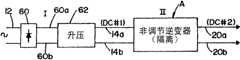
本发明是林肯电子公司(Lincoln Electric Company)开发的电弧焊接中使用的新型三级电源的改进,其中,该电源对于本发明来说不是现有技术。新型三级电源具有用于将AC信号转变成第一DC输出总线信号的输入级。该输出总线信号具有固定电压电平并且导入到图16所显示的第二级的输入端。该三级电源的新型第二级为非调节逆变器,该非调节逆变器具有隔离特性并且具有与该DC输入总线信号成比例的第二DC输出信号或第二DC总线信号。电平关系由非调节逆变器的结构所确定。非调节第二级逆变器具有开关网络,其中的开关以大于18kHz、优选为100kHz的高开关频率工作。构成电源第二级的非调节逆变器中开关网络的开关频率允许使用小磁性元件。非调节逆变器的隔离DC输出导入到电源第三级。第三级可以是斩波器或者是由例如焊接操作中的电流、电压或功率等焊接参数调节的逆变器。在本改进中,该第三级优选为斩波器。三级电源的拓扑结构具有产生第一DC信号的输入级、提供由电源第三级在调节焊接操作中所使用电流的隔离固定DC电压或DC总线信号的第二非调节DC/DC级。图1-3示出了本发明所针对的三级电源的三个例子。图1中的电源PS1包括第一级I,第二级II,和第三级III。该实施例中I级包括AC/DC变换器10,用于将AC输入信号12转变成第一DC总线信号14。输入信号12为具有可以在200-700伏特范围内变化的电压的单相或三相AC线电源信号。变换器10显示为可以是以整流器和滤波器网络形式存在的非调节器件,用于产生定义为DC#1的DC总线信号14。由于AC输入信号为线电压信号,DC总线信号14在电平上通常是均匀的。非调节逆变器A为具有隔离变压器的DC/DC变换器,将DC总线信号14(DC#1)转变成第二DC总线信号或第二DC输出信号(DC#2)。输出端20构成到III级(变换器30)的电源输入端。线20上的DC电压在线B上转变为适合焊接的电流。反馈控制或调节回路C感应焊接操作的一个参数并通过对变换器30的调节来调节线B上的电流、电压或功率。尽管可以选择使用逆变器,而实际中,变换器30为斩波器。通过具有图1所示的三级电源PS1,第二级开关网络具有通常超过变换器30的开关频率的频率。进一步的,线20的DC电压(DC#2)大致小于来自级I的线14上的DC电压(DC#1)。实际中,逆变器A中具有隔离变压器。变压器的输入或初级部分或侧的线圈匝数大致多于用来产生线20上电压的次级部分或侧。该匝数比例在实际中为4∶1,从而线20上的电压为线14上电压的1/4。对于DC#1,电压在实际中在400伏特左右。The present invention is an improvement on a new three-stage power supply used in arc welding developed by the Lincoln Electric Company which is not prior art to the present invention. The new three stage power supply has an input stage for converting an AC signal into a first DC output bus signal. The output bus signal has a fixed voltage level and is directed to the input of the second stage shown in FIG. 16 . The novel second stage of the three-level power supply is an unregulated inverter with isolation characteristics and a second DC output signal or second DC bus signal proportional to the DC input bus signal. The level relationship is determined by the structure of the unregulated inverter. The unregulated second-stage inverter has a switching network in which the switches operate at a high switching frequency of greater than 18 kHz, preferably 100 kHz. The switching frequency of the switching network in the unregulated inverter that forms the second stage of the power supply allows the use of small magnetic components. The isolated DC output of the unregulated inverter is introduced into the third stage of the power supply. The third stage may be a chopper or an inverter regulated by welding parameters such as current, voltage or power during the welding operation. In this improvement, the third stage is preferably a chopper. The topology of a three stage power supply has an input stage producing a first DC signal, a second unregulated DC/DC stage providing an isolated fixed DC voltage or DC bus signal for current used by the third stage of the power supply in regulating the welding operation. Figures 1-3 show three examples of three-level power supplies to which the present invention is directed. The power supply PS1 in FIG. 1 includes a first stage I, a second stage II, and a third stage III. Stage I in this embodiment includes an AC/
本发明所针对的三级电源的通常拓扑结构如图1所示;然而,图2示出了优选的应用,其中电源PS2具有与电源PS1大致相同的级II和级III;然而,输入级I的AC/DC变换器40包括由非调节DC/DC变换器紧接着的整流器。经变换后的信号为线14中的DC信号,作为第一DC总线信号(DC#1)。线14上的电压根据标准技术,如同所示由反馈线42调节。这样,在电源PS2中,输出焊接变换器30由反馈回路C调节。由于变换器40为功率因子校正变换器,它感应由线44代表的电压波形。通过使用电源PS2,第一DC总线信号14为在输入端12的、具有不同单相或者三相电压的固定DC电压。因此,输出20仅仅是线14上的DC电压的变换。固定电压DC#2的电平由隔离变压器和非调节逆变器A中的固定占空比确定。这是采用三个分开的且独特的级的新型电源的优选应用,其中级II为用于将固定第一DC输出或DC总线信号转化成用于驱动调节焊接变换器(例如斩波器或逆变器)的第二固定DC输出或DC总线信号的非调节逆变器。作为另一个选择,级I可以由来自线20中DC#2总线的反馈来调节。这在图2中由虚线46代表。The general topology of a three-stage power supply for which the present invention is directed is shown in Figure 1; however, Figure 2 shows a preferred application in which the power supply PS2 has approximately the same stages II and III as the power supply PS1; however, the input stage I The AC/
图3的电源PS3为三级电源的另一个应用。这不是优选的应用;然而,本发明的三级电源可以具有由来自焊接电流输出B的反馈回路52调节的输入变换器50。通过三级电源的这种使用,变换器50由焊接输出而不是电源PS2中线14上的电压来调节。通过来自焊接输出B的调节,变换器50同时是功率因子校正级和焊接调节器。然而,三级电源的应用揭示为完整的技术揭示。The power supply PS3 in FIG. 3 is another application of the three-level power supply. This is not a preferred application; however, the three stage power supply of the present invention may have the
如前所述,输入级I将单相或者三相的AC信号12转变为固定DC总线信号14(DC#1),供构成第二级II的非调节逆变器A使用。新型三级电源通常在级I采用DC/DC变换器来产生图1-3中线14所示的DC电压。可以选择级I的DC/DC变换器来在线12上产生想要的电压。图4-6显示了这些变换器中的三个,其中输入整流器60在线60a,60b提供DC电压到DC/DC变换器,该变换器可以是分别由图4,图5和图6所示的升压变换器62,降压变换器64或升降压变换器66。通过使用这些变换器,级I的DC/DC变换器引入了功率因子校正芯片,该芯片允许对功率因子进行校正从而减少电源输入端的谐波失真。功率因子校正输入DC/DC变换器的使用在焊接技术领域是公知的,并在很多现有两级拓扑结构中使用。变换器62,64,和66优选包括功率因子校正芯片;然而,这不是必须的。级I的主要目的是在线12上提供DC总线信号(DC#1)(该总线在图4-6中显示为线14a,14b)来在线12上产生固定DC总线信号(DC#2)(在相同图中显示为线20a,20b)。功率因子校正不需要利用新型三级拓扑结构。图7显示了非功率因子校正输入级,其中整流器60的输出线60a,60b由大存储电容68来耦合,从而在线14a,14b产生通常固定的电压。图7的级I没有引入功率因子校正电路或芯片。然而,电源仍然包括三级,其中第二级为非调节隔离变换器A来在线20a,20b产生通常固定的电压。输入级的另一个改进如图8所示,其中无源功率因子校正电路70连接到三相AC输入L1,L2和L3来在线14a,14b(这些线在变换器A的输入处构成DC总线14(DC#1))之间产生通常固定的DC电压。图4-8中对改进的级I的揭示在本质上仅是代表性的,可以以或者单相或者三相输入信号来使用其他输入级,可以使用功率因子校正或者不用。As mentioned above, the input stage I converts the single-phase or three-
通过在显示为线20a,20b的输出总线20提供低的固定电压,用于焊接的新型三级电源的第三级可以是斩波器或者其它以超过18kHz频率工作的变换器。非调节逆变器和调节输出变换器的开关频率可以不同。实际上,通常斩波器的开关频率大致小于非调节逆变器A的频率。图9所示电源PS4说明了本发明的使用,其中级III为用于电弧焊接类型的标准调节变换器100。该变换器由固定输入DC总线信号20驱动并由来自焊接操作120的反馈调节来提供通过输出引线102,104的适合焊接的电流。引线102为正极性引线而引线104为负极性引线。根据基于两级逆变器的电源的标准输出技术,引线102,104导入到标准极性开关110。该开关具有第一位置,其中引线102,104导入到焊接操作120的电极,从而极性开关110的输出在输出线110a具有正极性而在输出线110b具有负极性。这在焊接操作120中产生了电极正性DC焊接处理。开关网络110的极性反转可以在焊接操作中产生电极负性DC焊接处理。这样,根据标准极性开关110的设置可以进行DC负性或者DC正性的DC焊接处理。以相似的方式,极性开关110可以在电极正性或者电极负性之间进行选择,来在焊接操作120中产生AC焊接处理。这是标准技术,其中极性开关110从调节变换器100驱动DC输出端来产生AC焊接处理或者DC焊接处理。该处理由显示为导入到控制器130的线或回路122的反馈系统调节和控制,该控制器用于调节变换器100和设置开关110的极性(如线132,134分别所示)。通过在级III调节焊接操作,级II处的非调节逆变器可以具有相对较高的开关频率来减小电源第二级内的元件尺寸,并且可以具有接近100%的占空比开关来提高效率。三级电源优选实施例采用美国俄亥俄州林肯电子公司(Lincoln Electric Company of Cleveland,Ohio.)创造的“波形控制技术”。这种类型的控制系统是公知的,并且如图9A所示例性的显示,其中,当波形生成器152输出线152a上的电压时,控制电路150处理波形形状。该波形形状由反馈回路12(如具有输出端156的误差放大器154所示)控制。这样,来自波形生成器152的波形形状由反馈回路122控制并且在输出线156中产生信号。该线导入到适当的、以由振荡器162的输出端确定的高频率工作的脉冲宽度调制器。该频率高于18kHz并且通常高于40kHz。调节变换器100优选工作在低于40kHz。通常为控制器130中数字电路的脉冲宽度调制器,其输出端显示为用于通过调节变换器100控制波形的线132。根据标准操作规程,逆变器100的波形可以具有任何形状,AC或者DC。这一特征在图9A的右边部分作为波形152b,152c和152d来示例显示。波形152b为AC MIG焊接中使用类型的AC波形,该AC MIG焊接中提供了较高的负性电极安培数。较高的正性电极安培数也是常见的。在波形152c中,用于电极正性和电极负性的安培数都基本相同,而负性电极部分的长度较大。当然,可以调节AC焊接处理来提供平衡或者非平衡的AC波形(利于负性电极或者正性电极)。当极性开关110设定为DC负性或者DC正性焊接操作的时候,由波形生成器152控制显示为波形152d的脉冲焊接波形。可以由控制器130控制各种其他波形,包括AC和DC,从而焊接操作120可以调节为AC或者DC。进一步的,焊接操作可以为TIG,MIG,淹没电弧(SubmergedArc)或其他。可以由电源PS4、或其他使用本发明的电源进行任何处理。电极可以是不可消耗的或可消耗的,例如金属芯、焊剂芯或实心焊丝。根据所采用的电极可以使用保护气体或不使用。只进行DC焊接的电源PS4的改进在图10中显示为电源PS5。在该电源中,焊接操作120只进行DC焊接操作,从而反馈回路122导入到具有输出172的控制器170。调节变换器100a优选为斩波器,来产生线102a,104a之间的DC电压。如图9A所示,控制器170由波形生成器152控制。根据焊接操作120中执行的DC焊接处理的需求,线102a,104a的极性可以是电极负性或者是电极正性。调节变换器100a比图9所示电源PS4的焊接输出端简化很多。图9和图10,以及图9A所示的控制网络或电路150,说明了新型三级电源的多功能性。The third stage of the new three stage power supply for welding may be a chopper or other inverter operating at frequencies in excess of 18kHz by providing a low fixed voltage on the
对于在这两种类型的电源中使用的调节和非调节开关网络,都必需为操作控制器提供电压。图11说明了这样结构和方案,用来得到控制电压来操作三级电源(例如电源PS6)的各种控制器。使用前置调节器的输出来提供用于前置调节器开关控制器和两级电源第二级开关控制器的控制电压是公知的,并且由在这里作为参考引用的Moriguchi的专利5,926,381所揭示。用于进行焊接操作的输出斩波器按常规从到斩波器的输入DC电压获得控制器控制电压。这两个公知的技术在电源PS6中采用。三级电源可以由具有从电源中不同位置得到的电源供应的控制器进行操作。具体的说,电源PS6具有电源供应180,其具有输出182以及来自引线14a,14b上的第一DC总线(DC#1)信号的输入184,186。电源供应180包括降压变换器或反激变换器(未显示)来将图2前置调节器40输出端的高电压减少为线182上的低电压。该控制电压可以在5和20伏特之间。线182上的电压导入到具有输出引线192的控制器190来根据标准技术进行前置调节器40的操作。前置调节器具有图2和3所示的反馈线42,44,但是未在图11中显示。非调节逆变器A不需要控制器来调制占空比,或者输入电压与输出电压之间的固定关系。然而,它确实需要从来自电源供应180的线196中接收控制器操作电压的控制器194。除了第二级控制器194不是与现有技术两级电源中使用相同的调节控制器之外,这一配置与Moriguchi的专利5,926,381所揭示的概念相似。作为选择,电源供应PS#3由输入12的一个相来驱动以给出如虚线176所示的可选择电源供应电压。级III的调节输出变换器30具有标注为PS#2的电源供应200,其具有由显示为包括引线20a,20b的DC总线20(DC#2)所确定的线202上的控制器电压。再次的,电源供应200包括降压变换器或反激变换器来将非调节变换器A输出端的DC总线信号转变为供具有输出212的控制器210使用的较低电压。如同分别根据图1和图2中的PS1和PS2所讨论的,线212上的信号根据线C上的反馈信号调节焊接变换器30的输出。DC总线信号14(DC#1)和DC总线信号20(DC#2)提供到电源供应180,200的输入端,所述电源供应是用来产生用于控制器190,194和210的低电平DC控制电压的DC/DC变换器。作为虚线220所显示的可选择的方案,标注为PS#2的电源供应180可以提供用于控制器210的控制电压。图11已经被揭示来说明使用具有控制器的三级电源的多功能性,该控制器可以接收来自显示为PS#1和PS#2的各种固定DC电压的减小的供应电压。可以采用其他配置来提供控制器电压,例如,以显示为PS#3的方式,通过一个变压器连接到AC输入电压12的一个相的整流连接。For both regulated and non-regulated switching networks used in both types of power supplies, it is necessary to provide voltage to operate the controller. Figure 11 illustrates such structures and schemes for various controllers for obtaining control voltages to operate a tertiary power supply (such as power supply PS6). Using the output of a pre-regulator to provide control voltages for a pre-regulator switching controller and a two-stage power supply second-stage switching controller is known and disclosed by Moriguchi patent 5,926,381 incorporated herein by reference. The output chopper used to perform the welding operation conventionally derives the controller control voltage from the input DC voltage to the chopper. These two known technologies are employed in the power supply PS6. A tertiary power supply can be operated by a controller with power supplies drawn from different locations in the power supply. In particular, power supply PS6 has a
图12的电源PS7与具有相同标注号码元件的电源PS6相似。输出级III为用于将电极E和工件W之间的DC电流导入的斩波器230。电流分流器S提供到控制器210的反馈电压C。级II的高开关速度变压器240具有目前为止所描述的特征,其具有由具有初级线圈252和次级线圈254的变压器250所提供的隔离。DC/DC变换器240的初级侧为导入一个可选择电流到初级线圈252的开关网络。来自次级线圈254的整流输出为变换器240的次级部分或侧。变换器240采用具有由控制器194设定占空比或者相位偏移的高开关速度逆变器。在该电源的实际版本中,开关频率大约为100kHz。在斩波器230的焊接操作中,占空比保持不变;然而,如具有用于调节控制器194的输出262的“ADJ”电路260所示,可以调节逆变器的占空比或者相位偏移。占空比通常接近100%,从而在变换器240初级侧的开关对以它们的最大时间导通在一起。然而,为了改变第一DC总线14和第二DC总线20之间的固定关系,电路260可以用于调节占空比或者相位偏移。这样,非调节隔离逆变器240变为具有不同但是固定的占空比。然而,占空比通常非常接近100%,从而开关大致同时被操作。在三级电源的通常应用中占空比可能在80-100%之间变化。在新型电源的优选应用中,图4所示的升压变换器62用作功率因子校正输入级I。该升压变换器根据具有前述控制电压182的控制器190而工作。根据该微小的修改,电源供应270具有由通过单相或三相AC输入12的一个相的线274连接的变压器。电源供应270中的整流器和滤波器产生最优虚线276中的低控制电压,用于按照需要代替线182中的控制电压使用。这两个选择不影响电源PS7的操作特性。用于电弧焊接的三级电源的其他修改可以从前面的描述和焊接领域的公知技术获得。The power supply PS7 of Figure 12 is similar to the power supply PS6 having like numbered elements. The output stage III is a
输入级I通常包括图4-8所示的整流器或者功率因子校正DC/DC变换器。这些输入级可以用于表示为输入12的各种电平的单相和三相AC信号。参考图13-16中的电路,揭示了三相AC输入电源的输入级的某种形式。这些电路中的每个具有三相输入和以输入级的低谐波失真因子和高功率因子获得的DC总线输出(DC#1)。图1-12的揭示通常适用于新型三级电源;然而,使用的特定级I与现有技术两级电源或者新型三级电源都相关。图13中,级I的输入电路300包括具有输出引线302a,302b的三相整流器302。升压开关310与电感312,二极管314和并联电容316串联。适当电路320(作为标准功率因子校正芯片)具有用于确定输入电压的输入322,调节反馈线322a和用于操作升压开关来使输入12中的电流与输入电压具有大致相同的相位的输出324。该芯片为可以用于本发明的标准三相功率因子校正升压变换器芯片,也用于常规两级电源。以相似的方式,图14所示输入电路330具有如前所述具有输出引线302a,302b的三相整流器302。保括电感350,二极管352和电容356,358的升压电路用于与开关340,342连接,来提供电路330输出端的电流和输入电压12之间的协调。为了实现这一目的,控制芯片360根据输入366中的感应电压和线367,368中的反馈调节信号提供线367,368中的选通脉冲。这是提供形成两级电源或新型三级电源输入的类型的三相功率因子校正的标准技术。已经发现有源三级电路300,330在三相输入上操作时提供大约为0.95的输入功率因子。在具有单相AC输入时,级I的功率因子可以向上校正到大约0.99。由于三相电源通常只能校正到较低程度,已经发现用于两级电源或新型三级电源输入级I的无源电路在某种程度上与有源功率因子校正电路的能力相当。图15显示了标准无源电路400,其中三相中的每一相由三相整流器302整流,该整流器302通过输出引线302a,302b将DC电流导入到包括电感412和电容414的滤波器电路。已经发现例如图15所示的无源电路可以将三相输入的功率因子校正到通常大约为0.95范围内的程度。这在某种程度上与三相输入电路有源功率因子校正电路的能力相当。图16显示了降压升压输入电路420。线302a,302b上的整流电流首先由开关422使用具有来自输入12的电压波形信号的线#32的标准功率因子校正芯片430进行降压,也驱动芯片434操作升压开关440。开关422,440一致的工作,使用包含电感器450,二极管452和电容454的电路来控制输入功率因子。电路300,330,400和420为使用标准技术的标准三相无源功率因子校正电路以及由输入电压波形和DC#1电流控制的可用开关。图13-16为可以对三级电源第一级进行的某种修改的说明。当然,存在其他技术来提高功率因子并且同时减小用于驱动电弧焊接电源的类型的DC和AC信号的谐波失真。The input stage I usually includes a rectifier or a power factor corrected DC/DC converter as shown in Figs. 4-8. These input stages can be used for single-phase and three-phase AC signals of various levels indicated as
级II的非调节逆变器A可以使用各种逆变器电路。优选电路如图17所示,其中逆变器在到隔离变压器250初级线圈252的输入定义的初级部分或侧和由次级线圈254输出所定义的次级部分或侧之间被分开。首先说明变换器A的初级部分或侧,采用了全桥电路500,其中跨接在电容548上的成对开关SW1-SW3和SW2-SW4由引线502,504连接。开关分别由线510,512,514和516的选通脉冲以可变顺序加电。控制器194输出线510-516中的选通脉冲以及如前所述由来自电路260的线262上的逻辑所确定的调节占空比。通过改变线510和512以及线514和516的相位偏移控制占空比。电路260调节成对开关的占空比或相位偏移。该调节在逆变器A的操作中是固定的。实际中,电路500具有大约100%的占空比或相位偏移,其中每对开关具有最大的重叠导通周期。如前所述的,控制器194也具有来自由线196所示的适当电源供应的控制电压。在电路500的操作中,通过初级线圈252导入可变电流。该电流具有通常至少大约100kHz的超高频率,从而可以减小元件的尺寸,重量和成本。高开关频率不是焊接操作所规定的,而是为三级电源的非调节级A的效率而选择的。块电容与初级线圈串联来防止非调节选通驱动信号带来的饱和。逆变器A的次级部分或侧为具有同步整流器件522,524的整流器520。同步整流器件在通常电机工程技术领域是公知的,并且由在这里参考引用的Boylan的专利6,618,274所讨论。这些器件由线526,528上的,在次级线圈254相反端根据标准技术产生的信号选通。引线530,532和534形成整流器520输出引线来产生通过引线20a,20b的DC电压(DC#2)。根据标准焊接技术,电流通过扼流器544进行平滑并且跨过电容546。逆变器A为非调节的,这意味着它不是由来自焊接操作的实时反馈信号进行调节的。它仅将DC总线信号12(DC#1)转变为DC总线信号20(DC#2)。这一转变允许导入到使用逆变器A的电源的调节第三级的电压充分的减小。电压减小主要由变压器250线圈匝数比决定,在优选实施例中该比例大约为4∶1。对于DC#1,电压大约为400伏特。这样,输出总线20的固定电压大约是第一级输出总线12固定电压的1/4。在这里作为背景信息参考引用的Dr.Ray Ridley的标题为“The incredible Shrinking(Unregulated)Power Supply”文章中包含了非调节级的几个优点。一个基本的优点是将频率增加到超过100kHz来减小逆变器级的尺寸和成本。The unregulated inverter A of level II can use various inverter circuits. A preferred circuit is shown in FIG. 17 where the inverter is split between a primary part or side defined by the input to the
不同的电路可以用作构成本发明新型级II的非调节变换器A。逆变器的特定类型不是控制。已经使用了几种逆变器。在图18-21中说明了一些逆变器。在图18中,逆变器A显示为在变压器250的初级侧使用全桥电路600。如同参考图17所示逆变器A版本所解释的,开关和二极管并联电路602,604,606和608根据标准相位偏移全桥技术而工作。逆变器A内部工作的修改如图19所示,使用了具有串联的开关电路610,612和614,616的级联桥。这些开关电路与半桥相似的工作,包括为与电容620并联且与二极管622、624串联的开关电路提供能量的输入电容548a,548b。这两个开关电路串联,从而当使用与用于图17的全桥变换器的技术相似的相位偏移控制技术的时候,单个开关上具有降低的电压。在这里参考引用的Canales-Abarca的专利6,349,044中揭示了这种类型的逆变器开关网络,其中说明了使用级联桥的逆变器,有时也称为三电平逆变器(Three Level Inverter)。图20说明了双前向逆变器(Double Forward Inverter),其中开关630,632在变压器250a初级线圈的部分252a中提供脉冲。以相似的方式,开关634,636一致地工作以在初级部分252b提供相反极性的脉冲。该交互脉冲在变压器250a初级线圈产生AC,从而在次级线圈254中产生隔离的DC输出。图21中以逆变器A的结构显示了标准半桥电路。该半桥电路包括交替开关的开关640,642以在变压器250初级线圈252产生AC。可以使用这些或者其他开关电路以在变压器250初级线圈产生AC信号,从而对次级隔离的AC信号进行了整流并作为DC#2从引线20a,20b输出。特定代表性标准开关电路的描述仅是说明性的,而不能认为是穷举的。在第二级中不进行焊接电流的控制。在该级中,为了驱动第三级的目的,具有高电压的DC总线信号被转换成具有低电压的固定DC总线信号(DC#2),该第三级是为电弧焊接提供适合电流的调节级。电弧焊接引入并且试图包括其他焊接相关应用,例如等离子体焊接的概念。在三级中使用的各种电路可以组合来构成用于三级电源基本拓扑结构的各种结构。Different circuits can be used as unregulated converter A constituting the novel stage II of the invention. The specific type of inverter is not the control. Several inverters have been used. Some inverters are illustrated in Figures 18-21. In FIG. 18 , inverter A is shown using a
较佳实施例(图22-24)Preferred Embodiment (Figure 22-24)
在图22中,改进的三级电源的前两级包括图17所最优显示的非调节变换器A,其中线14a,14b之间的输入DC信号由显示为具有由线604中的选通信号开关的电源开关602的升压变换器600的新型第一输入级提供。开关602在附属开关628接通之后接通。线192和192a中选通信号时间设定由功率因子校正控制器194进行。根据标准升压技术,线192中的高频信号引起具有反并联二极管602a的主电源开关602栅604中的高频开关信号。按照以前的讨论控制栅604上信号的时间设定,来获取在输入引线12a,12b上产生整流信号的电源的功率因子校正。由开关602和整流器二极管将引线12a,12b上的DC信号转换成引线14a,14b上的DC总线信号。本发明涉及具有包括具有电感622的第一支路和具有寄生电容624的第二支路的网络的有源软开关电路620的使用。网络由串接的附属开关628操控。一些讨论以储能电路和谐振电路区分这两个支路。这在技术上是合理的,但是对于软开关功能是不必需的。电容624和电感622形成用于软开关601的滤波器电路,其中电容640通过二极管D2引起升压二极管软电压接通。该升压二极管有时以输出或者整流二极管来提及。电路620为有源软电路,其在开关事件时控制跨过电源开关602以及输出二极管610的电压和电流。这样,升压变换器600中的电源开关606以及升压或输出二极管610通过软开关进行了变换。这一特征使得该开关技术对于升压二极管受到严重反向恢复问题的高压变换应用特别有吸引力。例如,在功率校正升压电路中,电源开关和整流器二极管都经受高电压。通过采用的传统脉冲宽度调制技术,由于少数整流器二极管610的反向恢复,高开关损耗、高EMI噪声以及器件失效问题变得更加显著。因此为功率开关602以及二极管610都使用软开关是有好处的。逆变器中开关的电压和电流的波形除了在接通和关断开关间隙发生零电压开关转换的时候,基本是方波。电源开关和升压二极管都经受了最小电压和电流应力。由于其只处理少量的谐振转换能量,附属开关628与主开关相比可以非常小。由于在没有增加开关电压和开关电流下实现了软开关,当使用有源电路620的时候传导损耗没有实质增加。基本上,选择电路620以在电源开关602的转换中(可选择地,在输出二极管610的转换中)提供电流和电压两者中的软开关。这样,使用两级变换器来将线12a,12b上的DC信号转换成线20a,20b中的DC信号。通过在升压变换器600具有软开关电路并使用非调节逆变器A的固有软开关,彻底地增进了两级器件的效率。因此,图22所示两级DC/DC变换器对于三级焊接电源输入侧是实质性的进步。在工作中,线192中超过18kHz的高频开关信号首先通过192a中的选通信号给附属开关628加电压,从而激活由电感622和电容624形成的谐振储能电路。开关628接通以后,主开关602接通。这引起在电流和电压两者中的软开关。同时,电路620的无源部分控制通过输出整流器二极管610的电压和电流。附属开关628的正极性侧由二极管D1箝位到电容640。这将软开关电路箝位到正性输出,具有电感和电容支路的该软开关电路在工作中不浮空。标题为“HighEfficiency Telecom Rectifier Using a Novel Soft-Switching Boost-Based InputCurrent Shaper”的1991年IEEE文章中讨论了图22所示电路。该文章在这里作为参考引用。在标题为“A New ZVT-ZCT-PWM DC-DC Converter”的2004年IEEE文章中描述了用于电源开关602的相似的软开关电路。用于电源开关602的这一相似类型的有源软开关电路如图23所示,其中对于图22所示相同元件使用相同数字。有源软开关电路700具有谐振电感704,706,该谐振电感划分为段并且通过公共核心705耦合。电流分别控制二极管704a,706b。这些二极管与多个电感串联,该多个电感依次与寄生电容708并联。附属开关710具有反并联二极管712,使得开关710根据前面讨论的图22中附属开关628而工作。软开关电路700包括用于控制通过输出整流器610的电压的电压控制电容720。为了将附属开关710的正性侧箝位到输出引线14a,提供了单个二极管730。该二极管作为图22所示二极管D1,D2来工作。软开关电路700提供为跨过开关602的电压和电流提供软开关并在整流器二极管610的开关中控制电压和电流。这样,电路700基本上以与前面讨论的软开关电路600相似的方式工作。本发明涉及用于电源开关602(可选择地用于整流器二极管610)的有源软开关电路。软开关电路的拓扑结构可以分别以由图22,23所示的优选软开关电路600,700而变化。开关SW1,SW2,SW3和SW4为具有反并联二极管的固体开关(例如二极管602a)。进一步的,电容506a防止变压器核心250a的饱和。In FIG. 22, the first two stages of the modified three-stage power supply include the unregulated converter A best shown in FIG. The novel first input stage of the
通过为三级电源升压输入级提供有源软开关电路,输入级的工作结合了第二非调节变换器级的固有软开关特性来提供提高新型三级电源(图1-21所示)效率的两级输入。已经发现电路700在开关602的高速开关中推动该电压下降到接近零。电路600降低该电压,但是使用电路600的开关中,该电压不是严格为零。实际上,其可以为50伏特。因此,软开关电路600由于较低成本而被优选,软开关电路700由于具有在开关602的开关中推动实际电压下降到接近零的能力而供选择。这些区别是说明两种在上述新型三级电源输入级使用的分立有源软开关电路的原因。By providing an active soft-switching circuit for the boost input stage of the three-level power supply, the operation of the input stage combines the inherent soft-switching characteristics of the second unregulated converter stage to provide improved efficiency of the new three-level power supply (shown in Figure 1-21) two-stage input.
图24再次显示了图12所示的三相电源,其中斩波器230显示为具有由来自控制器210的线212上的高频选通信号控制的电源开关750。通过读取分流器S产生来自电流感应器件760的线762上的反馈信号。以相似的方式,从电压感应器件770通过线772导入电压反馈信号到控制器210。这两个控制信号控制在用于操作斩波器230的电源开关750的控制器210中的脉冲宽度调制器的工作。输入电容780根据标准应用控制通过输入引线20a,20b的电压。本发明可选择的形式是为斩波器230提供无源软开关电路800,斩波器的无源软开关与输入级的有源软开关以及第二级的固有软开关结合,来增加图12所示并由图1-21所描述的三级电源的效率。软开关电路800为通用的软开关电路。该电路包括用于控制通过电源开关和二极管D4的电流的电感802。电容806在开关操作中控制通过电源开关的电压。电容804和806由二极管D1,D2,D3和D4连接。这两个电容控制通过二极管D4的电压。这样,电源开关750和二极管D4在开关操作中,在电流和电压中都被软开关。加州大学标题为“Properties and Synthesis of Passiv,Lossless Soft SwitchingPWM Converters.”的文章中说明了这种电路。这一1997年五月的文章在这里作为参考引用,来说明通常使用的软开关电路800的工作。本质上,斩波器230包括具有软开关电路的电源开关,以在接通和断开过程中控制电流和电压两者。换言之,输出斩波器230提供有软开关电路,该软开关电路在开关操作中的适当时间控制电压和电流两者。FIG. 24 shows again the three phase power supply shown in FIG. 12 with
图1-21所描述的三级电源提供了具有有源软开关电路的输入级,该输入级与非调节逆变器A的固有软开关结合,从而通过减少电源输入端的开关损耗和传导损耗来提高整体效率。作为选择,斩波器输出级具有无源软开关电路来提供廉价的最后级。斩波器可以是分立的可替换模块,不需要电路修改来象有源软开关电路所需要的那样控制附属开关。三级电源输入部分包括与非调节相位偏移脉冲宽度调制级结合的有源功率因子校正级。前两级的这一新型结合对于电弧焊接非常有效并且作为电弧焊来说是廉价的拓扑结构。The three-stage power supply described in Figure 1-21 provides an input stage with active soft-switching circuitry that, combined with the inherent soft switching of the unregulated inverter A, reduces switching and conduction losses at the input of the power supply to Improve overall efficiency. As an option, the chopper output stage has passive soft switching circuitry to provide an inexpensive final stage. The chopper can be a discrete, replaceable module that requires no circuit modification to control the accessory switch as is required for an active soft-switching circuit. The three-stage power input section includes an active power factor correction stage combined with an unregulated phase-offset pulse-width modulation stage. This novel combination of the first two stages is very efficient for arc welding and is an inexpensive topology for arc welding.
如图22,25和26所示,第一级600为升压类型的DC/DC变换器,其包括:耦合在输入引线12a和主内部节点603之间的电感644,耦合在内部节点603和较低变换器输入引线12b之间的、具有二极管602a的主开关器件602。主整流器610,在节点603耦合其正极,并且在输出引线14a耦合其负极。可选择的输出滤波器548通过输出引线14a,14b连接。如同在常规升压变换器的操作中那样,主开关由位于其控制栅极的脉冲宽度调制(PWM)控制信号激活,从而在导通(ON)状态和非导通(OFF)状态(放电阶段)之间切换,在导通状态中内部节点603被驱动到大致为较低引线12b的电压(充电阶段)。在每个充电阶段之前,假设主开关器件602已经处于非导通状态(OFF)相对较长的时间,通过输出电容548的电压等于输入电压加上电感644的电压。主开关602的关闭将节点603的电压大致带到较低引线12b的电压,因而输入电压加到电感644两端(端12a相对节点603为正性)并且主二极管610防止滤波器电容548通过主开关602放电。通过电感644的电压引起流过其中的电流随时间增加,从而在电感644中存储了相应的能量。此后,主开关602被关闭(OFF)来开始放电阶段。将开关602置于非导通状态引起主电感电压变化,使得节点603的电压升高来将流过电感644的电流保持在常数,其中为了电感电流的持续流动,节点603的电压必需升到足够高来前向偏置二极管610(例如接近跨过电容548的输出电压加上二极管降落),其中在放电阶段中电感电压改变极性。对于大输出电容548,引线14a和14b之间的输出电压在放电阶段中保持常数,其中充电和放电(主开关602接通和断开的切换)以适当的反馈而重复进行,从而调节开关控制信号的脉冲宽度调制,使得通过电容548的输出电压可以保持在需要的DC数值。As shown in Figures 22, 25 and 26, the
通常,需要将电源中每一级的效率最大化,其中将主开关602的接通状态电阻,二极管正向电压降落,以及主二极管610的反向恢复时间等级被理想化地最小化来抗击传导损耗。另一个考虑是将在变换器级600中的开关损耗和噪声产生最小化,其中需要控制开关602和二极管610的转换发生的条件。具体而言,在升压变换器600中可以优先采用软开关电路来提供零电压开关接通或断开,以及二极管610的零电压或零电流断开。缺少反测量,主开关602的开关引起对开关602和/或对主二极管不期望的功率损耗和应力。因此,在升压变换器级600中采用软开关或缓冲器电路来提供这些元件的低电流或低电压开关。在这一点上,可以使用软开关电路以在开关602断开的时候将通过开关602的电压升高率最小化(例如节点603处的dv/dt),并在开关602接通的时候将通过开关602的电压最小化,同时在二极管610的反转中将其电压或电流中的一个或者两者都最小化,以减少开关损耗和噪声发射。In general, it is desirable to maximize the efficiency of each stage in the power supply, where the on-state resistance of the
可以在图24所示三级电源升压级600中使用Hua的专利5,418,704所说明的软开始开关电路。该专利由参考引用,并且与图25所示第一实施例电路以及图26所示优选实施例电路不同。Hua的专利5,418,704所说明的软开关电路采用具有谐振电感和电容的附属开关,来提供升压变换器主开关和输出二极管零电压切换。该公开中以谐振电路提及本发明的两支路网络。在Hua的专利中,附属开关和谐振电感跨过主变换器开关而串行连接。附属开关在接通主开关稍前进行开关,从而谐振电感为耦合到正性变换器输出引线的二极管,来限制主二极管电流的变化率。Hua的附属开关网络的激活也将内部节点放电到零伏特,从而保证了主开关大致在零伏特接通。然而,Hua在主晶体管断开时受到硬开关条件的影响。具体而言,Hua的上部主开关端电压在谐振电感可以将任何电流传导到输出端之前必须高于变换器输出电压,因而Hua的谐振电感在晶体管断开过程中引起非常快速的晶体管电压升高(高dv/dt),导致不可接受的开关损耗。The soft-start switching circuit described in Hua's 5,418,704 patent can be used in the three-stage
如图25和26所示,典型升压变换器600包括有源软开关电路601或601a,分别用于提供主开关602和主二极管610的软开关。图25的典型软开关电路606(本发明的原始版本)为三端网络,其具有跨过主开关602耦合的第一和第二端,以及耦合到主二极管610负端的第三端。软开关电路或网络包括电感622、具有二极管630的附属开关器件628。第一和第二二极管D1和D2,与电容624和640一起构成三端缓冲器电路606。主和附属开关器件602和628可以是根据位于其控制端的控制信号,在其第一和第二电源端之间选择性的提供通常传导和通常非传导状态的任何适当电路,包括但不局限于三极管晶体管、金属-氧化层-半导体(MOS)器件、隔离栅三极管晶体管(IGBTs)等。电感622位于与开关602并联的第一支路中。电感622具有耦合到主电感644的第一端和连接到第一中间电路节点607的第二端。附属开关器件628耦合在节点607和变换器引线12b,14b之间。二极管630可以是附属开关器件628的体二极管或者可以是分立的元件。二极管630的正极耦合到下部变换器引线12b,14b,并且其负极耦合到位于附属开关628和谐振电路622连接处的节点607。与Hua的电路相似,电容624跨过主开关602耦合在电路606中。然而,不象Hua,图25中软开关电路606具有第二中间节点609,其具有耦合在节点603和609之间的第二电容640。软开关电路或网络601的第一二极管609具有耦合到第一内部节点607的正极和耦合到第二内部节点609的负极。二极管D2具有耦合到第二内部节点609的正极和耦合到位于上部变换器输出端14a的主二极管负极的负极。As shown in Figures 25 and 26, a
作为Hua的具有附属开关硬开关的技术发展,图25的软开关电路601为主开关602和主二极管610两者以及附属开关628的接通和断开提供软开关操作。这一改进得到了更好的效率,较低的元件应力,以及较低的噪声生成。在接通主开关602之前,当节点603的电压等于输出电压的时候对附属开关628进行接通,其中附属开关628的断开引起通过谐振电感622的电流升高到主电感器电流的水平,主二极管610由此反向。随着二极管610恢复电压反向并且开始阻断来自输出端的电流,来自电感644和622的电流对电容624放电,其中跨过二极管610的电压在反向中保持很小来将二极管开关损耗和噪声生成最小化。当电容624放电以后(例如当跨过开关602的电压为零),主开关602随之接通,附属开关628断开。通过谐振电感622的电流通过二极管D1对第一谐振电容640充电,也对附属开关628的任何寄生电容充电,从而节点607和609的电压向变换器输出的电平升高,并且二极管D2开始导通。将来自电感622的任何剩余能量通过二极管D1和D2提供给输出端。当开关电压基本为零时,主开关602接着断开(在根据基于输出电平反馈的电流脉冲宽度调制的时间上)。通过主电感644的电流对电容624充电并通过二极管D2对谐振电容640放电。这一动作引起节点607的电压升高到输出值,此后主二极管610再次开始将电流传导到输出端。As a technical development of Hua's hard switching with sub-switches, the soft-switching circuit 601 of FIG. This improvement results in better efficiency, lower component stress, and lower noise generation.
在图25的电路606的工作中,当主开关602开始关断的时候,主电感器电流流过电容640和第二二极管D2,主二极管610在谐振电容640放电以后开始导通,其中跨过第一电容640的电压为其电容、主电流电平、脉冲宽度调制主开关602占空比的函数。以这种方式,可以通过保证在二极管开始导通电流到输出电容548时的零电压,将主二极管610的开关损耗减小或最小化。在主开关处于接通状态时,由于第一二极管D1防止了电容充电(除了在附属开关628首先断开并且节点607的电压高于跨过电容640的电压时),跨过第一谐振电容640的电压保持为常数。理想地,如果在主开关接通的升压阶段中谐振电容640完全放电,主开关602具有零电压断开条件。然而,如果谐振电容640没有完全放电主,开关602将受到非零断开电压。另外,电容640在附属开关628断开时可以仅为附属电感622提供电流旁路通路,没有为图25的软开关电路606中附属电路环路中的寄生电感提供有效的旁路传导通路。因此,附属开关628从接通到断开的转换可以在非零电压进行,从而可能有开关损耗和噪声产生,以及对开关628的可能应力。In the operation of the
图26说明了软开关电路606a的优选实施例和优选设计,并且根据本发明,去除了电容624。第二电容640a耦合在内部节点609和下部变换器引线12b,14b之间,从而从电容640和640a的串联组合(该串联组合作为跨过主开关602的并联支路)中得到了净电容。下部(第二)电容640a通过二极管D1跨过附属开关628并联。在一个特定的应用中,下部电容640a大体上小于上部电容640。这样,与图25的软开关电路不同,图26的电路601a在第二内部节点609和下部变换器引线12b,14b之间以两个电容640,640a提供了电容624。这种几何形状帮助为附属开关628提供软开关(例如减小跨过开关628的dv/dt)。Figure 26 illustrates a preferred embodiment and preferred design of soft switching circuit 606a, and in accordance with the present invention,
现在参考图27,曲线图800示出了升压变换器级600中分别与主和附属开关602和628相关的各种典型波形。同时显示了图26的典型有源软开关电路601a。曲线图800示出了对应附属开关控制电压信号的电压波形810(根据开关类型,例如栅极信号VGS,基极信号VBE等),代表跨过附属开关628的电压(例如内部节点607和下部变换器引线12b,14b之间的电压)的电压波形820,以及说明通过附属开关628的开关电流的电流波形830。此外,曲线图800也提供了说明主开关602控制电压信号的电压波形840,以及代表跨过主开关602的电压(例如节点603和下部变换器引线12b,14b之间的电压)的电压波形850。Referring now to FIG. 27 , a
曲线图800示出了变换器级600的典型开关周期中的各种离散时间,包括主开关602断开(例如电压波形840下降沿)的时间870,附属开关628接通(控制信号810的上升沿)的时间872,以及附属开关628断开而主开关602接通(波形810下降沿和波形840上升沿)的时间874。虽然显示为在时间874同时切换,附属开关628可以可选择地在主开关接通时间之前、同时或之后断开,其中认为所有这种各种应用落入本发明以及所附权利要求的范围之内。在图26所示电路示例说明的应用中,主开关602在时间870断开,其后如曲线图800中部分852和部分822分别所示,跨过主和附属开关602和628的电压(例如节点603和607的电压)升高。注意到,跨过主开关602的电压曲线850在主开关在时间870接通时为零,从而减轻了任何对应的开关损耗和/或噪声发射。如图27所示,开关电压曲线820和850在部分824和部分854保持基本常数直到附属开关628接通的时间872(主开关602保持断开)为止,其数值通常等于跨过输出滤波器电容548的电压的数值(VOUT),从而附属开关电压在点826降落到零。注意到,附属开关电流曲线830在时间872大致为零,从而附属开关628不会受到显著的接通开关损耗。此后,在时间874,主开关602再次接通。注意到,在时间872和874之间,主开关电压曲线850在开关602接通之前通常在部分856降落到零,因此提供了零电压接通条件来将主开关602的开关损耗和噪声产生最小化。此外,与上面图25中电路或者网络601不同,附属电流曲线830在附属开关接通时间872之后在部分832开始增加,但接着在附属开关断开时间874之前在部分834减少到接近零,从而附属开关的断开为具有最小化(例如零)开关损耗和噪声发射的软开关事件。主开关602接着在874大致零伏特接通,并且附属开关电压820在部分828增加直到通过谐振电感622的电流降落到零的时间。此后,该周期继续直到下一个时间870,在该时间上,主开关602再次断开,其中主开关602在给定周期中保持接通的时间量可以通过脉冲宽度调制或者其他适合的技术由输出调节条件确定。图26的电路601a提供了附属开关628的软开关,而电路601中的附属开关628具有硬断开。这是由图26的优选电路601a获得的明显进步。
图25和26的软开关系统或网络601,601a分别包括与主电源开关602并联的两个并联支路。第一支路包括控制到附属开关628、开关602以及二极管610的电流的电感622的电感,而第二支路具有控制跨过开关602的电压的电容。图26中,该并联支路分为两个电容,其中之一控制跨过附属开关628的电压。The soft switching systems or networks 601 , 601a of FIGS. 25 and 26 respectively comprise two parallel branches connected in parallel with the
图26的电容640,640a的电容通常等于图25电容624的电容。电容640在开关628断开时对其进行软开关。随着开关628断开,电容640a处于零电压。它缓慢的充电来提供软断开。当开关628接通,开关中的电流通过电感622缓慢的增加,并且二极管610由电感中电流缓慢的增加而断开。这样,网络601a在接通和断开周期期间软开关开关628,并且控制通过升压或输出二极管610的电流。这是对图25的网络601的改进。The capacitance of
所揭示的各种开关电路和电源拓扑结构可以以多种方式结合来完成所要求保护的发明的目标和优点。The various switching circuits and power supply topologies disclosed can be combined in various ways to accomplish the objects and advantages of the claimed invention.
Claims (23)
Applications Claiming Priority (2)
| Application Number | Priority Date | Filing Date | Title |
|---|---|---|---|
| US11/087,179 | 2005-03-24 | ||
| US11/087,179US8581147B2 (en) | 2005-03-24 | 2005-03-24 | Three stage power source for electric ARC welding |
Publications (2)
| Publication Number | Publication Date |
|---|---|
| CN1838517A CN1838517A (en) | 2006-09-27 |
| CN100547896Ctrue CN100547896C (en) | 2009-10-07 |
Family
ID=36678595
Family Applications (1)
| Application Number | Title | Priority Date | Filing Date |
|---|---|---|---|
| CNB200510115823XAActiveCN100547896C (en) | 2005-03-24 | 2005-11-09 | Improved three-stage power supply for arc welding |
Country Status (11)
| Country | Link |
|---|---|
| US (1) | US8581147B2 (en) |
| EP (2) | EP2390041A1 (en) |
| JP (1) | JP4303714B2 (en) |
| KR (1) | KR100675117B1 (en) |
| CN (1) | CN100547896C (en) |
| AU (1) | AU2005237177B2 (en) |
| BR (1) | BRPI0504581A (en) |
| CA (1) | CA2518125C (en) |
| MX (1) | MXPA05011461A (en) |
| PL (1) | PL1704954T3 (en) |
| TW (1) | TWI314490B (en) |
Cited By (2)
| Publication number | Priority date | Publication date | Assignee | Title |
|---|---|---|---|---|
| CN103872893A (en)* | 2012-12-11 | 2014-06-18 | 三星电机株式会社 | Power factor correction circuit and power supply having the same |
| CN103872894A (en)* | 2012-12-11 | 2014-06-18 | 三星电机株式会社 | Power factor correction circuit and power supply having the same |
Families Citing this family (145)
| Publication number | Priority date | Publication date | Assignee | Title |
|---|---|---|---|---|
| US8269141B2 (en) | 2004-07-13 | 2012-09-18 | Lincoln Global, Inc. | Power source for electric arc welding |
| US9956639B2 (en) | 2005-02-07 | 2018-05-01 | Lincoln Global, Inc | Modular power source for electric ARC welding and output chopper |
| US8581147B2 (en) | 2005-03-24 | 2013-11-12 | Lincoln Global, Inc. | Three stage power source for electric ARC welding |
| US8785816B2 (en)* | 2004-07-13 | 2014-07-22 | Lincoln Global, Inc. | Three stage power source for electric arc welding |
| US9855620B2 (en) | 2005-02-07 | 2018-01-02 | Lincoln Global, Inc. | Welding system and method of welding |
| US9647555B2 (en) | 2005-04-08 | 2017-05-09 | Lincoln Global, Inc. | Chopper output stage for arc welder power source |
| US8969763B2 (en)* | 2006-10-17 | 2015-03-03 | Lincoln Global, Inc. | Remote sense lead magnitude and polarity detection controller |
| DE102007002342B3 (en)* | 2007-01-16 | 2008-10-16 | Friwo Mobile Power Gmbh | Simplified primary-side drive circuit for the switch in a switching power supply |
| JP2008187821A (en)* | 2007-01-30 | 2008-08-14 | Matsushita Electric Works Ltd | Insulated ac-dc converter and dc power supply unit for led using it |
| CN101350557B (en)* | 2007-07-18 | 2011-04-27 | 华为技术有限公司 | A power adjustment device |
| DE102007042771C5 (en)* | 2007-09-07 | 2015-02-12 | Robert Bosch Gmbh | Method for operating the power supply of an resistance welding device |
| EP2051360B1 (en)* | 2007-10-17 | 2016-09-21 | Power Systems Technologies GmbH | Control circuit for a primary controlled switching power supply with increased accuracy of voltage regulation and primary controlled switched mode power supply |
| CN101197540B (en)* | 2007-12-11 | 2010-06-16 | 艾默生网络能源有限公司 | a DC converter |
| US8693213B2 (en) | 2008-05-21 | 2014-04-08 | Flextronics Ap, Llc | Resonant power factor correction converter |
| US20090306914A1 (en)* | 2008-06-04 | 2009-12-10 | Texas Instruments Incorporated | System and method for measuring input power of power supplies |
| US8531174B2 (en)* | 2008-06-12 | 2013-09-10 | Flextronics Ap, Llc | AC-DC input adapter |
| US20100054001A1 (en)* | 2008-08-26 | 2010-03-04 | Kenneth Dyer | AC/DC Converter with Power Factor Correction |
| CN101478230B (en)* | 2009-01-21 | 2011-01-19 | 东北大学 | Passive Soft Switching Circuit for Inverter Bridge |
| JP5552752B2 (en)* | 2009-04-15 | 2014-07-16 | セイコーエプソン株式会社 | Power receiving device, electronic device and non-contact power transmission system |
| US8787044B2 (en)* | 2009-05-07 | 2014-07-22 | Flextronics Ap, Llc | Energy recovery snubber circuit for power converters |
| US8455794B2 (en)* | 2009-06-03 | 2013-06-04 | Illinois Tool Works Inc. | Welding power supply with digital control of duty cycle |
| US8604384B2 (en) | 2009-06-18 | 2013-12-10 | Illinois Tool Works Inc. | System and methods for efficient provision of arc welding power source |
| US8891803B2 (en) | 2009-06-23 | 2014-11-18 | Flextronics Ap, Llc | Notebook power supply with integrated subwoofer |
| EP2449665B1 (en) | 2009-07-03 | 2015-09-23 | Koninklijke Philips N.V. | Low cost power supply circuit and method |
| US8426772B2 (en) | 2009-09-02 | 2013-04-23 | Lincoln Global, Inc. | Auxiliary power supply for a welding machine |
| US8964413B2 (en) | 2010-04-22 | 2015-02-24 | Flextronics Ap, Llc | Two stage resonant converter enabling soft-switching in an isolated stage |
| CN102064722B (en)* | 2010-08-13 | 2013-03-13 | 南京博兰得电子科技有限公司 | Single-stage alternating current/direct current converter |
| US8488340B2 (en)* | 2010-08-27 | 2013-07-16 | Flextronics Ap, Llc | Power converter with boost-buck-buck configuration utilizing an intermediate power regulating circuit |
| US8441810B2 (en) | 2010-11-09 | 2013-05-14 | Flextronics Ap, Llc | Cascade power system architecture |
| US8520410B2 (en) | 2010-11-09 | 2013-08-27 | Flextronics Ap, Llc | Virtual parametric high side MOSFET driver |
| US10389235B2 (en) | 2011-05-05 | 2019-08-20 | Psemi Corporation | Power converter |
| US8842450B2 (en) | 2011-04-12 | 2014-09-23 | Flextronics, Ap, Llc | Power converter using multiple phase-shifting quasi-resonant converters |
| US9882471B2 (en) | 2011-05-05 | 2018-01-30 | Peregrine Semiconductor Corporation | DC-DC converter with modular stages |
| US10680515B2 (en) | 2011-05-05 | 2020-06-09 | Psemi Corporation | Power converters with modular stages |
| EP4318909A3 (en)* | 2011-05-05 | 2024-03-06 | PSEMI Corporation | Dc-dc converter with modular stages |
| CN102205476B (en)* | 2011-05-26 | 2014-01-08 | 太原市星云焊接设备有限公司 | High-frequency soft switching contravariant digital multifunctional welding machine |
| JP2013017360A (en)* | 2011-07-06 | 2013-01-24 | Toshiba Corp | Semiconductor device, dc-dc converter, and image receiver |
| US8792253B2 (en)* | 2011-10-03 | 2014-07-29 | The Boeing Company | System and methods for high power DC/DC converter |
| US9425693B2 (en) | 2011-10-03 | 2016-08-23 | The Boeing Company | Systems and methods for high power DC/DC conversion using voltage converter cells |
| US8743553B2 (en) | 2011-10-18 | 2014-06-03 | Arctic Sand Technologies, Inc. | Power converters with integrated capacitors |
| AT512064B1 (en)* | 2011-10-31 | 2015-11-15 | Fronius Int Gmbh | HIGH-FLOW TRANSFORMER, TRANSFORMER ELEMENT, CONTACT PLATE AND SECONDARY WINDING, AND METHOD FOR PRODUCING SUCH A HIGH-SPEED TRANSFORMER |
| US8829869B2 (en)* | 2011-11-08 | 2014-09-09 | Lincoln Global, Inc. | Dynamic power factor correction and dynamic control for converter in power supply |
| US9839967B2 (en)* | 2011-11-08 | 2017-12-12 | Lincoln Global, Inc. | System and method for real-time computation and reporting of welding machine performance and metrics |
| CN102497115B (en)* | 2011-12-09 | 2014-01-01 | 桂林电子科技大学 | An atmospheric pressure low temperature plasma power supply device |
| US8723491B2 (en) | 2011-12-19 | 2014-05-13 | Arctic Sand Technologies, Inc. | Control of power converters with capacitive energy transfer |
| DE102011121836A1 (en)* | 2011-12-21 | 2013-06-27 | Robert Bosch Gmbh | Supplying power to resistance welding apparatus, comprises supplying welding current to first welding electrode and second welding electrode, and controlling synchronous rectifier by semiconductor switching elements using control device |
| CN102545638B (en)* | 2012-01-20 | 2016-03-30 | 华为技术有限公司 | Crisscross parallel three level DC/DC converter and AC/DC converter |
| US9276460B2 (en) | 2012-05-25 | 2016-03-01 | Flextronics Ap, Llc | Power converter with noise immunity |
| US10406621B2 (en) | 2012-06-08 | 2019-09-10 | Illinois Tool Works Inc. | Polarity sensing welding wire feeder system and method |
| US10105781B2 (en) | 2012-06-08 | 2018-10-23 | Illinois Tool Works Inc. | Welding system inrush current control system and method |
| US10384289B2 (en) | 2012-06-08 | 2019-08-20 | Illinois Tool Works Inc. | Welding wire feeder bus control system and method |
| US9662735B2 (en) | 2012-06-08 | 2017-05-30 | Illinois Tool Works Inc. | Welding wire feeder power application system and method |
| US9878393B2 (en) | 2012-06-08 | 2018-01-30 | Illinois Tool Works Inc. | Welding wire feeder power control system and method |
| US9203293B2 (en) | 2012-06-11 | 2015-12-01 | Power Systems Technologies Ltd. | Method of suppressing electromagnetic interference emission |
| US9203292B2 (en) | 2012-06-11 | 2015-12-01 | Power Systems Technologies Ltd. | Electromagnetic interference emission suppressor |
| JP5594322B2 (en)* | 2012-06-14 | 2014-09-24 | 株式会社村田製作所 | Switching power supply |
| US8743565B2 (en) | 2012-07-27 | 2014-06-03 | Flextronics Ap, Llc | High power converter architecture |
| US9425705B2 (en)* | 2012-08-13 | 2016-08-23 | Rockwell Automation Technologies, Inc. | Method and apparatus for bypassing cascaded H-bridge (CHB) power cells and power sub cell for multilevel inverter |
| US9287792B2 (en) | 2012-08-13 | 2016-03-15 | Flextronics Ap, Llc | Control method to reduce switching loss on MOSFET |
| US9312775B2 (en) | 2012-08-15 | 2016-04-12 | Flextronics Ap, Llc | Reconstruction pulse shape integrity in feedback control environment |
| US9318965B2 (en) | 2012-10-10 | 2016-04-19 | Flextronics Ap, Llc | Method to control a minimum pulsewidth in a switch mode power supply |
| US9605860B2 (en) | 2012-11-02 | 2017-03-28 | Flextronics Ap, Llc | Energy saving-exhaust control and auto shut off system |
| US9660540B2 (en) | 2012-11-05 | 2017-05-23 | Flextronics Ap, Llc | Digital error signal comparator |
| CN102969886A (en)* | 2012-11-25 | 2013-03-13 | 沈阳一特电工有限公司 | Plasma milling arc source |
| US9199327B2 (en)* | 2013-01-29 | 2015-12-01 | Shenzhen Jasic Technology Co., Ltd. | Portable IGBT arc welding machine |
| US9494658B2 (en) | 2013-03-14 | 2016-11-15 | Flextronics Ap, Llc | Approach for generation of power failure warning signal to maximize useable hold-up time with AC/DC rectifiers |
| US9323267B2 (en) | 2013-03-14 | 2016-04-26 | Flextronics Ap, Llc | Method and implementation for eliminating random pulse during power up of digital signal controller |
| US8654553B1 (en) | 2013-03-15 | 2014-02-18 | Flextronics Ap, Llc | Adaptive digital control of power factor correction front end |
| US8619445B1 (en) | 2013-03-15 | 2013-12-31 | Arctic Sand Technologies, Inc. | Protection of switched capacitor power converter |
| US9184668B2 (en) | 2013-03-15 | 2015-11-10 | Flextronics Ap, Llc | Power management integrated circuit partitioning with dedicated primary side control winding |
| US8724353B1 (en) | 2013-03-15 | 2014-05-13 | Arctic Sand Technologies, Inc. | Efficient gate drivers for switched capacitor converters |
| US9093912B2 (en)* | 2013-03-15 | 2015-07-28 | Illinois Tool Works Inc. | Method and apparatus for soft switching welding type power |
| US9490651B2 (en) | 2013-03-15 | 2016-11-08 | Flextronics Ap, Llc | Sweep frequency mode for magnetic resonant power transmission |
| US9539661B2 (en) | 2013-06-24 | 2017-01-10 | Illinois Tool Works Inc. | Welding power supply extended range system and method |
| US9584024B2 (en) | 2013-06-24 | 2017-02-28 | Illinois Tool Works Inc. | Metal working power supply converter system and method |
| WO2014207824A1 (en) | 2013-06-25 | 2014-12-31 | 三菱電機株式会社 | Dc power supply device and refrigeration cycle employing device equipped with same |
| CN103391018B (en)* | 2013-07-19 | 2015-09-30 | 常州钜特工业科技有限公司 | A kind of topological structure of power converter and control method thereof |
| CN104377961B (en)* | 2013-08-16 | 2017-09-15 | 台达电子企业管理(上海)有限公司 | The method of converter and reduction node voltage |
| JP6072924B2 (en) | 2013-09-06 | 2017-02-01 | 三菱電機株式会社 | DC power supply device and refrigeration cycle application equipment including the same |
| US10447191B2 (en)* | 2013-09-30 | 2019-10-15 | Daikin Industries, Ltd. | Power conversion device |
| CA2927417C (en) | 2013-10-18 | 2018-02-20 | Mitsubishi Electric Corporation | Direct-current power supply device, motor driving device, air conditioner, and refrigerator |
| US9816737B2 (en) | 2013-10-29 | 2017-11-14 | Mitsubishi Electric Corporation | DC power-supply device and refrigeration cycle device |
| CN105765840B (en) | 2013-11-26 | 2018-06-15 | 三菱电机株式会社 | DC power supply unit and refrigeration cycle application equipment having the same |
| US10100200B2 (en) | 2014-01-30 | 2018-10-16 | Monolith Materials, Inc. | Use of feedstock in carbon black plasma process |
| US10370539B2 (en) | 2014-01-30 | 2019-08-06 | Monolith Materials, Inc. | System for high temperature chemical processing |
| US11939477B2 (en) | 2014-01-30 | 2024-03-26 | Monolith Materials, Inc. | High temperature heat integration method of making carbon black |
| US10138378B2 (en) | 2014-01-30 | 2018-11-27 | Monolith Materials, Inc. | Plasma gas throat assembly and method |
| JP6765305B2 (en) | 2014-01-31 | 2020-10-07 | モノリス マテリアルズ インコーポレイテッド | Plasma torch design |
| US10124435B2 (en)* | 2014-02-24 | 2018-11-13 | Lincoln Global, Inc. | Automatic control on auxiliary voltage for engine driven welder |
| US11185940B2 (en) | 2014-03-12 | 2021-11-30 | Illinois Tool Works Inc. | Systems and methods for controlling an output power of a welding power supply |
| US10486270B2 (en) | 2014-04-07 | 2019-11-26 | Illinois Tool Works Inc. | System for determining inductance of a power cable |
| CN104065289B (en)* | 2014-06-13 | 2017-06-27 | 南京理工大学 | Flyback high frequency isolated three-level inverter |
| US10063181B2 (en)* | 2014-07-14 | 2018-08-28 | Nidec Motor Corporation | System and method for detecting loss of input phase by sensing after power rectifier |
| US9621053B1 (en) | 2014-08-05 | 2017-04-11 | Flextronics Ap, Llc | Peak power control technique for primary side controller operation in continuous conduction mode |
| JP6172088B2 (en)* | 2014-08-19 | 2017-08-02 | 株式会社デンソー | Resonant current limiter |
| JP6176495B2 (en)* | 2014-08-19 | 2017-08-09 | 富士電機株式会社 | 3-level inverter control method and control apparatus |
| CN107112917A (en)* | 2014-11-10 | 2017-08-29 | 依赛彼公司 | Multi-voltage welding device |
| KR101628525B1 (en)* | 2014-11-13 | 2016-06-09 | 현대자동차주식회사 | Apparatus for charging battery of vehicle |
| US10449614B2 (en) | 2014-12-18 | 2019-10-22 | Illinois Tool Works Inc. | Systems and methods for solid state sensor measurements of welding cables |
| US10682722B2 (en) | 2014-12-18 | 2020-06-16 | Illinois Tool Works Inc. | Systems and methods for measuring characteristics of a welding cable with a low power transceiver |
| CN107709608B (en) | 2015-02-03 | 2019-09-17 | 巨石材料公司 | Re-generatively cooled method and apparatus |
| CN107709474A (en) | 2015-02-03 | 2018-02-16 | 巨石材料公司 | Carbon Black Generation System |
| WO2016149063A1 (en) | 2015-03-13 | 2016-09-22 | Arctic Sand Technologies, Inc. | Dc-dc transformer with inductor for the facilitation of adiabatic inter-capacitor charge transport |
| JP6580855B2 (en)* | 2015-04-03 | 2019-09-25 | トヨタ自動車株式会社 | Power receiving device and power transmitting device |
| WO2017007991A1 (en) | 2015-07-08 | 2017-01-12 | Arctic Sand Technologies, Inc. | Switched-capacitor power converters |
| US11014182B2 (en)* | 2015-07-17 | 2021-05-25 | Illinois Tool Works Inc. | Method and apparatus for providing welding type power |
| MX2018001259A (en)* | 2015-07-29 | 2018-04-20 | Monolith Mat Inc | Dc plasma torch electrical power design method and apparatus. |
| WO2017044594A1 (en) | 2015-09-09 | 2017-03-16 | Monolith Materials, Inc. | Circular few layer graphene |
| CN108352493B (en) | 2015-09-14 | 2022-03-08 | 巨石材料公司 | Production of carbon black from natural gas |
| AU2016323590C1 (en)* | 2015-09-18 | 2019-05-16 | The Esab Group Inc. | Power supply for welding and cutting apparatus |
| US9705411B2 (en)* | 2015-12-08 | 2017-07-11 | Delta Electronics, Inc. | Soft-switched bidirectional buck-boost converters |
| US10734918B2 (en) | 2015-12-28 | 2020-08-04 | Illinois Tool Works Inc. | Systems and methods for efficient provision of arc welding power source |
| US11235411B2 (en)* | 2015-12-31 | 2022-02-01 | Illinois Tool Works Inc. | Welding power supply with interleaved inverter circuitry |
| CA3060482C (en) | 2016-04-29 | 2023-04-11 | Monolith Materials, Inc. | Secondary heat addition to particle production process and apparatus |
| CA3211318A1 (en) | 2016-04-29 | 2017-11-02 | Monolith Materials, Inc. | Torch stinger method and apparatus |
| US10069407B1 (en)* | 2017-03-02 | 2018-09-04 | Hewlett Packard Enterprise Development Lp | Converters to convert input voltages to output voltages |
| CA3055830A1 (en) | 2017-03-08 | 2018-09-13 | Monolith Materials, Inc. | Systems and methods of making carbon particles with thermal transfer gas |
| TWI621328B (en)* | 2017-04-18 | 2018-04-11 | 立錡科技股份有限公司 | Flyback Power Converter Circuit with Active Clamping and Zero Voltage Switching and Control Circuit thereof |
| CN115746586A (en) | 2017-04-20 | 2023-03-07 | 巨石材料公司 | Particle system and method |
| CN110997207B (en)* | 2017-06-08 | 2022-08-12 | 伊利诺斯工具制品有限公司 | System and method for regulating output of a welding-type power supply |
| MX2020002215A (en) | 2017-08-28 | 2020-08-20 | Monolith Mat Inc | Systems and methods for particle generation. |
| CN111278928A (en) | 2017-08-28 | 2020-06-12 | 巨石材料公司 | Particle systems and methods |
| US11253942B2 (en)* | 2017-09-08 | 2022-02-22 | Illinois Tool Works Inc. | Methods and apparatus for automatic control of a welding-type power supply |
| WO2019084200A1 (en) | 2017-10-24 | 2019-05-02 | Monolith Materials, Inc. | Particle systems and methods |
| CN107947625A (en)* | 2018-01-10 | 2018-04-20 | 库尔卡人工智能有限公司 | A kind of self-generating device |
| US11945057B2 (en) | 2018-01-30 | 2024-04-02 | Illinois Tool Works Inc. | Bidirectional 3-level converter for use in energy storage system for welding generator |
| US11228246B1 (en) | 2018-03-09 | 2022-01-18 | Vicor Corporation | Three-phase AC to DC isolated power conversion with power factor correction |
| JP6919612B2 (en)* | 2018-03-27 | 2021-08-18 | オムロン株式会社 | Non-contact power supply device |
| CN109039131B (en)* | 2018-07-23 | 2023-09-19 | 惠州市天宝创能科技有限公司 | A control circuit for a single-stage inverter |
| US11839939B2 (en)* | 2018-09-27 | 2023-12-12 | Illinois Tool Works Inc. | Systems, methods, and apparatus for pre-regulator control in welding-type power supplies |
| CN109831112A (en)* | 2019-03-28 | 2019-05-31 | 苏州大学 | High-frequency and high-voltage low temperature plasma generating system |
| US10601324B1 (en)* | 2019-04-17 | 2020-03-24 | Nvidia Corp. | Switched tank-transformer based high step-down ratio DC-DC converter |
| US11311958B1 (en)* | 2019-05-13 | 2022-04-26 | Airgas, Inc. | Digital welding and cutting efficiency analysis, process evaluation and response feedback system for process optimization |
| US10691153B1 (en) | 2019-05-28 | 2020-06-23 | Dell Products L.P. | Efficiency improvement for a DC-to-DC buck voltage regulator |
| CN110142486B (en)* | 2019-06-06 | 2021-09-17 | 深圳市普耐尔科技有限公司 | Arc control method and circuit based on single-chip microcomputer PWM generator |
| EP3772180A1 (en)* | 2019-07-30 | 2021-02-03 | Infineon Technologies AG | Semiconductor module arrangement and method for operating the same |
| CN113394972A (en)* | 2020-03-12 | 2021-09-14 | Oppo广东移动通信有限公司 | Power supply conversion circuit |
| EP3890175A1 (en)* | 2020-03-31 | 2021-10-06 | Fronius International GmbH | Dc converter for a welding device and method for operating a dc converter of a welding device |
| CN112693340B (en)* | 2020-12-01 | 2023-04-25 | 合肥华耀电子工业有限公司 | Function integrated vehicle-mounted charger and working method thereof |
| US11342878B1 (en) | 2021-04-09 | 2022-05-24 | Rockwell Automation Technologies, Inc. | Regenerative medium voltage drive (Cascaded H Bridge) with reduced number of sensors |
| CN113328638B (en)* | 2021-06-03 | 2022-08-30 | 浙江大学 | Wide-voltage wide-frequency-output plasma power supply and control method thereof |
| CN113746346B (en)* | 2021-10-19 | 2024-09-24 | 爻新科技(上海)有限公司 | Power converter circuit and control method thereof |
| CN114362582B (en)* | 2021-12-10 | 2023-09-08 | 核工业西南物理研究院 | A power supply device for high-power pulse magnetron sputtering and its control method |
| CN114406410B (en)* | 2022-02-08 | 2024-08-02 | 台州竞添机电有限公司 | Welding current adjusting module of electric welding machine for improving stability of movable iron core |
| CN116160106A (en)* | 2023-03-21 | 2023-05-26 | 重庆大学 | A multi-structure modular split electromagnetic pulse welding coil |
Family Cites Families (168)
| Publication number | Priority date | Publication date | Assignee | Title |
|---|---|---|---|---|
| US665183A (en)* | 1900-03-22 | 1901-01-01 | Francis J Crane | Mining-machine. |
| GB230627A (en) | 1924-03-08 | 1925-03-19 | William Whittaker | Improvements relating to wringing and mangling machines |
| GB1112511A (en) | 1965-03-11 | 1968-05-08 | Lincoln Electric Company Ltd | Improvements in or relating to electric arc welding apparatus |
| US3737755A (en)* | 1972-03-22 | 1973-06-05 | Bell Telephone Labor Inc | Regulated dc to dc converter with regulated current source driving a nonregulated inverter |
| US3809853A (en)* | 1972-08-24 | 1974-05-07 | Union Carbide Corp | Method for short circuit metal transfer arc welding |
| US3904846A (en) | 1973-12-19 | 1975-09-09 | Miller Electric Mfg | Adaptive control for arc welding |
| NL176060B (en)* | 1974-02-08 | 1984-09-17 | Philips Nv | WELDING DEVICE FOR SHORT ARC WELDING. |
| US4020361A (en)* | 1974-10-04 | 1977-04-26 | Delta Electronic Control Corporation | Switching mode power controller of large dynamic range |
| US4125759A (en) | 1974-10-17 | 1978-11-14 | Osaka Transformer Co., Ltd. | Method and apparatus for shortcircuiting arc welding |
| US3984799A (en) | 1974-12-17 | 1976-10-05 | Nasa | DC-to-DC converters employing staggered-phase power switches with two-loop control |
| US4049946A (en) | 1975-11-03 | 1977-09-20 | Eutectic Corporation | Power supply for electric arc welding |
| DE2728980C2 (en)* | 1977-06-28 | 1986-11-20 | Peter Dr.-Ing. 5100 Aachen Puschner | Device for arc welding with a consumable electrode and a welding energy source that can be quickly switched over to characteristics |
| US4245285A (en)* | 1979-08-31 | 1981-01-13 | Burroughs Corporation | Booster-inverter power supply circuit |
| JPS56163830A (en)* | 1980-05-13 | 1981-12-16 | Inoue Japax Res Inc | Pulse power source |
| FR2493060A1 (en)* | 1980-10-23 | 1982-04-30 | Ducellier & Cie | ELEMENT FOR IMMOBILIZING SHUNTS OF ELECTRIC MACHINE BRUSHES |
| JPS5797151A (en)* | 1980-12-10 | 1982-06-16 | Hitachi Ltd | Instruction storage device |
| US4485293A (en) | 1981-04-10 | 1984-11-27 | Mitsubishi Denki Kabushiki Kaisha | Short circuit transfer arc welding machine |
| US4409465A (en) | 1981-04-24 | 1983-10-11 | Osaka Transformer Co., Ltd. | Pulse arc welding method and device in which pulse current and background current have a constant current characteristic |
| US4425613A (en)* | 1981-05-26 | 1984-01-10 | Sperry Corporation | Forced load sharing circuit for inverter power supply |
| JPS5823569A (en)* | 1981-07-31 | 1983-02-12 | Mitsubishi Electric Corp | Dc arc welding device |
| US4503316A (en)* | 1981-08-13 | 1985-03-05 | Kabushiki Kaisha Kobe Seiko Sho | DC Welding power supply system |
| ATA386782A (en)* | 1982-10-21 | 1984-05-15 | Fronius Schweissmasch | REGULATED SWITCHING MACHINE FOR TEMPERATURE AND / OR AC ARC WELDING |
| US4521672A (en)* | 1981-10-27 | 1985-06-04 | Miller Electric Manufacturing Company | Electronic welding apparatus |
| US4403269A (en) | 1982-03-05 | 1983-09-06 | International Business Machines Corporation | Non-dissipative snubber circuit apparatus |
| US4433370A (en)* | 1982-03-26 | 1984-02-21 | General Motors Corporation | Multiple phase chopper current limiting |
| GB8306578D0 (en)* | 1983-03-10 | 1983-04-13 | Welding Inst | Short-circuit mig welding |
| US4546234A (en) | 1983-08-11 | 1985-10-08 | Kabushiki Kaisha Kobe Seiko Sho | Output control of short circuit welding power source |
| US4533986A (en) | 1983-10-31 | 1985-08-06 | General Electric Company | Compact electrical power supply for signal processing applications |
| SE438109B (en)* | 1983-11-28 | 1985-04-01 | Esab Ab | STROMKELLA FOR LIGHT REAR WELDING |
| US4494180A (en)* | 1983-12-02 | 1985-01-15 | Franklin Electric Co., Inc. | Electrical power matching system |
| US4540892A (en) | 1983-12-20 | 1985-09-10 | Rca Corporation | Multiple input voltage power controller |
| US4618919A (en) | 1984-10-04 | 1986-10-21 | Sperry Corporation | Topology for miniature power supply with low voltage and low ripple requirements |
| EP0185546B1 (en)* | 1984-12-17 | 1992-03-04 | Kabushiki Kaisha Toshiba | Control device for chopper apparatus |
| US4635181A (en)* | 1984-12-28 | 1987-01-06 | Allied Corporation | Bridge circuit for reduced switching losses |
| US4677386A (en)* | 1985-07-31 | 1987-06-30 | Chevron Research Company | Method of interpreting impedance distribution of an earth formation obtained by a moving array using end emitting current electrodes sequentially activated and a series of potential electrodes |
| US4677667A (en)* | 1985-08-29 | 1987-06-30 | Gte Communication Systems Corporation | Subscriber line circuit having improved AC impedance matching |
| US4677366A (en)* | 1986-05-12 | 1987-06-30 | Pioneer Research, Inc. | Unity power factor power supply |
| US4720667A (en)* | 1986-06-20 | 1988-01-19 | Lee Fred C | Zero-current switching quasi-resonant converters operating in a full-wave mode |
| US4720668A (en)* | 1986-06-20 | 1988-01-19 | Lee Fred C | Zero-voltage switching quasi-resonant converters |
| US4866247A (en) | 1986-12-11 | 1989-09-12 | The Lincoln Electric Company | Apparatus and method of short circuiting arc welding |
| US5001326A (en)* | 1986-12-11 | 1991-03-19 | The Lincoln Electric Company | Apparatus and method of controlling a welding cycle |
| KR910004964B1 (en) | 1987-04-28 | 1991-07-20 | 마쯔시다덴기산교 가부시기가이샤 | Arc electrode arc welding machine |
| US5008295A (en)* | 1987-07-30 | 1991-04-16 | Lion Corporation | Method inhibiting the growth of cancer cells |
| US4857822A (en) | 1987-09-23 | 1989-08-15 | Virginia Tech Intellectual Properties, Inc. | Zero-voltage-switched multi-resonant converters including the buck and forward type |
| US4779184A (en) | 1987-10-14 | 1988-10-18 | Sundstrand Corp. | Switch mode power supply with reduced noise |
| JPH01133680A (en)* | 1987-11-19 | 1989-05-25 | Babcock Hitachi Kk | Nonconsumable electrode welding equipment |
| US4864479A (en) | 1988-03-07 | 1989-09-05 | General Electric Company | Full-bridge lossless switching converter |
| US4855888A (en)* | 1988-10-19 | 1989-08-08 | Unisys Corporation | Constant frequency resonant power converter with zero voltage switching |
| US4924170A (en)* | 1989-01-03 | 1990-05-08 | Unisys Corporation | Current sharing modular power supply |
| US4963715A (en) | 1989-03-27 | 1990-10-16 | Venable Industries, Inc. | Variable polarity power supply for welding |
| DE4023155C2 (en) | 1989-07-21 | 1997-02-06 | Hitachi Seiko Kk | AC inert gas arc welding process and consumable electrode device |
| US4964026A (en) | 1989-09-13 | 1990-10-16 | Micro Linear Corporation | Noise reduction technique for PWM controllers |
| WO1991004820A1 (en) | 1989-10-04 | 1991-04-18 | Johnson Co., Ltd. | Working fluid usable for both of cutting and electric discharge machining |
| US5066900A (en) | 1989-11-14 | 1991-11-19 | Computer Products, Inc. | Dc/dc converter switching at zero voltage |
| US5019952A (en)* | 1989-11-20 | 1991-05-28 | General Electric Company | AC to DC power conversion circuit with low harmonic distortion |
| US5113387A (en)* | 1989-12-12 | 1992-05-12 | Optex Corporation | Three laser optical disk drive system |
| US5001623A (en)* | 1989-12-22 | 1991-03-19 | Burle Technologies, Inc. | Automatically switching multiple input voltage power supply |
| JP3003159B2 (en)* | 1989-12-28 | 2000-01-24 | 株式会社ダイヘン | AC arc welding power supply |
| US5008795A (en)* | 1990-03-23 | 1991-04-16 | Unisys Corporation | Switched capacitor interleaved forward power converter |
| US5130561A (en)* | 1990-08-29 | 1992-07-14 | Alcatel Network Systems, Inc. | Switching mode power supplies with controlled synchronization |
| US5113337A (en) | 1991-02-08 | 1992-05-12 | General Electric Company | High power factor power supply |
| US5321348A (en)* | 1991-03-08 | 1994-06-14 | Vlt Corporation | Boost switching power conversion |
| US5235504A (en) | 1991-03-15 | 1993-08-10 | Emerson Electric Co. | High power-factor converter for motor drives and power supplies |
| US5172309A (en) | 1991-08-07 | 1992-12-15 | General Electric Company | Auxiliary quasi-resonant dc link converter |
| JP2607997B2 (en) | 1991-10-18 | 1997-05-07 | 株式会社三社電機製作所 | Arc welding machine |
| US5245525A (en) | 1991-10-24 | 1993-09-14 | Sundstrand Corporation | DC current control through an interphase transformer using differential current sensing |
| US5149933A (en) | 1991-12-20 | 1992-09-22 | Hughes Aircraft Company | Welding control |
| US5319533A (en)* | 1992-01-17 | 1994-06-07 | Miller Electric Mfg. Co. | Power selection and protection circuit responsive to an input voltage for providing series or parallel connected inverters |
| US5418704A (en)* | 1992-06-12 | 1995-05-23 | Center For Innovative Technology | Zero-voltage-transition pulse-width-modulated converters |
| KR940007716B1 (en)* | 1992-07-03 | 1994-08-24 | 삼성전자 주식회사 | Continuous Current Control P.F.C Circuit |
| US5367448A (en)* | 1992-08-07 | 1994-11-22 | Carroll Lawrence B | Three phase AC to DC power converter |
| JP2613531B2 (en) | 1992-09-11 | 1997-05-28 | 株式会社三社電機製作所 | Arc welding machine |
| US5414238A (en)* | 1992-10-02 | 1995-05-09 | Martin Marietta Corporation | Resonant power supply for an arcjet thruster |
| US5343140A (en) | 1992-12-02 | 1994-08-30 | Motorola, Inc. | Zero-voltage-switching quasi-resonant converters with multi-resonant bipolar switch |
| US5465011A (en) | 1992-12-14 | 1995-11-07 | Square D Company | Uninterruptible power supply with improved output regulation |
| US5349157A (en) | 1993-01-04 | 1994-09-20 | The Lincoln Electric Company | Inverter power supply for welding |
| US5434768A (en)* | 1993-02-12 | 1995-07-18 | Rompower | Fixed frequency converter switching at zero voltage |
| US5351175A (en) | 1993-02-05 | 1994-09-27 | The Lincoln Electric Company | Inverter power supply for welding |
| US5278390A (en)* | 1993-03-18 | 1994-01-11 | The Lincoln Electric Company | System and method for controlling a welding process for an arc welder |
| US5440179A (en) | 1993-04-26 | 1995-08-08 | Severinsky; Alex J. | UPS with bi-directional power flow |
| US5406051A (en)* | 1993-04-29 | 1995-04-11 | Electric Power Research Institute | Welding machine with a high frequency converter |
| US5402060A (en)* | 1993-05-13 | 1995-03-28 | Toko America, Inc. | Controller for two-switch buck-boost converter |
| US5414613A (en)* | 1993-08-20 | 1995-05-09 | Rem Technologies, Incorporated | Soft switching active snubber for semiconductor circuit operated in discontinuous conduction mode |
| US5477131A (en) | 1993-09-02 | 1995-12-19 | Motorola, Inc. | Zero-voltage-transition switching power converters using magnetic feedback |
| EP0669703B1 (en)* | 1994-01-28 | 2003-08-20 | Matsushita Electric Industrial Co., Ltd. | AC-DC converter |
| US5796595A (en) | 1994-02-25 | 1998-08-18 | Astec International Limited | Interleaved continuous flyback power converter system |
| US5444356A (en) | 1994-03-03 | 1995-08-22 | Miller Electric Mfg. Co. | Buck converter having a variable output and method for buck converting power with a variable output |
| DE69533206D1 (en)* | 1994-04-08 | 2004-07-29 | Vlt Corp | Power conversion with high efficiency |
| US5543704A (en) | 1994-06-08 | 1996-08-06 | Telefonaktiebolaget Lm Ericsson | Pulse width modulated DC-to-DC boost converter |
| AT402868B (en) | 1994-09-30 | 1997-09-25 | Fronius Schweissmasch | POWER SOURCE FOR THE ENERGY SUPPLY OF A CONSUMER CIRCUIT |
| TW283274B (en) | 1994-11-08 | 1996-08-11 | Sansha Denki Seisakusho Co Ltd | |
| US5601741A (en)* | 1994-11-18 | 1997-02-11 | Illinois Tool Works, Inc. | Method and apparatus for receiving a universal input voltage in a welding power source |
| US5747972A (en) | 1995-01-11 | 1998-05-05 | Microplanet Ltd. | Method and apparatus for electronic power control |
| JP2980827B2 (en)* | 1995-06-23 | 1999-11-22 | 株式会社三社電機製作所 | Arc welding machine |
| DK0860048T3 (en)* | 1995-10-24 | 2003-10-06 | Aquagas New Zealand Ltd | The AC / DC power supply |
| FR2740627B1 (en)* | 1995-10-30 | 1998-01-23 | Sgs Thomson Microelectronics | CUT-OUT POWER SUPPLY WITH POWER FACTOR CORRECTION |
| US5636114A (en)* | 1995-11-30 | 1997-06-03 | Electronic Measurements, Inc. | Lossless snubber circuit for use in power converters |
| US5824990A (en) | 1996-01-11 | 1998-10-20 | Illinois Tool Works Inc. | Power selection and protection circuit for inverter power supply |
| CA2192891C (en)* | 1996-01-16 | 2000-02-22 | Jon O. Reynolds | Plasma cutting or arc welding power supply with phase staggered secondary switchers |
| US5811757A (en) | 1996-02-29 | 1998-09-22 | The Esab Group, Inc. | Power source including parallel switching circuits and related methods for a welding or cutting system |
| US5847942A (en) | 1996-05-30 | 1998-12-08 | Unitrode Corporation | Controller for isolated boost converter with improved detection of RMS input voltage for distortion reduction and having load-dependent overlap conduction delay of shunt MOSFET |
| US5790389A (en) | 1996-05-31 | 1998-08-04 | Virginia Power Technologies, Inc. | Consolidated soft-switching AC/DC converters |
| US5777860A (en)* | 1996-10-16 | 1998-07-07 | Branson Ultrasonics Corporation | Ultrasonic frequency power supply |
| JP3701415B2 (en) | 1996-11-08 | 2005-09-28 | 株式会社三社電機製作所 | Power supply unit for arc welding machine |
| US5771163A (en)* | 1996-11-19 | 1998-06-23 | Sansha Electric Manufacturing Company, Limited | AC-DC converter apparatus |
| US5715150A (en)* | 1996-11-27 | 1998-02-03 | The Lincoln Electric Company | Inverter output circuit |
| US5715153A (en)* | 1996-12-11 | 1998-02-03 | International Power Devices, Inc. | Dual-output DC-DC power supply |
| US5894414A (en)* | 1997-03-03 | 1999-04-13 | Lucent Technologies Inc. | Three phase rectifier using three single phase converters and a single DC/DC converter |
| JPH10286671A (en) | 1997-04-11 | 1998-10-27 | Kobe Steel Ltd | Consumable electrode type ac pulse arc welding device |
| US6087628A (en) | 1997-06-16 | 2000-07-11 | Illinois Tool Works Inc. | Method and apparatus for controlling a welding power supply |
| US5875104A (en)* | 1997-06-26 | 1999-02-23 | Vlt Corporation | Operating switching power converters in a phased power sharing array |
| US5864116A (en)* | 1997-07-25 | 1999-01-26 | The Lincoln Electric Company | D.C. chopper with inductance control for welding |
| JPH1198837A (en) | 1997-09-24 | 1999-04-09 | Sansha Electric Mfg Co Ltd | Dc power source apparatus |
| JPH11127576A (en)* | 1997-10-20 | 1999-05-11 | Sansha Electric Mfg Co Ltd | Dc power supply device |
| US6023154A (en)* | 1997-10-28 | 2000-02-08 | International Rectifier Corporation | Parallel and interwoven buck converter for high efficiency, low voltage power supply |
| US5874826A (en)* | 1997-10-29 | 1999-02-23 | Lucent Technologies Inc. | Encapsulated modular boost converter and method of manufacture therefor |
| JP3206733B2 (en)* | 1997-11-25 | 2001-09-10 | 株式会社三社電機製作所 | DC power supply |
| JPH11178333A (en)* | 1997-12-15 | 1999-07-02 | Sansha Electric Mfg Co Ltd | Dc power device |
| JP3294185B2 (en)* | 1998-01-16 | 2002-06-24 | 株式会社三社電機製作所 | DC power supply for arc equipment |
| JP3231694B2 (en)* | 1998-01-27 | 2001-11-26 | 株式会社三社電機製作所 | Power supply for welding |
| JP3809983B2 (en)* | 1998-02-12 | 2006-08-16 | 日立ビアメカニクス株式会社 | Consumable electrode type AC gas shield welding equipment |
| US6087626A (en) | 1998-02-17 | 2000-07-11 | Illinois Tool Works Inc. | Method and apparatus for welding |
| US5991169A (en) | 1998-03-16 | 1999-11-23 | Lincoln Global, Inc. | Arc welding power supply |
| US6115273A (en)* | 1998-07-09 | 2000-09-05 | Illinois Tool Works Inc. | Power converter with low loss switching |
| US5991180A (en) | 1998-07-09 | 1999-11-23 | Illinois Tool Works Inc. | Auxiliary open circuit voltage power supply |
| US6069801A (en)* | 1998-07-16 | 2000-05-30 | Vlt Corporation | Power factor correction in switching power conversion |
| US6023037A (en)* | 1998-11-05 | 2000-02-08 | Lincoln Global, Inc. | Electric ARC welder and plasma cutter |
| JP3447590B2 (en) | 1998-11-26 | 2003-09-16 | 株式会社三社電機製作所 | Power supply |
| US6207929B1 (en)* | 1999-06-21 | 2001-03-27 | Lincoln Global, Inc. | Tandem electrode welder and method of welding with two electrodes |
| JP2000173794A (en) | 1998-12-07 | 2000-06-23 | Mitsubishi Electric Corp | Power supply circuit |
| JP3390688B2 (en)* | 1999-03-02 | 2003-03-24 | 株式会社三社電機製作所 | DC power supply |
| US6055161A (en)* | 1999-04-12 | 2000-04-25 | Lincoln Global, Inc. | Switching type power supply for arc welding |
| US6101105A (en) | 1999-06-10 | 2000-08-08 | Rockwell Technologies, Llc | Apparatus and method for identifying an unregulated DC bus voltage |
| IT1307203B1 (en)* | 1999-07-13 | 2001-10-29 | Selco Srl | GENERATOR FOR ARC WELDING EQUIPMENT |
| US6091612A (en) | 1999-08-04 | 2000-07-18 | Lincoln Global, Inc. | Universal power supply for arc welder |
| GB9920711D0 (en)* | 1999-09-03 | 1999-11-03 | Hd Technologies Limited | High dynamic range mass spectrometer |
| US6349044B1 (en)* | 1999-09-09 | 2002-02-19 | Virginia Tech Intellectual Properties, Inc. | Zero voltage zero current three level dc-dc converter |
| US6291798B1 (en) | 1999-09-27 | 2001-09-18 | Lincoln Global, Inc. | Electric ARC welder with a plurality of power supplies |
| US6198642B1 (en)* | 1999-10-19 | 2001-03-06 | Tracewell Power, Inc. | Compact multiple output power supply |
| US6331694B1 (en) | 1999-12-08 | 2001-12-18 | Lincoln Global, Inc. | Fuel cell operated welder |
| US6236014B1 (en)* | 1999-12-20 | 2001-05-22 | Illinois Tool Works Inc. | Method and apparatus for providing welding/plasma power |
| US6268587B1 (en) | 2000-02-22 | 2001-07-31 | Lincoln Global, Inc. | Current feedback device for electric arc welder |
| JP2001268910A (en) | 2000-03-21 | 2001-09-28 | Sansha Electric Mfg Co Ltd | Power supply |
| US6329636B1 (en) | 2000-03-31 | 2001-12-11 | Illinois Tool Works Inc. | Method and apparatus for receiving a universal input voltage in a welding plasma or heating power source |
| TW521481B (en)* | 2000-05-17 | 2003-02-21 | Sony Corp | Switching power supply apparatus with active clamp circuit |
| US6211657B1 (en)* | 2000-05-18 | 2001-04-03 | Communications & Power Industries, Inc. | Two stage power converter with interleaved buck regulators |
| US6365874B1 (en) | 2000-05-22 | 2002-04-02 | Lincoln Global, Inc. | Power supply for electric arc welding |
| JP4523122B2 (en) | 2000-07-05 | 2010-08-11 | 株式会社三社電機製作所 | Power supply |
| US6353547B1 (en)* | 2000-08-31 | 2002-03-05 | Delta Electronics, Inc. | Three-level soft-switched converters |
| US6504132B1 (en)* | 2000-09-05 | 2003-01-07 | Lincoln Global, Inc. | Electric arc welder for variable AC input |
| US6384373B1 (en)* | 2000-10-03 | 2002-05-07 | Illinois Tool Works | Welding power supply having improved supplemental power circuit |
| US6501049B2 (en) | 2001-01-23 | 2002-12-31 | Lincoln Global, Inc. | Short circuit arc welder and method of controlling same |
| US6472634B1 (en) | 2001-04-17 | 2002-10-29 | Lincoln Global, Inc. | Electric arc welding system |
| US6717107B1 (en)* | 2001-05-29 | 2004-04-06 | Lincoln Global, Inc. | Two stage welder and method of operating same |
| US6552303B1 (en)* | 2001-05-29 | 2003-04-22 | Lincoln Global, Inc. | System for enabling arc welders |
| US6713721B2 (en)* | 2001-09-19 | 2004-03-30 | Illinois Tool Works Inc. | Method of designing and manufacturing welding-type power supplies |
| US6618274B2 (en) | 2001-10-09 | 2003-09-09 | Innoveta Technologies | Synchronous rectifier controller to eliminate reverse current flow in a DC/DC converter output |
| JP3955200B2 (en)* | 2001-11-20 | 2007-08-08 | 松下電器産業株式会社 | Switching power supply |
| US6570130B1 (en)* | 2002-01-25 | 2003-05-27 | Lincoln Global, Inc. | Device for monitoring voltage leads and method of using same |
| JP4108348B2 (en) | 2002-02-19 | 2008-06-25 | 株式会社三社電機製作所 | Power supply |
| US6723957B2 (en)* | 2002-03-29 | 2004-04-20 | Illinois Tool Works Inc. | Method and apparatus for welding |
| US8581147B2 (en) | 2005-03-24 | 2013-11-12 | Lincoln Global, Inc. | Three stage power source for electric ARC welding |
| US8269141B2 (en) | 2004-07-13 | 2012-09-18 | Lincoln Global, Inc. | Power source for electric arc welding |
| US9956639B2 (en) | 2005-02-07 | 2018-05-01 | Lincoln Global, Inc | Modular power source for electric ARC welding and output chopper |
| US8785816B2 (en)* | 2004-07-13 | 2014-07-22 | Lincoln Global, Inc. | Three stage power source for electric arc welding |
| FR2881648B1 (en) | 2005-02-04 | 2008-12-05 | Oreal | COSMETIC COMPOSITION COMPRISING A POLYMER PARTICLE DISPERSION, POLYMER PARTICLE DISPERSION AND COSMETIC PROCESS USING THE SAME |
| US9647555B2 (en) | 2005-04-08 | 2017-05-09 | Lincoln Global, Inc. | Chopper output stage for arc welder power source |
| US8975558B2 (en) | 2005-04-27 | 2015-03-10 | Lincoln Global, Inc. | Selector device for electric arc welder |
- 2005
- 2005-03-24USUS11/087,179patent/US8581147B2/enactiveActive
- 2005-09-02CACA2518125Apatent/CA2518125C/ennot_activeExpired - Fee Related
- 2005-09-15TWTW094131903Apatent/TWI314490B/ennot_activeIP Right Cessation
- 2005-10-05BRBRPI0504581-9Apatent/BRPI0504581A/ennot_activeApplication Discontinuation
- 2005-10-14KRKR1020050096987Apatent/KR100675117B1/ennot_activeExpired - Fee Related
- 2005-10-25MXMXPA05011461Apatent/MXPA05011461A/enactiveIP Right Grant
- 2005-10-28JPJP2005314067Apatent/JP4303714B2/ennot_activeExpired - Fee Related
- 2005-11-09CNCNB200510115823XApatent/CN100547896C/enactiveActive
- 2005-11-25AUAU2005237177Apatent/AU2005237177B2/ennot_activeCeased
- 2006
- 2006-01-07EPEP11005096Apatent/EP2390041A1/ennot_activeWithdrawn
- 2006-01-07PLPL06000268Tpatent/PL1704954T3/enunknown
- 2006-01-07EPEP06000268Apatent/EP1704954B1/ennot_activeNot-in-force
Non-Patent Citations (1)
| Title |
|---|
| High efficiency telecom rectifier using a novel soft-switchedboost-based input current shaper. Streit, R., Tollik, D.Telecommunications Energy Conference, 1991. INTELEC '91., 13th International,Vol.5 No.8. 1991* |
Cited By (5)
| Publication number | Priority date | Publication date | Assignee | Title |
|---|---|---|---|---|
| CN103872893A (en)* | 2012-12-11 | 2014-06-18 | 三星电机株式会社 | Power factor correction circuit and power supply having the same |
| CN103872894A (en)* | 2012-12-11 | 2014-06-18 | 三星电机株式会社 | Power factor correction circuit and power supply having the same |
| US9391506B2 (en) | 2012-12-11 | 2016-07-12 | Samsung Electro-Mechancis Co., Ltd. | Power factor correction circuit with active snubber and power supply including the same |
| CN103872894B (en)* | 2012-12-11 | 2016-09-14 | 三星电机株式会社 | Circuit of power factor correction and the power supply including this circuit of power factor correction |
| CN103872893B (en)* | 2012-12-11 | 2017-03-01 | 三星电机株式会社 | Circuit of power factor correction and the power supply including this circuit of power factor correction |
Also Published As
| Publication number | Publication date |
|---|---|
| AU2005237177A1 (en) | 2006-10-12 |
| JP2006271185A (en) | 2006-10-05 |
| AU2005237177B2 (en) | 2007-05-31 |
| EP1704954B1 (en) | 2012-10-10 |
| CA2518125A1 (en) | 2006-09-24 |
| JP4303714B2 (en) | 2009-07-29 |
| MXPA05011461A (en) | 2006-09-25 |
| TWI314490B (en) | 2009-09-11 |
| EP2390041A1 (en) | 2011-11-30 |
| KR20060103074A (en) | 2006-09-28 |
| CA2518125C (en) | 2014-03-25 |
| PL1704954T3 (en) | 2013-05-31 |
| EP1704954A1 (en) | 2006-09-27 |
| US20060213890A1 (en) | 2006-09-28 |
| CN1838517A (en) | 2006-09-27 |
| US8581147B2 (en) | 2013-11-12 |
| TW200633811A (en) | 2006-10-01 |
| BRPI0504581A (en) | 2006-12-19 |
| KR100675117B1 (en) | 2007-01-30 |
Similar Documents
| Publication | Publication Date | Title |
|---|---|---|
| CN100547896C (en) | Improved three-stage power supply for arc welding | |
| AU2007200934B2 (en) | Improved three stage power source for electric arc welding | |
| US9751150B2 (en) | Power source for electric arc welding | |
| US9647555B2 (en) | Chopper output stage for arc welder power source | |
| HK1082931A (en) | Power source for electric arc welding | |
| MXPA05014137A (en) | Chopper output stage for arc welder power source |
Legal Events
| Date | Code | Title | Description |
|---|---|---|---|
| C06 | Publication | ||
| PB01 | Publication | ||
| C10 | Entry into substantive examination | ||
| SE01 | Entry into force of request for substantive examination | ||
| C14 | Grant of patent or utility model | ||
| GR01 | Patent grant |