CN100544112C - Battery pack and connection system thereof - Google Patents
Battery pack and connection system thereofDownload PDFInfo
- Publication number
- CN100544112C CN100544112CCNB2006800134758ACN200680013475ACN100544112CCN 100544112 CCN100544112 CCN 100544112CCN B2006800134758 ACNB2006800134758 ACN B2006800134758ACN 200680013475 ACN200680013475 ACN 200680013475ACN 100544112 CCN100544112 CCN 100544112C
- Authority
- CN
- China
- Prior art keywords
- charging
- terminal
- information
- negative
- mentioned
- Prior art date
- Legal status (The legal status is an assumption and is not a legal conclusion. Google has not performed a legal analysis and makes no representation as to the accuracy of the status listed.)
- Expired - Fee Related
Links
Images


Classifications
- H—ELECTRICITY
- H01—ELECTRIC ELEMENTS
- H01M—PROCESSES OR MEANS, e.g. BATTERIES, FOR THE DIRECT CONVERSION OF CHEMICAL ENERGY INTO ELECTRICAL ENERGY
- H01M10/00—Secondary cells; Manufacture thereof
- H01M10/42—Methods or arrangements for servicing or maintenance of secondary cells or secondary half-cells
- H01M10/46—Accumulators structurally combined with charging apparatus
- H—ELECTRICITY
- H01—ELECTRIC ELEMENTS
- H01M—PROCESSES OR MEANS, e.g. BATTERIES, FOR THE DIRECT CONVERSION OF CHEMICAL ENERGY INTO ELECTRICAL ENERGY
- H01M10/00—Secondary cells; Manufacture thereof
- H01M10/42—Methods or arrangements for servicing or maintenance of secondary cells or secondary half-cells
- H01M10/48—Accumulators combined with arrangements for measuring, testing or indicating the condition of cells, e.g. the level or density of the electrolyte
- H—ELECTRICITY
- H02—GENERATION; CONVERSION OR DISTRIBUTION OF ELECTRIC POWER
- H02J—CIRCUIT ARRANGEMENTS OR SYSTEMS FOR SUPPLYING OR DISTRIBUTING ELECTRIC POWER; SYSTEMS FOR STORING ELECTRIC ENERGY
- H02J7/00—Circuit arrangements for charging or depolarising batteries or for supplying loads from batteries
- H02J7/0029—Circuit arrangements for charging or depolarising batteries or for supplying loads from batteries with safety or protection devices or circuits
- H02J7/0031—Circuit arrangements for charging or depolarising batteries or for supplying loads from batteries with safety or protection devices or circuits using battery or load disconnect circuits
- H—ELECTRICITY
- H02—GENERATION; CONVERSION OR DISTRIBUTION OF ELECTRIC POWER
- H02J—CIRCUIT ARRANGEMENTS OR SYSTEMS FOR SUPPLYING OR DISTRIBUTING ELECTRIC POWER; SYSTEMS FOR STORING ELECTRIC ENERGY
- H02J7/00—Circuit arrangements for charging or depolarising batteries or for supplying loads from batteries
- H02J7/007—Regulation of charging or discharging current or voltage
- H02J7/00712—Regulation of charging or discharging current or voltage the cycle being controlled or terminated in response to electric parameters
- H—ELECTRICITY
- H04—ELECTRIC COMMUNICATION TECHNIQUE
- H04B—TRANSMISSION
- H04B3/00—Line transmission systems
- H04B3/54—Systems for transmission via power distribution lines
- H04B3/548—Systems for transmission via power distribution lines the power on the line being DC
- H—ELECTRICITY
- H01—ELECTRIC ELEMENTS
- H01M—PROCESSES OR MEANS, e.g. BATTERIES, FOR THE DIRECT CONVERSION OF CHEMICAL ENERGY INTO ELECTRICAL ENERGY
- H01M10/00—Secondary cells; Manufacture thereof
- H01M10/42—Methods or arrangements for servicing or maintenance of secondary cells or secondary half-cells
- H01M10/425—Structural combination with electronic components, e.g. electronic circuits integrated to the outside of the casing
- H01M10/4257—Smart batteries, e.g. electronic circuits inside the housing of the cells or batteries
- H—ELECTRICITY
- H02—GENERATION; CONVERSION OR DISTRIBUTION OF ELECTRIC POWER
- H02J—CIRCUIT ARRANGEMENTS OR SYSTEMS FOR SUPPLYING OR DISTRIBUTING ELECTRIC POWER; SYSTEMS FOR STORING ELECTRIC ENERGY
- H02J7/00—Circuit arrangements for charging or depolarising batteries or for supplying loads from batteries
- H02J7/00032—Circuit arrangements for charging or depolarising batteries or for supplying loads from batteries characterised by data exchange
- H02J7/00045—Authentication, i.e. circuits for checking compatibility between one component, e.g. a battery or a battery charger, and another component, e.g. a power source
- H—ELECTRICITY
- H04—ELECTRIC COMMUNICATION TECHNIQUE
- H04B—TRANSMISSION
- H04B2203/00—Indexing scheme relating to line transmission systems
- H04B2203/54—Aspects of powerline communications not already covered by H04B3/54 and its subgroups
- H04B2203/5404—Methods of transmitting or receiving signals via power distribution lines
- H04B2203/5416—Methods of transmitting or receiving signals via power distribution lines by adding signals to the wave form of the power source
- H—ELECTRICITY
- H04—ELECTRIC COMMUNICATION TECHNIQUE
- H04B—TRANSMISSION
- H04B2203/00—Indexing scheme relating to line transmission systems
- H04B2203/54—Aspects of powerline communications not already covered by H04B3/54 and its subgroups
- H04B2203/5429—Applications for powerline communications
- H04B2203/5454—Adapter and plugs
- H—ELECTRICITY
- H04—ELECTRIC COMMUNICATION TECHNIQUE
- H04B—TRANSMISSION
- H04B2203/00—Indexing scheme relating to line transmission systems
- H04B2203/54—Aspects of powerline communications not already covered by H04B3/54 and its subgroups
- H04B2203/5462—Systems for power line communications
- H04B2203/547—Systems for power line communications via DC power distribution
- Y—GENERAL TAGGING OF NEW TECHNOLOGICAL DEVELOPMENTS; GENERAL TAGGING OF CROSS-SECTIONAL TECHNOLOGIES SPANNING OVER SEVERAL SECTIONS OF THE IPC; TECHNICAL SUBJECTS COVERED BY FORMER USPC CROSS-REFERENCE ART COLLECTIONS [XRACs] AND DIGESTS
- Y02—TECHNOLOGIES OR APPLICATIONS FOR MITIGATION OR ADAPTATION AGAINST CLIMATE CHANGE
- Y02E—REDUCTION OF GREENHOUSE GAS [GHG] EMISSIONS, RELATED TO ENERGY GENERATION, TRANSMISSION OR DISTRIBUTION
- Y02E60/00—Enabling technologies; Technologies with a potential or indirect contribution to GHG emissions mitigation
- Y02E60/10—Energy storage using batteries
Landscapes
- Engineering & Computer Science (AREA)
- Power Engineering (AREA)
- Electrochemistry (AREA)
- General Chemical & Material Sciences (AREA)
- Manufacturing & Machinery (AREA)
- Chemical & Material Sciences (AREA)
- Chemical Kinetics & Catalysis (AREA)
- Signal Processing (AREA)
- Computer Networks & Wireless Communication (AREA)
- Charge And Discharge Circuits For Batteries Or The Like (AREA)
- Remote Monitoring And Control Of Power-Distribution Networks (AREA)
- Secondary Cells (AREA)
- Battery Mounting, Suspending (AREA)
Abstract
Description
Translated fromChinese技术领域technical field
本发明涉及使用二次电池的电池组及用来将其连接于充电装置或负载装置上的连接系统。还有,充电装置定义为连接于电池组上给二次电池提供充电电力的装置,负载装置定义为连接于电池组上利用二次电池的放电电力进行动作的装置。The present invention relates to a battery pack using a secondary battery and a connection system for connecting it to a charging device or a load device. In addition, the charging device is defined as a device connected to the battery pack to supply charging power to the secondary battery, and the load device is defined as a device connected to the battery pack to operate using the discharged power of the secondary battery.
背景技术Background technique
作为移动电话机或笔记本式个人计算机(下面,为笔记本个人计算机)、PDA等便携式电子设备的电源,使用二次电池的电池组已被广泛采用。电池组一般按照连接它的充电装置或负载装置的要求,适当设置因过充电或过放电、短路等而保护二次电池的功能、运算剩余容量并显示的功能、和充电装置或负载装置进行通信的功能以及检测和连接装置之间的适合性或仿造品的功能等。Battery packs using secondary batteries have been widely used as power sources for portable electronic devices such as mobile phones, notebook personal computers (hereinafter, notebook personal computers), and PDAs. Generally, according to the requirements of the charging device or load device connected to it, the battery pack is properly equipped with the function of protecting the secondary battery due to overcharge or overdischarge, short circuit, etc., the function of calculating and displaying the remaining capacity, and communicating with the charging device or load device. function and the function of detecting and connecting devices for suitability or imitation, etc.
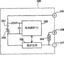
例如图7所示,移动电话机的电池组100具备:二次电池101;电池保护IC102及保护元件105,因过放电、过充电、过电流而保护二次电池101;PTC元件103,抑制短路电流;热敏电阻104,用来检测充电时的电池温度;等;其构成为,对于充电装置,要连接上连接端子106、107、108,并且一边由热敏电阻104监视电池温度,一边进行充电,对于负载装置(移动电话机),则连接上连接端子106、107将电池电力对负载装置进行放电。另外,就笔记本个人计算机的电池组而言,为了进行笔记本个人计算机的电源管理,所以一般采用在电池组和个人计算机主体之间通过双向2条总线连接的依照系统管理总线标准的智能电池系统等。For example, as shown in FIG. 7, the
另外,下述电池组已为众所周知,该电池组为了防止因连接于电池组不适合的充电装置上导致的故障或事故,以及防止因使用仿造电池组导致的故障或事故等,设置了ID存储机构,记录有用来确定可连接的电池组的识别信息。图8是表示下述电池组及其连接系统以往结构的附图,该电池组及其连接系统为了防止在负载装置上连接仿造电池组或在除适合的专用充电器之外的充电装置上连接电池组,在电池组200中设置ID电路部207,并在连接该电池组200的连接装置(负载装置或充电装置)300侧设置ID检测部307。In addition, the following battery packs are well known. In order to prevent failures or accidents caused by connection to an inappropriate charging device for the battery pack, and to prevent failures or accidents caused by the use of counterfeit battery packs, ID storage is provided. Mechanism, recorded with identification information for identifying connectable battery packs. Fig. 8 is a drawing showing a conventional structure of a battery pack and its connection system for preventing a counterfeit battery pack from being connected to a load device or a charging device other than a suitable dedicated charger. As for the battery pack, the ID circuit unit 207 is provided in the battery pack 200 , and the ID detection unit 307 is provided on the connection device (load device or charging device) 300 side to which the battery pack 200 is connected.
在图8中,电池组200的结构具备:二次电池201;温度检测机构202、电压检测机构203及电流检测机构204,分别检测该二次电池201的温度、电压及充放电电流;控制电路206,根据来自各检测机构的检测信息来检测二次电池201的过充电、过放电、过电流的状态,对保护元件205进行ON/OFF控制;ID电路部207,记录有识别信息;二次电池201的正极及负极分别连接到正极充放电端子208、负极充放电端子209上,上述ID电路部207连接到ID端子210上。另外,连接装置300在这里表示出充电装置,其结构具备:充电电源301;ID检测部307,从上述ID电路部207读出识别信息;条件选择部306,根据所读出的识别信息来判断电池组200的适合性,对来自上述充电电源301的充电电力输出进行控制。In FIG. 8 , the structure of the battery pack 200 includes: a secondary battery 201; a temperature detection mechanism 202, a voltage detection mechanism 203, and a current detection mechanism 204, respectively detecting the temperature, voltage and charge and discharge current of the secondary battery 201; a control circuit 206, detect the state of overcharge, overdischarge, and overcurrent of the secondary battery 201 according to the detection information from each detection mechanism, and perform ON/OFF control on the protection element 205; the ID circuit part 207 records identification information; The positive and negative electrodes of the battery 201 are connected to the positive charging and discharging terminal 208 and the negative charging and discharging terminal 209 , respectively, and the ID circuit unit 207 is connected to the ID terminal 210 . In addition, the connection device 300 here represents a charging device, and its structure includes: a charging power supply 301; an ID detection unit 307, which reads identification information from the above-mentioned ID circuit unit 207; a condition selection unit 306, which determines The suitability of the battery pack 200 is controlled by controlling the charging power output from the charging power source 301 described above.
无论上面所示例的电池组100、200,在电池组和充电装置或负载装置之间的连接中,除了正极及负极的直流电力传输线路之外,不可缺少的是,传输控制信息和ID信息等的信息传输线路的连接。也就是说,因为除了基本上必须的传输直流电力的2条线路连接之外,还存在信号传输线路,所以为了将电池组连接于连接装置上,需要3个以上的连接端子。连接端子的个数越多,越容易受到电磁波干扰(EMI:Electro Magnetic Interference)或静电破坏,有可能受到功能下降或错误动作、存储信息消失等的影响。另外,因为连接端子的大型化和布线连接的作业工时数,难以实现装置上的小型化,易于招致成本上升。Regardless of the
从而,优选的是连接端子的个数减少,并且理想的结构为,只有基本上必须的连接直流电力传输线路的2个连接端子。作为实现该结构的以往技术,下述结构已为众所周知,即在电池组和充电器之间的连接中将信息传输设为电磁连接或光学连接,并且作为连接端子只有直流电力传输所用的正极及负极2个充放电端子的结构(例如,参见专利文献1)。Therefore, it is preferable to reduce the number of connection terminals, and ideally, there are only two connection terminals that are basically necessary for connecting the DC power transmission line. As a conventional technology for realizing this structure, the following structure is well known, that is, the connection between the battery pack and the charger uses electromagnetic connection or optical connection for information transmission, and only the positive electrode and the positive electrode for DC power transmission are used as connection terminals. The structure of two charging and discharging terminals of the negative electrode (for example, refer to Patent Document 1).
专利文献1:日本特开平05-135804号公报Patent Document 1: Japanese Patent Application Laid-Open No. 05-135804
发明内容Contents of the invention
但是,上述以往技术其机械性连接的连接端子仅仅是正极及负极的2个充放电端子,而为了进行电磁或光学连接,需要在电池组和连接装置的对应位置上开设用来进行电磁耦合或光耦合的窗口,存在无法简单构成端子连接的课题。另外,因为用来进行电磁或光学连接的结构要件需要在电池组和充电装置或负载装置接近的部位上以指定的准确度相对配置,所以其课题为,限定于电池组和充电装置或负载装置能紧密配置的情形。再者,因为为了进行信息传输而配置于电池组及充电装置或负载装置中的结构要件位置被限定,配置空间有所增大,所以难以使用于便携式电子设备等小型的设备中。However, the connection terminals for mechanical connection in the above-mentioned prior art are only two charging and discharging terminals of the positive pole and the negative pole, and in order to perform electromagnetic or optical connection, it is necessary to open the corresponding positions of the battery pack and the connection device for electromagnetic coupling or There is a problem that the optical coupling window cannot be easily configured for terminal connection. In addition, because the structural elements for electromagnetic or optical connection need to be relatively arranged with a specified accuracy at the position where the battery pack and the charging device or the load device are close, the problem is limited to the battery pack and the charging device or the load device. Situations that can be tightly configured. Furthermore, since the position of the structural elements arranged in the battery pack, charging device, or load device for information transmission is limited, the arrangement space increases, so it is difficult to use it in small devices such as portable electronic devices.
因此,本发明的目的为,鉴于上述问题,提供一种利用直流电力传输线路来进行电池组和充电装置或负载装置之间的信息传输并且将端子连接只设为直流电力传输线路的2个连接端子的电池组及其连接系统。Therefore, an object of the present invention is to provide a DC power transmission line for information transmission between a battery pack and a charging device or a load device in view of the above-mentioned problems, and to provide terminal connections as only two connections of the DC power transmission line. Terminal battery pack and its connection system.
为了达到上述目的的本申请第1发明是一种电池组,具备二次电池和与其正极及负极分别连接的正极充放电端子及负极充放电端子,其特征为,具备:识别信息记录机构,记录有识别信息;信息信号发送机构,将从该识别信息记录机构所读出的识别信息,调制成可通过正极充放电端子或负极充放电端子传送给下述充电装置或负载装置的识别信号,进行发送,该充电装置连接于上述正极充放电端子及负极充放电端子上,给二次电池供应充电电力,该负载装置连接于正极充放电端子及负极充放电端子上,利用二次电池的放电电力进行动作。In order to achieve the above object, the first invention of the present application is a battery pack comprising a secondary battery, a positive charge-discharge terminal and a negative charge-discharge terminal respectively connected to the positive electrode and the negative electrode of the secondary battery, and is characterized in that it is provided with an identification information recording mechanism for recording There is identification information; the information signal transmission mechanism modulates the identification information read from the identification information recording mechanism into an identification signal that can be transmitted to the following charging device or load device through the positive charging and discharging terminal or the negative charging and discharging terminal Sending, the charging device is connected to the positive charge and discharge terminal and the negative charge and discharge terminal to supply charging power to the secondary battery, and the load device is connected to the positive charge and discharge terminal and the negative charge and discharge terminal to use the discharge power of the secondary battery Take action.
根据上述结构,电池组对充电装置或负载装置的连接只是作为直流电力传输线路的正极及负极2个电力连接端子间的连接,在将电池组连接于充电装置或负载装置上时可以从信息信号发送机构将识别信息通过上述电力连接端子发送给充电装置或负载装置。在充电装置或负载装置中,可以根据通过电力连接端子传输来的识别信息判定适合性,能够防止因连接不适合的电池组导致的故障或动作不佳的发生于未然。另外,由于连接只是2个端子连接,因而电磁波干扰和静电破坏的影响较少,可以防止破损或错误动作等的发生,并能够借助连接构造的简单化来谋求小型化、成本降低。According to the above structure, the connection of the battery pack to the charging device or the load device is only the connection between the positive pole and the negative pole of the DC power transmission line. When the battery pack is connected to the charging device or the load device, the information signal The sending mechanism sends the identification information to the charging device or the load device through the above-mentioned power connection terminal. In a charging device or a load device, the suitability can be determined based on the identification information transmitted through the power connection terminal, and it is possible to prevent malfunctions or malfunctions caused by connecting an unsuitable battery pack. In addition, since the connection is only two terminals, the influence of electromagnetic wave interference and electrostatic breakdown is small, and the occurrence of damage or malfunction can be prevented, and the simplification of the connection structure can achieve miniaturization and cost reduction.
另外,本申请第2发明是一种电池组,具备二次电池、与其正极及负极分别连接的正极充放电端子及负极充放电端子和检测上述二次电池动作状态的电池动作状态检测机构,其特征为,具备信息信号发送机构,将由上述电池动作状态检测机构检测出的动作状态检测信息,调制成可通过正极充放电端子或负极充放电端子传送给下述充电装置或负载装置的动作状态检测信号,进行发送,该充电装置连接于上述正极充放电端子及负极充放电端子上,给二次电池供应充电电力,该负载装置连接于正极充放电端子及负极充放电端子上,利用二次电池的放电电力进行动作。In addition, the second invention of the present application is a battery pack comprising a secondary battery, a positive charge-discharge terminal and a negative charge-discharge terminal respectively connected to the positive electrode and the negative electrode thereof, and a battery operating state detection mechanism for detecting the operating state of the secondary battery, wherein It is characterized in that an information signal transmission mechanism is provided, and the operation state detection information detected by the above-mentioned battery operation state detection mechanism is modulated to be transmitted to the following charging device or load device through the positive charge and discharge terminal or the negative charge and discharge terminal. The charging device is connected to the positive charge and discharge terminal and the negative charge and discharge terminal to supply charging power to the secondary battery. The load device is connected to the positive charge and discharge terminal and the negative charge and discharge terminal to use the secondary battery discharge power to operate.
根据上述结构,电池组对充电装置或负载装置的连接只是作为直流电力传输线路的正极及负极2个电力连接端子间的连接,在将电池组连接于充电装置或负载装置上时可以从信息信号发送机构将动作状态检测信息通过上述电力连接端子发送给充电装置或负载装置。在充电装置或负载装置中,可以根据通过电力连接端子传输来的动作状态检测信息判定电池组的动作状态,并能够检测异常发生等的不佳状况并迅速进行应对。另外,由于连接只是2个端子连接,因而电磁波干扰或静电破坏的影响较少,可以防止破损或错误动作的发生等,并能够借助连接构造的简单化来谋求小型化、成本降低。According to the above structure, the connection of the battery pack to the charging device or the load device is only the connection between the positive pole and the negative pole of the DC power transmission line. When the battery pack is connected to the charging device or the load device, the information signal The sending mechanism sends the operation state detection information to the charging device or the load device through the power connection terminal. In a charging device or a load device, the operating state of the battery pack can be determined based on the operating state detection information transmitted through the power connection terminal, and it is possible to detect and quickly respond to failures such as abnormalities. In addition, since the connection is only two terminals, the influence of electromagnetic wave interference or electrostatic breakdown is small, and the occurrence of damage or malfunction can be prevented, and the simplification of the connection structure can achieve miniaturization and cost reduction.
另外,本申请第3发明是一种电池组,具备二次电池、与其正极及负极分别连接的正极充放电端子及负极充放电端子和检测上述二次电池动作状态的电池动作状态检测机构,其特征为,具备:识别信息记录机构,记录有识别信息;信息信号发送机构,将从该识别信息记录机构所读出的识别信息或者由上述动作状态检测机构检测出的动作状态检测信息,调制成可通过正极充放电端子或负极充放电端子传送给下述充电装置或负载装置的信息信号,进行发送,该充电装置连接于上述正极充放电端子及负极充放电端子上,给二次电池供应充电电力,该负载装置连接于正极充放电端子及负极充放电端子上,利用二次电池的放电电力进行动作。In addition, the third invention of the present application is a battery pack comprising a secondary battery, a positive charge-discharge terminal and a negative charge-discharge terminal respectively connected to the positive electrode and the negative electrode thereof, and a battery operating state detection mechanism for detecting the operating state of the secondary battery, wherein It is characterized in that it has: an identification information recording mechanism that records identification information; an information signal transmission mechanism that modulates the identification information read from the identification information recording mechanism or the operation state detection information detected by the above operation state detection mechanism into The information signal can be transmitted to the following charging device or load device through the positive charging and discharging terminal or the negative charging and discharging terminal, and the charging device is connected to the above-mentioned positive charging and discharging terminal and the negative charging and discharging terminal to supply charging Electric power, the load device is connected to the positive charging and discharging terminal and the negative charging and discharging terminal, and operates by using the discharged power of the secondary battery.
根据上述结构,电池组对充电装置或负载装置的连接只是作为直流电力传输线路的正极及负极2个电力连接端子间的连接,可以从信息信号发送机构将识别信息及动作状态检测信息通过上述电力连接端子发送给充电装置或负载装置。在充电装置或负载装置中,可以根据通过上述电力连接端子传输来的识别信息判定适合性,能够防止因连接不适合的电池组导致的故障或动作不佳的发生于未然,并且可以根据动作状态检测信息判定电池组的动作状态,能够检测异常发生等的不佳状况并迅速进行应对。另外,由于连接只是2个端子连接,因而电磁波干扰或静电破坏的影响较少,可以防止破损或错误动作的发生等。According to the above structure, the connection of the battery pack to the charging device or the load device is only as the connection between the positive and negative power connection terminals of the DC power transmission line, and the identification information and operating state detection information can be transmitted from the information signal transmission mechanism through the above-mentioned electric power. The connection terminal is sent to the charging device or the load device. In the charging device or load device, the suitability can be determined based on the identification information transmitted through the above-mentioned power connection terminal, and it is possible to prevent failures or malfunctions caused by connecting an unsuitable battery pack from happening beforehand, and it can be used according to the operating state. The detection information determines the operating state of the battery pack, and it is possible to detect and quickly respond to failures such as abnormalities. In addition, since the connection is only two terminals, the influence of electromagnetic wave interference or static electricity damage is small, and the occurrence of damage or malfunction can be prevented.
另外,本申请第4发明是一种电池组,具备二次电池、与其正极及负极分别连接的正极充放电端子及负极充放电端子和检测上述二次电池动作状态的电池动作状态检测机构,其特征为,具备:识别信息记录机构,记录有识别信息;信息信号接收机构,对从充电装置或负载装置通过正极充放电端子或负极充放电端子传送来的询问信号进行解调,取出询问信息;信息信号发送机构,将按照上述询问信息中所记述的请求从上述识别信息记录机构所读出的识别信息或者由上述动作状态检测机构检测出的动作状态检测信息,调制成可通过正极充放电端子或负极充放电端子传送给下述充电装置或负载装置的信息信号,进行发送,该充电装置连接于上述正极充放电端子及负极充放电端子上,给二次电池供应充电电力,该负载装置连接于正极充放电端子及负极充放电端子上,利用二次电池的放电电力进行动作。In addition, a fourth invention of the present application is a battery pack comprising a secondary battery, a positive charge-discharge terminal and a negative charge-discharge terminal respectively connected to the positive electrode and the negative electrode of the secondary battery, and a battery operating state detection mechanism for detecting the operating state of the secondary battery. It is characterized in that it has: an identification information recording mechanism, which records identification information; an information signal receiving mechanism, which demodulates the inquiry signal transmitted from the charging device or the load device through the positive charge and discharge terminal or the negative charge and discharge terminal, and takes out the inquiry information; The information signal sending unit modulates the identification information read from the identification information recording unit or the operation state detection information detected by the operation state detection unit in accordance with the request described in the above inquiry information so that it can pass through the positive charging and discharging terminal. Or the negative charge and discharge terminal transmits information signals to the following charging device or load device. The charging device is connected to the above positive charge and discharge terminal and the negative charge and discharge terminal to supply charging power to the secondary battery. The load device is connected to On the positive charge and discharge terminal and the negative charge and discharge terminal, the discharge power of the secondary battery is used for operation.
根据上述结构,电池组对充电装置或负载装置的连接只是作为直流电力传输线路的正极及负极2个电力连接端子间的连接,可以按照由信息信号接收机构所接收到的来自充电装置或负载装置的请求,从信息信号发送机构通过上述电力连接端子发送与请求相对应的识别信息及动作状态检测信息。在充电装置或负载装置中,可以根据通过电力连接端子传输来的识别信息判定适合性,能够防止因连接不适合的电池组导致的故障或动作不佳的发生于未然,并且可以根据动作状态检测信息判定电池组的动作状态,能够检测异常发生等的不佳状况并迅速进行应对。另外,由于连接只是2个端子连接,因而电磁波干扰或静电破坏的影响较少,可以防止破损或错误动作的发生等。According to the above-mentioned structure, the connection of the battery pack to the charging device or the load device is only as the connection between the positive pole and the negative pole of the DC power transmission line, and can be received according to the information received by the information signal receiving mechanism from the charging device or load device. request, the identification information and operating state detection information corresponding to the request are transmitted from the information signal transmission mechanism through the above-mentioned power connection terminal. In the charging device or load device, the suitability can be determined based on the identification information transmitted through the power connection terminal, which can prevent failures or malfunctions caused by connecting unsuitable battery packs, and can detect The information determines the operating status of the battery pack, and it is possible to detect abnormalities such as abnormalities and respond quickly. In addition, since the connection is only two terminals, the influence of electromagnetic wave interference or static electricity damage is small, and the occurrence of damage or malfunction can be prevented.
因为上述各结构中电池组和充电装置或负载装置之间的电连接仅仅是正极及负极2个连接端子间的连接,所以并不只是电池组和充电装置或负载装置之间的电连接较为简单且可以小型化,还较少受到经信息传输线路的电磁波干扰,也不易受到静电破坏的影响。Because the electrical connection between the battery pack and the charging device or the load device in the above structures is only the connection between the two connection terminals of the positive pole and the negative pole, it is not only the electrical connection between the battery pack and the charging device or the load device that is relatively simple. And it can be miniaturized, and it is less affected by electromagnetic wave interference through the information transmission line, and is not easily affected by static electricity damage.
另外,由于其构成为,上述各电池组中的信息信号发送机构根据识别信息或动作状态检测信息,作为采用指定的调制方法调制指定频率的载波后的识别信号或动作状态检测信号,在直流电力传输线路上进行传送及发送,因而能够实现经直流电力传输线路的信息传输,可以利用2个端子连接来进行电池组和充电装置或负载装置之间的连接。In addition, since it is constructed such that the information signal transmission mechanism in each of the above-mentioned battery packs uses the identification information or the operating state detection information as an identification signal or an operating state detection signal obtained by modulating a carrier wave of a specified frequency by a specified modulation method, the DC power Transmission and transmission are carried out on the transmission line, so information transmission via the DC power transmission line can be realized, and the connection between the battery pack and the charging device or load device can be performed by using two terminal connections.
另外,由于其构成为,信息信号发送机构根据识别信息或动作状态检测信息,对在正极充放电端子或负极充放电端子上流动的充电电流进行脉冲调制,因而可以通过使充放电电流断续的脉冲调制,在直流电力传输线路中重叠信息信号。从而,能够实现经直流电力传输线路的信息传输,可以利用2个端子连接来进行电池组和充电装置或负载装置之间的连接。In addition, since it is configured such that the information signal transmitting mechanism pulse-modulates the charging current flowing through the positive charging and discharging terminal or the negative charging and discharging terminal based on the identification information or the operating state detection information, it is possible to make the charging and discharging current intermittent. Pulse modulation, superimposing information signals in DC power transmission lines. Accordingly, information transmission via the DC power transmission line can be realized, and the connection between the battery pack and the charging device or load device can be performed using two terminal connections.
另外,本申请第5发明是一种电池组的连接系统,将下述电池组连接于下述充电装置或负载装置上,该电池组具备二次电池和与其正极及负极分别连接的正极充放电端子及负极充放电端子,该充电装置连接于上述正极充放电端子及负极充放电端子上,给二次电池供应充电电力,该负载装置连接于正极充放电端子及负极充放电端子上,利用二次电池的放电电力进行动作,其特征为,上述电池组具备:识别信息记录机构,记录有识别信息;信息信号发送机构,将从上述识别信息记录机构所读出的识别信息,调制成可通过上述正极充放电端子或负极充放电端子传送给上述充电装置或负载装置的信息信号,进行发送;上述充电装置或负载装置具备:信息信号接收机构,对通过上述正极充放电端子或负极充放电端子传送来的上述信息信号进行解调,读出识别信息;电源控制机构,分析所读出的识别信息,来控制充电装置的充电电力输出或对负载装置的放电电力输入。In addition, the fifth invention of the present application is a connection system of a battery pack, which connects the following battery pack to the following charging device or load device. terminal and negative charging and discharging terminal, the charging device is connected to the positive charging and discharging terminal and the negative charging and discharging terminal to supply charging power to the secondary battery, the load device is connected to the positive charging and discharging terminal and the negative charging and discharging terminal, using two The discharge power of the secondary battery operates, and it is characterized in that the above-mentioned battery pack includes: an identification information recording mechanism that records identification information; and an information signal transmission mechanism that modulates the identification information read from the identification information recording mechanism to be passed The above-mentioned positive charge and discharge terminal or the negative charge and discharge terminal transmits the information signal transmitted to the above-mentioned charging device or load device; The transmitted information signal is demodulated to read the identification information; the power control mechanism analyzes the read identification information to control the charging power output of the charging device or the discharging power input to the load device.
根据上述结构,电池组和充电装置或负载装置之间的连接只是作为直流电力传输线路的正极及负极2个电力连接端子间的连接,在将电池组连接于充电装置或负载装置上时可以从信息信号发送机构将识别信息通过上述电力连接端子发送给充电装置或负载装置。充电装置或负载装置可以利用信息信号接收机构对通过电力连接端子传输来的识别信号进行解调,取出识别信息。充电装置或负载装置可以根据识别信息判定电池组的适合性,能够防止因连接不适合的电池组导致的故障或动作不佳的发生于未然。另外,由于连接只是2个端子连接,因而电磁波干扰或静电破坏的影响较少,可以防止破损或错误动作的发生等,并能够借助连接构造的简单化来谋求小型化、成本降低。According to the above structure, the connection between the battery pack and the charging device or the load device is only the connection between the positive pole and the negative pole of the DC power transmission line. When the battery pack is connected to the charging device or the load device, it can be connected from The information signal sending mechanism sends the identification information to the charging device or the load device through the above-mentioned power connection terminal. The charging device or the load device can use the information signal receiving mechanism to demodulate the identification signal transmitted through the power connection terminal to extract the identification information. The charging device or the load device can determine the suitability of the battery pack based on the identification information, and can prevent malfunctions or malfunctions caused by connecting an unsuitable battery pack. In addition, since the connection is only two terminals, the influence of electromagnetic wave interference or electrostatic breakdown is small, and the occurrence of damage or malfunction can be prevented, and the simplification of the connection structure can achieve miniaturization and cost reduction.
另外,本申请第6发明是一种电池组的连接系统,将下述电池组连接于下述充电装置或负载装置上,该电池组具备二次电池、与其正极及负极分别连接的正极充放电端子及负极充放电端子和检测上述二次电池动作状态的电池动作状态检测机构,该充电装置连接于上述正极充放电端子及负极充放电端子上,给二次电池供应充电电力,该负载装置连接于正极充放电端子及负极充放电端子上,利用二次电池的放电电力进行动作,其特征为,上述电池组具备信息信号发送机构,将由上述电池动作状态检测机构检测出的动作状态检测信息,调制成可通过正极充放电端子或负极充放电端子传送给连接于上述正极充放电端子或负极充放电端子上的上述充电装置或负载装置的动作状态检测信号,进行发送;上述充电装置或负载装置具备:信息信号接收机构,对通过上述正极充放电端子或负极充放电端子传送来的上述信息信号进行解调,读出动作状态检测信息;电源控制机构,根据所读出的动作状态检测信息,来控制充电装置的充电电力输出或对负载装置的放电电力输入。In addition, the sixth invention of the present application is a connection system of a battery pack, which connects the following battery pack to the following charging device or load device. terminals, negative charging and discharging terminals, and a battery operating state detection mechanism for detecting the operating state of the above-mentioned secondary battery. The charging device is connected to the above-mentioned positive charging and discharging terminal and negative charging and discharging terminal to supply charging power to the secondary battery. On the positive charge and discharge terminal and the negative charge and discharge terminal, the discharge power of the secondary battery is used for operation, and it is characterized in that the above-mentioned battery pack is equipped with an information signal transmission mechanism, and the operation state detection information detected by the above-mentioned battery operation state detection mechanism is It is modulated so that it can be transmitted to the above-mentioned charging device or load device connected to the above-mentioned positive charge-discharge terminal or negative charge-discharge terminal through the positive charge-discharge terminal or the negative charge-discharge terminal. Equipped with: an information signal receiving mechanism, which demodulates the above-mentioned information signal transmitted through the above-mentioned positive charge-discharge terminal or negative charge-discharge terminal, and reads out the operation state detection information; the power control mechanism, based on the read-out operation state detection information, To control the charging power output of the charging device or the discharging power input to the load device.
根据上述结构,电池组和充电装置或负载装置之间的连接只是作为直流电力传输线路的正极及负极2个电力连接端子间的连接,可以从信息信号发送机构将电池组的动作状态检测信息通过上述电力连接端子发送给充电装置或负载装置。在充电装置或负载装置中,可以根据通过电力连接端子传输来的动作状态检测信息,判定电池组的动作状态,检测异常发生等的不佳状况并迅速进行应对。另外,由于连接只是2个端子连接,因而电磁波干扰或静电破坏的影响较少,可以防止破损或错误动作的发生等,能够借助连接构造的简单化来谋求小型化、成本降低。According to the above structure, the connection between the battery pack and the charging device or the load device is only the connection between the positive and negative power connection terminals of the DC power transmission line, and the operating state detection information of the battery pack can be transmitted from the information signal transmission mechanism. The above-mentioned power connection terminal is sent to a charging device or a load device. In a charging device or a load device, it is possible to determine the operating state of the battery pack based on the operating state detection information transmitted through the power connection terminal, detect abnormalities such as occurrences, and respond promptly. In addition, since the connection is only two terminals, the influence of electromagnetic wave interference or electrostatic breakdown is small, and the occurrence of damage or malfunction can be prevented, and the simplification of the connection structure can achieve miniaturization and cost reduction.
另外,本申请第7发明是一种电池组的连接系统,将下述电池组连接于下述充电装置或负载装置上,该电池组具备二次电池、与其正极及负极分别连接的正极充放电端子及负极充放电端子和检测上述二次电池动作状态的电池动作状态检测机构,该充电装置连接于上述正极充放电端子及负极充放电端子上,给二次电池供应充电电力,该负载装置连接于正极充放电端子及负极充放电端子上,利用二次电池的放电电力进行动作,其特征为,上述电池组具备:识别信息记录机构,记录有识别信息;信息信号发送机构,将从该识别信息记录机构所读出的识别信息或者由上述电池动作状态检测机构检测出的动作状态检测信息,调制成可通过上述正极充放电端子或负极充放电端子传送给上述充电装置或负载装置的信息信号,进行发送;上述充电装置或负载装置具备:信息信号接收机构,对通过上述正极充放电端子或负极充放电端子传送来的上述信息信号进行解调,读出识别信息或动作状态检测信息;电源控制机构,根据所读出的识别信息或动作状态检测信息,来控制充电装置的充电电力输出或对负载装置的放电电力输入。In addition, the seventh invention of the present application is a connection system of a battery pack, which connects the following battery pack to the following charging device or load device. terminals, negative charging and discharging terminals, and a battery operating state detection mechanism for detecting the operating state of the above-mentioned secondary battery. The charging device is connected to the above-mentioned positive charging and discharging terminal and negative charging and discharging terminal to supply charging power to the secondary battery. On the positive charging and discharging terminal and the negative charging and discharging terminal, the discharge power of the secondary battery is used for operation. It is characterized in that the battery pack is equipped with: an identification information recording mechanism that records identification information; The identification information read by the information recording mechanism or the operation state detection information detected by the above-mentioned battery operation state detection mechanism is modulated into an information signal that can be transmitted to the above-mentioned charging device or load device through the above-mentioned positive charging and discharging terminal or negative charging and discharging terminal , to send; the above-mentioned charging device or load device has: an information signal receiving mechanism, which demodulates the above-mentioned information signal transmitted through the above-mentioned positive charging and discharging terminal or negative charging and discharging terminal, and reads identification information or operation state detection information; The control means controls the charging power output from the charging device or the discharging power input to the load device based on the read identification information or operating state detection information.
根据上述结构,电池组和充电装置或负载装置之间的连接只是作为直流电力传输线路的正极及负极2个电力连接端子间的连接,可以从信息信号发送机构将识别信息及动作状态检测信息通过上述电力连接端子发送给充电装置或负载装置。在充电装置或负载装置中,可以根据通过电力连接端子传输来的识别信息判定适合性,能够防止因连接不适合的电池组导致的故障或动作不佳的发生于未然,并且可以根据动作状态检测信息判定电池组的动作状态,能够检测异常发生等的不佳状况并迅速进行应对。另外,由于连接只是2个端子连接,因而电磁波干扰或静电破坏的影响较少,可以防止破损或错误动作的发生等。According to the above structure, the connection between the battery pack and the charging device or the load device is only the connection between the positive and negative power connection terminals of the DC power transmission line, and the identification information and operating state detection information can be transmitted from the information signal transmission mechanism. The above-mentioned power connection terminal is sent to a charging device or a load device. In the charging device or load device, the suitability can be determined based on the identification information transmitted through the power connection terminal, which can prevent failures or malfunctions caused by connecting unsuitable battery packs, and can detect The information determines the operating status of the battery pack, and it is possible to detect abnormalities such as abnormalities and respond quickly. In addition, since the connection is only two terminals, the influence of electromagnetic wave interference or static electricity damage is small, and the occurrence of damage or malfunction can be prevented.
另外,本申请第8发明是一种电池组的连接系统,将下述电池组连接于下述充电装置或负载装置上,该电池组具备二次电池、与其正极及负极分别连接的正极充放电端子及负极充放电端子和检测上述二次电池动作状态的电池动作状态检测机构,该充电装置连接于上述正极充放电端子及负极充放电端子上,给二次电池供应充电电力,该负载装置连接于正极充放电端子及负极充放电端子上,利用二次电池的放电电力进行动作,其特征为,上述电池组具备:识别信息记录机构,记录有识别信息;信息信号接收机构,对从上述充电装置或负载装置通过上述正极充放电端子或负极充放电端子发送来的询问信号进行解调,取出询问信息;信息信号发送机构,调制按照上述询问信息中所记述的请求从上述识别信息记录机构所读出的识别信息或者由上述电池动作状态检测机构检测出的动作状态检测信息,作为响应信号通过上述正极充放电端子或负极充放电端子进行发送;上述充电装置或负载装置具备:信息信号发送机构,对询问信息进行调制,将其变成可通过上述正极充放电端子或负极充放电端子传送的询问信号,发送给所连接的电池组;信息信号接收机构,对通过正极充放电端子及负极充放电端子从电池组传送来的上述响应信号进行解调,读出识别信息或动作状态检测信息;电源控制机构,分析所读出的识别信息或动作状态检测信息,来控制充电装置的充电电力输出或对负载装置的放电电力输入。In addition, the eighth invention of the present application is a connection system of a battery pack, which connects the following battery pack to the following charging device or load device. terminals, negative charging and discharging terminals, and a battery operating state detection mechanism for detecting the operating state of the above-mentioned secondary battery. The charging device is connected to the above-mentioned positive charging and discharging terminal and negative charging and discharging terminal to supply charging power to the secondary battery. On the positive charge and discharge terminal and the negative charge and discharge terminal, the discharge power of the secondary battery is used for operation. It is characterized in that the battery pack is equipped with: an identification information recording mechanism that records identification information; The device or the load device demodulates the inquiry signal sent by the above-mentioned positive charging and discharging terminal or the negative charging and discharging terminal, and takes out the inquiry information; The read identification information or the operation state detection information detected by the above-mentioned battery operation state detection mechanism is sent as a response signal through the above-mentioned positive charging and discharging terminal or negative charging and discharging terminal; the above-mentioned charging device or load device has: an information signal sending mechanism , modulate the inquiry information, turn it into an inquiry signal that can be transmitted through the above-mentioned positive charging and discharging terminal or negative charging and discharging terminal, and send it to the connected battery pack; The discharge terminal demodulates the above-mentioned response signal transmitted from the battery pack, and reads the identification information or action state detection information; the power control mechanism analyzes the read identification information or action state detection information to control the charging power output of the charging device Or the discharge power input to the load device.
根据上述结构,电池组和充电装置或负载装置之间的连接只是作为直流电力传输线路的正极及负极2个电力连接端子间的连接,对于所连接的电池组,充电装置或负载装置可以从信息信号发送机构将必要的请求作为询问信号发送给电池组。若在连接了电池组时作为询问信号发出了用来识别电池组品种的识别信息的响应请求,则在接收到询问信号的电池组中,由信息信号接收机构对询问信号进行解调并取出询问信息,按照询问信息的请求从信息信号发送机构将识别信息通过上述电力连接端子发送给充电装置或负载装置。由于充电装置或负载装置可以利用信息信号接收机构对通过电力连接端子传输来的识别信号进行解调并取出识别信息,因而充电装置或负载装置可以根据识别信息判定电池组的适合性,能够防止因连接不适合的电池组导致的故障或动作不佳的发生于未然。由于该电池组的确定为利用双向通信的识别处理,因而能够谋求识别水平的高水准化。另外,充电装置或负载装置可以根据需要,将与电池组的动作状态有关的请求从信息信号发送机构作为询问信号发送给电池组。电池组在接收到询问信号时,由信息信号接收机构对询问信号进行解调并取出询问信息,按照询问信息的请求从信息信号发送机构作为下述动作状态检测信号,通过上述电力连接端子发送给充电装置或负载装置,该动作状态检测信号是调制由电池动作状态检测机构检测出的动作状态检测信息后的信号。由于充电装置或负载装置可以利用信息信号接收机构对通过电力连接端子传输来的动作状态检测信号进行解调并取出动作状态检测信息,因而充电装置或负载装置可以根据动作状态检测信息判明电池组的动作状态,能够实施与电池组的动作状态相对应的控制。由于该电池组的动作状态检测为利用双向通信的处理,因而充电装置或负载装置可以根据需要获得必要的动作状态信息。另外,由于进行双向通信所需的连接只是直流电力传输线路的2个端子连接,因而电磁波干扰或静电破坏的影响较少,可以防止破损或错误动作的发生等,能够借助连接构造的简单化来谋求小型化、成本下降。According to the above structure, the connection between the battery pack and the charging device or the load device is only the connection between the positive pole and the negative pole of the DC power transmission line. For the connected battery pack, the charging device or the load device can obtain information from The signaling mechanism sends the necessary request as an interrogation signal to the battery pack. If a response request for identification information for identifying the type of the battery pack is sent as an inquiry signal when the battery pack is connected, in the battery pack that has received the inquiry signal, the information signal receiving mechanism demodulates the inquiry signal and takes out the inquiry signal. For information, the identification information is transmitted from the information signal transmission mechanism to the charging device or the load device through the above-mentioned power connection terminal according to the request of the inquiry information. Since the charging device or load device can use the information signal receiving mechanism to demodulate the identification signal transmitted through the power connection terminal and take out the identification information, the charging device or load device can judge the suitability of the battery pack based on the identification information, which can prevent Malfunctions or malfunctions caused by connecting an inappropriate battery pack will occur before they occur. Since the identification of the battery pack is an identification process using two-way communication, it is possible to achieve a high level of identification. In addition, the charging device or the load device may transmit a request related to the operating state of the battery pack from the information signal transmission means to the battery pack as an inquiry signal as necessary. When the battery pack receives the inquiry signal, the information signal receiving unit demodulates the inquiry signal and takes out the inquiry information. According to the request of the inquiry information, the information signal sending unit sends the following operating state detection signal through the above-mentioned power connection terminal to In the charging device or the load device, the operation state detection signal is a signal obtained by modulating the operation state detection information detected by the battery operation state detection means. Since the charging device or the load device can use the information signal receiving mechanism to demodulate the operation state detection signal transmitted through the power connection terminal and take out the operation state detection information, the charging device or the load device can judge the status of the battery pack according to the operation state detection information. The operating state can be controlled according to the operating state of the battery pack. Since the detection of the operating state of the battery pack is processed by bidirectional communication, the charging device or the load device can obtain necessary operating state information as necessary. In addition, since the connection required for two-way communication is only two terminal connections of the DC power transmission line, the influence of electromagnetic wave interference or electrostatic damage is small, and damage or malfunction can be prevented, and the connection structure can be simplified. Seeking miniaturization and cost reduction.
由于其构成为,上述各连接系统中的信息信号发送机构根据识别信息或动作状态检测信息或者询问信息,作为采用指定的调制方法调制指定频率的载波后的识别信号或动作状态检测信号或者询问信号,通过直流电力传输线路进行发送,因而能够实现经直流电力传输线路的信息传输,可以利用2个端子连接来进行电池组和充电装置或负载装置之间的连接。Because of its structure, the information signal transmission mechanism in each of the above-mentioned connection systems uses the identification information or the operation state detection information or the inquiry information as the identification signal or the operation state detection signal or the inquiry signal after the carrier wave of the specified frequency is modulated by the specified modulation method. , Send through the DC power transmission line, so that the information transmission through the DC power transmission line can be realized, and the connection between the battery pack and the charging device or the load device can be performed by using two terminal connections.
另外,由于其构成为,信息信号发送机构根据识别信息或动作状态检测信息或者询问信息,对在直流电力传输线路上流动的充放电电流进行脉冲调制,因而可以通过充放电电流的脉冲调制在直流电力传输线路中重叠信息信号。从而,能够实现经直流电力传输线路的信息传输,可以利用2个端子连接来进行电池组和充电装置或负载装置之间的连接。In addition, since it is configured such that the information signal transmitting mechanism pulse-modulates the charging and discharging current flowing on the DC power transmission line based on the identification information or the operating state detection information or the inquiry information, it is possible to generate electricity in the DC power through the pulse modulation of the charging and discharging current. Overlapping information signals in transmission lines. Accordingly, information transmission via the DC power transmission line can be realized, and the connection between the battery pack and the charging device or load device can be performed using two terminal connections.
另外,由于其构成为,各连接系统中的信息信号接收机构采用指定的解调方法对通过直流电力传输线路传送来的识别信号或动作状态检测信号或者询问信号进行解调,作为识别信息或动作状态检测信息或者询问信息将其取出,因而能够实现经直流电力传输线路的信息传输,可以利用过2个端子连接来进行电池组和充电装置或负载装置之间的连接。In addition, because of its structure, the information signal receiving mechanism in each connection system demodulates the identification signal or operation state detection signal or inquiry signal transmitted through the DC power transmission line using a specified demodulation method, as identification information or action The status detection information or query information is taken out, so that the information transmission through the DC power transmission line can be realized, and the connection between the battery pack and the charging device or the load device can be performed by using two terminal connections.
另外,由于信息信号接收机构设为下述脉冲解调来构成,该脉冲解调取出在直流电力传输线路上流动的脉冲调制后的充放电电流的电流变化,因而可以通过充放电电流的脉冲调制在直流电力传输线路中重叠信息信号。从而,能够实现经直流电力传输线路的信息传输,可以利用2个端子连接来进行电池组和充电装置或负载装置之间的连接。In addition, since the information signal receiving means is configured as a pulse demodulation that extracts the current change of the pulse-modulated charging and discharging current flowing in the DC power transmission line, it can be adjusted by pulse modulation of the charging and discharging current. Overlapping information signals in DC power transmission lines. Accordingly, information transmission via the DC power transmission line can be realized, and the connection between the battery pack and the charging device or load device can be performed using two terminal connections.
附图的简单说明A brief description of the drawings
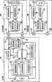
图1是表示第1实施方式所涉及的电池组和其连接系统结构的框图;1 is a block diagram showing the structure of a battery pack and its connection system according to the first embodiment;
图2是表示将同上的连接系统使用于个人计算机时的结构的框图;Fig. 2 is a block diagram showing the structure when the same connection system is used in a personal computer;
图3是表示第2实施方式所涉及的使用直流电力传输线路的信号传输结构例的框图;3 is a block diagram showing an example of a signal transmission configuration using a DC power transmission line according to a second embodiment;
图4A~图4B是表示同上的结构变形例的框图;4A to 4B are block diagrams showing structural modifications of the same as above;
图5A是在充电装置的情况下表示对充放电电流进行脉宽调制的信息传输变化的图,图5B是在负载装置的情况下表示对充放电电流进行脉宽调制的信息传输变化的图;5A is a diagram showing changes in information transmission of pulse width modulation of charging and discharging currents in the case of a charging device, and FIG. 5B is a diagram showing changes in information transmissions of pulse width modulations of charging and discharging currents in the case of a load device;
图6是表示第3实施方式所涉及的电池组和其连接系统结构的框图;6 is a block diagram showing the structure of the battery pack and its connection system according to the third embodiment;
图7是表示在移动电话机中使用的以往例电池组结构的框图;7 is a block diagram showing the structure of a conventional battery pack used in a mobile phone;
图8是表示具备识别功能的以往例电池组结构的框图。FIG. 8 is a block diagram showing the configuration of a conventional battery pack provided with an identification function.
具体实施方式Detailed ways
下面,参照附图,对于将本发明具体化后的实施方式进行说明。还有,本实施方式是将本发明具体化的一例,并不用来限定本发明的技术范围。Hereinafter, specific embodiments of the present invention will be described with reference to the drawings. In addition, this embodiment is an example which actualized this invention, and does not limit the technical scope of this invention.
图1是表示本发明第1实施方式所涉及的由电池组1和与之连接的充电装置20及负载装置30构成的电池组连接系统的附图。电池组1在对二次电池2进行充电时,通过在充电装置20的正极充电端子21上连接正极充放电端子11,并在负极充电端子22上连接负极充放电端子12,利用从充电装置20供应的充电电力对二次电池22进行充电。另外,在与利用来自电池组1的放电电力进行动作的负载装置30进行连接时,通过在负载装置30的正极放电端子31上连接正极充放电端子11,并在负极放电端子32上连接负极充放电端子12,利用来自二次电池2的放电电力,使负载装置30进行动作。FIG. 1 is a diagram showing a battery pack connection system including a battery pack 1 and a charging
上述电池组1具备电池保护电路来构成,输入来自下述电池动作状态检测机构10的动作状态检测信息的控制机构3从动作状态检测信息检测二次电池2的过放电状态、过充电状态及过电流状态,在检测到它们时由保护元件(FET)6将充放电电路切断来保护二次电池2,上述电池动作状态检测机构10具备检测电池温度的温度检测机构7、检测电池电压的电压检测机构8以及检测充放电电流的电流检测机构9。另外,在电池组1中设置识别功能,确定该电池组1对应的充电装置20及负载装置30。电池组1需要在恰当控制适应二次电池2的电压及电流、温度各充电条件的状态下进行充电,为了防止与不对应的充电器连接时故障或事故的发生,其构成为可以确定对应的充电器,这里是充电装置20,再者还需要确定适合的负载装置30,以利用恰当的放电电力使负载装置30进行动作,不因不恰当的放电电力或不充分的电源控制而在负载装置30中发生故障或动作不佳。上述识别功能通过具备下述识别信息记录机构4和调制电路(信息信号发送机构)5来发挥作用,该识别信息记录机构4存储有确定设备种类的识别信息,该调制电路5将从该识别信息存储机构4所读出的识别信息调制成可重叠于直流电力传输线路中进行发送的识别信号。从识别信息记录机构4输入识别信息的控制机构3根据需要,将识别信息输入调制电路5。由于调制电路5使采用下述调制方法按识别信息调制后的识别信号重叠于直流电力传输线路中,因而通过直流电力传输线路,向充电装置20或负载装置30传送识别信号。还有,这里虽然识别信息记录机构4设为存储ID号码的存储器,但是也可以简单而言是具有特定电阻值的电阻器,或者复杂而言是存储特定信号或加密信号的存储器,并且可以按照识别准确度或分析准确度的水平实现最佳的结构。The aforementioned battery pack 1 is configured with a battery protection circuit, and the control unit 3 that receives operating state detection information from the battery operating
在将成为上述结构的电池组1与充电装置20进行连接时,把正极充放电端子11连接于充电装置20的正极充电端子21上,并把负极充放电端子12连接于充电装置20的负极充电端子22上,形成来自充电装置20的充电电流向电池组1流动的直流电力传输线路。由于在该连接开始时,控制机构3从识别信息记录机构4读出识别信息将其输入调制电路5,因而调制电路5根据识别信息,将采用下述的调制方法调制识别信息后的识别信号,通过正极充放电端子11、正极充电端子21发送给充电装置20。When connecting the battery pack 1 with the above-mentioned structure to the charging
充电装置20的结构具备:充电电源23,连接于正极充电端子21和负极充电端子22上;解调电路(信息信号接收机构)24,连接于正极充电端子21上,取出通过直流电力传输线路发送来的识别信号,将其解调为识别信息;电源控制机构25,判断从解调电路24输出的识别信息正确与否,通过电源管理机构26来控制上述充电电源23的输出。若连接了电池组1,则上述解调电路24对发送来的识别信号进行解调并取出识别信息,将其输入电源控制机构25。电源控制机构25判断传输来的识别信息是否正确,在识别信息正确时,由于通过电源管理机构26允许来自充电电源23的充电电力输出,因而对电池组1供应充电电力。另一方面,在识别信息不正确时,由于通过来自电源控制机构25的控制,电源管理机构26不允许来自充电电源23的输出,因而电池组1判断出双方不对应,不开始充电。从而,在对电池组1连接了双方不对应的充电器时不进行充电,防止因连接不合适的充电器导致的故障发生。The structure of the charging
另外,在将成为上述结构的电池组1与负载装置30进行连接时,把正极充放电端子11连接于负载装置的正极放电端子31上,并把负极充放电端子12连接于负载装置30的负极放电端子32上,形成来自电池组1的放电电流向负载装置30流动的直流电力传输线路。由于在该连接开始时,控制机构3从识别信息记录机构4读出识别信息,将其输入调制电路5,因而调制电路5将调制信息作为调制后的识别信号,通过正极充放电端子11、正极放电端子31发送给负载装置30。In addition, when connecting the battery pack 1 having the above-mentioned structure to the
负载装置30在识别信息的处理中和充电装置20相同来构成,其结构具备:负载33,连接于正极放电端子31和负极放电端子32上;解调电路(信息信号接收机构)34,连接于正极放电端子31上,取出通过直流电力传输线路发送来的识别信号,将其解调成识别信息;电源控制机构35,判断从解调电路34输出的识别信息正确与否,控制对上述负载33的电力供应;电源管理机构36,管理对负载33的电力供应。若连接了电池组1,则上述解调电路34对发送来的识别信号进行解调,取出识别信息将其输入电源控制机构35。电源控制机构35判断传输来的识别信息是否正确,在识别信息正确时,由于向电源管理机构36输出电力供应允许信号,电源管理机构36允许对负载33的放电电力供应,因而给负载33供应来自电池组1的放电电力,使负载装置30进行动作。在识别信息不正确时,由于电源控制机构35不向电源管理机构36输出电力供应允许信号,因而判断出所连接的电池组1双方不对应,无法使负载33进行动作。从而,在负载装置30上连接了双方不对应的电池电源时,负载装置30不进行动作,防止因连接不适合的电池电源导致的故障发生或动作不佳发生。The
就上述电池组1和将其连接于充电装置20或负载装置30上的连接系统而言,虽然将充电装置20和负载装置30设为单个个体,但是在移动电话机或笔记本个人计算机等方面,充电装置20和负载装置30也可以考虑为一个整体。Regarding the above-mentioned battery pack 1 and the connection system for connecting it to the charging
图2是表示笔记本个人计算机40的电源电路结构例的附图,一般来说AC适配器43作为笔记本个人计算机40的附带装置,成为电池组1充电时或能使用AC电源的使用状态下的直流电力供应源。从而,分别设置于充电装置20及负载装置30中的接收识别信息的结构可以作为解调电路(信息信号接收机构)44、电源控制机构45及电源管理机构46,进行通用化。还有,电源管理机构46在笔记本个人计算机40中,是用来对电池电源和AC电源进行转换控制的现有结构。2 is a diagram showing an example of the configuration of the power supply circuit of the notebook
在成为上述结构的笔记本个人计算机40的情况下,由于在把正极充放电端子11连接于笔记本个人计算机40的正极电源端子41上并将负极充放电端子12连接于负极电源端子42上,将电池组1安装到个人计算机40中时,从调制电路5通过正极充放电端子11、正极电源端子41给笔记本个人计算机40发送识别信号,因而笔记本个人计算机40通过解调电路44对识别信号进行解调,取出识别信息,将其输入电源控制机构45。电源控制机构45判断识别信息的正确与否,由于在识别信息正确时向电源管理机构46输出连接允许信号,因而电源管理机构46允许电池组1的连接。从而,能够从识别信息识别正常的电池组1并进行电池组1的充放电,在连接了识别信息不正确的仿造品等时不进行充放电,防止因连接不适合的电池组1导致的故障或动作不佳的发生。In the case of the notebook
如同上面作为本发明的背景技术之一在图7中所示的移动电话机电池组的示例那样,在将电池组100连接于充电装置上进行二次电池101的充电时,至少检测电池温度,做出与二次电池101的状态相对应的充电控制。从而,电池组100和充电装置之间的连接除了正极端子106及负极端子107的直流电力传输线路之外,还需要用来检测电池温度的温度检测端子108的连接,至少成为3个端子上的连接。另外,在像笔记本个人计算机40中的智能电池系统那样通过通信总线进行信息传输时,至少需要4个端子的连接。由于这种连接端子个数的增加如上所述,易于受到电磁波干扰或静电破坏的影响,并且招致成本上升等,因而是非优选的。Like the example of the mobile phone battery pack shown in FIG. 7 as one of the background technologies of the present invention, when the
采用本实施方式所涉及的结构,只通过正极及负极的直流电力传输线路的连接端子连接,除了直流电力的传输之外还能够实现信息的传输。另外,不仅仅是上述识别信息的传输,还可以只通过正极及负极的各充放电端子11、12的2个连接,将电池动作状态的信息发送给充电装置20或负载装置30。According to the structure according to the present embodiment, only by connecting the connection terminals of the positive and negative DC power transmission lines, it is possible to realize the transmission of information in addition to the transmission of DC power. In addition, not only the above-mentioned transmission of the identification information, but also the information of the battery operation state can be transmitted to the charging
如图1所示,由于给电池组1中所设置的控制机构3,从电池动作状态检测机构10输入了电池温度、电池电压及充放电电流的检测信息,因而可以从控制机构3将动作状态检测信息输出给调制电路5。输入动作状态检测信息后的调制电路5若将动作状态检测信息采用下述的调制方法调制成可重叠于直流电力传输线路中的动作状态检测信号,则可以在直流电力传输线路上传送,把动作状态检测信号发送给充电装置20或负载装置30。在充电装置20中,从在直流电力传输线路上传送而发送来的动作状态检测信号,通过解调电路24取出充电控制所需要的动作状态检测信息,根据动作状态检测信息由电源控制机构25对电源管理机构26进行控制,以此可以将与二次电池2的动作状态相对应的充电电压及充电电流所控制的充电电力,供应给电池组1。另外,由于电池组1的控制机构3监视着充电状态及放电状态,因而若将表示过充电状态或异常现象发生的信息,从电池组传送给充电装置20,则可以在充电装置20中执行使充电停止的控制。另外,在负载装置30是笔记本个人计算机的情况下,虽然在利用电池组1的放电电力进行动作时,需要在二次电池2成为电池断开之前进行工作数据的保存,防止数据破坏,但是由于控制机构3监视着放电状态,因而若将表示剩余容量减少的状态或异常现象发生的信息,从电池组传输给负载装置30,则可以在负载装置30中发出警告信号显示提醒,使用者能够迅速执行数据保存的操作。As shown in Figure 1, since the detection information of battery temperature, battery voltage and charge and discharge current is input from the battery operation
将来自上述电池组1的动作状态检测信息传输给充电装置20及负载装置30的结构虽然由上述的智能电池系统等来实现,但是至少需要通过4个端子的连接,来连接电池组1和充电装置20或负载装置30。如上所述,采用本实施方式的结构,只通过基本上不可缺少的直流电力传输线路的2个端子连接,就能够执行充电或放电的控制。Although the structure of transmitting the operating state detection information from the above-mentioned battery pack 1 to the charging
下面,对于在直流电力传输线路中重叠识别信息或动作状态检测信息的调制信号之电力线传送信号传输具体例,进行说明。为了把识别信息或动作状态检测信息作为双值的数字信息,将其以直流的形式重叠于直流电力传输线路中进行传输,可以使用在直流电流中载入调制指定频率的载波后的信号波进行传送的方法,或者对在直流电力传输线路上流动的直流电流进行脉冲调制的方法。Next, a specific example of power line transmission signal transmission in which a modulated signal of identification information or operating state detection information is superimposed on a DC power transmission line will be described. In order to use identification information or action state detection information as double-valued digital information, and superimpose it in the form of direct current on the direct current power transmission line for transmission, it is possible to use the signal wave after loading the carrier wave of the specified frequency in the direct current. A method of transmitting, or a method of pulse-modulating a DC current flowing on a DC power transmission line.
为了通过直流电力传输线路传输调制后的载波,虽然简单的是使用让载波按照数字信息断续的ASK调制(Amplitude Shift Keying),但是由于易受到噪声的影响,因而对于本实施方式结构中的调制电路5及解调电路24、34而言,要使用FSK调制(Frequency Shift Keying)。调制电路5根据从控制机构3输出的数字信息(识别信息或动作状态检测信息),对2个频率的载波进行FSK调制将其作为识别信号或动作状态检测信号在直流电力传输线路上进行传送。接收到在直流电力传输线路上传送来的识别信号或动作状态检测信号后的充电装置20或负载装置30,分别通过由解调电路24、34从直流电力传输线路取出识别信号或动作状态检测信号,并在分离成2个载波分别进行检波之后,加以合成,而可以解调成识别信息或动作状态检测信息的数字信息。还有,在本实施方式中,载波的频率设为可听频率。In order to transmit the modulated carrier wave through the DC power transmission line, although it is simple to use ASK modulation (Amplitude Shift Keying) that makes the carrier wave intermittently according to the digital information, but because it is easily affected by noise, the modulation in the structure of this embodiment For circuit 5 and
图3是表示通过按照识别信息或者动作状态检测信息对在直流电力传输线路上流动的直流电流进行脉冲调制来进行信息传输的第2实施方式结构的附图。该信息传输的方法由于要使在直流电力传输线路上流动的直流电流断续,因而最好将电池组50的连接对象如图所示设为充电装置60,并且在使之对应充电装置及负载装置的双方时,可以使用下述的脉冲调制方式。还有,对和第1实施方式的结构通用的结构要件附上相同的符号,其说明予以省略。3 is a diagram showing a configuration of a second embodiment in which information is transmitted by pulse-modulating a DC current flowing through a DC power transmission line according to identification information or operating state detection information. Since the method of this information transmission is to make the DC current flowing on the DC power transmission line intermittent, it is preferable to connect the battery pack 50 to the charging device 60 as shown in the figure, and make it correspond to the charging device and the load device. For both sides, the following pulse modulation method can be used. In addition, the same code|symbol is attached|subjected to the structural element common to the structure of 1st Embodiment, and the description is abbreviate|omitted.
在图3中,在从电池组50将识别信息发送给充电装置60时,由于从识别信息记录机构4输入了识别信息的控制机构3在电池组50连接到充电装置60上时,给调制电路(信息信号发送机构)51输出识别信息,因而调制电路51按照识别信息进行脉冲调制,该脉冲调制对和正极直流电路串联连接的开关元件52的栅极施加与识别信息对应的脉冲信号,使充电电流断续。电池组50和充电装置60之间,由于将正极充放电端子11及负极充放电端子12分别连接于正极充电端子21及负极充电端子22上,从充电装置60的充电电源23向电池组50流动充电电流,因而该充电电流因脉冲调制而产生断续。In FIG. 3 , when the identification information is sent from the battery pack 50 to the charging device 60, since the control mechanism 3 that has input the identification information from the identification information recording mechanism 4 is connected to the charging device 60 when the battery pack 50 is connected to the modulation circuit (Information signal transmission mechanism) 51 outputs identification information, so
由于向充电装置60的负极直流电路串联连接的电流检测元件(例如,电阻器)61,流动脉冲调制后的电流,因而可以按照电流检测元件61检测的充电电流的ON/OFF状态,由解调电路(信息信号接收机构)62取出脉冲调制后的识别信息。由于通过解调电路62所取出的识别信息输入电源控制机构25,因而电源控制机构25判断识别信息的正确与否,在识别信息不正确时,由电源管理机构26将来自充电电源23的充电电力供应停止。Since the pulse-modulated current flows through the current detection element (for example, a resistor) 61 connected in series to the negative DC circuit of the charging device 60, it can be determined by demodulation according to the ON/OFF state of the charging current detected by the current detection element 61. The circuit (information signal receiving means) 62 takes out the pulse-modulated identification information. Since the identification information taken out by the demodulation circuit 62 is input to the
在上述结构中,由于在从充电装置60向电池组50流动充电电流的状态下对充电电流进行脉冲调制,因而在连接了不对应充电装置60的不适合电池组时,有可能给该不适合电池组带来损伤,因此最好构成为,在所连接的电池组50的识别信息被识别之前的期间,流动将电压及电流值抑制得较小的识别用电流,在判定出识别信息正确时供应正常的充电电力。In the above configuration, since the charging current is pulse-modulated while the charging current is flowing from the charging device 60 to the battery pack 50, when an unsuitable battery pack that does not correspond to the charging device 60 is connected, the inappropriate The battery pack causes damage, so it is preferable to configure it so that a current for identification that suppresses the voltage and current values to a small value flows until the identification information of the connected battery pack 50 is identified, and when it is determined that the identification information is correct Normal charging power is supplied.
在从电池组50发送二次电池2的动作状态检测信息时,由于控制机构3从电池动作状态检测机构10对电池温度、电池电压及电池电流的各信息进行数据取样,因而若将该动作状态检测信息输入到调制电路51中,则调制电路51根据动作状态检测信息将脉冲调制后的控制信号施加给开关元件52的栅极,因此充电电流被脉冲调制。由于该脉冲调制后的充电电流可以在充电装置60中通过电流检测元件61作为脉冲信号进行检测,因而和识别信息的情形相同,可以根据动作状态检测信息控制给电池组50供应的充电电力。When the operation state detection information of the
在上述结构中,虽然为了使充电电流断续,使用了开关元件52,但是由于和其串联连接的保护元件6也是开关元件(FET),因而若像图4A所示的电池组50a那样,其构成为,将从调制电路51输出的控制信号通过控制机构3向保护元件6的栅极进行输入,则可以废除开关元件52,且通过脉宽调制来实施对负载装置的信息信号传输。In the above structure, although the switching element 52 is used to interrupt the charging current, since the protection element 6 connected in series with it is also a switching element (FET), if it is like the
保护元件6具体的图示为,如图4B所示,使用作为放电控制用功率MOSFET的放电FET6a和作为充电控制用功率MOSFET的充电FET6b的2个FET来构成,并且由于放电FET6a和充电FET6b总是由控制机构3控制成导通状态,因而能够进行对二次电池2的充放电,在控制机构3检测到过充电状态时将充电FET6b控制为断开状态,停止充电。另外,在控制机构3检测到过放电状态时将放电FET6a控制为断开状态,停止放电。Specifically, the protection element 6 is shown in FIG. 4B , and is configured using two FETs, a discharge FET6a serving as a discharge control power MOSFET and a charge FET6b serving as a charge control power MOSFET. Since the discharge FET6a and charge FET6b are combined Since the control unit 3 controls the ON state, the
在将电池组50a连接于充电装置60上并通过脉宽调制来进行信息信号的传输时,该传输是识别信息的传输的情况下,控制机构3从识别信息记录机构4读出识别信息,将其输入调制电路51。调制电路51执行与识别信息相对应的脉宽调制,并通过控制机构3向充电FET6b的栅极进行输入。由于与该识别信息相对应的脉宽调制信号输入栅极后的充电FET6b如图5A所示,源极-漏极间成为断开状态和导通状态,因而从充电装置60向二次电池2流动的充电电流按与识别信息相对应的数字信号进行脉宽调制。该充电电流被脉宽调制后的识别信息由于可以通过图3所示的充电装置60中所设置的电流检测元件61进行检测,因而可以在充电装置60中读入识别信息。When the
还有,在通过脉宽调制来传输信息信号的期间,虽然因为充电电流产生断续而使充电效率下降,但是因为信息信号的传输时间较短,特别是识别信息的传输是充电开始时的短期,所以给整体的充电时间带来的影响较少。Also, during the period of transmitting the information signal by pulse width modulation, although the charging efficiency is reduced because the charging current is intermittent, but because the transmission time of the information signal is short, especially the transmission of the identification information is a short period of time when the charging starts. , so it has less impact on the overall charging time.
另一方面,在将电池组50a连接于负载装置(未图示,信息传输所用的结构要件可以和充电装置60相同,并采用相同的结构要件名及符号进行说明)上并通过脉宽调制来进行信息信号的传输时,该传输是识别信息的传输的情况下,控制机构3从识别信息记录机构4读出识别信息,将其输入调制电路51。调制电路51执行与识别信息相对应的脉宽调制,并通过控制机构3向放电FET6a的栅极进行输入。与该识别信息相对应的脉宽调制信号输入栅极后的放电FET6a虽然源极-漏极间成为断开状态和导通状态,但是因为在源极-漏极间存在寄生二极管p,所以如图5B所示,放电电流不完全产生断续,而发生与脉宽调制相应的电压变化,因此对负载装置从二次电池2流动的放电电流按与识别信息相对应的数字信号进行脉宽调制。该放电电流被脉宽调制后的识别信息由于可以通过负载装置中所设置的电流检测元件61进行检测,因而可以在负载装置中读入识别信息。由于因脉宽调制导致的放电电压变化较小,因而负载装置进行动作所需的电压下降是不给动作带来障碍的程度。On the other hand, when the
在上面所说明的电池组的连接系统中,虽然是从电池组1、50、50a向充电装置20、60或者负载装置30发送信息信号的单向信息传输,但是可以在充电装置20、60或者负载装置30侧也设置信息发送的机构,并且在电池组1、50、50a侧也设置信息接收的机构,按双向进行信息传输,并且可以构成为,根据请求进行信息传输。对于设置该双向信息传输机构的电池组的连接系统,将在下面进行说明。In the connection system of the battery pack described above, although it is a one-way information transmission in which an information signal is sent from the
图6是表示第3实施方式所涉及的电池组连接系统的附图,并且不只是电池组70,还在充电装置80或者负载装置90侧设置信息收发的机构。还有,对和上述第1及第2实施方式的结构通用的结构要件附上相同的符号,其说明予以省略。6 is a diagram showing a battery pack connection system according to a third embodiment, in which not only the
在图6中,在电池组70内除了调制电路5之外,还设置解调电路(信息信号接收机构)71,并且在充电装置80及负载装置90内除了解调电路(信息信号接收机构)24、34之外,还设置调制电路(信息信号发送机构)81、91。当电池组70连接到充电装置80上时,充电装置80的电源控制机构82将密码等的询问信息输入调制电路81。调制电路81根据询问信息,将其变成采用指定调制方法调制指定频率的载波后的询问信号,从正极充电端子21在直流电力传输线路上进行传送,发送给电池组70。在电池组70中,由于将通过解调电路71解调给正极充放电端子11传输来的询问信号后的询问信息输入控制机构73,因而控制机构73按照询问信息的内容执行指定的响应。In FIG. 6, in addition to the modulation circuit 5, a demodulation circuit (information signal receiving mechanism) 71 is provided in the
在询问信息是识别电池组70的请求时,由于控制机构73从识别信息记录机构4读出识别信息,将其输入调制电路5,因而调制电路5根据识别信息,将其变成采用指定调制方法调制指定频率的载波后的响应信号,从正极充放电端子11在直流电力传输线路上进行传送,回发给充电装置80。充电装置80将通过解调电路24解调传输来的响应信号后所取出的识别信息输入电源控制机构82。电源控制机构82判断识别信息的正确与否,如果识别信息正确,则执行由电源管理机构26将来自充电电源23的充电电力供应给电池组70的控制,如果识别信息不正确,则执行不由电源管理机构26进行充电电力供应的控制。在该充电装置80识别电池组70的控制过程中,由于电池组70要执行对来自充电装置80的询问进行响应的程序,因而识别水平得到提高,对于识别复制了识别信息的仿造品等是有效的。When the inquiry information is a request to identify the
另外,在询问信息是对二次电池2进行充电控制所需要的电池温度信息请求时,控制机构73将从温度检测机构7所输入的电池温度信息输入调制电路5。调制电路5根据电池温度信息,将其变成采用指定调制方法调制指定频率的载波后的响应信号,从正极充放电端子11在直流电力传输线路上进行传送,回发给充电装置80。由于充电装置80将通过解调电路24解调传输来的响应信号所取出的电池温度信息输入电源控制机构82,因而可以把从充电电源23输出的充电电力控制为适合电池温度的电压或电流。Also, when the inquiry information is a request for battery temperature information required for charging control of the
在将电池组70连接到负载装置90上时,和充电装置80的情形相同,负载装置90的电源控制机构82将密码等的询问信息输入调制电路91。调制电路91根据需要的询问信息,将其变成采用指定调制方法调制指定载波后的询问信号,从正极放电端子31在直流电力传输线路上进行传送,发送给电池组70。在电池组70中,由于将通过解调电路71解调传输来的询问信号后的询问信息输入控制机构73,因而控制机构73按照询问信息的内容执行指定的响应。When the
在询问信息是用来识别电池组70的请求时,由于控制机构73从识别信息记录机构4读出识别信息,将其输入调制电路5,因而调制电路5根据识别信息,将其变成采用指定调制方法调制指定频率的载波后的响应信号,从正极充放电端子11在直流电力传输线路上进行传送,回发给负载装置90。负载装置90将通过解调电路34解调传输来的响应信号所取出的识别信息输入电源控制机构92。电源控制机构92判断识别信息的正确与否,如果识别信息正确,则由电源管理机构36允许电池组70的连接。在该负载装置90识别电池组70的控制过程中,由于电池组70要执行对来自负载装置90的询问进行响应的程序,因而可以进行更高水准的识别,对于识别复制了识别信息的仿造品等是有效的。When the inquiry information is a request for identifying the
另外,在询问信息是询问二次电池2剩余容量的剩余容量提醒请求时,控制机构73将运算出的二次电池2的剩余容量作为剩余容量信息,输入调制电路5。调制电路5根据剩余容量信息,将其变成采用指定调制方法调制指定频率的载波后的响应信号,从正极充放电端子11在直流电力传输线路上进行传送,回发给负载装置90。由于负载装置90将通过解调电路34解调传输来的响应信号所取出的剩余容量信息输入电源控制机构92,因而在负载装置90是笔记本个人计算机40的情况下,在传输来剩余容量已变少的信息时,对笔记本个人计算机40的使用者通过显示器或声音显示电池的剩余容量减少,使用者进行数据保存的处理,或者执行促使其转换成AC电力的警告动作。In addition, when the inquiry information is a remaining capacity reminder request inquiring about the remaining capacity of the
在上述第3实施方式的结构中,虽然其构成为,在直流电力传输线路上传送按照信息调制后的载波,进行信息传输,但是也可以按照数字信息对充电电流进行脉冲调制,来进行信息传输。在按照数字信息对电流进行脉冲调制来传达信息时,也和采用指定调制方法调制上述指定载波来进行通信的情形相同,可以在电池组和充电装置或负载装置之间按双向进行信息的传达。在图3中使来自电池组50的信息传达给充电装置时,从控制机构3通过调制电路51来调制开关元件52,将电流的变化传达给充电装置60内部的电流检测元件61,经过解调电路62来传达信息。以该信息为根据,电源控制机构25可以通过控制电源管理机构26,来间接控制充电电源23。相反,在从充电装置60向电池组50传达信息时,充电装置60内的电源控制机构25对电源管理机构26将信息作为电流的变化传达给电池组50。电池组50通过内部的电流检测机构9来检测该电流的变化,不断向控制机构3传达信息。因此,电池组50和充电装置60能够按双向进行信息的传达。在图3中,虽然作为和电池组50按双向进行信息通信的对方,只记述了充电装置60,但是对方即便是负载装置也相同。但是,因为使负载装置自身进行动作的电源通常只从电池组供应,所以如上所述,并不是对用来抑制来自电池组的放电之放电FET进行脉冲调制,最好调制用来抑制充电的充电FET。在脉冲调制的宽度按不因内置于负载装置中的平滑化电容器而产生断续的程度是频率非常高、短的脉冲时,已经确认可以防止负载装置错误动作的诱发。In the configuration of the third embodiment described above, information transmission is performed by transmitting a carrier wave modulated according to information on the DC power transmission line, but information transmission may be performed by pulse-modulating the charging current according to digital information. When transmitting information by pulse-modulating the current according to digital information, it is also possible to transmit information bidirectionally between the battery pack and the charging device or load device, as in the case of using a specified modulation method to modulate the specified carrier wave for communication. When the information from the battery pack 50 is communicated to the charging device in FIG. circuit 62 to communicate the information. Based on this information, the
产业上的可利用性Industrial availability
如同上面所说明的那样,根据本发明所涉及的电池组,对充电装置或者负载装置的连接只是通过基本上需要的流动充电电流或放电电流的正极及负极2个端子进行连接,用来识别适合电池组的识别信息及充电控制所需要的电池温度等的电池动作状态信息因为形成重叠于通过上述2个端子的直流电力传输线路中进行传输的信息传输路径,所以尽管只是直流电力传输所用的2个端子,仍可以实现信息传输,并且不易受到电磁波干扰或静电破坏的影响,使端子结构变得简单,谋求电池组和充电装置及负载装置的小型化及成本下降,适于移动电话机或笔记本式个人计算机等移动电子设备的小型化、高性能化。As explained above, according to the battery pack related to the present invention, the connection to the charging device or the load device is only connected through the two terminals of the positive electrode and the negative electrode that basically need to flow the charging current or discharging current, and are used to identify the suitable The identification information of the battery pack and the battery operating state information such as the battery temperature required for charging control form an information transmission path that is superimposed on the DC power transmission line that passes through the two terminals above, so even though it is only the 2 terminals used for DC power transmission, One terminal can still realize information transmission, and it is not easy to be affected by electromagnetic wave interference or static electricity damage, so that the terminal structure becomes simple, and the miniaturization and cost reduction of the battery pack, charging device and load device are sought, and it is suitable for mobile phones or notebooks. Miniaturization and high performance of mobile electronic devices such as portable personal computers.
另外,根据本发明所涉及的电池组连接系统,因为电池组和充电装置或者负载装置之间的连接只是通过基本上需要的正极及负极各端子在直流电力传输线路上进行连接,并且连接的电池组种类的识别和电池组动作状态等的信息传输可以通过上述直流电力传输线路来实施,所以尽管只是直流电力传输所用的2个端子,仍可以实现信息传输,并且不易受到电磁波干扰或静电破坏的影响,适于使端子结构变得简单来谋求电池组和充电装置及负载装置的小型化及成本下降,再者由于按双向进行信息传输,因而可以通过在必要的时候发出需要的请求来随时传输需要的信息,因此适于防止下述仿造电池组连接到充电装置或负载装置上时故障和事故的发生于未然,该仿造电池组使用没有所需性能的二次电池或功能不充分的电池保护电路等来构成。In addition, according to the battery pack connection system of the present invention, since the connection between the battery pack and the charging device or the load device is only performed on the DC power transmission line through the basically required positive and negative terminals, and the connected battery pack Identification of the type and transmission of information such as the operating state of the battery pack can be carried out through the above-mentioned DC power transmission line, so although there are only two terminals used for DC power transmission, information transmission can still be realized, and it is not easily affected by electromagnetic wave interference or static electricity. , It is suitable for making the terminal structure simple to achieve the miniaturization and cost reduction of the battery pack, charging device and load device, and because the information is transmitted in two directions, it can be transmitted at any time by sending the required request when necessary. information, and is therefore suitable for preventing the occurrence of malfunctions and accidents when an imitation battery pack using a secondary battery without the required performance or an insufficiently functioning battery protection circuit is connected to a charging device or a load device. Wait to make up.
Claims (15)
Translated fromChineseApplications Claiming Priority (2)
| Application Number | Priority Date | Filing Date | Title |
|---|---|---|---|
| JP2005124628AJP2006302733A (en) | 2005-04-22 | 2005-04-22 | Battery pack and connection system thereof |
| JP124628/2005 | 2005-04-22 |
Publications (2)
| Publication Number | Publication Date |
|---|---|
| CN101164192A CN101164192A (en) | 2008-04-16 |
| CN100544112Ctrue CN100544112C (en) | 2009-09-23 |
Family
ID=37214662
Family Applications (1)
| Application Number | Title | Priority Date | Filing Date |
|---|---|---|---|
| CNB2006800134758AExpired - Fee RelatedCN100544112C (en) | 2005-04-22 | 2006-04-11 | Battery pack and connection system thereof |
Country Status (6)
| Country | Link |
|---|---|
| US (1) | US8148939B2 (en) |
| EP (1) | EP1892791A1 (en) |
| JP (1) | JP2006302733A (en) |
| KR (1) | KR20070122464A (en) |
| CN (1) | CN100544112C (en) |
| WO (1) | WO2006115037A1 (en) |
Cited By (1)
| Publication number | Priority date | Publication date | Assignee | Title |
|---|---|---|---|---|
| CN103380531A (en)* | 2011-02-23 | 2013-10-30 | 索尼公司 | Communication device, communication method, battery device, and electronic device |
Families Citing this family (121)
| Publication number | Priority date | Publication date | Assignee | Title |
|---|---|---|---|---|
| JP4986395B2 (en)* | 2004-11-25 | 2012-07-25 | ルネサスエレクトロニクス株式会社 | Battery pack and portable electronic device |
| JP4722475B2 (en)* | 2004-12-28 | 2011-07-13 | ルネサスエレクトロニクス株式会社 | Battery authentication circuit, battery pack, and portable electronic device |
| US11687112B2 (en) | 2006-12-06 | 2023-06-27 | Solaredge Technologies Ltd. | Distributed power harvesting systems using DC power sources |
| US11888387B2 (en) | 2006-12-06 | 2024-01-30 | Solaredge Technologies Ltd. | Safety mechanisms, wake up and shutdown methods in distributed power installations |
| US11296650B2 (en) | 2006-12-06 | 2022-04-05 | Solaredge Technologies Ltd. | System and method for protection during inverter shutdown in distributed power installations |
| US12316274B2 (en) | 2006-12-06 | 2025-05-27 | Solaredge Technologies Ltd. | Pairing of components in a direct current distributed power generation system |
| US11855231B2 (en) | 2006-12-06 | 2023-12-26 | Solaredge Technologies Ltd. | Distributed power harvesting systems using DC power sources |
| US8319471B2 (en) | 2006-12-06 | 2012-11-27 | Solaredge, Ltd. | Battery power delivery module |
| US8618692B2 (en) | 2007-12-04 | 2013-12-31 | Solaredge Technologies Ltd. | Distributed power system using direct current power sources |
| US8816535B2 (en) | 2007-10-10 | 2014-08-26 | Solaredge Technologies, Ltd. | System and method for protection during inverter shutdown in distributed power installations |
| US8473250B2 (en) | 2006-12-06 | 2013-06-25 | Solaredge, Ltd. | Monitoring of distributed power harvesting systems using DC power sources |
| US8319483B2 (en) | 2007-08-06 | 2012-11-27 | Solaredge Technologies Ltd. | Digital average input current control in power converter |
| US11309832B2 (en) | 2006-12-06 | 2022-04-19 | Solaredge Technologies Ltd. | Distributed power harvesting systems using DC power sources |
| US8963369B2 (en) | 2007-12-04 | 2015-02-24 | Solaredge Technologies Ltd. | Distributed power harvesting systems using DC power sources |
| US8013472B2 (en) | 2006-12-06 | 2011-09-06 | Solaredge, Ltd. | Method for distributed power harvesting using DC power sources |
| US8947194B2 (en) | 2009-05-26 | 2015-02-03 | Solaredge Technologies Ltd. | Theft detection and prevention in a power generation system |
| US11735910B2 (en) | 2006-12-06 | 2023-08-22 | Solaredge Technologies Ltd. | Distributed power system using direct current power sources |
| US9088178B2 (en) | 2006-12-06 | 2015-07-21 | Solaredge Technologies Ltd | Distributed power harvesting systems using DC power sources |
| US8384243B2 (en) | 2007-12-04 | 2013-02-26 | Solaredge Technologies Ltd. | Distributed power harvesting systems using DC power sources |
| US11569659B2 (en) | 2006-12-06 | 2023-01-31 | Solaredge Technologies Ltd. | Distributed power harvesting systems using DC power sources |
| WO2008083165A2 (en)* | 2006-12-28 | 2008-07-10 | Draeger Medical Systems, Inc. | An electronic device identification system |
| JP4933298B2 (en)* | 2007-02-19 | 2012-05-16 | 株式会社マキタ | Communication system, battery pack, and battery pack connection device |
| JP2009089453A (en)* | 2007-09-27 | 2009-04-23 | Sharp Corp | Battery monitoring circuit and battery control system |
| US7751994B2 (en)* | 2007-09-29 | 2010-07-06 | Intel Corporation | Intelligent battery safety management system configured to compare collected operational data with reference operational data |
| CN105244905B (en) | 2007-12-05 | 2019-05-21 | 太阳能安吉有限公司 | Release mechanism in distributed power device is waken up and method for closing |
| JP5141284B2 (en)* | 2008-02-13 | 2013-02-13 | 日産自動車株式会社 | Load drive circuit |
| EP2294669B8 (en) | 2008-05-05 | 2016-12-07 | Solaredge Technologies Ltd. | Direct current power combiner |
| US8154248B2 (en) | 2008-10-07 | 2012-04-10 | Black & Decker Inc. | Signal for pre-charge selection in lithium charging and discharge control/pre-charge function |
| US8269458B2 (en) | 2008-10-07 | 2012-09-18 | Black & Decker Inc. | Shared control of thermistor and dual purpose thermistor line |
| JP4843658B2 (en) | 2008-10-09 | 2011-12-21 | フェリカネットワークス株式会社 | Battery pack and information processing apparatus |
| JP5509577B2 (en)* | 2008-10-31 | 2014-06-04 | 日本電気株式会社 | Charging device, management device, battery system, battery management method, and battery management program |
| JP5657257B2 (en)* | 2009-03-13 | 2015-01-21 | 株式会社東芝 | Charging system |
| JP4829999B2 (en)* | 2009-05-08 | 2011-12-07 | パナソニック株式会社 | Power supply device and battery pack |
| US12418177B2 (en) | 2009-10-24 | 2025-09-16 | Solaredge Technologies Ltd. | Distributed power system using direct current power sources |
| JP2011097728A (en)* | 2009-10-29 | 2011-05-12 | Nec Corp | System and method for controlling charge |
| KR20110068178A (en) | 2009-12-15 | 2011-06-22 | 삼성에스디아이 주식회사 | Secondary battery |
| KR101093861B1 (en)* | 2009-12-16 | 2011-12-13 | 삼성에스디아이 주식회사 | Battery pack |
| US20110181126A1 (en)* | 2010-01-27 | 2011-07-28 | Jenn-Yang Tien | System and device for current measuring, controlling, and heat sinking |
| FR2957461B1 (en)* | 2010-03-09 | 2012-05-11 | Bilal Manai | BATTERY SUITABLE FOR PERMITTING RELIABLE INFORMATION ON YOUR STATE TO IMPROVE ITS LIFETIME |
| US9173267B2 (en)* | 2010-04-01 | 2015-10-27 | Michael L. Picco | Modular centralized lighting control system for buildings |
| JP5488230B2 (en)* | 2010-06-11 | 2014-05-14 | Smk株式会社 | DC-DC converter |
| JP2012055044A (en)* | 2010-08-31 | 2012-03-15 | Hitachi Koki Co Ltd | Charging system, battery pack, and charging device |
| WO2012050207A1 (en)* | 2010-10-15 | 2012-04-19 | 三洋電機株式会社 | Electricity storage system |
| GB2485527B (en) | 2010-11-09 | 2012-12-19 | Solaredge Technologies Ltd | Arc detection and prevention in a power generation system |
| US10673229B2 (en) | 2010-11-09 | 2020-06-02 | Solaredge Technologies Ltd. | Arc detection and prevention in a power generation system |
| JP5668424B2 (en)* | 2010-11-16 | 2015-02-12 | ソニー株式会社 | Battery device, battery management system, and battery management method |
| DE102010061763B4 (en)* | 2010-11-23 | 2024-09-12 | Robert Bosch Gmbh | battery |
| GB2483317B (en) | 2011-01-12 | 2012-08-22 | Solaredge Technologies Ltd | Serially connected inverters |
| JP2012151921A (en)* | 2011-01-14 | 2012-08-09 | Hitachi Koki Co Ltd | Inverter device and power tool having the same |
| US8816716B2 (en)* | 2011-02-14 | 2014-08-26 | Toyota Jidosha Kabushiki Kaisha | Diagnostic apparatus for erroneous installation of power storage stacks and vehicle |
| JP5935793B2 (en)* | 2011-02-23 | 2016-06-15 | ソニー株式会社 | Battery device, battery management method, and electronic device |
| EP2733816B1 (en)* | 2011-07-15 | 2018-03-28 | NEC Energy Devices, Ltd. | Electric storage system and method for managing secondary battery remaining capacity |
| JP2013059196A (en)* | 2011-09-08 | 2013-03-28 | Toshiba Corp | Communication method between battery pack and charger, and combined apparatus of battery pack and charger |
| JP6141303B2 (en)* | 2011-11-17 | 2017-06-07 | ストライカー・コーポレイション | A battery that can withstand the effects of submersion in liquid |
| JP5919991B2 (en)* | 2011-11-29 | 2016-05-18 | ソニー株式会社 | Electronic device, power supply device and power supply system |
| CN102570546B (en) | 2011-12-28 | 2016-07-27 | 中兴通讯股份有限公司 | A mobile terminal and its charging device and method |
| GB2498365A (en) | 2012-01-11 | 2013-07-17 | Solaredge Technologies Ltd | Photovoltaic module |
| GB2498790A (en) | 2012-01-30 | 2013-07-31 | Solaredge Technologies Ltd | Maximising power in a photovoltaic distributed power system |
| GB2498791A (en) | 2012-01-30 | 2013-07-31 | Solaredge Technologies Ltd | Photovoltaic panel circuitry |
| US9853565B2 (en) | 2012-01-30 | 2017-12-26 | Solaredge Technologies Ltd. | Maximized power in a photovoltaic distributed power system |
| DE102012207704A1 (en)* | 2012-05-09 | 2013-11-14 | Robert Bosch Gmbh | Method for transmitting additional information of the battery pack |
| KR101332086B1 (en)* | 2012-05-31 | 2013-11-22 | 삼성전기주식회사 | System and method for supplying power |
| DE102012209397A1 (en)* | 2012-06-04 | 2013-12-05 | Robert Bosch Gmbh | Lithium ion battery cell for battery management system utilized for storing electrical power for electromotor in e.g. hybrid motor car, has electrode-coil arranged within cell housing, and partially covered by pressure-sensitive film sensor |
| US10365332B2 (en)* | 2012-11-02 | 2019-07-30 | Analog Devices Global Unlimited Company | System and method to reduce data handling on lithium ion battery monitors |
| CN103903414B (en)* | 2012-12-27 | 2018-02-09 | 比亚迪股份有限公司 | The data transmission method and device of charging electric vehicle box |
| CN103903415B (en)* | 2012-12-27 | 2018-03-13 | 比亚迪股份有限公司 | The data transmission method and device of charging electric vehicle box |
| JP2016531271A (en) | 2013-03-14 | 2016-10-06 | カリフォルニア インスティチュート オブ テクノロジー | Anomaly detection of electrical and electrochemical energy units |
| US9548619B2 (en) | 2013-03-14 | 2017-01-17 | Solaredge Technologies Ltd. | Method and apparatus for storing and depleting energy |
| CN105103366B (en)* | 2013-03-22 | 2018-05-01 | 索尼公司 | Managing device, communicator, management method and management system |
| JP6030018B2 (en)* | 2013-04-16 | 2016-11-24 | 株式会社マキタ | Charging system |
| CN104253456A (en)* | 2013-06-27 | 2014-12-31 | 华为终端有限公司 | Charging apparatus, power supply method, terminal device and charging method |
| CN104253461B (en)* | 2013-06-28 | 2016-12-28 | 华为终端有限公司 | A kind of charger and the method for supplying power to of charger |
| EP2846394B1 (en)* | 2013-09-10 | 2016-03-09 | The Swatch Group Research and Development Ltd. | Smart battery provided with a circuit for managing the supply voltage |
| ES2686933T3 (en)* | 2013-09-30 | 2018-10-22 | Moog Unna Gmbh | Conversion system, tilt system with a conversion system, and method to operate a conversion system |
| JP2015154600A (en)* | 2014-02-14 | 2015-08-24 | 株式会社マキタ | Battery pack charger for electric power tool |
| JP2014135895A (en)* | 2014-04-24 | 2014-07-24 | Nec Corp | Charge control system and method |
| CN104348225B (en)* | 2014-08-12 | 2017-07-11 | 矽力杰半导体技术(杭州)有限公司 | A kind of battery charge-discharge circuit of Single switch and the control method of battery charging and discharging |
| WO2016100919A1 (en) | 2014-12-19 | 2016-06-23 | California Institute Of Technology | Improved systems and methods for management and monitoring of energy storage and distribution |
| FR3031627B1 (en)* | 2015-01-13 | 2021-01-22 | Commissariat Energie Atomique | COMMUNICATION PROCESS BETWEEN AN ELECTROCHEMICAL ACCUMULATOR AND AN ELECTRONIC CONTROL BY LINE CARRIER CURRENT (CPL) |
| US10110019B2 (en) | 2015-01-22 | 2018-10-23 | Microchip Technology Incorporated | Battery with communication interface |
| GB2538932B (en)* | 2015-01-26 | 2021-12-29 | Bytec Healthcare Ltd | Battery module and casing |
| GB2538933A (en)* | 2015-01-26 | 2016-12-07 | Bytec Healthcare Ltd | Battery docking system and battery module |
| WO2017022169A1 (en)* | 2015-07-31 | 2017-02-09 | パナソニックIpマネジメント株式会社 | Battery control device, electronic apparatus, battery pack, and battery control method |
| EP4083640B1 (en) | 2015-10-01 | 2025-06-04 | California Institute of Technology | Systems and methods for monitoring characteristics of energy units |
| JP2017073955A (en)* | 2015-10-09 | 2017-04-13 | キヤノン株式会社 | Electronics |
| JP2017151770A (en)* | 2016-02-25 | 2017-08-31 | セイコーエプソン株式会社 | Power supply device and electronic device |
| US11177663B2 (en) | 2016-04-05 | 2021-11-16 | Solaredge Technologies Ltd. | Chain of power devices |
| US11018623B2 (en) | 2016-04-05 | 2021-05-25 | Solaredge Technologies Ltd. | Safety switch for photovoltaic systems |
| US12057807B2 (en) | 2016-04-05 | 2024-08-06 | Solaredge Technologies Ltd. | Chain of power devices |
| US11237595B2 (en) | 2016-06-06 | 2022-02-01 | Omnicharge, Inc. | Portable power solutions |
| CN109952689B (en)* | 2016-11-30 | 2022-12-13 | 诺瓦斯株式会社 | Battery-type power supply device and battery-driven load device |
| KR102314043B1 (en)* | 2016-12-05 | 2021-10-18 | 삼성에스디아이 주식회사 | Battery Pack Charging System |
| RU172352U1 (en)* | 2016-12-22 | 2017-07-05 | Федеральное государственное бюджетное образовательное учреждение высшего образования "Самарский государственный университет путей сообщения" (СамГУПС) | BATTERY CHARGING DEVICE |
| WO2018125921A1 (en)* | 2016-12-27 | 2018-07-05 | Oomf Inc. | Portable power solutions |
| US11329489B2 (en)* | 2017-02-10 | 2022-05-10 | Richtek Technology Corporation | Rechargeable battery with communication and battery control circuit thereof |
| US11031803B2 (en) | 2017-10-20 | 2021-06-08 | Via Labs, Inc. | Start-up apparatus for battery management circuit and battery management system having the same |
| TWI680624B (en)* | 2017-10-20 | 2019-12-21 | 威盛電子股份有限公司 | Start-up apparatus for battery management circuit and battery management system having the same |
| WO2019153152A1 (en)* | 2018-02-07 | 2019-08-15 | 深圳市为通博科技有限责任公司 | Charging detection circuit, charging box, communication apparatus for earphone and earphone |
| US10958103B2 (en)* | 2018-08-14 | 2021-03-23 | Otter Products, Llc | Stackable battery pack system with wireless charging |
| CN109617167B (en)* | 2018-12-21 | 2021-06-01 | 深圳市道通智能航空技术股份有限公司 | Battery overdischarge warning method and device, battery and aircraft |
| WO2020235195A1 (en) | 2019-05-20 | 2020-11-26 | ソニーセミコンダクタソリューションズ株式会社 | Accessory, power management ic and communication system |
| JP7257260B2 (en) | 2019-06-04 | 2023-04-13 | 株式会社マキタ | Battery connection systems, battery packs, electric implements and chargers |
| GB2584651A (en)* | 2019-06-07 | 2020-12-16 | Eaton Intelligent Power Ltd | Identifying a power supply source |
| CN112398181B (en)* | 2019-08-13 | 2023-01-06 | 北京极智嘉科技股份有限公司 | Power supply loop, carrying equipment and power supply control method |
| JP7321850B2 (en)* | 2019-09-09 | 2023-08-07 | 株式会社マキタ | Charger and charging system |
| US20220407319A1 (en)* | 2019-09-16 | 2022-12-22 | Techtronic Cordless Gp | Smart battery, charger and battery charging system |
| US11509353B2 (en)* | 2019-11-25 | 2022-11-22 | Corning Research & Development Corporation | Communication systems and methods over direct current (DC) power conductors to remote subunits |
| EP4131719A4 (en)* | 2020-04-01 | 2023-11-01 | Panasonic Intellectual Property Management Co., Ltd. | Power storage pack, electric moving body, charging device |
| CN111366880A (en)* | 2020-04-03 | 2020-07-03 | 深圳市超力源科技有限公司 | Circuit for intelligently identifying whether battery is connected or not |
| CN113556143B (en)* | 2020-04-20 | 2022-08-12 | 炬芯科技股份有限公司 | Communication method, communication circuit and communication system |
| JP7436295B2 (en)* | 2020-06-02 | 2024-02-21 | 株式会社やまびこ | Battery pack, system, operating status transmission method and program |
| DE102020209398A1 (en)* | 2020-07-24 | 2022-01-27 | Robert Bosch Gesellschaft mit beschränkter Haftung | Method for detecting electrical error states of a replaceable battery pack and/or an electrical device that can be connected to the replaceable battery pack and system for carrying out the method |
| CN113991762B (en)* | 2020-07-27 | 2025-09-23 | 华为技术有限公司 | Charging device, electronic device, charging system and charging method |
| CN113625179A (en)* | 2021-07-02 | 2021-11-09 | 同济大学 | Lithium ion battery internal state measuring device, system and electric automobile |
| WO2023004696A1 (en)* | 2021-07-29 | 2023-02-02 | 深圳麦克韦尔科技有限公司 | Battery assembly, atomizer, and electronic atomization apparatus |
| WO2023021911A1 (en)* | 2021-08-18 | 2023-02-23 | パナソニックIpマネジメント株式会社 | Power storage pack and electric moving body |
| CN116799891B (en)* | 2022-03-15 | 2025-09-09 | 华为技术有限公司 | Charging device, electronic equipment, communication method and charging system |
| JPWO2023223727A1 (en)* | 2022-05-19 | 2023-11-23 | ||
| CN119183652A (en)* | 2022-05-19 | 2024-12-24 | 松下知识产权经营株式会社 | Identification information receiving device, power storage pack, and identification information receiving method |
| JPWO2023228658A1 (en)* | 2022-05-27 | 2023-11-30 | ||
| CN115001289A (en)* | 2022-06-13 | 2022-09-02 | 深圳市拓普联科技术股份有限公司 | Adapter communication module and power adapter |
Citations (4)
| Publication number | Priority date | Publication date | Assignee | Title |
|---|---|---|---|---|
| US5714868A (en)* | 1995-05-29 | 1998-02-03 | Nec Corporation | Battery pack and charger arrangement which intermittently monitors battery temperature during recharging and a method thereof |
| CN1239336A (en)* | 1998-06-17 | 1999-12-22 | 布莱克和戴克公司 | Method and device for charging a battery |
| CN1303136A (en)* | 1999-10-20 | 2001-07-11 | 索尼国际(欧洲)股份有限公司 | Rechargeable battery carrying unique identification mark and time reference of mobile terminal |
| JP2004349104A (en)* | 2003-05-22 | 2004-12-09 | Sony Corp | Battery pack and method for protecting it |
Family Cites Families (9)
| Publication number | Priority date | Publication date | Assignee | Title |
|---|---|---|---|---|
| JPH05135804A (en) | 1991-11-08 | 1993-06-01 | Matsushita Electric Ind Co Ltd | Secondary battery pack |
| JPH06153409A (en)* | 1992-11-05 | 1994-05-31 | Sony Corp | Method of controlling protecting circuit of secondary battery |
| US5572110A (en)* | 1994-12-15 | 1996-11-05 | Intel Corporation | Smart battery charger system |
| US5760587A (en)* | 1995-06-28 | 1998-06-02 | Ford Global Technologies, Inc. | Battery measurement method |
| JPH1141828A (en) | 1997-07-11 | 1999-02-12 | Matsushita Electric Ind Co Ltd | Secondary battery charge / discharge method and charge / discharge device |
| US5990659A (en)* | 1997-10-01 | 1999-11-23 | Telefonaktiebolaget Lm Ericsson | Battery pack that communicates intrinsic information over battery voltage terminals |
| JP3884767B2 (en)* | 2001-12-10 | 2007-02-21 | 日立マクセル株式会社 | Battery pack |
| JP3989310B2 (en) | 2002-06-28 | 2007-10-10 | 三洋電機株式会社 | Pack batteries, pack batteries and electrical equipment |
| JP4089896B2 (en)* | 2003-10-23 | 2008-05-28 | Necトーキン株式会社 | Secondary battery and charger |
- 2005
- 2005-04-22JPJP2005124628Apatent/JP2006302733A/enactivePending
- 2006
- 2006-04-11CNCNB2006800134758Apatent/CN100544112C/ennot_activeExpired - Fee Related
- 2006-04-11EPEP06731566Apatent/EP1892791A1/ennot_activeWithdrawn
- 2006-04-11WOPCT/JP2006/307619patent/WO2006115037A1/ennot_activeCeased
- 2006-04-11USUS11/918,920patent/US8148939B2/ennot_activeExpired - Fee Related
- 2006-04-11KRKR1020077022179Apatent/KR20070122464A/ennot_activeCeased
Patent Citations (4)
| Publication number | Priority date | Publication date | Assignee | Title |
|---|---|---|---|---|
| US5714868A (en)* | 1995-05-29 | 1998-02-03 | Nec Corporation | Battery pack and charger arrangement which intermittently monitors battery temperature during recharging and a method thereof |
| CN1239336A (en)* | 1998-06-17 | 1999-12-22 | 布莱克和戴克公司 | Method and device for charging a battery |
| CN1303136A (en)* | 1999-10-20 | 2001-07-11 | 索尼国际(欧洲)股份有限公司 | Rechargeable battery carrying unique identification mark and time reference of mobile terminal |
| JP2004349104A (en)* | 2003-05-22 | 2004-12-09 | Sony Corp | Battery pack and method for protecting it |
Cited By (1)
| Publication number | Priority date | Publication date | Assignee | Title |
|---|---|---|---|---|
| CN103380531A (en)* | 2011-02-23 | 2013-10-30 | 索尼公司 | Communication device, communication method, battery device, and electronic device |
Also Published As
| Publication number | Publication date |
|---|---|
| CN101164192A (en) | 2008-04-16 |
| US20090039833A1 (en) | 2009-02-12 |
| JP2006302733A (en) | 2006-11-02 |
| KR20070122464A (en) | 2007-12-31 |
| EP1892791A1 (en) | 2008-02-27 |
| US8148939B2 (en) | 2012-04-03 |
| WO2006115037A1 (en) | 2006-11-02 |
Similar Documents
| Publication | Publication Date | Title |
|---|---|---|
| CN100544112C (en) | Battery pack and connection system thereof | |
| JP5731543B2 (en) | Battery control apparatus and method | |
| US9325195B2 (en) | Inductively chargeable power pack | |
| TWI646714B (en) | Battery device | |
| EP3322069B1 (en) | Wireless power charging system | |
| JP4642990B2 (en) | Method for protecting circuit modules in a communication device | |
| EP3618168B1 (en) | Battery pack | |
| US20080247203A1 (en) | Energy Efficient Power Converter | |
| EP2071428B1 (en) | Method and arrangement for controlling an electrical device | |
| KR20000017499A (en) | Battery protection circuit and electronic device | |
| CN108539806B (en) | Control device, power receiving device, and electronic apparatus | |
| WO2015184833A1 (en) | Portable power source apparatus and charging/discharging processing method | |
| KR101882835B1 (en) | Apparatus for sensing overcharge of battery | |
| JP2011134049A (en) | Medium with built-in ic and system thereof | |
| US10547185B2 (en) | Battery device, electronic device and method for protecting a battery device | |
| CN101339981A (en) | Accumulator with fuse protector | |
| KR20190051341A (en) | Battery Pack with locking recognition function | |
| CN201309146Y (en) | Electric tool and combination of electric tool and battery pack | |
| US8810207B2 (en) | Communication systems and methods for transmitting communications between a charge system and an AC adapter | |
| CN114728601B (en) | Battery pack and vehicle including the battery pack | |
| US20230208162A1 (en) | Battery protection circuit and protection method thereof | |
| KR100686151B1 (en) | Charge protection device and protection method of mobile communication terminal | |
| CN102104245B (en) | Method and system for protecting power battery | |
| KR20080028170A (en) | Battery charger and method | |
| JP4446043B2 (en) | Charge control system |
Legal Events
| Date | Code | Title | Description |
|---|---|---|---|
| C06 | Publication | ||
| PB01 | Publication | ||
| C10 | Entry into substantive examination | ||
| SE01 | Entry into force of request for substantive examination | ||
| C14 | Grant of patent or utility model | ||
| GR01 | Patent grant | ||
| C17 | Cessation of patent right | ||
| CF01 | Termination of patent right due to non-payment of annual fee | Granted publication date:20090923 Termination date:20130411 |