CN100537288C - Electric power units, electric vehicles and electric two-wheelers - Google Patents
Electric power units, electric vehicles and electric two-wheelersDownload PDFInfo
- Publication number
- CN100537288C CN100537288CCNB021282404ACN02128240ACN100537288CCN 100537288 CCN100537288 CCN 100537288CCN B021282404 ACNB021282404 ACN B021282404ACN 02128240 ACN02128240 ACN 02128240ACN 100537288 CCN100537288 CCN 100537288C
- Authority
- CN
- China
- Prior art keywords
- motor
- electric
- vehicle
- power unit
- control device
- Prior art date
- Legal status (The legal status is an assumption and is not a legal conclusion. Google has not performed a legal analysis and makes no representation as to the accuracy of the status listed.)
- Expired - Fee Related
Links
- 230000004308accommodationEffects0.000claimsabstractdescription8
- 238000004804windingMethods0.000claimsdescription22
- 239000000758substrateSubstances0.000claimsdescription11
- 238000001514detection methodMethods0.000claimsdescription5
- 238000010438heat treatmentMethods0.000claims3
- 238000004519manufacturing processMethods0.000abstractdescription4
- 230000002093peripheral effectEffects0.000description12
- 230000005855radiationEffects0.000description6
- 210000000245forearmAnatomy0.000description4
- 238000001816coolingMethods0.000description3
- 230000000694effectsEffects0.000description3
- 230000008646thermal stressEffects0.000description3
- 238000005516engineering processMethods0.000description2
- 230000017525heat dissipationEffects0.000description2
- 238000000034methodMethods0.000description2
- 230000007423decreaseEffects0.000description1
- 230000005484gravityEffects0.000description1
- 239000004575stoneSubstances0.000description1
Images


Classifications
- B—PERFORMING OPERATIONS; TRANSPORTING
- B62—LAND VEHICLES FOR TRAVELLING OTHERWISE THAN ON RAILS
- B62M—RIDER PROPULSION OF WHEELED VEHICLES OR SLEDGES; POWERED PROPULSION OF SLEDGES OR SINGLE-TRACK CYCLES; TRANSMISSIONS SPECIALLY ADAPTED FOR SUCH VEHICLES
- B62M7/00—Motorcycles characterised by position of motor or engine
- B62M7/12—Motorcycles characterised by position of motor or engine with the engine beside or within the driven wheel
- B—PERFORMING OPERATIONS; TRANSPORTING
- B60—VEHICLES IN GENERAL
- B60L—PROPULSION OF ELECTRICALLY-PROPELLED VEHICLES; SUPPLYING ELECTRIC POWER FOR AUXILIARY EQUIPMENT OF ELECTRICALLY-PROPELLED VEHICLES; ELECTRODYNAMIC BRAKE SYSTEMS FOR VEHICLES IN GENERAL; MAGNETIC SUSPENSION OR LEVITATION FOR VEHICLES; MONITORING OPERATING VARIABLES OF ELECTRICALLY-PROPELLED VEHICLES; ELECTRIC SAFETY DEVICES FOR ELECTRICALLY-PROPELLED VEHICLES
- B60L50/00—Electric propulsion with power supplied within the vehicle
- B60L50/50—Electric propulsion with power supplied within the vehicle using propulsion power supplied by batteries or fuel cells
- B60L50/60—Electric propulsion with power supplied within the vehicle using propulsion power supplied by batteries or fuel cells using power supplied by batteries
- B60L50/66—Arrangements of batteries
- B—PERFORMING OPERATIONS; TRANSPORTING
- B62—LAND VEHICLES FOR TRAVELLING OTHERWISE THAN ON RAILS
- B62K—CYCLES; CYCLE FRAMES; CYCLE STEERING DEVICES; RIDER-OPERATED TERMINAL CONTROLS SPECIALLY ADAPTED FOR CYCLES; CYCLE AXLE SUSPENSIONS; CYCLE SIDE-CARS, FORECARS, OR THE LIKE
- B62K25/00—Axle suspensions
- B62K25/04—Axle suspensions for mounting axles resiliently on cycle frame or fork
- B62K25/28—Axle suspensions for mounting axles resiliently on cycle frame or fork with pivoted chain-stay
- B62K25/283—Axle suspensions for mounting axles resiliently on cycle frame or fork with pivoted chain-stay for cycles without a pedal crank, e.g. motorcycles
- B—PERFORMING OPERATIONS; TRANSPORTING
- B60—VEHICLES IN GENERAL
- B60G—VEHICLE SUSPENSION ARRANGEMENTS
- B60G2204/00—Indexing codes related to suspensions per se or to auxiliary parts
- B60G2204/10—Mounting of suspension elements
- B60G2204/30—In-wheel mountings
- B—PERFORMING OPERATIONS; TRANSPORTING
- B60—VEHICLES IN GENERAL
- B60L—PROPULSION OF ELECTRICALLY-PROPELLED VEHICLES; SUPPLYING ELECTRIC POWER FOR AUXILIARY EQUIPMENT OF ELECTRICALLY-PROPELLED VEHICLES; ELECTRODYNAMIC BRAKE SYSTEMS FOR VEHICLES IN GENERAL; MAGNETIC SUSPENSION OR LEVITATION FOR VEHICLES; MONITORING OPERATING VARIABLES OF ELECTRICALLY-PROPELLED VEHICLES; ELECTRIC SAFETY DEVICES FOR ELECTRICALLY-PROPELLED VEHICLES
- B60L2200/00—Type of vehicles
- B60L2200/12—Bikes
- B—PERFORMING OPERATIONS; TRANSPORTING
- B62—LAND VEHICLES FOR TRAVELLING OTHERWISE THAN ON RAILS
- B62K—CYCLES; CYCLE FRAMES; CYCLE STEERING DEVICES; RIDER-OPERATED TERMINAL CONTROLS SPECIALLY ADAPTED FOR CYCLES; CYCLE AXLE SUSPENSIONS; CYCLE SIDE-CARS, FORECARS, OR THE LIKE
- B62K2204/00—Adaptations for driving cycles by electric motor
- Y—GENERAL TAGGING OF NEW TECHNOLOGICAL DEVELOPMENTS; GENERAL TAGGING OF CROSS-SECTIONAL TECHNOLOGIES SPANNING OVER SEVERAL SECTIONS OF THE IPC; TECHNICAL SUBJECTS COVERED BY FORMER USPC CROSS-REFERENCE ART COLLECTIONS [XRACs] AND DIGESTS
- Y02—TECHNOLOGIES OR APPLICATIONS FOR MITIGATION OR ADAPTATION AGAINST CLIMATE CHANGE
- Y02T—CLIMATE CHANGE MITIGATION TECHNOLOGIES RELATED TO TRANSPORTATION
- Y02T10/00—Road transport of goods or passengers
- Y02T10/60—Other road transportation technologies with climate change mitigation effect
- Y02T10/70—Energy storage systems for electromobility, e.g. batteries
Landscapes
- Engineering & Computer Science (AREA)
- Mechanical Engineering (AREA)
- Transportation (AREA)
- Chemical & Material Sciences (AREA)
- Combustion & Propulsion (AREA)
- Life Sciences & Earth Sciences (AREA)
- Sustainable Development (AREA)
- Sustainable Energy (AREA)
- Power Engineering (AREA)
- Electric Propulsion And Braking For Vehicles (AREA)
- Arrangement Or Mounting Of Propulsion Units For Vehicles (AREA)
Abstract
Translated fromChinese
Description
Translated fromChinese[技术领域][technical field]
本发明涉及一种将马达和控制装置设置在一个壳体中的电动式动力单元、电动车辆和电动两轮车。The invention relates to an electric power unit, an electric vehicle and an electric two-wheeled vehicle in which a motor and a control device are arranged in one housing.
[现有技术][current technology]
过去,作为利用马达驱动车辆的电动式动力单元,例如特开平11—34965号公报中公开的技术。该公报中公开的电动式动力单元用作电动两轮车的驱动源,设置在电动两轮车的后轮支撑用摆动臂上。Conventionally, as an electric power unit for driving a vehicle by a motor, for example, the technology disclosed in JP-A-11-34965 has been used. The electric power unit disclosed in this gazette is used as a drive source of an electric two-wheeled vehicle, and is provided on a swing arm for supporting a rear wheel of the electric two-wheeled vehicle.
前述后轮支撑用摆动臂,在摆动端部上设有马达、减速机构和车轴,在臂部分上安装马达控制用的控制装置。前述马达和减速机构以轴线方向与车的宽度方向平行的状态装载,在将减速机构配置在比车轴更靠车体前方的同时,将马达配置在该减速机构的上方。The swing arm for supporting the rear wheel is provided with a motor, a reduction mechanism and an axle at the swing end, and a control device for controlling the motor is installed on the arm portion. The motor and the speed reduction mechanism are installed in a state in which the axial direction is parallel to the width direction of the vehicle, and the speed reduction mechanism is arranged in front of the vehicle body rather than the axle, and the motor is arranged above the speed reduction mechanism.
前述控制装置容纳在与马达隔绝的容纳室中,通过配线与马达电连接。The aforementioned control device is accommodated in an accommodation chamber isolated from the motor, and is electrically connected to the motor through wiring.
如上所述构成的现有电动式动力单元,由于分别形成容纳马达的容纳空间和容纳控制装置的容纳空间,所以必须要较多的用于形成容纳空间的壁,存在着使得单元整体大型化的同时,令制造成本提高的问题。并且,减速机构和马达在上下方向上并列,减速机构和车轴在前后方向上并列,这也成为使单元整体大型化的原因之一。In the conventional electric power unit constructed as described above, since the housing space for housing the motor and the housing space for housing the control device are separately formed, many walls are required to form the housing space, and there is a problem of increasing the overall size of the unit. At the same time, the problem of increasing the manufacturing cost. In addition, the speed reduction mechanism and the motor are aligned in the vertical direction, and the speed reduction mechanism and the axle are aligned in the front and rear direction, which is also one of the reasons for increasing the overall size of the unit.
进而,由于控制装置在车体前方远离马达,为了连接控制装置和马达必须需要很长的配线,因而提高了成本。即,在增加配线本身的费用的基础上,由于使用配线还必须进行将配线的两端与控制装置和马达连接起来的作业。Furthermore, since the control device is located away from the motor in front of the vehicle body, very long wiring is required to connect the control device and the motor, thereby increasing the cost. That is, in addition to increasing the cost of the wiring itself, the use of the wiring also necessitates the work of connecting both ends of the wiring to the control device and the motor.
进而,由于马达用容纳空间和控制装置用容纳空间之间的配线露到外部,所以存在被后轮弹起的小石子撞击配线而损伤配线的问题。而且,由于在一根配线上至少有两处形成电连接部,从而使电连接部的数目增多,存在与前述损伤处相接使得电连接的可靠性降低的问题。Furthermore, since the wiring between the motor storage space and the control device storage space is exposed to the outside, there is a problem that a small stone bounced off the rear wheel hits the wiring and damages the wiring. Furthermore, since at least two electrical connection parts are formed on one wiring, the number of the electrical connection parts increases, and there is a problem that the reliability of the electrical connection decreases due to contact with the damage.
发明内容Contents of the invention
本发明用于解决上述问题,其目的是提供一种小型且制造成本低的电动式动力单元。并且,本发明的目的还在于提供一种以前述电动式动力单元作为动力源的小型且制造成本低的电动车辆或电动两轮车。The present invention is intended to solve the above-mentioned problems, and its object is to provide an electric power unit that is small in size and low in manufacturing cost. Another object of the present invention is to provide a small and low-cost electric vehicle or electric two-wheeled vehicle using the aforementioned electric power unit as a power source.
为了实现上述目的,本发明的电动式动力单元,将马达和减速机构配置在同一轴线上且被支持于一个壳体中,控制前述马达的控制装置靠近马达地容纳在前述壳体内的马达容纳空间中。In order to achieve the above object, in the electric power unit of the present invention, the motor and the speed reduction mechanism are arranged on the same axis and supported in one casing, and the control device for controlling the motor is accommodated in the motor accommodation space in the casing close to the motor. middle.
根据本发明,由于在一个容纳空间中容纳马达和控制装置,所以可以减少容纳空间形成用的壁的数目。并且,由于马达和减速机构配置在同一轴线上,所以马达和减速机构可以被集合于一个部位中进行配置。进而,由于控制装置靠近马达,可以缩短连接控制装置和马达的配线的长度。而且,连接控制装置和马达的配线也可以被容纳在马达容纳空间中。此外,由于代替配线将从控制装置突出的电极板固定在马达上以连接控制装置和马达,所以可以减少连接部分的数目。According to the present invention, since the motor and the control device are accommodated in one accommodation space, the number of walls for forming the accommodation space can be reduced. Furthermore, since the motor and the speed reduction mechanism are arranged on the same axis, the motor and the speed reduction mechanism can be collectively arranged in one place. Furthermore, since the control device is close to the motor, the length of wiring connecting the control device and the motor can be shortened. Furthermore, wiring connecting the control device and the motor may also be accommodated in the motor accommodation space. Furthermore, since the electrode plate protruding from the control device is fixed to the motor instead of wiring to connect the control device and the motor, the number of connection parts can be reduced.
方案2所记载的发明的电动式动力单元,在方案1所记载的发明的电动式动力单元中,在马达定子的绕组彼此之间配置控制装置。In the electric power unit according to the invention described in
根据本发明,可以在形成于绕组彼此之间的死区中配置控制装置,可以进一步缩短控制装置和马达之间的配线长度。According to the present invention, the control device can be arranged in the dead zone formed between the windings, and the wiring length between the control device and the motor can be further shortened.
方案3所记载的发明的电动式动力单元,在方案2所记载的发明的电动式动力单元中,形成于绕组彼此之间的控制装置容纳用空间是通过去掉沿周向均等配置的多个线圈中的至少一个而形成的。In the electric power unit according to the invention described in
根据本发明,不增大马达的直径就可以将与绕组相同或更大的控制装置容纳到马达内。According to the present invention, a control device equal to or larger than a winding can be accommodated in a motor without increasing the diameter of the motor.
方案4所记载的发明的电动式动力单元,在方案1所记载的发明的电动式动力单元中,将转子位置检测用的霍尔元件安装到控制装置的基板上。In the electric power unit of the invention described in Claim 4, in the electric power unit of the invention described in
根据本发明,不需要专门用于安装霍尔元件的基板。According to the present invention, there is no need for a dedicated substrate for mounting the Hall element.
方案5所记载的发明的电动式动力单元,在方案4所述的发明的电动式动力单元中,采用由霍尔元件检测主磁铁的结构。In the electric power unit according to the invention described in
根据本发明,不需要采用专门的霍尔元件检测用的传感器用磁铁。According to the present invention, it is not necessary to use a special sensor magnet for Hall element detection.
方案6所记载的发明的电动式动力单元,在方案1所记载的发明的电动式动力单元中,使控制装置的开关院件的放热板与用于容纳马达的壳体接触。In the electric power unit according to the invention described in
根据本发明,将开关元件的热通过放热板传递给马达容纳用壳体。According to the present invention, the heat of the switching element is transferred to the motor accommodating case through the heat radiation plate.
方案7所记载的发明的电动式动力单元,在方案6所记载的发明的电动式动力单元中,开关元件的放热板和马达容纳用壳体的接触部,采用将放热板和壳体中任何一个的凸出部嵌入到形成于另一个上的凹部中的结构。In the electric power unit according to the invention described in
根据本发明,可以增大放热板和壳体的接触部分的面积。并且,由于放热板可以相对于壳体沿嵌合方向移动,所以壳体的振动不会传递给开关元件,也不会产生热应力。According to the present invention, the area of the contact portion of the heat radiation plate and the case can be increased. Furthermore, since the heat radiation plate can move in the fitting direction with respect to the case, the vibration of the case is not transmitted to the switch element, and thermal stress is not generated.
方案8所记载的发明的电动车辆,是利用方案1至方案7中任何一项发明的电动式动力单元驱动驱动轮的电动车辆,马达和减速机构的轴线与车宽方向平行,减速机构的输出轴作为驱动轮的车轴。The electric vehicle of the invention described in
根据本发明的车辆,利用位于驱动轮侧方的电动式动力单元直接驱动驱动轮行进。According to the vehicle of the present invention, the electric power unit located at the side of the driving wheels is used to directly drive the driving wheels to travel.
方案9所记载的发明的电动车辆,在方案8所记载的发明的电动车辆中,从后面看,马达装载部的车宽方向的中央部和驱动轮重叠。In the electric vehicle according to the invention described in
根据本发明,可以将电动式动力单元的马达装载部容纳在形成于驱动轮内侧的死区中。并且,从后方看,可以用驱动轮挡住前述马达装载部的车辆宽度方向的中央部。According to the present invention, it is possible to accommodate the motor loading portion of the electric power unit in the dead space formed inside the drive wheel. In addition, when viewed from the rear, the central portion of the motor mounting portion in the vehicle width direction can be blocked by the drive wheels.
方案10所记载的发明的电动两轮车,是利用方案1至方案7中任何一项所述的电动式动力单元驱动后轮的电动两轮车,电动式动力单元沿上下方向可自由摆动地支撑在车架上并构成后轮支撑用摆动臂,马达和减速机构的轴线平行于车宽方向,减速机构的输出轴作为后轮的车轴。The electric two-wheeled vehicle of the invention described in
根据本发明的电动两轮车,由构成后轮支撑用摆动臂的电动式动力单元直接驱动驱动轮行进。According to the electric two-wheeled vehicle of the present invention, the electric power unit constituting the swing arm for supporting the rear wheel directly drives the drive wheels to travel.
方案11所记载的发明的电动两轮车,在方案10所记载的发明的电动两轮车中,从后面看,马达装载部的车辆宽度方向的中央部和后轮重叠。In the electric two-wheeled vehicle according to the invention described in
根据本发明,可以将电动式动力单元的马达装载部容纳在形成于后轮内侧的死区中。并且,从后面看,驱动轮可以挡住前述马达装载部的车辆宽度方向的中央部。According to the present invention, the motor loading portion of the electric power unit can be accommodated in the dead space formed inside the rear wheel. In addition, the drive wheel may block the center portion of the motor mounting portion in the vehicle width direction when viewed from the rear.
方案12所记载的发明的电动两轮车,在方案10或方案11所记载的发明的电动两轮车中,沿着后轮支撑用摆动臂的臂部,将电动式动力单元的控制装置配置在马达装载部中的车体前侧的端部上。In the electric two-wheeled vehicle according to the invention described in
根据本发明,控制装置和马达可以配置在车宽方向大致相同的位置。并且,控制装置位于马达和车架之间,连接装载在车架上的电池或其它电子部件和控制装置的配线可以沿着后轮支撑用摆动臂设置。According to the present invention, the control device and the motor can be arranged at substantially the same position in the vehicle width direction. In addition, the control device is located between the motor and the vehicle frame, and wiring for connecting batteries or other electronic components mounted on the vehicle frame to the control device may be provided along the rear wheel support swing arm.
[附图的简单说明][Brief explanation of attached drawings]
图1是本发明的电动两轮车的侧视图。Fig. 1 is a side view of the electric two-wheeled vehicle of the present invention.
图2是后轮支撑用摆动臂的平面图。Fig. 2 is a plan view of a swing arm for supporting a rear wheel.
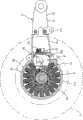
图3是表示从车体右侧观察后轮支撑用摆动臂的状态的侧视图。Fig. 3 is a side view showing a rear wheel support swing arm viewed from the right side of the vehicle body.
图4是表示从车体右侧观察后轮支撑用摆动臂的状态的侧视图。Fig. 4 is a side view showing a rear wheel support swing arm viewed from the right side of the vehicle body.
图5是后轮支撑用摆动臂的后视图。Fig. 5 is a rear view of the swing arm for supporting the rear wheel.
图6是主要部分的横向剖视图。Fig. 6 is a transverse sectional view of main parts.
图7是表示开关元件的冷却结构的剖视图。Fig. 7 is a cross-sectional view showing a cooling structure for a switching element.
[符号说明][Symbol Description]
11…后轮、12…后轮支撑用摆动臂、21a…臂部、21b…后轮支撑部、23…齿轮箱、31…马达、32…行星齿轮式减速机构、33…控制装置、34…绕组、35…定子、36…主磁铁、37…转子、40…输出轴、62…霍尔元件、64…开关元件、65…散热板、66…凸片、S…马达容纳空间。11...Rear wheel, 12...Swing arm for supporting rear wheel, 21a...Arm part, 21b...Rear wheel support part, 23...Gear box, 31...Motor, 32...Planetary gear type reduction mechanism, 33...Control device, 34... Winding, 35...stator, 36...main magnet, 37...rotor, 40...output shaft, 62...Hall element, 64...switching element, 65...radiating plate, 66...lug, S...motor accommodation space.
[发明的实施形式][Example of the invention]
下面,参照图1至图7详细地说明采用本发明的电动式动力单元的电动两轮车的一个实施形式。Next, an embodiment of an electric two-wheeled vehicle using the electric power unit of the present invention will be described in detail with reference to FIGS. 1 to 7 .
图1是本发明的电动两轮车的侧视图,图2是后轮支撑用摆动臂的平面图,图3和图4是表示从车体右侧观察后轮支撑用摆动臂的侧视图,图3表示将齿轮箱从臂主体上卸下并露出马达的状态,图4表示将齿轮箱和制动片安装到臂主体上的状态。图5是后轮支撑用摆动臂的后视图,图6是主要部分的横向剖视图,图7是表示开关元件的冷却结构的剖视图。Fig. 1 is the side view of electric two-wheel vehicle of the present invention, and Fig. 2 is the plan view of rear wheel support with swing arm, Fig. 3 and Fig. 4 are the side views that show rear wheel support with rear wheel support swing arm from the vehicle body right side view, Fig. 3 shows the state where the gear box is removed from the arm body to expose the motor, and Fig. 4 shows the state where the gear box and brake pads are attached to the arm body. 5 is a rear view of a swing arm for supporting a rear wheel, FIG. 6 is a transverse sectional view of main parts, and FIG. 7 is a sectional view showing a cooling structure of a switching element.
在这些图中,符号1所示根据该实施形式的电动两轮车。该电动两轮车1采用折叠式的车架2构成。车架2由具有叉头管3的前架4和通过支轴5连接到该前架4上的后架6构成。在前述叉头管3上可自由操舵地支撑着支撑前轮7的前叉8和操纵手柄9。In these figures,
前述后架6,在将车座10设置在上部的同时,在下端部上设置支撑后轮11的后轮支撑用摆动臂12,在前述车座10和前述摆动臂12之间装载电池13。前述车座10沿上下方向可自由摆动地支撑在后架6上,打开或关闭其下方的电池用容纳空间的上端开口(电池出入口)。电池13可在向上摆动前述车座10的状态下相对于后架6进行装卸。The
如图2所示,前述后轮支撑用摆动臂12由后轮11左侧向车体前后方向延伸的臂主体21、安装在臂主体21前端部的车体右侧上的前臂22、安装在前臂主体21后端部上的齿轮箱23、设置在臂主体21后端部和齿轮箱23内部的后轮驱动装置24构成,通过枢轴25(参照图1)将臂主体21和前臂22的前端部沿上下方向可自由摆动地支撑在前述后臂6上。As shown in Figure 2, the aforementioned rear wheel
如图1所示,前述臂主体21在向车体前后方向延伸的臂部21a的后端与侧面呈圆形的后轮支撑部21b形成一体。前述臂部21a的下面向下方突出设置有缓冲托板21c。在该缓冲托板21c和后臂6的下端托板6a之间夹装后缓冲单元26。As shown in FIG. 1 , the arm
如图6所示,前述后轮支撑部21b朝向车体右侧(在同一图的上侧)形成开放的有底圆筒状,将前述齿轮箱23用固定螺栓27(参照图4)固定到开口部上。As shown in FIG. 6, the aforementioned rear
前述后轮支撑用摆动臂12构成本发明的电动式动力单元,前述后轮支撑部21b和齿轮箱23构成本发明的电动式动力单元的壳体,由前述后轮支撑部21b和齿轮箱23围成的空间构成本发明的马达容纳空间S(参照图6)。在该马达容纳空间S中容纳后面所述的后轮驱动装置24。The aforementioned rear wheel
如图6所示,前述后轮驱动装置24由马达31、以与该马达31位于同一轴线上的方式设置的行星齿轮式减速机构32、以及控制前述马达31的控制装置33构成。As shown in FIG. 6 , the rear
前述马达31在该实施形式中采用轴向间隙式且轴线方向与车宽方向平行的结构。要详细描述的话,该马达31将具有多个绕组34的定子35配置在前述马达容纳空间S内的车体左侧的端部上并固定在臂主体21上,同时,具有与前述绕组34对向的主磁铁36的圆板状转子37配置在比定子35更靠车体右侧的位置上。这样,通过采用轴向间隙型马达31,绕组34位于同一平面上,后轮驱动装置24可以沿轴线方向紧凑地构成。另外,马达31并不限于轴向间隙型,也可以使用普通的径向型。In this embodiment, the
转子37的旋转轴38,通过轴承39将车体左侧端部可自由旋转地支撑在臂主体21上,其车体右侧的端部通过轴承41可自由旋转地支撑在后面所述的行星齿轮减速机构32输出轴40上。The rotating
如图3所示,前述绕组34沿马达31的旋转方向并列设置。这些绕组34沿着臂主体21的前述后轮支撑部21b的内周面以朝向图3中所示的侧视图中的车体前方开放的C字形并列设置。前述C字形开放部分,是通过将沿着圆周方向均匀地配置在后轮支撑部21b内周面整个区域中的多个绕组34中的3个去掉而形成的,后面所述的控制装置33的车体后侧的一半与该开放部分面对。As shown in FIG. 3 , the
如图6所示,前述转子37的外周部37a上固定主磁铁36,其内周部37b比前述外周部37a更偏向车体左侧且在其上固定旋转轴38。行星齿轮式减速机构32的车体左侧的端部与形成于前述外周部37a和内周部37b之间的筒状壁37c的内侧面对。As shown in FIG. 6 , the main magnet 36 is fixed to the outer peripheral portion 37 a of the rotor 37 , and the
行星齿轮式减速机构32由形成于前述马达31的旋转轴38上的太阳轮42、与该太阳轮42啮合的三个行星齿轮43、围绕这些行星齿轮43形成圆筒状且与各行星齿轮43啮合的内齿轮44、通过各个销45可自由旋转地支撑所有行星齿轮43的支座46构成。前述内齿轮44固定在前述齿轮箱23上,前述支座46,在具有前述销45的行星齿轮支撑部46a的车体右侧的端部与输出轴40形成一体,并通过轴承47可自由旋转地支撑在前述齿轮箱23上。后轮11连接到前述输出轴40上,马达31的动力被行星齿轮减速机构32减速并传递给后轮11。即,行星齿轮减速机构32的输出轴40构成后轮11的车轴。The planetary gear reduction mechanism 32 is composed of a sun gear 42 formed on the
如图2和图5所示,后轮11由将轮胎51安装在外周部上的盘轮52、通过安装螺栓53安装在该盘轮52轴心部上的制动鼓54构成。制动鼓54轴心部的凸台54a通过花键嵌合到前述输出轴40上,被锁定螺母55连接起来。具有前述制动鼓54的鼓式制动器在现有技术中是已知的,如图4所示,在支撑销56和凸轮57上通过拉伸弹簧58安装有一对制动片59、59。As shown in FIGS. 2 and 5 , the
前述盘轮52,安装有制动鼓54的内周部比具有轮缘52a的外周部更偏向车体右侧,在内周部和外周部之间容纳有马达装载部。在该实施形式中,如图5所示,盘轮52的内周部偏向车体右侧,使得从后面看后轮支撑用摆动臂12的马达装载部(后轮支撑部21和齿轮箱23)的车宽方向的中央部和后轮11重叠。在图5中,该电动两轮车1的车宽度方向的中心线由单点划线C表示。In the
如图3、4和6所示,前述控制装置33沿着臂部21a配置在臂主体21的后轮支撑部21b与前述臂部21a的边界部分,与上述马达31的绕组34彼此之间相面对且同时将马达31容纳在马达容纳空间S内。As shown in Figures 3, 4 and 6, the
并且,该控制装置33,如图6所示,转子位置检测用霍尔元件62安装在第一基板61上,开关元件64安装在第二基板63上。如图3所示,前述霍尔元件62采用的结构是,其检测部在与控制装置33中的转子37对向的车体右侧的侧面33a上露出,对转子37的主磁体36进行检测。Further, in the
前述开关元件64由功率晶体管构成,如图6和图7所示,安装在散热器65上,通过该散热器65连接到臂主体21上。散热器65由固定螺栓63a固定到前述第二基板63上。在该实施形式中,在臂主体21上竖立设置板状凸片66,使散热器65的断面形成コ字形,以便与该凸偏66嵌合。该嵌合部可以使一个部件相对于另一个部件沿嵌合方向(在图6和图7中为上下方向和与纸面垂直的方向)滑动。通过采用该嵌合结构,通过散热器65的凹部65a(参照图7)和前述凸片66的接触面将开关元件64的热传递给臂主体21。前述凸片66构成方案7所记载的发明的凸部,散热器65构成散热板。The
连接控制装置33和马达31的配线,如图3所示,由于控制装置33靠近绕组34,所以采用电极板71,连接控制装置33和电池13或加速器操作器件(图中未示出)的配线,如图3、4所示采用绝缘线72、73。前述电极板71的一端软钎焊到控制装置33的第二基板63上并且另一端从控制装置33向车体后方突出,所述另一端(后端部)连接到马达31的供电端子(图中未示出)上。前述绝缘线72、73虽然在图中未示出,但是沿前述臂部21a的车体内侧的侧面向车体前侧配线。The wiring for connecting the
按照上述结构构成的电动两轮车1的电动式动力单元,马达31和行星齿轮式减速机构32配置在同一轴线上且被支撑在一个壳体(后轮支撑部21b和齿轮箱23)上,由于控制马达31的控制装置33靠近马达31地容纳在前述壳体内的马达容纳空间S中,所以可以在一个容纳空间中容纳马达31和控制装置33,降低用于形成容纳空间的壁的数目。According to the electric power unit of the electric two-
并且,由于马达31和行星齿轮式减速机构32位于同一轴线上,所以可以将马达31和行星齿轮式减速机构32集合在一个部位进行配置。从而,如该实施形式所示,通过将该电动式动力单元作为动力源,可以形成驱动系统小型化的电动两轮车1。特别地,由于该电动两轮车1以从后面看马达装载部的车辆宽度方向的中央部和后轮11重合的方式构成,所以可以将电动式动力单元的马达装载部容纳在形成于后轮11内侧的死区中以减小宽度,可以进一步紧凑化。而且,从后面看前述马达装载部的车宽方向的中央部可以被后轮11挡住,可使其更为美观。In addition, since the
进而,根据该实施形式的电动式动力单元,由于控制装置33靠近马达31,所以可缩短连接控制装置33和马达31的配线的长度。而且,连接控制装置33和马达31的配线也可以容纳在马达容纳空间S中。在该实施形式中,由于从控制装置33凸出的电极板71被连接到马达31上,所以与在途中连接延长用配线的情况相比,可以减少连接部分的数目,提高电连接部的可靠性。Furthermore, according to the electric power unit of this embodiment, since the
根据该实施形式的电动式动力单元,由于在马达31的定子35的绕组34彼此之间配置控制装置33,所以可在形成于绕组彼此之间的死区中配置控制装置33,可以进一步缩短控制装置33和马达31之间的配线长度。According to the electric power unit of this embodiment, since the
形成于前述绕组34彼此之间的控制装置容纳用空间,由于可以通过除去在周向上均匀配置的多个绕组34之中的三个绕组34而形成,所以在不增大马达31直径的情况下,在马达31内容纳与绕组34等同或比其大的控制装置33。The space for accommodating the control device formed between the
前述控制装置33,由于转子位置检测用霍尔元件62安装在第一基板61上,所以不需要专门用于安装霍尔元件62的基板。从而,可以减少零件数目和组装工序。In the
前述霍尔元件62,由于采用检测主磁铁36的结构,所以不需要专门由霍尔元件62进行检测的传感器用磁铁。结果,可以进一步降低零件数目和组装工序。Since the
控制装置33,由于开关元件64的散热器65与臂主体21(马达容纳用壳体)接触,所以开关元件64的热通过散热器65传递给前述臂主体21。因而,可以有效地冷却开关元件64。In the
前述开关元件64的散热器65和臂主体21的接触部,由于コ字形的散热器65嵌合到突出设置在臂主体21上的板状凸片66上,所以增大了散热器65和臂主体21的接触部分的面积,可以提高散热效率。并且,由于散热器65可以略微相对于凸片66移动,所以臂主体21的振动不会经散热器65传递给开关元件64,可以防止外力施加在开关元件64和第二基板63的接触部分。并且,尽管将散热器65和臂主体21连接在一起,也不会产生热应力。The
此外,前述控制装置33,由于沿臂部21a配置在臂主体21的后轮支撑部21b中的车体前侧的端部上,所以控制装置33和马达31可以配置在车宽方向上大致相同的位置上,可以进一步形成在车的宽度方向上更加紧凑的电动两轮车1。并且,由于控制装置33位于马达31和车架2之间,所以连接装载在车架2上的电池13或其它电子零件和控制装置33的配线(绝缘线72、73)可以沿着后轮支撑用摆动臂12设置。In addition, since the
在上述实施形式中,展示了将本发明的电动式动力单元作为电动两轮车1的动力源的例子,但是,本发明的电动式动力单元也可以用于电动四轮车或电动三轮车等其他电动车辆。在采用这种结构的情况下,马达31和减速机构32的轴线与车的宽度方向平行,减速机构32的输出轴40作为驱动轮的车轴。并且,在构成这种电动车辆的情况下,也可以采用在后面看马达装载部的车宽方向的中央部和驱动轮重叠的结构。In the above-mentioned embodiment, the example of using the electric power unit of the present invention as the power source of the electric two-
[发明的效果][Effect of the invention]
根据上述说明的本发明,由于可以减少形成容纳马达和控制装置的空间所需的壁的数目,同时,可以将马达和减速机构集合配置在一个部位,能提供紧凑的电动式动力单元。According to the present invention as described above, since the number of walls required to form a space for accommodating the motor and the control device can be reduced, and the motor and the reduction mechanism can be collectively arranged at one location, a compact electric power unit can be provided.
并且,由于可以缩短连接控制装置和马达的配线的长度,所以伴随前述壁的数目减少可以降低制造成本。进而,由于连接控制装置和马达的配线也可以被容纳在马达容纳空间中,所以该配线不会被外力损伤,代替配线,可以将从控制装置突出的电极板固定到马达上以连接控制装置和马达,从而减少连接部分的数目。可以获得电连接部的可靠性高的电动式动力单元。Also, since the length of the wiring connecting the control device and the motor can be shortened, the manufacturing cost can be reduced along with the reduction in the number of the aforementioned walls. Furthermore, since the wiring connecting the control unit and the motor can also be accommodated in the motor housing space, the wiring will not be damaged by external force, instead of the wiring, an electrode plate protruding from the control unit can be fixed to the motor to connect control devices and motors, thereby reducing the number of connected parts. An electric power unit with high reliability of the electrical connection part can be obtained.
根据方案2所记载的发明,由于可以将控制装置配置在形成于绕组彼此之间的死区中,所以,控制装置与马达被容纳在同一个容纳空间中,也可以制造出更为紧凑的电动式动力单元。并且,由于可以进一步缩短控制装置和马达之间的配线长度,在进一步降低成本的同时,通过控制装置与绕组直接连接可进一步提高电连接的可靠性。According to the invention described in
根据方案3所记载的发明,由于可以不增大马达直径而将与绕组相同或更大的控制装置容纳在马达内,所以可实现电动式动力单元的小型化,可以将大型的控制装置设置与马达内。According to the invention described in
根据方案4所记载的发明,由于不需要专门用于安装霍尔元件的基板,所以可以减少部件数目和组装工序,进一步降低成本。According to the invention described in Claim 4, since a substrate dedicated to mounting the Hall element is not required, the number of parts and assembly steps can be reduced, and the cost can be further reduced.
根据方案5所记载的发明,由于不需要专门由霍尔元件检测的传感器用磁铁,可以进一步降低部件数目和组装工序,并进一步降低成本。According to the invention described in
根据方案6所记载的发明,由于开关元件的热通过散热板传递给马达容纳用壳体,所以可以有效地冷却开关元件。According to the invention described in
根据方案7所记载的发明,由于可以增大散热板和壳体的接触部分的面积,所以可以降低前述两者之间的热阻,更为有效地冷却开关元件。并且,由于散热板相对于壳体可在嵌合方向上移动,所以壳体的振动不会传递给开关元件,不会产生热应力,可以提高可靠性。According to the invention described in
方案8所记载的电动车辆,利用方案1~方案7所记载的电动式动力单元直接驱动驱动轮行驶。因此,根据方案8所记载的发明,可以提供在小型化的同时降低成本的电动车辆。The electric vehicle described in
根据方案9所记载的发明,由于可以将电动式动力单元的马达装载部容纳在形成于驱动轮内侧的死区中,所以可以实现将驱动轮连接到电动式动力单元的状态下的小型化。According to the invention described in
并且,由于从后面看前述马达装载部的车宽方向的中央部被驱动轮挡住,所以可以获得提高美观性的效果。In addition, since the central portion of the motor mounting portion in the vehicle width direction is blocked by the drive wheels when viewed from the rear, an effect of improving appearance can be obtained.
方案10所记载发明的电动两轮车,利用方案1~方案7所记载的电动式动力单元直接驱动驱动轮行驶。因此,根据方案10所记载的发明,可以提供在小型化的同时可降低成本的电动两轮车。The electric two-wheeled vehicle of the invention described in
根据方案11所记载的发明,由于可以将电动式动力单元的马达装载部容纳在形成于后轮内侧的死区中,所以可以实现将后轮连接到电动式动力单元上的状态下的小型化,可以提供车宽方向上小型化的电动两轮车。并且,由于马达装载部的重心靠近车宽方向的中心,所以车体左右方向的平衡非常容易。According to the invention described in
进而,由于从后面看前述马达装载部的车宽方向的中央部可以被后轮挡住,所以可获得提高美观性的效果。Furthermore, since the center portion of the motor mounting portion in the vehicle width direction can be blocked by the rear wheels when viewed from the rear, an effect of improving appearance can be obtained.
根据方案12所记载的发明,由于控制装置和马达配置在车宽方向上大致相同的位置上,所以可以提供在车宽方向上更加紧凑的电动两轮车。并且,由于控制装置位于马达和车架之间,连接装载在车架上的电池或其它电子部件和控制装置的配线可以沿后轮支撑用摆动臂设置,所以可以更容易地进行配线。According to the invention described in
Claims (10)
Applications Claiming Priority (3)
| Application Number | Priority Date | Filing Date | Title |
|---|---|---|---|
| JP194251/2001 | 2001-06-27 | ||
| JP2001194251AJP2003002277A (en) | 2001-06-27 | 2001-06-27 | Electric power unit, motor vehicle and power-assisted two wheeler |
| JP194251/01 | 2001-06-27 |
Publications (2)
| Publication Number | Publication Date |
|---|---|
| CN1394767A CN1394767A (en) | 2003-02-05 |
| CN100537288Ctrue CN100537288C (en) | 2009-09-09 |
Family
ID=19032419
Family Applications (1)
| Application Number | Title | Priority Date | Filing Date |
|---|---|---|---|
| CNB021282404AExpired - Fee RelatedCN100537288C (en) | 2001-06-27 | 2002-06-27 | Electric power units, electric vehicles and electric two-wheelers |
Country Status (6)
| Country | Link |
|---|---|
| US (1) | US7017694B2 (en) |
| EP (1) | EP1270395B1 (en) |
| JP (1) | JP2003002277A (en) |
| CN (1) | CN100537288C (en) |
| DE (1) | DE60213330T2 (en) |
| TW (1) | TW550208B (en) |
Families Citing this family (60)
| Publication number | Priority date | Publication date | Assignee | Title |
|---|---|---|---|---|
| JP2003002277A (en) | 2001-06-27 | 2003-01-08 | Yamaha Motor Co Ltd | Electric power unit, motor vehicle and power-assisted two wheeler |
| JP4188641B2 (en)* | 2002-08-13 | 2008-11-26 | ヤマハ発動機株式会社 | Motorcycle and rear arm of motorcycle |
| JP2004122981A (en)* | 2002-10-03 | 2004-04-22 | Yamaha Motor Co Ltd | Electric vehicle |
| CN2605187Y (en)* | 2003-02-13 | 2004-03-03 | 苏州工业园区诺亚科技有限公司 | Portable electric cycle |
| GB2400084A (en)* | 2003-03-31 | 2004-10-06 | Karbon Kinetics Ltd | Bicycle hub assembly |
| US7249644B2 (en)* | 2003-05-30 | 2007-07-31 | Honda Motor Co., Ltd. | Electric vehicle |
| EP1653595A4 (en) | 2003-07-18 | 2012-06-27 | Yamaha Motor Co Ltd | Motor generator and electric vehicle having the same |
| DE10351308A1 (en)* | 2003-10-31 | 2005-06-23 | Deere & Company, Moline | Vehicle axle system, torque tube, vehicle axle and vehicle |
| JP2005143169A (en) | 2003-11-05 | 2005-06-02 | Yamaha Motor Co Ltd | Electric vehicle |
| TWI283103B (en) | 2004-02-06 | 2007-06-21 | Yamaha Motor Co Ltd | Rotating electric machine and electrically driven vehicle |
| JP2006044633A (en)* | 2004-03-19 | 2006-02-16 | Yamaha Motor Co Ltd | Riding type vehicle |
| JP2006056354A (en)* | 2004-08-19 | 2006-03-02 | Honda Motor Co Ltd | High voltage wiring protection structure for electric vehicles |
| JP4684598B2 (en)* | 2004-08-20 | 2011-05-18 | 本田技研工業株式会社 | Suspension device in fuel cell vehicle |
| US7870917B2 (en)* | 2004-10-25 | 2011-01-18 | Sanyo Electric Co., Ltd. | Drive device for electrically movable vehicles and electric wheelchair having same |
| JP2006191782A (en) | 2004-12-09 | 2006-07-20 | Yamaha Motor Co Ltd | Rotating-electric machine |
| US7540995B2 (en)* | 2005-03-03 | 2009-06-02 | Icon Medical Corp. | Process for forming an improved metal alloy stent |
| JP4667090B2 (en)* | 2005-03-16 | 2011-04-06 | ヤマハ発動機株式会社 | Hybrid vehicle drive unit, hybrid vehicle and motorcycle |
| JP4317536B2 (en) | 2005-06-23 | 2009-08-19 | ヤマハ発動機株式会社 | Hybrid motorcycle drive device and hybrid motorcycle equipped with the same |
| JP2007015641A (en)* | 2005-07-11 | 2007-01-25 | Yamaha Motor Co Ltd | Power-assisted bicycle |
| US7686145B2 (en)* | 2005-09-21 | 2010-03-30 | Sanyo Electric Co., Ltd. | Drive device for electrically movable vehicles and electric wheelchair having same |
| JP5024811B2 (en) | 2006-03-17 | 2012-09-12 | 国立大学法人静岡大学 | Electric vehicle power supply device |
| JP4674722B2 (en)* | 2006-03-17 | 2011-04-20 | 国立大学法人静岡大学 | Electric vehicle power supply device |
| GB0613570D0 (en)* | 2006-07-07 | 2006-08-16 | Imp Innovations Ltd | An electrical machine |
| JP5122124B2 (en)* | 2006-07-26 | 2013-01-16 | 日立金属株式会社 | Axial gap type rotating machine, air-conditioning compressor, fan, and automobile equipped with the same |
| WO2009044418A1 (en)* | 2007-10-05 | 2009-04-09 | Oxygen, S.P.A. | Drive train for electric scooters |
| US20090255747A1 (en)* | 2008-04-10 | 2009-10-15 | Ridevehicles Llc | 3-Wheeled stand-up personal mobility vehicle and components therein |
| US20100212978A1 (en)* | 2009-02-23 | 2010-08-26 | Wen-Hung Huang | Bicycle with two operation molds |
| ES2428724T3 (en)* | 2009-03-27 | 2013-11-11 | Honda Motor Co., Ltd. | Electric vehicle astride |
| US8413748B2 (en)* | 2009-03-27 | 2013-04-09 | Honda Motor Co., Ltd. | Motor-driven vehicle |
| JP2011035954A (en)* | 2009-07-29 | 2011-02-17 | Sanyo Electric Co Ltd | Motor drive and motor-driven vehicle for mounting the same |
| JP5523770B2 (en)* | 2009-08-31 | 2014-06-18 | 本田技研工業株式会社 | Electric vehicle |
| JP5208095B2 (en)* | 2009-11-30 | 2013-06-12 | 本田技研工業株式会社 | Electric motorcycle |
| US20110198144A1 (en)* | 2010-02-12 | 2011-08-18 | Industrial Technology Research Institute | Electric bicycle and motor thereof |
| US20110259658A1 (en)* | 2010-04-22 | 2011-10-27 | Lin Hsiang Huang | Power output device for wheeled vehicle |
| US8706331B2 (en)* | 2010-05-27 | 2014-04-22 | Boxx Corp. | Two wheeled vehicle with all wheel drive system |
| JP5149938B2 (en) | 2010-06-11 | 2013-02-20 | 株式会社シマノ | Bicycle hub with built-in motor |
| JP5453550B2 (en)* | 2010-11-22 | 2014-03-26 | ヤマハ発動機株式会社 | Saddle-type electric vehicle power unit and saddle-type electric vehicle |
| EP2660136B1 (en)* | 2010-12-27 | 2015-07-22 | Kawasaki Jukogyo Kabushiki Kaisha | Saddle-type electric vehicle |
| CN103261015B (en)* | 2010-12-27 | 2016-11-23 | 川崎重工业株式会社 | electrical motorbike |
| KR101333798B1 (en) | 2011-06-21 | 2013-11-29 | 주식회사 아모텍 | Motor drive apparatus for vehicle and water pump using the same |
| KR101959078B1 (en)* | 2012-08-17 | 2019-03-15 | 삼성전자 주식회사 | In-wheel actuator and in-wheel assembly comprising the same |
| US10170959B2 (en)* | 2013-03-13 | 2019-01-01 | Regal Beloit America, Inc. | Electrical machines and methods of assembling the same |
| JP6271196B2 (en)* | 2013-09-19 | 2018-01-31 | Ntn株式会社 | In-wheel motor drive device |
| US9073585B2 (en)* | 2013-12-06 | 2015-07-07 | Blair Douglas Jackson | Light weight electric vehicle |
| US20170008580A1 (en) | 2014-03-31 | 2017-01-12 | Paha Designs, Llc | Low gravity all-surface vehicle |
| US9457647B2 (en) | 2014-03-31 | 2016-10-04 | Paha Designs, Llc | Low gravity all-surface vehicle |
| US10179508B2 (en) | 2014-03-31 | 2019-01-15 | Paha Designs, Llc | Low gravity all-surface vehicle |
| AT516540B1 (en)* | 2014-12-03 | 2016-09-15 | Babeluk Michael | RETROFITTING AND RETROFITTING A TWO-WHEEL |
| US20160347170A1 (en)* | 2015-05-28 | 2016-12-01 | Caterpillar Inc. | Integrated Wheel and Planet Carrier |
| IT201600116483A1 (en) | 2016-11-17 | 2018-05-17 | Piaggio & C Spa | Telescopic front suspension with anti-sinking effect |
| US10543874B2 (en) | 2017-05-17 | 2020-01-28 | Paha Designs, Llc | Low gravity all-surface vehicle and stabilized mount system |
| US11305840B2 (en) | 2017-11-02 | 2022-04-19 | Piaggio & C. S.P.A. | Electric drive motorcycle |
| TWI656043B (en) | 2017-11-08 | 2019-04-11 | 財團法人工業技術研究院 | Electric wheel |
| JP6692381B2 (en)* | 2018-03-13 | 2020-05-13 | 本田技研工業株式会社 | Power unit structure of electric vehicle |
| FR3084300B1 (en)* | 2018-07-24 | 2021-05-21 | Univ Le Havre Normandie | MOTORIZED WHEEL |
| US12179861B1 (en) | 2018-11-30 | 2024-12-31 | Robert P Thomas | Electric portal wheel hub system |
| US11697340B1 (en)* | 2018-11-30 | 2023-07-11 | Robert P Thomas | Electric portal wheel hub system |
| US12370881B1 (en) | 2020-10-05 | 2025-07-29 | Azak Inc. | Wheel for use in a low gravity vehicle |
| WO2022202567A1 (en)* | 2021-03-24 | 2022-09-29 | 本田技研工業株式会社 | In-wheel motor and saddle-riding-type vehicle |
| US12296665B2 (en) | 2021-08-13 | 2025-05-13 | Azak Inc. | High efficiency electric motor |
Family Cites Families (41)
| Publication number | Priority date | Publication date | Assignee | Title |
|---|---|---|---|---|
| US3566165A (en)* | 1969-05-06 | 1971-02-23 | Gen Motors Corp | Electric vehicle drive motor |
| GB1563227A (en)* | 1975-07-24 | 1980-03-19 | Papst Motoren Kg | Electric motors |
| IT1061847B (en)* | 1976-06-25 | 1983-04-30 | Piaggio & C Spa | DRIVE WHEEL WITH INTERNAL COMBUSTION ENGINE HOUSED IN ITS INTERNAL S * AZIO |
| US4536668A (en)* | 1982-09-13 | 1985-08-20 | Boyer Robert E | Vehicle mountable electrical generating system |
| JPS63107448A (en)* | 1986-10-23 | 1988-05-12 | Calsonic Corp | Flat motor |
| JPS6447252A (en)* | 1987-08-17 | 1989-02-21 | Japan Servo | Brushless motor |
| JP2769323B2 (en)* | 1988-06-29 | 1998-06-25 | アイシン・エィ・ダブリュ株式会社 | Motor drive device with reduction gear and electric vehicle |
| JPH02218865A (en) | 1989-02-20 | 1990-08-31 | Mitsubishi Electric Corp | coaxial starter |
| JPH0237027A (en)* | 1989-05-29 | 1990-02-07 | Seiko Epson Corp | Electric car |
| DE4012062A1 (en)* | 1990-04-10 | 1991-10-17 | Schlueter Gerd | ELECTRIC DRIVE SYSTEM FOR A VEHICLE |
| ES2084186T3 (en)* | 1990-10-09 | 1996-05-01 | Stridsberg Licensing Ab | AN ELECTRIC POWER TRAIN FOR VEHICLES. |
| US5144183A (en)* | 1990-11-20 | 1992-09-01 | Kollmorgen Corporation | Flat motor of reduced length |
| JP3093782B2 (en) | 1990-11-20 | 2000-10-03 | アイシン・エイ・ダブリュ株式会社 | Wheel motor with reduction gear |
| JP2922633B2 (en)* | 1990-11-29 | 1999-07-26 | 三菱電機株式会社 | Disk unit |
| US5087229A (en)* | 1991-05-06 | 1992-02-11 | General Motors Corporation | Independently suspended steerable motor wheel apparatus |
| US5272938A (en)* | 1992-12-04 | 1993-12-28 | Hsu Chi Hsueh | Flat rim type motor drive mechanism for bicycles |
| JP3377258B2 (en) | 1993-07-23 | 2003-02-17 | ヤマハ発動機株式会社 | Vehicle with electric motor |
| US5570752A (en) | 1993-07-26 | 1996-11-05 | Yamaha Hatsudoki Kabushiki Kaisha | Transmission arrangement for electric power assisted bicycle |
| US5691584A (en) | 1993-09-09 | 1997-11-25 | Honda Giken Kogyo Kabushiki Kaisha | Wheel motor for vehicles |
| US6121711A (en)* | 1993-11-08 | 2000-09-19 | Mitsubishi Denki Kabushiki Kaisha | Rotary motor and production method thereof, and laminated core and production method thereof |
| JP2892957B2 (en)* | 1994-12-09 | 1999-05-17 | 本田技研工業株式会社 | Motor with reduction gear |
| US5755304A (en) | 1994-08-08 | 1998-05-26 | Yamaha Hatsudoki Kabushiki Kaisha | Electric motor operated wheel |
| US5581136A (en)* | 1994-12-20 | 1996-12-03 | Li; I-Ho | Auxiliary magnetic motor (AMM) |
| JPH08300955A (en)* | 1995-05-12 | 1996-11-19 | Honda Motor Co Ltd | Power unit for electric vehicle |
| JPH09132040A (en)* | 1995-11-10 | 1997-05-20 | Honda Motor Co Ltd | Wheel motor with reduction gear |
| JP3016507B2 (en)* | 1996-02-22 | 2000-03-06 | 本田技研工業株式会社 | Crawler truck |
| JP3617729B2 (en) | 1996-07-04 | 2005-02-09 | ヤマハ発動機株式会社 | Electric auxiliary vehicle |
| JPH1016857A (en) | 1996-07-05 | 1998-01-20 | Yamaha Motor Co Ltd | Motor-assisted vehicle |
| US5818134A (en)* | 1997-04-22 | 1998-10-06 | Yang; Ying-Yen | Motor for motorcycles |
| JP3943196B2 (en)* | 1997-07-15 | 2007-07-11 | 本田技研工業株式会社 | Electric power unit |
| US5960901A (en)* | 1997-09-04 | 1999-10-05 | Corbin Pacific, Inc. | Battery-powered vehicle |
| US6199652B1 (en)* | 1997-12-11 | 2001-03-13 | Vectrix Corporation | Vehicle drive wheel assembly |
| JP3939862B2 (en)* | 1998-08-18 | 2007-07-04 | ヤマハ発動機株式会社 | Motor drive unit for electric bicycle |
| US6046518A (en)* | 1999-01-21 | 2000-04-04 | Williams; Malcolm R. | Axial gap electrical machine |
| DE10003452A1 (en) | 2000-01-27 | 2001-08-09 | Sig Positec Bergerlahr Gmbh & | Electric motor with epicyclic gear |
| US6321863B1 (en)* | 2000-06-26 | 2001-11-27 | Mac Brushless Motor Company | Hub motor for a wheeled vehicle |
| US6590306B2 (en)* | 2001-02-26 | 2003-07-08 | Yamaha Hatsudoki Kabushiki Kaisha | Electric motor driven wheel |
| JP2003002277A (en) | 2001-06-27 | 2003-01-08 | Yamaha Motor Co Ltd | Electric power unit, motor vehicle and power-assisted two wheeler |
| JP3984139B2 (en)* | 2001-10-19 | 2007-10-03 | ヤマハ発動機株式会社 | Power transmission device for electric motorcycles |
| US6765327B2 (en)* | 2002-03-27 | 2004-07-20 | The Timken Company | Integral driveline support and electric motor |
| US20030221887A1 (en)* | 2002-06-04 | 2003-12-04 | Chun-Pu Hsu | Electric wheel structure capable of being directly driven by power of motor |
- 2001
- 2001-06-27JPJP2001194251Apatent/JP2003002277A/enactivePending
- 2002
- 2002-06-12TWTW091112817Apatent/TW550208B/ennot_activeIP Right Cessation
- 2002-06-27USUS10/186,343patent/US7017694B2/ennot_activeExpired - Fee Related
- 2002-06-27EPEP02014362Apatent/EP1270395B1/ennot_activeExpired - Lifetime
- 2002-06-27DEDE60213330Tpatent/DE60213330T2/ennot_activeExpired - Lifetime
- 2002-06-27CNCNB021282404Apatent/CN100537288C/ennot_activeExpired - Fee Related
Also Published As
| Publication number | Publication date |
|---|---|
| EP1270395B1 (en) | 2006-07-26 |
| EP1270395A3 (en) | 2005-03-23 |
| TW550208B (en) | 2003-09-01 |
| DE60213330D1 (en) | 2006-09-07 |
| CN1394767A (en) | 2003-02-05 |
| EP1270395A2 (en) | 2003-01-02 |
| US7017694B2 (en) | 2006-03-28 |
| DE60213330T2 (en) | 2006-11-23 |
| JP2003002277A (en) | 2003-01-08 |
| US20030010551A1 (en) | 2003-01-16 |
Similar Documents
| Publication | Publication Date | Title |
|---|---|---|
| CN100537288C (en) | Electric power units, electric vehicles and electric two-wheelers | |
| JP6883012B2 (en) | Hub equipment and related systems | |
| JP6739520B2 (en) | Wheel module | |
| US6590306B2 (en) | Electric motor driven wheel | |
| US11577774B2 (en) | Electric drive device and electric power steering device | |
| CN100391756C (en) | Drive unit for driving a vehicle by an electric motor | |
| JP4348941B2 (en) | Mounting structure of rotating electrical machine for wheels | |
| JP2017519680A (en) | Stator assembly for electric motor wheels and stub axle support structure therefor | |
| CN101163605A (en) | Cooling structure for in-wheel motor | |
| ES2432060T3 (en) | Electric Drive Wheel Assembly | |
| US11407443B2 (en) | Electric drive device and electric power steering device | |
| JP2002252955A (en) | Inverter arrangement structure of wheel motor | |
| JP7083298B2 (en) | Motor structure and vehicle | |
| CN104139827A (en) | Wheel hub driving device and cooling element used for the wheel hub driving device | |
| US20190193775A1 (en) | Electromotive Drive Device and Electrically-Powered Steering Device | |
| JP2011035954A (en) | Motor drive and motor-driven vehicle for mounting the same | |
| US20200287440A1 (en) | Electric drive device and electric power steering device | |
| JP7156892B2 (en) | Motor structure | |
| JPH10285891A (en) | Wheel motor and vehicle equipped with it | |
| WO2012014969A1 (en) | Molded motor and mobile body mounted therewith | |
| CN216761432U (en) | Dual-drive motor, power system and electric automobile | |
| JPH0775994B2 (en) | Electric wheel of electric vehicle and three-wheel electric vehicle using the same | |
| CN114083970A (en) | Dual-drive motor, power system and electric automobile | |
| KR101284046B1 (en) | Inwheel motor with brake | |
| JP5931663B2 (en) | Electric caster |
Legal Events
| Date | Code | Title | Description |
|---|---|---|---|
| C06 | Publication | ||
| PB01 | Publication | ||
| C10 | Entry into substantive examination | ||
| SE01 | Entry into force of request for substantive examination | ||
| C14 | Grant of patent or utility model | ||
| GR01 | Patent grant | ||
| CF01 | Termination of patent right due to non-payment of annual fee | Granted publication date:20090909 Termination date:20170627 | |
| CF01 | Termination of patent right due to non-payment of annual fee |