CN100536792C - A navigation system and navigation method supporting multiple modes - Google Patents
A navigation system and navigation method supporting multiple modesDownload PDFInfo
- Publication number
- CN100536792C CN100536792CCNB2007100649002ACN200710064900ACN100536792CCN 100536792 CCN100536792 CCN 100536792CCN B2007100649002 ACNB2007100649002 ACN B2007100649002ACN 200710064900 ACN200710064900 ACN 200710064900ACN 100536792 CCN100536792 CCN 100536792C
- Authority
- CN
- China
- Prior art keywords
- coordinate system
- world
- track
- coordinate
- lesion
- Prior art date
- Legal status (The legal status is an assumption and is not a legal conclusion. Google has not performed a legal analysis and makes no representation as to the accuracy of the status listed.)
- Active
Links
- 238000000034methodMethods0.000titleclaimsabstractdescription47
- 238000003384imaging methodMethods0.000claimsabstractdescription146
- 230000003902lesionEffects0.000claimsabstractdescription143
- 239000000700radioactive tracerSubstances0.000claimsabstractdescription34
- 230000009466transformationEffects0.000claimsdescription49
- 239000013598vectorSubstances0.000claimsdescription22
- 239000011159matrix materialSubstances0.000claimsdescription12
- GFBKORZTTCHDGY-UWVJOHFNSA-NThiothixeneChemical compoundC12=CC(S(=O)(=O)N(C)C)=CC=C2SC2=CC=CC=C2\C1=C\CCN1CCN(C)CC1GFBKORZTTCHDGY-UWVJOHFNSA-N0.000claims1
- 238000001356surgical procedureMethods0.000description10
- 239000000243solutionSubstances0.000description7
- 238000010586diagramMethods0.000description6
- 239000003550markerSubstances0.000description4
- 238000009795derivationMethods0.000description3
- 230000000694effectsEffects0.000description3
- 238000002595magnetic resonance imagingMethods0.000description3
- FAPWRFPIFSIZLT-UHFFFAOYSA-MSodium chlorideChemical compound[Na+].[Cl-]FAPWRFPIFSIZLT-UHFFFAOYSA-M0.000description2
- 210000004556brainAnatomy0.000description2
- 238000002591computed tomographyMethods0.000description2
- 230000006378damageEffects0.000description2
- 239000000463materialSubstances0.000description2
- 238000005259measurementMethods0.000description2
- 210000000056organAnatomy0.000description2
- 230000001131transforming effectEffects0.000description2
- VVQNEPGJFQJSBK-UHFFFAOYSA-NMethyl methacrylateChemical compoundCOC(=O)C(C)=CVVQNEPGJFQJSBK-UHFFFAOYSA-N0.000description1
- 229920005372Plexiglas®Polymers0.000description1
- 208000027418Wounds and injuryDiseases0.000description1
- 239000012482calibration solutionSubstances0.000description1
- 238000006243chemical reactionMethods0.000description1
- 239000003026cod liver oilSubstances0.000description1
- 235000012716cod liver oilNutrition0.000description1
- 229910000365copper sulfateInorganic materials0.000description1
- ARUVKPQLZAKDPS-UHFFFAOYSA-Lcopper(II) sulfateChemical compound[Cu+2].[O-][S+2]([O-])([O-])[O-]ARUVKPQLZAKDPS-UHFFFAOYSA-L0.000description1
- 238000001514detection methodMethods0.000description1
- 238000002059diagnostic imagingMethods0.000description1
- 208000014674injuryDiseases0.000description1
- 230000010354integrationEffects0.000description1
- 239000004973liquid crystal related substanceSubstances0.000description1
- 238000002324minimally invasive surgeryMethods0.000description1
- 238000012544monitoring processMethods0.000description1
- 230000003287optical effectEffects0.000description1
- 238000000926separation methodMethods0.000description1
- 239000011780sodium chlorideSubstances0.000description1
- 238000003325tomographyMethods0.000description1
Images


Landscapes
- Measurement Of The Respiration, Hearing Ability, Form, And Blood Characteristics Of Living Organisms (AREA)
Abstract
Translated fromChinese
Description
Translated fromChinese技术领域technical field
本发明涉及一种手术导航系统及导航方法,特别是关于一种支持多种模式的导航系统及导航方法。The invention relates to an operation navigation system and a navigation method, in particular to a navigation system and a navigation method supporting multiple modes.
背景技术Background technique
手术导航系统是在医学影像设备(包括磁共振成像设备、计算机断层扫描设备(CT)、C型臂、X线设备、超声波成像系统等)所成图像的引导下,利用跟踪系统测量手术器械的位置,从而可以把病灶的三维图像和虚拟手术器械融合并显示在屏幕上,帮助医生精确定位病灶和手术器械的位置,并观察病灶周围的器官和组织,帮助医生避开重要的器官和组织,将手术器械安全地抵达预定地点,以便完成治疗。手术导航设备进入外科并用计算机改进或完善外科医师的能力以进行各项操作,如:监控定位和定向,制定治疗计划,提供最佳进入路径,在一定程度上降低了外科治疗所造成的损伤,缩短了手术时间。在某些传统的手术中,病灶不能直接用肉眼观察(例如不开刀的微创手术或者无创手术),或者不方便用肉眼观察(例如脑部神经外科手术),医生只能凭借肉眼观察病灶的图像,凭经验将手术器械放置到目标位置,这种方式造成的手术器件和病灶部位定位之间的误差,会拖延手术的时间,影响手术的质量,特别是这种误差有时会给患者带来不必要的痛苦和损伤。The surgical navigation system is guided by the image formed by medical imaging equipment (including magnetic resonance imaging equipment, computerized tomography equipment (CT), C-arm, X-ray equipment, ultrasonic imaging system, etc.), and uses a tracking system to measure the position of surgical instruments. position, so that the three-dimensional image of the lesion and the virtual surgical instrument can be fused and displayed on the screen, helping the doctor to accurately locate the position of the lesion and the surgical instrument, and observe the organs and tissues around the lesion, helping the doctor avoid important organs and tissues, Safely bring surgical instruments to their intended location so that treatment can be completed. Surgical navigation equipment enters the surgery and uses computers to improve or improve the ability of surgeons to perform various operations, such as: monitoring positioning and orientation, formulating treatment plans, providing the best access path, and reducing the damage caused by surgical treatment to a certain extent. The operation time is shortened. In some traditional operations, the lesion cannot be observed directly with the naked eye (such as minimally invasive surgery or non-invasive surgery without surgery), or it is inconvenient to observe with the naked eye (such as brain neurosurgery), and doctors can only observe the lesion with the naked eye. image, place the surgical instrument at the target position based on experience, the error between the surgical device and the location of the lesion caused by this method will delay the operation time and affect the quality of the operation, especially this error sometimes brings patients Unnecessary pain and injury.
发明内容Contents of the invention
针对上述问题,本发明的目的是提供一种支持多种模式的导航系统及导航方法,利用本发明可以将病灶图片和虚拟的手术器械放到同一个坐标系下观测,医生可以通过观测屏幕既能看到病灶,也能看到手术器械,进而准确而快速地将手术器械放置到目标位置,进行手术治疗。In view of the above problems, the object of the present invention is to provide a navigation system and navigation method that supports multiple modes. Using the present invention, the lesion pictures and virtual surgical instruments can be observed in the same coordinate system. The lesion can be seen, and the surgical instruments can also be seen, and then the surgical instruments can be accurately and quickly placed at the target position for surgical treatment.
本发明采取以下技术方案:一种支持多种模式的导航系统,其特征在于:它包括固定成像设备、跟踪系统、手术器械、病床、标定针、标定模和导航系统的软件程序;与所述固定成像设备位置对应设置有至少一套构成世界坐标系的示踪器,所述世界坐标系的位姿可以被所述跟踪系统测量;所述手术器械上设置有作为手术器械坐标系的手术器械示踪器,所述手术器械坐标系的位姿可被跟踪系统测量;所述病床上设置有构成病床坐标系的病床示踪器,所述病床坐标系可被所述跟踪系统测量;所述标定针由一根具有一定长度的针和示踪器共同构成,其经过标定后的针尖接触某点,即可测量此点的位置;所述标定模内部和表面分别设置了一组不对称分布的特征点集I和特征点集II,所述特征点集I的特征点可被所述固定成像设备成像,所述特征点集II的特征点可被所述跟踪系统测量;特征点集I和特征点集II的相对位置关系已知;经标定后,可通过各坐标系之间的相互变换关系,将所述病灶坐标和手术器械坐标变换到同一个坐标系中。The present invention adopts the following technical solutions: a navigation system supporting multiple modes, characterized in that it includes a fixed imaging device, a tracking system, surgical instruments, a hospital bed, a calibration needle, a calibration model and a software program of the navigation system; The position of the fixed imaging device is correspondingly provided with at least one set of tracers forming a world coordinate system, and the pose of the world coordinate system can be measured by the tracking system; the surgical instrument is provided with a surgical instrument as a surgical instrument coordinate system A tracer, the pose of the coordinate system of the surgical instrument can be measured by the tracking system; a bed tracer that constitutes the coordinate system of the hospital bed is set on the hospital bed, and the coordinate system of the hospital bed can be measured by the tracking system; The calibration needle is composed of a needle with a certain length and a tracer. After the needle tip touches a certain point after calibration, the position of this point can be measured; the inside and surface of the calibration mold are respectively provided with a set of asymmetric distribution. The feature point set I and the feature point set II of the feature point set I, the feature points of the feature point set I can be imaged by the fixed imaging device, the feature points of the feature point set II can be measured by the tracking system; the feature point set I The relative position relationship with the feature point set II is known; after calibration, the coordinates of the lesion and the coordinates of the surgical instrument can be transformed into the same coordinate system through the mutual transformation relationship between the coordinate systems.
在所述病床上患者的皮肤表面设置有与病灶位置对应的导航标志,所述导航标志可被所述固定成像设备成像,且可被所述跟踪系统测量。A navigation mark corresponding to the position of the lesion is set on the skin surface of the patient on the hospital bed, and the navigation mark can be imaged by the fixed imaging device and can be measured by the tracking system.
一种使用上述支持多种模式的导航系统的导航方法,其包括以下步骤:(1)在由固定成像设备、跟踪系统、手术器械和病床组成的系统中,固定成像设备自身具有固定成像设备坐标系,在位置不发生移动的地方安装示踪器构成世界坐标系,在所述手术器械上设置手术器械示踪器构成手术器械坐标系;(2)用固定成像设备测量标定模特征点集I的坐标,用跟踪系统测量特征点集II的坐标,通过这两组坐标数据标定出固定成像设备坐标系和世界坐标系之间的变换关系;(3)将载有患者的病床推入固定成像设备的成像区域,由固定成像设备提供病灶的图像数据和固定成像设备坐标系的位姿,由跟踪系统提供跟踪系统坐标系、手术器械坐标系的位姿,结合步骤2的标定结果建立各坐标系之间的变换关系;(4)利用坐标系的变换,将所述病灶与手术器械放到同一坐标系下观测;(5)根据病灶与手术器械相对位置的图像,移动手术器械,将其放置目标位置,进行手术治疗操作。A navigation method using the above-mentioned navigation system supporting multiple modes, which includes the following steps: (1) In the system composed of a fixed imaging device, a tracking system, a surgical instrument and a hospital bed, the fixed imaging device itself has a fixed imaging device coordinate system, the tracer is installed in the place where the position does not move to form the world coordinate system, and the surgical instrument tracer is set on the surgical instrument to form the surgical instrument coordinate system; (2) measure the calibration model feature point set I with a fixed imaging device The coordinates of the feature point set II are measured by the tracking system, and the transformation relationship between the fixed imaging equipment coordinate system and the world coordinate system is calibrated through these two sets of coordinate data; (3) Push the patient bed into the fixed imaging In the imaging area of the equipment, the image data of the lesion and the pose of the coordinate system of the fixed imaging device are provided by the fixed imaging device, and the pose and pose of the coordinate system of the tracking system and the coordinate system of the surgical instrument are provided by the tracking system, and the coordinates are established by combining the calibration results of step 2 (4) using the transformation of the coordinate system, put the lesion and the surgical instrument into the same coordinate system for observation; (5) move the surgical instrument according to the image of the relative position of the lesion and the surgical instrument, and place it Place the target location and perform surgical treatment operations.
另一种使用上述支持多种模式的导航系统的导航方法,其包括以下步骤:(1)在由固定成像设备、跟踪系统、手术器械和病床组成的系统中,固定成像设备自身具有固定成像设备坐标系,在位置不发生移动的地方安装示踪器构成世界坐标系,在所述手术器械上设置手术器械示踪器构成手术器械坐标系,在所述病床上或者与病灶相对位置不变处设置病床示踪器构成病床坐标系;(2)用固定成像设备测量标定模特征点集I的坐标,用跟踪系统测量特征点集II的坐标,通过这两组坐标数据标定出固定成像设备坐标系和世界坐标系之间的变换关系;(3)将载有患者的病床推入固定成像设备的成像区域,由固定成像设备提供病灶的图像数据,由跟踪系统提供病床坐标系的位姿信息;(4)将病床拖出固定成像设备的成像区域,移动至手术区域,由跟踪系统提供跟踪系统坐标系、病床坐标系和手术器械坐标系的位姿,由固定成像设备提供固定成像设备坐标系,结合步骤2的标定结果建立各坐标系之间的变换关系;(5)利用坐标系的变换,将所述病灶与手术器械放到同一坐标系下观测;(6)根据病灶与手术器械相对位置的图像,移动手术器械,将其放置目标位置,进行手术治疗操作。Another navigation method using the above-mentioned navigation system supporting multiple modes includes the following steps: (1) In the system composed of a fixed imaging device, a tracking system, a surgical instrument and a hospital bed, the fixed imaging device itself has a fixed imaging device Coordinate system, install the tracer at the place where the position does not move to form the world coordinate system, install the surgical instrument tracker on the surgical instrument to form the coordinate system of the surgical instrument, on the hospital bed or at the place where the relative position of the lesion remains unchanged Set the bed tracker to form the bed coordinate system; (2) Use the fixed imaging device to measure the coordinates of the calibration model feature point set I, and use the tracking system to measure the coordinates of the feature point set II, and calibrate the coordinates of the fixed imaging device through these two sets of coordinate data (3) Push the patient bed into the imaging area of the fixed imaging device, the fixed imaging device provides the image data of the lesion, and the tracking system provides the pose information of the bed coordinate system (4) Drag the hospital bed out of the imaging area of the fixed imaging device and move it to the operation area, the tracking system provides the poses of the tracking system coordinate system, the bed coordinate system and the surgical instrument coordinate system, and the fixed imaging device provides the coordinates of the fixed imaging device system, combined with the calibration results in step 2 to establish the transformation relationship between the coordinate systems; (5) using the transformation of the coordinate system, put the lesion and the surgical instrument into the same coordinate system for observation; (6) according to the focus and the surgical instrument The image of the relative position, move the surgical instrument, place it at the target position, and perform the surgical treatment operation.
上述各步骤(2)中用标定模对各坐标系标定时,采用了旋转量和平移量分开标定的方法,其步骤如下:(a)利用固定成像设备1测量特征点集I各点在固定成像设备坐标系里的坐标


再一种使用上述支持多种模式的导航系统的导航方法,其包括以下步骤:(1)在病床上的患者体表设置至少三个与病灶之间无相对移动的导航标志,在所述手术器械上设置手术器械示踪器构成手术器械坐标系;(2)将载有患者的病床推入固定成像设备的成像区域,由固定成像设备提供病灶的图像数据和导航标志的图像数据;(3)将病床拖出固定成像设备的成像区域,移动至手术区域,首先用软件在病灶图像上提取导航标志在固定成像设备坐标系里的坐标,再用跟踪系统测量导航标志在跟踪系统坐标系里的坐标,根据这两组数据得到固定成像设备坐标系和跟踪系统坐标系之间的变换关系;(4)由跟踪系统提供跟踪系统坐标系、手术器械坐标系的位姿,由固定成像设备提供固定成像设备坐标系的位姿,结合步骤3的标定结果建立各坐标系之间的变换关系;(5)利用坐标系的变换,将所述病灶与手术器械放到同一坐标系下观测;(6)根据病灶与手术器械相对位置的图像,移动手术器械,将其放置目标位置,进行手术治疗操作。Yet another navigation method using the above-mentioned navigation system that supports multiple modes, it includes the following steps: (1) setting at least three navigation marks that do not move relative to the lesion on the patient's body surface on the hospital bed, during the operation A surgical instrument tracer is set on the instrument to form a surgical instrument coordinate system; (2) The patient bed is pushed into the imaging area of the fixed imaging device, and the fixed imaging device provides the image data of the lesion and the image data of the navigation mark; (3) ) Drag the hospital bed out of the imaging area of the fixed imaging equipment and move it to the operation area. First, use the software to extract the coordinates of the navigation markers in the coordinate system of the fixed imaging equipment on the lesion image, and then use the tracking system to measure the coordinates of the navigation markers in the tracking system coordinate system coordinates, according to these two sets of data, the transformation relationship between the fixed imaging equipment coordinate system and the tracking system coordinate system is obtained; (4) The tracking system coordinate system and the pose of the surgical instrument coordinate system are provided by the tracking system, and the fixed imaging equipment provides Fixing the pose of the coordinate system of the imaging device, and establishing the transformation relationship between the coordinate systems in combination with the calibration results in step 3; (5) using the transformation of the coordinate system, placing the lesion and the surgical instrument under the same coordinate system for observation; ( 6) According to the image of the relative position of the lesion and the surgical instrument, move the surgical instrument, place it at the target position, and perform surgical treatment.
上述各步骤(2)中用标定模对各坐标系标定时,在所述导航系统的软件程序中设置有通过对特征点集I中特征点成像结果进行球心定位的程序,其包括以下步骤:(1)首先假设截面图上圆的面积S与截面在扫描方向上的坐标值之间满足正态分布;(2)沿球在同一轴向任意扫描三幅不同位置的截面圆图像,或扫描得到两幅不同位置的截面圆图像后,拟合出第三幅截面圆图像,由该截面圆面积与该截面圆在扫描方向的坐标值组成一组值;(3)将获得的三组值,拟合出一条高斯曲线,曲线上面积最大点对应的坐标值即为球心在该扫描方向上的坐标值;(4)按照同样的方法,得到球心在另外两个坐标轴方向的坐标值,将每一个轴向坐标值,组合在一起即为球心坐标。When each coordinate system is demarcated with a calibration module in the above-mentioned steps (2), the software program of the navigation system is provided with a program for locating the center of the sphere to the feature point imaging result in the feature point set 1, which includes the following steps : (1) First assume that the area S of the circle on the cross-sectional view satisfies a normal distribution with the coordinates of the cross-section in the scanning direction; (2) randomly scan three cross-sectional circle images at different positions along the same axis along the ball, or After scanning to obtain two cross-sectional circle images at different positions, fit the third cross-sectional circle image, and form a set of values by the area of the cross-sectional circle and the coordinate values of the cross-sectional circle in the scanning direction; (3) the three sets of obtained value, a Gaussian curve is fitted, and the coordinate value corresponding to the point with the largest area on the curve is the coordinate value of the center of the sphere in the scanning direction; Coordinate value, the combination of each axial coordinate value is the coordinate of the center of the sphere.
本发明由于采取以上技术方案,其具有以下优点:1本发明由于设置了各种示踪器、标定针和标定模,因此可以对各示踪器形成的坐标系用标定模进行标定,进而使各坐标系之间可以相互进行变换,实现将病灶图像和手术器械变换到同一坐标系中,使医生可以通过图像看到真实的手术器械与病灶的相对位置,而在图像的引导下进行精确的手术操作。2、本发明针对标定模上的特征点在固定成像设备成像过程中出现的球心位置不确定的问题,提出了一种球心定位方法,并将其预设在导航系统的软件中,因此可以在进行标定模标定时,从图像中得到精确的球心位置,使本发明导航系统导航效果更加精确。3、由于本发明对手术器械、病床等分别设置了示踪器,因此在通过标定模进行标定后,无论是在固定成像设备成像的同时,还是移动或变化手术器械,甚至移动病床到其它位置,都可以在本发明导航系统的控制下,进行多种模式的手术导航,并保证导航精度。4、本发明由于采取将平移量和旋转量分开标定的方式,有效地提高了标定精度。5、本发明标定模的特征点分布在立体空间里,相对于平面标定模(即特征点位于一个平面上),操作十分方便,可以一次性地提供一组分布于立体空间里的点,克服了使用平面标定模标定,需要手工平移标定模的缺点,使标定结果在固定成像设备的成像区域内准确可靠,特别是标定模的每个面的特征点的几何分布不一样,在计算时可自动匹配标定模特征点。本发明可以广泛用于各种手术导航过程中。Because the present invention adopts the above technical scheme, it has the following advantages: 1. The present invention can demarcate the coordinate system formed by each tracer with the calibration mould, and then make Each coordinate system can be transformed with each other, and the image of the lesion and the surgical instrument can be transformed into the same coordinate system, so that the doctor can see the relative position of the real surgical instrument and the lesion through the image, and carry out precise positioning under the guidance of the image. Surgical operation. 2. The present invention proposes a method for locating the center of the sphere, and presets it in the software of the navigation system, aiming at the problem that the position of the center of the sphere is uncertain during the imaging process of the fixed imaging equipment for the feature points on the calibration model. When the calibration mode is being calibrated, the precise position of the center of the sphere can be obtained from the image, so that the navigation effect of the navigation system of the present invention is more accurate. 3. Since the present invention is equipped with tracers for surgical instruments and hospital beds, etc., after calibration through the calibration model, whether it is imaging with a fixed imaging device, or moving or changing surgical instruments, or even moving the hospital bed to other positions , under the control of the navigation system of the present invention, various modes of surgical navigation can be performed, and the navigation accuracy can be guaranteed. 4. The present invention effectively improves the calibration accuracy by adopting the method of separately calibrating the translation amount and the rotation amount. 5. The feature points of the calibration model of the present invention are distributed in the three-dimensional space. Compared with the plane calibration model (that is, the feature points are located on a plane), the operation is very convenient, and a group of points distributed in the three-dimensional space can be provided at one time to overcome In addition to using the plane calibration model for calibration, the shortcomings of manual translation of the calibration model are required to make the calibration results accurate and reliable in the imaging area of the fixed imaging device. In particular, the geometric distribution of the feature points on each surface of the calibration model is not the same. Automatically match calibration model feature points. The present invention can be widely used in various surgical navigation procedures.
附图说明Description of drawings
图1是本发明结构示意图Fig. 1 is a structural representation of the present invention
图2是本发明标定模结构示意图Fig. 2 is a schematic diagram of the structure of the calibration model of the present invention
图3是本发明标定模一个面的特征点设置示意图Fig. 3 is a schematic diagram of feature point setting on one surface of the calibration model of the present invention
图4是本发明标定模的特征点分布示意图Fig. 4 is a schematic diagram of the distribution of feature points of the calibration model of the present invention
图5是采用固定成像设备所成图像示意图Figure 5 is a schematic diagram of an image formed by a fixed imaging device
图6是图5三个截面位置的示意图Fig. 6 is a schematic diagram of three cross-sectional positions in Fig. 5
图7是本发明沿三维坐标中的z轴扫描拟合出的高斯曲线Fig. 7 is the Gaussian curve that the present invention scans and fits along the z-axis in three-dimensional coordinates
图8是本发明球心定位几何关系示意图Fig. 8 is a schematic diagram of the positioning geometric relationship of the center of the sphere in the present invention
具体实施方式Detailed ways
下面结合附图和实施例对本发明进行详细的描述。The present invention will be described in detail below in conjunction with the accompanying drawings and embodiments.
如图1所示,本发明支持多种模式的导航系统是在一般治疗手术过程中使用的各种设备的基础上,增加本发明特别设置的一些设备组成的导航系统,下面仅就与本发明导航系统相关的设备进行简要描述。As shown in Figure 1, the navigation system supporting multiple modes of the present invention is based on the various devices used in the general treatment operation process, adding some devices specially set by the present invention to form a navigation system, the following is only related to the present invention A brief description of the equipment related to the navigation system.
本发明导航系统包括固定成像设备1、跟踪系统2、世界坐标系示踪器3、手术器械4及手术器械示踪器5、病床6及病床示踪器7、标定针8、标定模9和导航系统软件程序等,本发明还可以包括设置在患者体表的导航标志10。The navigation system of the present invention includes a fixed imaging device 1, a tracking system 2, a world coordinate system tracer 3, a surgical instrument 4 and a surgical instrument tracer 5, a sick bed 6 and a sick bed tracer 7, a calibration needle 8, a
本发明固定成像设备1的“固定”指的是在成像和手术的过程中,其位置不发生移动,例如磁共振成像设备、计算机断层扫描设备(CT)、C型臂、X线设备、超声波成像系统等。固定成像设备1用于对患者的病灶、标定模9内的特征点、导航标志10等成像,固定成像设备坐标系是固定成像设备1自身的属性,可以通过标定模的标定建立它和其它坐标系之间的坐标变换关系。The "fixation" of the fixed imaging device 1 of the present invention means that its position does not move during the imaging and operation process, such as magnetic resonance imaging equipment, computer tomography equipment (CT), C-arm, X-ray equipment, ultrasonic imaging equipment, etc. imaging systems, etc. The fixed imaging device 1 is used to image the patient's lesions, the feature points in the
本发明的跟踪系统2由位置传感器、工作站及相关电路等组成,跟踪系统2能够在跟踪系统的视场(保持测量精度的空间区域)内探测目标点的坐标,也能够测量目标坐标系的位置和姿态(称为位姿)信息,跟踪系统2可以是光学跟踪系统、电磁跟踪系统和机器人等。跟踪系统2利用其上的位置传感器对世界坐标系示踪器3、手术器械示踪器5、病床示踪器7等进行探测,完成对世界坐标系、手术器械坐标系和病床坐标系的位姿跟踪测量。Tracking system 2 of the present invention is made up of position sensor, work station and relevant circuit etc., and tracking system 2 can detect the coordinate of target point in the field of view of tracking system (the space area that keeps measuring precision), also can measure the position of target coordinate system and posture (referred to as pose) information, the tracking system 2 can be an optical tracking system, an electromagnetic tracking system, a robot, and the like. The tracking system 2 uses the position sensor on it to detect the world coordinate system tracer 3, the surgical instrument tracker 5, the hospital bed tracker 7, etc., and completes the positioning of the world coordinate system, the surgical instrument coordinate system and the hospital bed coordinate system. Attitude tracking measurement.
本发明的世界坐标系示踪器3、手术器械示踪器5和病床示踪器7都可以采用现有技术中由若干个(3个或3个以上)最小的示踪单位(比如表面具有荧光材料的示踪球)组成示踪器,此示踪单元的位置能直接被跟踪系统2里的位置传感器观测,从而示踪器3、5、7可分别作为一个坐标系,提供所依附设备的位姿信息。世界坐标系的位置一般与固定成像设备1连接在一起,也可以设置在其它位置,世界坐标系的位置在治疗中不产生移动。世界坐标系可以由一套或者多套示踪器3构成,如果将多套示踪器3安放在不同位置,在导航过程中可根据需要改变位置传感器的位置,保证位置传感器总能探测到其中的1个示踪器,从而得到世界坐标系的位姿。The world coordinate system tracer 3 of the present invention, the surgical instrument tracer 5 and the hospital bed tracer 7 all can adopt in the prior art by several (3 or more than 3) minimum tracer units (such as the surface has tracer balls of fluorescent material) to form a tracer, the position of the tracer unit can be directly observed by the position sensor in the tracking system 2, so that the tracers 3, 5, and 7 can be used as a coordinate system to provide the attached equipment pose information. The position of the world coordinate system is generally connected with the fixed imaging device 1, and it can also be set at other positions. The position of the world coordinate system does not move during the treatment. The world coordinate system can be composed of one or more sets of trackers 3. If multiple sets of trackers 3 are placed in different positions, the position of the position sensor can be changed as needed during the navigation process to ensure that the position sensor can always detect it. A tracker of , so as to obtain the pose of the world coordinate system.
本发明的手术器械4包括导管、导丝等精密器械,手术中被引入人体,对体内病灶进行诊断和局部治疗,手术器械4上连接有作为手术器械坐标系的手术器械示踪器5,由于手术器械4与手术器械示踪器5的物理尺寸和相对位置是确定的,因此手术器械4的位姿信息可以被跟踪系统2测量。The surgical instrument 4 of the present invention includes precision instruments such as catheters and guide wires, which are introduced into the human body during the operation to diagnose and treat local lesions in the body. The surgical instrument 4 is connected with a surgical instrument tracer 5 as a surgical instrument coordinate system. The physical size and relative position of the surgical instrument 4 and the surgical instrument tracker 5 are determined, so the pose information of the surgical instrument 4 can be measured by the tracking system 2 .
本发明的病床6上放置患者,并可相对固定成像设备1从起始位置运动到成像区域或手术区域等。在病床6上固定作为病床坐标系的病床示踪器7后,病床6的位姿信息就可以被跟踪系统2测量。在某些应用中(例如脑部的神经外科手术),在病床6上的患者身体上固定有支架,此时也可将病床示踪器7固定在支架上。在病床6或者支架上放置示踪器7的目的都是在病灶发生移动的情况下准确跟踪病灶的位置。在病床6上放置示踪器7,当病灶和病床6无相对移动时,病床6的移动和病灶的移动是一样的;同样的,在支架上放置示踪器7,当病灶和支架无相对移动时,支架的移动和病灶的移动是一样的。在下面的叙述中,病床示踪器7也可理解为支架的示踪器,病床的位姿也可理解为支架的位姿,在数学符号上不作明显的区别。The patient is placed on the hospital bed 6 of the present invention, and can move relative to the fixed imaging device 1 from the initial position to the imaging area or operation area, etc. After the bed tracker 7 serving as the bed coordinate system is fixed on the bed 6 , the pose information of the bed 6 can be measured by the tracking system 2 . In certain applications (for example neurosurgery of the brain), a support is fixed to the patient's body on the bed 6, and the bed tracker 7 can also be fixed to the support at this time. The purpose of placing the tracer 7 on the hospital bed 6 or the bracket is to accurately track the position of the lesion when the lesion moves. Place the tracer 7 on the bed 6, when the focus and the bed 6 have no relative movement, the movement of the bed 6 is the same as that of the focus; When moving, the movement of the stent is the same as that of the lesion. In the following description, the bed tracker 7 can also be understood as the tracker of the frame, and the pose of the bed can also be understood as the pose of the frame, and there is no obvious difference in mathematical symbols.
本发明的标定针8是由一根具有一定长度的针和示踪器共同构成,由于针尖与示踪器的物理尺寸和相对位置是确定的,因此经过标定后,针尖的位置可以被跟踪系统2测量,从而利用标定针8的针尖接触某个点,就可以测量此点的位置。The calibration needle 8 of the present invention is composed of a needle with a certain length and a tracer. Since the physical size and relative position of the needle point and the tracer are determined, the position of the needle point can be tracked by the tracking system after calibration. 2 measurement, thereby utilizing the needle tip of the calibration pin 8 to touch a certain point, the position of this point can be measured.
本发明的导航标志10是设置在患者病灶附近皮肤上的标志,导航标志10既能在固定成像设备1中成像,也能被跟踪系统2测量,通过注册可以计算出这两个坐标系之间的坐标转换关系。导航标志10有两个用途,一是验证跟踪精度,二是注册病灶图像,将图像和病灶实体对齐。The navigation mark 10 of the present invention is a mark set on the skin near the patient's lesion. The navigation mark 10 can be imaged in the fixed imaging device 1 and can also be measured by the tracking system 2. The distance between the two coordinate systems can be calculated by registration. coordinate transformation relationship. The navigation mark 10 has two purposes, one is to verify the tracking accuracy, and the other is to register the lesion image and align the image with the lesion entity.
上述注册是指有两组点的坐标数据,这两组点描述的是同一个物体,但由于两组点所在的坐标系不同导致其坐标不一样,通过注册可以计算出这两个坐标系之间的坐标转换关系。也叫做“配准”或“对齐”。The above registration refers to the coordinate data of two sets of points. These two sets of points describe the same object, but the coordinates of the two sets of points are different due to the different coordinate systems. Through registration, the difference between the two coordinate systems can be calculated. The coordinate transformation relationship between them. Also called "registration" or "alignment".
本发明的标定模9可以采用各种结构,本质上都是提供两组特征点集I和II,点集I能在成像设备中成像,从而得到点集I中每一个点在固定成像设备坐标系里的坐标,点集II能被跟踪系统测量,从而得到点集II中每一点在跟踪系统坐标系里的坐标。特征点集I与特征点集II之间的相对位置关系是已知的(称为标定模的几何信息),即如果知道特征点集I各点的坐标,就能计算出特征点集II各点的坐标;如果知道特征点集II各点的坐标,也可以计算出特征点集I各点的坐标。
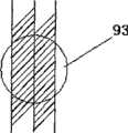
如图2、图3所示,本发明的标定模9包括由有机玻璃材料制成300mm×240mm×200mm的长方形标定模本体91,标定模本体91除底面外的其它五个面相似,每个面都具有一定厚度的特征层92,各面之间采用粘接或其它方式密封连接。在每一个特征层92内部都间隔设置有一组作为特征点93的球体(比如鱼肝油小球),五个面的所有特征点93共同组成了特征点集I。在每一特征层92的外表面与每个特征点93的位置对应,设置一个作为特征点94的凹坑,五个外表面上的特征点94共同组成了特征点集II。在标定模本体91内部,即六个面包起来的空间内是标定模溶液95,也可以没有标定模溶液。标定模溶液95可以采用氯化钠溶液、硫酸铜溶液等,其具有提高负载和信噪比的作用。特征点集I中的特征点93可以被固定成像设备1成像,并能够根据获得的图像计算出其中心;特征点集II的特征点94只要通过标定针8点击,就能够被跟踪系统2识别。As shown in Fig. 2 and Fig. 3,
上述实施例中,如果每个特征层92的特征点93、94是对称设置的,但是由于标定模本体1的两个背对背的面是对称的,不借助先验知识就不能知道某一点是处于这个面还是背对的那个面,那么在软件里注册时须人工通知软件特征点集I和II之间的点对应关系;如果在各面设置特征点93或特征点94时,选择不对称的空间分布(以特征点93为例,如图4所示),即有的位置是空置的,则软件可自动寻找对应关系。本发明为了在注册运算时实现自动匹配,因此在标定模本体91中设置的特征点集I和特征点集II的特征点93、94均采用不对称分布。这种不对称分布包括特征点集I中的各特征点93不对称分布,也包括特征点集II中的特征点94不对称分布,还包括特征点集I的特征点93与特征点集II中的特征点94之间不具有一一对应的关系。尽管这些特征点93、94不对称分布,但是一旦标定模制作完成,各特征点93、94之间的相互位置便是确定的,可以将各特征点93、94标号输入计算机,以方便随时取用。In the above-mentioned embodiment, if the feature points 93, 94 of each
上述各标定模9主要是用于标定和检验各坐标系之间的相互位置,由于特征点集I的特征点93能够从固定成像设备1所成的图像中分析得到,特征点集II的特征点94能够被跟踪系统2识别测量得到,并且特征点集I与特征点集II之间的关系已知(称为标定模的几何信息),只要知道其中特征点集I中特征点93(或者特征点集II中特征点94)的坐标,就能推算出特征点集II中特征点94(或特征点集I中特征点93)的坐标,通过它们之间的关系便可以建立固定成像设备坐标系和跟踪系统坐标系之间的变换关系。The above-mentioned
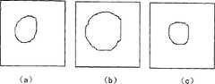
然而,根据各种成像设备(磁共振成像设备、计算机断层扫描设备(CT)、C型臂X线设备、超声波成像系统等)的成像特点可知,当固定成像设备1对标定模9中的特征点93进行扫描时(如图5所示),由于特征点93不是一个点,而是一个球体,扫描所得图像是积分得到的,并且所得到的图像并不规则,特别是距离设备扫描中心越远的位置,得到的图像变形越大(如图6中a、b、c所示),因此不能从图像中直接得到球体的球心。为此,在本发明导航系统的软件程序中需要添加一种基于高精度成像的球心定位程序,下面具体描述如下:However, according to the imaging characteristics of various imaging equipment (magnetic resonance imaging equipment, computed tomography equipment (CT), C-arm X-ray equipment, ultrasonic imaging system, etc.), it can be known that when the fixed imaging equipment 1 pairs with the features in the
如图7所示,为了得到特征点93真实的球心,本发明首先假设截面图上圆的面积S与截面在扫描方向上的坐标值之间满足正态分布;用固定成像设备1扫描特征点93,并沿同一轴向任意扫描三幅不同位置的截面圆图像,在扫描方向上的某一截面圆面积S和与该截面在扫描方向的坐标值可以组成一组值;由几何学可知,只要获得三组这样的值,就可以拟合出一条高斯曲线,曲线上面积最大点(峰值点)对应的坐标值就是球心在该扫描方向上的坐标值。曲线在z轴上的0点达到峰值,说明该点就是球心在z轴方向的坐标值。按照同样的方法,可以得到球心在另外两个坐标轴(x、y)方向的坐标值,将每一个轴向上利用三个截面计算出球心在这个轴向上的坐标值,组合在一起即可确定球心坐标。As shown in Figure 7, in order to obtain the real center of the sphere of the
在扫描过程中,有时可能会只得到两幅截面图,这时首先需要由这两幅图拟合出经过圆心的第三幅截面图,然后再用上述方法计算出球心的坐标位置。比如:During the scanning process, sometimes only two cross-sectional views may be obtained. At this time, it is first necessary to fit the third cross-sectional view through the center of the circle from these two pictures, and then use the above method to calculate the coordinate position of the center of the sphere. for example:
如图8所示,用一个平面去截一个球体(特征点93),会得到一个圆,图中(x,y,z)代表球心坐标,d代表球心到截面圆的距离,R0代表球半径,r代表截面圆半径,(a,b,c)代表截面圆圆心,t1代表截面圆法线方向。它们之间存在这样的几何关系:As shown in Figure 8, use a plane to cut a sphere (feature point 93), a circle will be obtained, in the figure (x, y, z) represents the coordinates of the center of the sphere, d represents the distance from the center of the sphere to the section circle, R0 Represents the radius of the ball, r represents the radius of the section circle, (a, b, c) represents the center of the section circle, and t1 represents the normal direction of the section circle. There is such a geometric relationship between them:
d2+r2=R02d2 +r2 =R02
已知球体的近似半径R0是3mm,通过分析图像,可以得到截面圆的圆心坐标(a,b,c)、圆的面积S,利用圆面积S可以得到截面圆半径r,利用球心和圆心坐标可以得到球心到截面圆的距离d,从而可以利用公式(1)得到该轴向上的球心坐标(x,y,z)。The approximate radius R0 of the known sphere is 3mm. By analyzing the image, the center coordinates (a, b, c) of the cross-section circle and the area S of the circle can be obtained. The radius r of the cross-section circle can be obtained by using the area S of the circle. Using the center of the sphere and The coordinates of the center of the circle can be used to obtain the distance d from the center of the sphere to the section circle, so that the coordinates (x, y, z) of the center of the sphere on the axis can be obtained by using the formula (1).
由几何关系,我们知道,只要知道了两个面的参数,就可以用几何的方法列出如下的联立方程,解出球心的坐标值来:From the geometric relationship, we know that as long as the parameters of the two surfaces are known, the following simultaneous equations can be listed geometrically to solve the coordinates of the center of the sphere:
对第一个面:For the first face:
这样可以解出两组值来,从几何上来讲是上下各一个。In this way, two sets of values can be solved, geometrically speaking, one for the upper and lower.
对第二个面:For the second face:
也可以解出两组值来,也是上下各一个。You can also solve two sets of values, one for the upper and lower.
上面解出的四个球心,应该有两个其实是同一点(当然肯定存在误差)。我们求一下每两点间的距离,l1,l2,l3,l4,则距离最小的两点应该就是正确的球心点,所以把这两点取平均,得到我们要的球心的初值。Of the four centers solved above, two of them should actually be the same point (of course there must be errors). Let's find the distance between each two points, l1 , l2 , l3 , l4 , then the two points with the smallest distance should be the correct center of the sphere, so take the average of these two points to get the center of the sphere we want initial value.
有了球心的初值,还知道球半径R0,也就得到了过球心的截面圆信息,综合已有的两个截面圆信息,就可以利用本发明方法计算球心。由于已经有了三个截面圆的信息(圆心,半径),可以计算出圆面积;由于圆心坐标值已知,也就得到了三组值,每组值由扫描方向上的某一截面圆面积和与该截面在扫描方向的坐标值组成,把这三组值作为高斯曲线上的点坐标,就可以拟合出一条高斯曲线,从而得到球心在该扫描方向上的坐标值。利用同样的方法,可以得到球心在另两个方向上的坐标值,从而得到球心位置坐标。With the initial value of the center of the sphere and the radius R0 of the sphere, the information of the cross-sectional circle passing through the center of the sphere is obtained, and the method of the present invention can be used to calculate the center of the sphere by combining the two existing information of the sectional circles. Since there are already three cross-sectional circle information (center, radius), the area of the circle can be calculated; since the coordinates of the center of the circle are known, three sets of values are obtained, and each set of values is determined by the area of a certain cross-sectional circle in the scanning direction and the coordinates of the cross section in the scanning direction, using these three sets of values as point coordinates on the Gaussian curve, a Gaussian curve can be fitted to obtain the coordinates of the center of the sphere in the scanning direction. Using the same method, the coordinate values of the center of the sphere in the other two directions can be obtained, thereby obtaining the position coordinates of the center of the sphere.
本发明导航系统的实质是将病灶图片和虚拟的手术器械放到同一个坐标系下观测,即同时显示在工作的屏幕上(可以是液晶屏幕、投影屏幕或者其它形式的显示器材),并且屏幕上两者的相对位置和真实的病灶和手术器械的相对位置相同,从而医生通过观测屏幕既能看到病灶,也能看到手术器械,进而准确而快速地将手术器械送到目标位置。The essence of the navigation system of the present invention is to put the lesion picture and the virtual surgical instrument into the same coordinate system for observation, that is, to display them on the working screen (which can be a liquid crystal screen, a projection screen or other forms of display equipment) at the same time, and the screen The relative position of the above two is the same as that of the real lesion and the surgical instrument, so that the doctor can see both the lesion and the surgical instrument through the observation screen, and then accurately and quickly send the surgical instrument to the target position.
采用本发明的导航系统,本发明可以完成以下两种工作模式(实时和非实时)的运行:Adopt the navigation system of the present invention, the present invention can finish the operation of following two kinds of working modes (real-time and non-real-time):
工作模式一:患者躺在病床6上,将病床6推入固定成像设备1的成像区域内,在扫描病灶的同时,实时地进行手术。其中,固定成像设备1提供病灶的图像数据,跟踪系统2提供手术器械4的位姿信息,利用坐标变换将病灶和手术器械4放到同一个坐标系下观测,同时显示在屏幕上,即医生在屏幕上看到的病灶和手术器械4的相对位置,就是实际的病灶和手术器械4的相对位置。Working mode 1: The patient lies on the sickbed 6, pushes the sickbed 6 into the imaging area of the fixed imaging device 1, and performs surgery in real time while scanning the lesion. Among them, the fixed imaging device 1 provides the image data of the lesion, and the tracking system 2 provides the pose information of the surgical instrument 4. Using coordinate transformation, the lesion and the surgical instrument 4 are observed in the same coordinate system and displayed on the screen at the same time, that is, the doctor The relative position of the lesion and the surgical instrument 4 seen on the screen is the actual relative position of the lesion and the surgical instrument 4 .
工作模式二:患者躺在病床6上,将病床6推入固定成像设备1的成像区域内,得到病灶的图像,然后将病床6拖出至一地点进行手术(患者和病床之间无相互移动),非实时地进行手术。其中,固定成像设备1提供病灶的图像数据,跟踪系统2提供手术器械3、病床6的位姿信息,利用坐标变换将病灶和手术器械4放到同一个坐标系下观测,同时显示在屏幕上,即医生在屏幕上看到的病灶和手术器械4的相对位置,就是实际的病灶和手术器械4的相对位置。Working mode 2: The patient lies on the sickbed 6, pushes the sickbed 6 into the imaging area of the fixed imaging device 1, obtains the image of the lesion, and then drags the sickbed 6 out to a place for surgery (there is no mutual movement between the patient and the sickbed ), the operation is performed in non-real time. Among them, the fixed imaging device 1 provides the image data of the lesion, and the tracking system 2 provides the pose information of the surgical instrument 3 and the hospital bed 6. The lesion and the surgical instrument 4 are observed in the same coordinate system by using coordinate transformation, and displayed on the screen at the same time , that is, the relative position of the lesion and the surgical instrument 4 seen by the doctor on the screen is the actual relative position of the lesion and the surgical instrument 4 .
为支持以上两种工作模式,本发明系统支持以下三种导航模式,在具体描述本发明导航模式之前,先对描述中出现的变量定义如下(如表1所示):In order to support the above two working modes, the system of the present invention supports the following three navigation modes. Before describing the navigation mode of the present invention in detail, the variables that appear in the description are defined as follows (as shown in Table 1):
表1:变量的定义Table 1: Definition of variables

导航模式A:为了进行第一种工作模式,本发明采用示踪器3作为世界坐标系(如图1所示),其是设置在固定成像设备1上的,因此其与固定成像设备1的相对位置保持不变,在手术器械4上固定手术器械示踪器5作为手术器械坐标系。通过标定模9标定,可以得到固定成像设备坐标系和世界坐标系之间的坐标变换关系,使病灶(固定成像设备1提供其图像和位姿信息)能变换到世界坐标系中(此标定工作只需在安装设备时做一次,只要示踪器3和固定成像设备1之间没有相对移动,以后的手术都可以直接采用其标定结果)。同时通过标定模9标定得到手术器械4在手术器械坐标系里的位姿(每次手术都要进行标定,因为一般在手术前才将手术器械示踪器5固定,且很可能在手术过程中进行手术器械4与手术器械示踪器5的分离、固定)。在手术过程中,跟踪系统2测量世界坐标系的位姿,得到跟踪系统2自己的坐标系和世界坐标系的转换关系;同时,跟踪系统2测量手术器械坐标系的位姿,得到手术器械坐标系和世界坐标系之间的转换关系,从而将手术器械4也变换到世界坐标系观测。除了统一将病灶和手术器械4变换到世界坐标系观测,也可以将它们变换到其它坐标系观测,例如固定成像设备坐标系或者跟踪系统坐标系等。Navigation Mode A: In order to carry out the first working mode, the present invention adopts the tracer 3 as the world coordinate system (as shown in FIG. 1 ), which is set on the fixed imaging device 1, so it is consistent with the fixed imaging device 1 The relative position remains unchanged, and the surgical instrument tracker 5 is fixed on the surgical instrument 4 as the surgical instrument coordinate system. Through the
导航模式A坐标变换关系具体的推导过程如下:The specific derivation process of the coordinate transformation relationship in navigation mode A is as follows:
在世界坐标系里观测病灶和手术器械4,固定成像设备1扫描病灶,得到其图像数据,其中包括病灶的任意一点在固定成像设备坐标系里的坐标根据事先标定好的固定成像设备坐标系和世界坐标系之间的变换关系
跟踪系统2测量手术器械示踪器5的位姿信息

手术器械4上任意一点T在手术器械坐标系里的坐标
至此,病灶和手术器械4已经被放到同一个坐标系(世界坐标系)中观测,它们可以被显示在屏幕上。医生在屏幕上看到的病灶和手术器械4的相对位置,就是实际的病灶和手术器械4的相对位置。So far, the lesion and the surgical instrument 4 have been observed in the same coordinate system (world coordinate system), and they can be displayed on the screen. The relative position of the lesion and the surgical instrument 4 seen by the doctor on the screen is the actual relative position of the lesion and the surgical instrument 4 .
除了世界坐标系,病灶和手术器械4也可以被变换到其它的坐标系中观测,例如固定成像设备坐标系或者跟踪系统坐标系。In addition to the world coordinate system, the lesion and the surgical instrument 4 can also be transformed into other coordinate systems for observation, such as a fixed imaging device coordinate system or a tracking system coordinate system.
使用固定成像设备坐标系观测,由于病灶已经处于固定成像设备坐标系,其任意一点的坐标为
使用跟踪系统坐标系观测,病灶的任意一点和手术器械4的任意一点在跟踪系统坐标系中的坐标分别为Using the tracking system coordinate system to observe, the coordinates of any point of the lesion and any point of the surgical instrument 4 in the tracking system coordinate system are respectively
导航模式B:为了进行第二种工作模式,可以在导航模式A的标定方法和跟踪方法的基础上扩展。同样地,使用示踪器3作为世界坐标系,它和固定成像设备1的相对位置保持不变,在手术器械4上固定手术器械示踪器5。此外,为了适应病床6(患者)的移动,还要在病床6上固定病床示踪器7。在手术过程中,病灶在固定成像设备1里成像后,随着病床6移动到进行手术的位置,利用固定成像设备坐标系和世界坐标系之间的坐标变换关系以及病床6的位姿信息,可以将病灶变换到世界坐标系中观测。手术器械4的跟踪方法和导航模式A中的方法一样。除了统一将病灶和手术器械4变换到世界坐标系观测,也可以将它们变换到其它坐标系,例如固定成像设备坐标系,跟踪系统坐标系或者病床坐标系等。Navigation mode B: In order to carry out the second working mode, it can be extended on the basis of the calibration method and tracking method of navigation mode A. Similarly, using the tracker 3 as the world coordinate system, its relative position with the fixed imaging device 1 remains unchanged, and the surgical instrument tracker 5 is fixed on the surgical instrument 4 . In addition, in order to adapt to the movement of the hospital bed 6 (patient), the bed tracker 7 is also fixed on the hospital bed 6 . During the operation, after the lesion is imaged in the fixed imaging device 1, as the hospital bed 6 moves to the position where the operation is performed, using the coordinate transformation relationship between the coordinate system of the fixed imaging device and the world coordinate system and the pose information of the hospital bed 6, The lesion can be transformed into the world coordinate system for observation. The tracking method of the surgical instrument 4 is the same as that in the navigation mode A. In addition to uniformly transforming the lesion and surgical instruments 4 into the world coordinate system for observation, they can also be transformed into other coordinate systems, such as the fixed imaging equipment coordinate system, the tracking system coordinate system or the hospital bed coordinate system.
导航模式B坐标变换关系具体的推导过程如下:The specific derivation process of the coordinate transformation relationship in navigation mode B is as follows:
在世界坐标系里观测病灶和手术器械4,患者被推入固定成像设备1成像时,病灶的任意一点在世界坐标系里的坐标即公式(1)描述的Observe the lesion and surgical instrument 4 in the world coordinate system, and when the patient is pushed into the fixed imaging device 1 for imaging, the coordinates of any point of the lesion in the world coordinate system are described by formula (1)
其中下标0表示病床6被推入固定成像设备1,此时病床坐标系位姿
由式(1)和(7)可知此时病灶的任意一点在病床坐标系中的坐标为From formulas (1) and (7), it can be known that the coordinates of any point of the lesion in the bed coordinate system at this time are
成像完毕后,病灶(患者)随着病床6运动到手术位置(用下标1表示)。由于病人和病床6无相对移动,病灶在病床6上的坐标保持不变After the imaging is completed, the lesion (patient) moves to the operation position (indicated by subscript 1) along with the hospital bed 6 . Since there is no relative movement between the patient and the bed 6, the coordinates of the lesion on the bed 6 remain unchanged
此时病床6的位姿
由式(8)~(10)可得出此时病灶在世界坐标系里的坐标为From formulas (8) to (10), it can be concluded that the coordinates of the lesion in the world coordinate system at this time are
手术器械4的任意一点在世界坐标系里的坐标和式(3)描述的一样The coordinates of any point of the surgical instrument 4 in the world coordinate system are the same as those described by formula (3)
至此,病灶和手术器械已经被放到同一个坐标系(世界坐标系)中观测。So far, the lesion and surgical instruments have been observed in the same coordinate system (world coordinate system).
除了世界坐标系,病灶和手术器械也可以被变换到其它的坐标系中观测,例如固定成像设备坐标系,跟踪系统坐标系或者病床坐标系。In addition to the world coordinate system, lesions and surgical instruments can also be transformed into other coordinate systems for observation, such as fixed imaging equipment coordinate system, tracking system coordinate system or hospital bed coordinate system.
使用固定成像设备坐标系观测,病灶的任意一点和手术器械4的任意一点在固定成像设备坐标系中的坐标分别为Using the fixed imaging equipment coordinate system to observe, the coordinates of any point of the lesion and any point of the surgical instrument 4 in the fixed imaging equipment coordinate system are respectively
使用跟踪系统坐标系观测,病灶的任意一点和手术器械4的任意一点在跟踪系统坐标系中的坐标分别为Using the tracking system coordinate system to observe, the coordinates of any point of the lesion and any point of the surgical instrument 4 in the tracking system coordinate system are respectively
使用病床坐标系观测,病灶的任意一点和手术器械4的任意一点在病床坐标系中的坐标分别为Using the sick bed coordinate system to observe, the coordinates of any point of the lesion and any point of the surgical instrument 4 in the sick bed coordinate system are respectively
导航模式C:为了进行第二种工作模式,可以采用与导航模式B不同的标定方法和跟踪方法。其是在患者体表固定能在固定成像设备1中成像的导航标志10(数量不少于3个),并在固定成像设备1中成像,手术过程中,导航标志10和病灶之间无相对移动。在病床6(患者)被拉出到达手术区域后,在病灶图像上提取导航标志10在固定成像设备坐标系里的坐标,并用跟踪系统2测量患者体表的导航标志10在跟踪系统坐标系里的坐标,将这两组数据注册,从而在某坐标系(例如跟踪系统坐标系)中将病灶图像和真正的病灶的位置重合在一起,由于此时手术器械4也被变换到此坐标系(例如跟踪系统坐标系),因此可以实现病灶和手术器械4的一起观测,然后就能开始手术。Navigation mode C: In order to carry out the second working mode, different calibration methods and tracking methods from navigation mode B can be used. It is fixed on the body surface of the patient with navigation markers 10 (the number is not less than 3) that can be imaged in the fixed imaging device 1 and imaged in the fixed imaging device 1. During the operation, there is no relative relationship between the navigation markers 10 and the lesion. move. After the hospital bed 6 (patient) is pulled out and arrives at the operating area, extract the coordinates of the navigation marker 10 in the coordinate system of the fixed imaging device on the lesion image, and use the tracking system 2 to measure the coordinates of the navigation marker 10 on the patient's body surface in the tracking system coordinate system The coordinates of these two sets of data are registered, so that the lesion image and the real lesion position are superposed together in a certain coordinate system (such as the tracking system coordinate system), because the surgical instrument 4 is also transformed to this coordinate system at this time ( For example, the tracking system coordinate system), so the observation of the lesion and the surgical instrument 4 can be realized together, and then the operation can be started.
导航模式C坐标变换关系具体的推导过程如下:The specific derivation process of the C coordinate transformation relationship in the navigation mode is as follows:
在病床6到位后,在病灶图像上将nnav个导航标志10(nnav≥3,一般nnav等于4),提取出来,得到导航标志10在固定成像设备坐标系里的三维坐标

其中为固定成像设备坐标系在跟踪系统坐标系里的位姿。通过式(15)可得到nnav个方程,并解出

手术器械4上的任意一点T在手术器械坐标系里的坐标
至此,病灶和手术器械4已经被放到同一个坐标系(跟踪系统坐标系)中观测,它们可以被显示在屏幕上,医生在屏幕上看到的病灶和手术器械4的相对位置,就是实际的病灶和手术器械4的相对位置。So far, the lesion and the surgical instrument 4 have been observed in the same coordinate system (tracking system coordinate system), and they can be displayed on the screen. The relative position of the lesion and the surgical instrument 4 seen by the doctor on the screen is the actual The relative position of the lesion and the surgical instrument 4 .
为了使医生不需要再次使用跟踪系统2测量导航标志点10,可增加一个示踪器作为世界坐标系,其位姿
用下标0表示初始的标定位置,1表示跟踪系统2的位置传感器移动到新位置。将病灶的任意一点由跟踪系统坐标系变换到世界坐标系The subscript 0 is used to indicate the initial calibration position, and 1 indicates that the position sensor of the tracking system 2 has moved to a new position. Transform any point of the lesion from the tracking system coordinate system to the world coordinate system
将手术器械4的任意一点变换到世界坐标系Transform any point of the surgical instrument 4 to the world coordinate system
这样我们就把病灶和手术器械4都放到世界坐标系里观测,当位置传感器移动后,世界坐标系在位置传感器的位姿
也可以在跟踪系统中观察病灶和手术器械Lesions and surgical instruments can also be observed in the tracking system
上述固定成像设备坐标系的标定中,固定成像设备1扫描一个物体得到图像,所用的空间坐标系为固定成像设备坐标系,为了将图像从固定成像设备坐标系变换到其它的坐标系(如世界坐标系),就需要进行标定工作,得到成像坐标系和某坐标系R(如世界坐标系或跟踪系统坐标系等)之间的变换关系
本发明采用标定模9和跟踪系统2来标定固定成像设备坐标系与世界坐标系之间的变换关系
根据上述标定模9结构的描述可知,固定成像设备扫描标定模9,得到特征点集I的每一特征点93在固定成像设备坐标系里的坐标

由这些方程解可解出固定成像设备坐标系与跟踪坐标系之间的变换关系
其中由跟踪系统2测量世界坐标系得到。in It is obtained by measuring the world coordinate system by tracking system 2.
为了提高导航模式A和导航模式B中的标定精度,本发明在用标定模9进行标定时,采用了旋转量和平移量分开标定的方法In order to improve the calibration accuracy in navigation mode A and navigation mode B, the present invention adopts a separate calibration method for the rotation amount and the translation amount when the

将点坐标point coordinates
V=(X 1)T=(x y z 1)TV = (X 1)T = (x y z 1)T
和式(23)代入(21)得到and formula (23) into (21) to get
一般的标定办法是利用固定成像设备1测量特征点集I各点在固定成像设备坐标系里的坐标


这样做可以在特征点集I、II附近的区域得到好的局部标定结果,但是由于视场比较大,而标定模的特征点93只是视场里点的一小部分,因此在固定成像设备1的整个视场内标定的精度受旋转矩阵
首先,利用固定成像设备1测量特征点集I各特征点93在固定成像设备坐标系里的坐标


这两组向量满足变换关系These two sets of vectors satisfy the transformation relation
由方程组(25)可解出旋转矩阵

在实施上述三种导航模式A、B、C过程中,为了增加跟踪系统2的视场,可使用多个示踪器3共同组成世界坐标系,这些示踪器3分布在不同的位置(各示踪器3之间的坐标变换关系是已经测定好的),导航时选择位置传感器探测效果最好的示踪器3作为世界坐标系。从而允许跟踪系统2的位置传感器能够移动到多个位置对手术器械4进行位置跟踪,扩大了位置传感器的工作区域。此时病灶和手术器械仍然可以用前面的公式来计算。In the process of implementing the above three navigation modes A, B, and C, in order to increase the field of view of the tracking system 2, multiple trackers 3 can be used to form a world coordinate system, and these trackers 3 are distributed in different positions (each The coordinate transformation relationship between the trackers 3 has been measured), and the tracker 3 with the best detection effect of the position sensor is selected as the world coordinate system during navigation. Therefore, the position sensor of the tracking system 2 is allowed to move to multiple positions to track the position of the surgical instrument 4, and the working area of the position sensor is expanded. At this time, the lesion and surgical instruments can still be calculated by the previous formula.
Claims (13)


Priority Applications (1)
| Application Number | Priority Date | Filing Date | Title |
|---|---|---|---|
| CNB2007100649002ACN100536792C (en) | 2007-03-28 | 2007-03-28 | A navigation system and navigation method supporting multiple modes |
Applications Claiming Priority (1)
| Application Number | Priority Date | Filing Date | Title |
|---|---|---|---|
| CNB2007100649002ACN100536792C (en) | 2007-03-28 | 2007-03-28 | A navigation system and navigation method supporting multiple modes |
Publications (2)
| Publication Number | Publication Date |
|---|---|
| CN101019771A CN101019771A (en) | 2007-08-22 |
| CN100536792Ctrue CN100536792C (en) | 2009-09-09 |
Family
ID=38707697
Family Applications (1)
| Application Number | Title | Priority Date | Filing Date |
|---|---|---|---|
| CNB2007100649002AActiveCN100536792C (en) | 2007-03-28 | 2007-03-28 | A navigation system and navigation method supporting multiple modes |
Country Status (1)
| Country | Link |
|---|---|
| CN (1) | CN100536792C (en) |
Families Citing this family (21)
| Publication number | Priority date | Publication date | Assignee | Title |
|---|---|---|---|---|
| US8855929B2 (en)* | 2010-01-18 | 2014-10-07 | Qualcomm Incorporated | Using object to align and calibrate inertial navigation system |
| CN101783856B (en)* | 2010-03-22 | 2012-05-30 | 新博医疗技术有限公司 | System and method for controlling scanning plane of imaging equipment |
| CA2851747C (en)* | 2011-10-11 | 2016-07-26 | Ying Ji | Determination method and calibration tool for directional calibration parameters and action direction of surgical instrument |
| CN103479403B (en)* | 2012-06-08 | 2016-06-22 | 长庚大学 | System and method for guiding focused ultrasonic energy release by surgical navigation system |
| CN103705307B (en)* | 2013-12-10 | 2017-02-22 | 中国科学院深圳先进技术研究院 | Surgical navigation system and medical robot |
| KR101638477B1 (en) | 2014-09-19 | 2016-07-11 | 주식회사 고영테크놀러지 | Optical tracking system and registration method for coordinate system in optical tracking system |
| CN107182200B (en)* | 2015-12-24 | 2019-12-06 | 中国科学院深圳先进技术研究院 | Minimally Invasive Surgery Navigation System |
| CN107468351A (en)* | 2016-06-08 | 2017-12-15 | 北京天智航医疗科技股份有限公司 | A kind of surgery positioning device, alignment system and localization method |
| CN111345886A (en)* | 2018-12-21 | 2020-06-30 | 深圳先进技术研究院 | Magnetic resonance image and ultrasonic transducer coordinate system conversion method, device, equipment and storage medium |
| US11304623B2 (en)* | 2018-12-25 | 2022-04-19 | Biosense Webster (Israel) Ltd. | Integration of medical imaging and location tracking |
| CN111420301A (en)* | 2019-01-10 | 2020-07-17 | 中国科学院沈阳自动化研究所 | Robotized localization and tracking system of body surface lesions |
| CN109770947B (en)* | 2019-01-24 | 2020-04-10 | 刘方民 | Intelligent detection equipment for coronary heart disease and application method thereof |
| CN111202583A (en)* | 2020-01-20 | 2020-05-29 | 上海奥朋医疗科技有限公司 | Method, system and medium for tracking movement of surgical bed |
| CN111134843B (en)* | 2020-02-04 | 2021-04-09 | 赵天力 | Method and device for obtaining central axis of ultrasonic probe on ultrasonic section |
| CN111189394B (en)* | 2020-04-09 | 2020-07-17 | 南京佗道医疗科技有限公司 | Device, system and method for verifying parameters of special-shaped workpiece |
| CN111759634A (en)* | 2020-07-13 | 2020-10-13 | 上海卓昕医疗科技有限公司 | Mechanical arm and bed matching system and method and clinical application method thereof |
| CN111759462B (en)* | 2020-07-31 | 2024-11-15 | 北京柏惠维康科技股份有限公司 | Calibration device, system, method and storage medium |
| CN112472132A (en)* | 2020-12-18 | 2021-03-12 | 佟小龙 | Device and method for positioning imaging area and medical imaging device |
| CN115252133B (en)* | 2021-04-29 | 2025-08-22 | 上海微创医疗机器人(集团)股份有限公司 | Remote motion center monitoring method, robot system and readable storage medium |
| CN113413216B (en)* | 2021-07-30 | 2022-06-07 | 武汉大学 | Double-arm puncture robot based on ultrasonic image navigation |
| CN117873631B (en)* | 2024-03-12 | 2024-05-17 | 深圳市微克科技股份有限公司 | Dial icon generation method, system and medium based on user crowd matching |
- 2007
- 2007-03-28CNCNB2007100649002Apatent/CN100536792C/enactiveActive
Also Published As
| Publication number | Publication date |
|---|---|
| CN101019771A (en) | 2007-08-22 |
Similar Documents
| Publication | Publication Date | Title |
|---|---|---|
| CN100536792C (en) | A navigation system and navigation method supporting multiple modes | |
| CN100536770C (en) | A surgical system and surgical navigation method guided by magnetic resonance images | |
| CN107028659B (en) | Surgical navigation system and navigation method under guidance of CT image | |
| CN110537961B (en) | Minimally invasive intervention guiding system and method for CT and ultrasonic image fusion | |
| Hsu et al. | Freehand 3D ultrasound calibration: a review | |
| US10788791B2 (en) | Method and system for displaying holographic images within a real object | |
| Comeau et al. | Intraoperative ultrasound for guidance and tissue shift correction in image‐guided neurosurgery | |
| CN109416841B (en) | Method for enhancing image fidelity and application thereof method for surgical guidance on wearable glasses | |
| JP4340345B2 (en) | Frameless stereotactic surgery device | |
| Simon et al. | Accuracy validation in image-guided orthopaedic surgery | |
| CN103230283B (en) | Method for optimizing ultrasonic probe imaging plane space position calibration | |
| US6259943B1 (en) | Frameless to frame-based registration system | |
| CN111388087A (en) | Surgical navigation system and computer and storage medium for performing surgical navigation method | |
| CN106108951B (en) | A medical real-time three-dimensional positioning and tracking system and method | |
| CN110279467A (en) | Ultrasound image under optical alignment and information fusion method in the art of puncture biopsy needle | |
| CN107854177A (en) | A kind of ultrasound and CT/MR image co-registrations operation guiding system and its method based on optical alignment registration | |
| CN207306723U (en) | Operation guiding system under the guiding of CT images | |
| JP2007508913A (en) | Intraoperative targeting system and method | |
| CN101108140A (en) | Calibration mould used for image navigation operation system and calibration method thereof | |
| CN109498156A (en) | A kind of head operation air navigation aid based on 3-D scanning | |
| US10682126B2 (en) | Phantom to determine positional and angular navigation system error | |
| CN111603205A (en) | Three-dimensional image reconstruction and positioning analysis system used in CT (computed tomography) cabin of puncture surgical robot | |
| WO2019128961A1 (en) | Registration system and method for surgical navigation | |
| Lathrop et al. | Minimally invasive holographic surface scanning for soft-tissue image registration | |
| CN115105203A (en) | Virtual craniocerebral 3D modeling system and three-axis coordinate positioning method |
Legal Events
| Date | Code | Title | Description |
|---|---|---|---|
| C06 | Publication | ||
| PB01 | Publication | ||
| C10 | Entry into substantive examination | ||
| SE01 | Entry into force of request for substantive examination | ||
| C14 | Grant of patent or utility model | ||
| GR01 | Patent grant | ||
| ASS | Succession or assignment of patent right | Owner name:SYMBOW MEDICAL TECHNOLOGY CO., LTD. Free format text:FORMER OWNER: XINAO BOWEI TECHNOLOGY CO., LTD. Effective date:20110907 | |
| C41 | Transfer of patent application or patent right or utility model | ||
| COR | Change of bibliographic data | Free format text:CORRECT: ADDRESS; FROM: 065001 LANGFANG, HEBEI PROVINCE TO: 100176 CHAOYANG, BEIJING | |
| TR01 | Transfer of patent right | Effective date of registration:20110907 Address after:408, room 100176, block C, 18 West South Road, Beijing economic and Technological Development Zone, Beijing, China Patentee after:Symbow Medical Technology Co., Ltd. Address before:065001 Langfang City, Hebei Province Economic and Technological Development Zone Langfang China Road No. 31 Patentee before:Xinao Bowei Technology Co., Ltd. |