CN100532401C - Separation of polymer particles and evaporated diluent in a cyclone - Google Patents
Separation of polymer particles and evaporated diluent in a cycloneDownload PDFInfo
- Publication number
- CN100532401C CN100532401CCNB2004800352062ACN200480035206ACN100532401CCN 100532401 CCN100532401 CCN 100532401CCN B2004800352062 ACNB2004800352062 ACN B2004800352062ACN 200480035206 ACN200480035206 ACN 200480035206ACN 100532401 CCN100532401 CCN 100532401C
- Authority
- CN
- China
- Prior art keywords
- polymer particles
- cyclone separator
- separated
- cyclone
- solid polymer
- Prior art date
- Legal status (The legal status is an assumption and is not a legal conclusion. Google has not performed a legal analysis and makes no representation as to the accuracy of the status listed.)
- Expired - Fee Related
Links
Images


Classifications
- B—PERFORMING OPERATIONS; TRANSPORTING
- B01—PHYSICAL OR CHEMICAL PROCESSES OR APPARATUS IN GENERAL
- B01J—CHEMICAL OR PHYSICAL PROCESSES, e.g. CATALYSIS OR COLLOID CHEMISTRY; THEIR RELEVANT APPARATUS
- B01J8/00—Chemical or physical processes in general, conducted in the presence of fluids and solid particles; Apparatus for such processes
- B01J8/005—Separating solid material from the gas/liquid stream
- B01J8/007—Separating solid material from the gas/liquid stream by sedimentation
- B—PERFORMING OPERATIONS; TRANSPORTING
- B01—PHYSICAL OR CHEMICAL PROCESSES OR APPARATUS IN GENERAL
- B01J—CHEMICAL OR PHYSICAL PROCESSES, e.g. CATALYSIS OR COLLOID CHEMISTRY; THEIR RELEVANT APPARATUS
- B01J19/00—Chemical, physical or physico-chemical processes in general; Their relevant apparatus
- B01J19/18—Stationary reactors having moving elements inside
- B01J19/1812—Tubular reactors
- B01J19/1837—Loop-type reactors
- B—PERFORMING OPERATIONS; TRANSPORTING
- B01—PHYSICAL OR CHEMICAL PROCESSES OR APPARATUS IN GENERAL
- B01J—CHEMICAL OR PHYSICAL PROCESSES, e.g. CATALYSIS OR COLLOID CHEMISTRY; THEIR RELEVANT APPARATUS
- B01J4/00—Feed or outlet devices; Feed or outlet control devices
- B01J4/008—Feed or outlet control devices
- B—PERFORMING OPERATIONS; TRANSPORTING
- B01—PHYSICAL OR CHEMICAL PROCESSES OR APPARATUS IN GENERAL
- B01J—CHEMICAL OR PHYSICAL PROCESSES, e.g. CATALYSIS OR COLLOID CHEMISTRY; THEIR RELEVANT APPARATUS
- B01J8/00—Chemical or physical processes in general, conducted in the presence of fluids and solid particles; Apparatus for such processes
- B01J8/005—Separating solid material from the gas/liquid stream
- B01J8/0055—Separating solid material from the gas/liquid stream using cyclones
- C—CHEMISTRY; METALLURGY
- C08—ORGANIC MACROMOLECULAR COMPOUNDS; THEIR PREPARATION OR CHEMICAL WORKING-UP; COMPOSITIONS BASED THEREON
- C08F—MACROMOLECULAR COMPOUNDS OBTAINED BY REACTIONS ONLY INVOLVING CARBON-TO-CARBON UNSATURATED BONDS
- C08F10/00—Homopolymers and copolymers of unsaturated aliphatic hydrocarbons having only one carbon-to-carbon double bond
- C08F10/02—Ethene
- C—CHEMISTRY; METALLURGY
- C08—ORGANIC MACROMOLECULAR COMPOUNDS; THEIR PREPARATION OR CHEMICAL WORKING-UP; COMPOSITIONS BASED THEREON
- C08F—MACROMOLECULAR COMPOUNDS OBTAINED BY REACTIONS ONLY INVOLVING CARBON-TO-CARBON UNSATURATED BONDS
- C08F6/00—Post-polymerisation treatments
- C08F6/001—Removal of residual monomers by physical means
- C08F6/003—Removal of residual monomers by physical means from polymer solutions, suspensions, dispersions or emulsions without recovery of the polymer therefrom
- C—CHEMISTRY; METALLURGY
- C08—ORGANIC MACROMOLECULAR COMPOUNDS; THEIR PREPARATION OR CHEMICAL WORKING-UP; COMPOSITIONS BASED THEREON
- C08F—MACROMOLECULAR COMPOUNDS OBTAINED BY REACTIONS ONLY INVOLVING CARBON-TO-CARBON UNSATURATED BONDS
- C08F6/00—Post-polymerisation treatments
- C08F6/14—Treatment of polymer emulsions
- C08F6/16—Purification
- C—CHEMISTRY; METALLURGY
- C08—ORGANIC MACROMOLECULAR COMPOUNDS; THEIR PREPARATION OR CHEMICAL WORKING-UP; COMPOSITIONS BASED THEREON
- C08F—MACROMOLECULAR COMPOUNDS OBTAINED BY REACTIONS ONLY INVOLVING CARBON-TO-CARBON UNSATURATED BONDS
- C08F6/00—Post-polymerisation treatments
- C08F6/24—Treatment of polymer suspensions
- B—PERFORMING OPERATIONS; TRANSPORTING
- B01—PHYSICAL OR CHEMICAL PROCESSES OR APPARATUS IN GENERAL
- B01J—CHEMICAL OR PHYSICAL PROCESSES, e.g. CATALYSIS OR COLLOID CHEMISTRY; THEIR RELEVANT APPARATUS
- B01J2219/00—Chemical, physical or physico-chemical processes in general; Their relevant apparatus
- B01J2219/00002—Chemical plants
- B01J2219/00004—Scale aspects
- B01J2219/00006—Large-scale industrial plants
- C—CHEMISTRY; METALLURGY
- C08—ORGANIC MACROMOLECULAR COMPOUNDS; THEIR PREPARATION OR CHEMICAL WORKING-UP; COMPOSITIONS BASED THEREON
- C08F—MACROMOLECULAR COMPOUNDS OBTAINED BY REACTIONS ONLY INVOLVING CARBON-TO-CARBON UNSATURATED BONDS
- C08F210/00—Copolymers of unsaturated aliphatic hydrocarbons having only one carbon-to-carbon double bond
- C08F210/16—Copolymers of ethene with alpha-alkenes, e.g. EP rubbers
Landscapes
- Chemical & Material Sciences (AREA)
- Organic Chemistry (AREA)
- Chemical Kinetics & Catalysis (AREA)
- Health & Medical Sciences (AREA)
- Medicinal Chemistry (AREA)
- Polymers & Plastics (AREA)
- Dispersion Chemistry (AREA)
- Addition Polymer Or Copolymer, Post-Treatments, Or Chemical Modifications (AREA)
- Polymerisation Methods In General (AREA)
- Cyclones (AREA)
Abstract
Description
Translated fromChinese相关申请related application
本申请要求作为2002年6月20提交的美国序列号10/176,289的部分继续申请的2003年10月31提交的美国申请序列号10/699,095的优先权,美国序列号10/176,289是作为1997年7月15日提交的序列号08/893,200的分案申请的2000年6月2提交的序列号09/586,370申请的继续,序列号08/893,200在2001年5月29被授权为题为“高固体淤浆聚合”的美国专利6,239,235。通过引用,前述每一个申请的包括说明书、权利要求书、附图和摘要的全部内容结合在此。This application claims priority to U.S. Application Serial No. 10/699,095, filed October 31, 2003, as a continuation-in-part of U.S. Serial No. 10/176,289, filed June 20, 2002, filed as a 1997 Continuation of Divisional Application Serial No. 08/893,200 filed July 15, Serial No. 09/586,370 filed June 2, 2000, Serial No. 08/893,200 granted on May 29, 2001 entitled "High Solid Slurry Polymerization" US Patent 6,239,235. The entire contents of each of the foregoing applications, including specification, claims, drawings, and abstract, are hereby incorporated by reference.
技术领域technical field
本发明涉及烯烃单体在液体介质中的聚合。This invention relates to the polymerization of olefinic monomers in a liquid medium.
背景技术Background technique
加成聚合可以在是得到的聚合物的溶剂的液体中进行。当在1950′年代高密度(线性)乙烯聚合物首次面世时,所采用的就是这种方法。很快人们就发现,生产这种聚合物的更有效的方式是在淤浆条件下进行聚合。更具体而言,选择的聚合技术变成在环管反应器中的连续淤浆聚合,产物通过以间歇方式操作的沉降支线中取出以回收产物。该技术获得了国际上的成功,每年有几十亿磅的乙烯聚合物被如此生产。随着这种成功,在某些情况下,期望对于给定的装置能力构建较少数量的大反应器而不是大量的小反应器。Addition polymerization can be carried out in a liquid which is a solvent for the obtained polymer. This was the approach taken when high density (linear) ethylene polymers were first introduced in the 1950's. It was soon discovered that a more efficient way to produce this polymer was to polymerize under slurry conditions. More specifically, the polymerisation technique of choice became continuous slurry polymerisation in a loop reactor with product withdrawn through a settling leg operated in batch mode for product recovery. The technology has achieved international success, with billions of pounds of ethylene polymers being so produced each year. With this success, in some cases, it is desirable to build a smaller number of large reactors rather than a large number of small reactors for a given plant capacity.
产品也可以被连续取出。但是在取出产品时,稀释剂与固体聚合物颗粒分开,以便可以回收固体聚合物颗粒。已提出了和/或使用了各种闪蒸装置以闪蒸掉稀释剂。通常,希望以可以容易和便宜将稀释剂再循环至回路反应器的方式来分离稀释剂。Products can also be taken out continuously. But when the product is withdrawn, the diluent is separated from the solid polymer particles so that the solid polymer particles can be recovered. Various flash devices have been proposed and/or used to flash off the diluent. Generally, it is desirable to separate the diluent in such a way that it can be easily and inexpensively recycled to the loop reactor.
发明内容Contents of the invention
按照本发明的一个方面,提供了一种生产固体聚合物颗粒的方法。该方法包括在回路反应区中使至少一种单体聚合,以产生包含在液体介质(例如液体稀释剂)中的固体聚合物颗粒的流体淤浆。所述淤浆的一部分被作为所述方法的中间产物取出。所述取出可以是间歇方式的,例如通过使用沉降支线(settling legs),或者可以是连续的,例如通过使用延长的中空的附属部件(appendage)。所述被取出的部分(中间产物)通过加热的导管,产生浓缩的中间产物和蒸发的稀释剂。在旋风分离器中通过离心力将浓缩的中间产物和蒸发的稀释剂分离开,并将浓缩的中间产物送入接收区。According to one aspect of the present invention, there is provided a method of producing solid polymer particles. The method includes polymerizing at least one monomer in a loop reaction zone to produce a fluid slurry comprising solid polymer particles in a liquid medium (eg, a liquid diluent). A portion of the slurry is withdrawn as an intermediate product of the process. The withdrawal may be intermittent, eg by using settling legs, or may be continuous, eg by using elongated hollow appendages. The withdrawn portion (intermediate product) is passed through a heated conduit, resulting in concentrated intermediate product and evaporated diluent. The concentrated intermediate product is separated from the evaporated diluent by centrifugal force in the cyclone separator, and the concentrated intermediate product is sent to the receiving area.
在本发明方法中,至少约75%的蒸发的稀释剂(或其它蒸发的介质)可以在旋风分离器中与浓缩的中间产物分离。或者,至少约90%的蒸发的稀释剂(或其它蒸发的介质)可以在旋风分离器中与浓缩的中间产物分离。或者,至少约95%的蒸发的稀释剂(或其它蒸发的介质)可以在旋风分离器中与浓缩的中间产物分离。或者,至少约99%的蒸发的稀释剂(或其它蒸发的介质)可以在旋风分离器中与浓缩的中间产物分离。或者,至少约99.9%的蒸发的稀释剂(或其它蒸发的介质)可以在旋风分离器中与浓缩的中间产物分离。In the process of the present invention, at least about 75% of the evaporated diluent (or other evaporated medium) can be separated from the concentrated intermediate product in the cyclone separator. Alternatively, at least about 90% of the evaporated diluent (or other evaporated medium) can be separated from the concentrated intermediate in a cyclone separator. Alternatively, at least about 95% of the evaporated diluent (or other evaporated medium) can be separated from the concentrated intermediate in a cyclone separator. Alternatively, at least about 99% of the evaporated diluent (or other evaporated medium) can be separated from the concentrated intermediate in a cyclone separator. Alternatively, at least about 99.9% of the evaporated diluent (or other evaporated medium) can be separated from the concentrated intermediate in a cyclone separator.
除了根据稀释剂的分离表征旋风分离器的效率外,人们可以根据固体与气体物流的分离来表征旋风分离器的效率。在本发明方法中,至少约90%的聚合物固体可以在旋风分离器中与液体介质分开。或者,至少约95%的聚合物固体可以在旋风分离器中与液体介质分开。或者,至少约99%的聚合物固体可以在旋风分离器中与液体介质分开。或者,至少约99.9%的聚合物固体可以在旋风分离器中与液体介质分开。固体的分离效率可以非常高(99.99%或更高,例如99.999%),但是所述效率部分取决于颗粒尺寸分布。In addition to characterizing cyclone efficiency in terms of diluent separation, one can characterize cyclone efficiency in terms of separation of solids from gas streams. In the process of the present invention, at least about 90% of the polymer solids can be separated from the liquid medium in the cyclone separator. Alternatively, at least about 95% of the polymer solids can be separated from the liquid medium in a cyclone separator. Alternatively, at least about 99% of the polymer solids can be separated from the liquid medium in a cyclone separator. Alternatively, at least about 99.9% of the polymer solids can be separated from the liquid medium in a cyclone separator. Separation efficiencies for solids can be very high (99.99% or higher, eg 99.999%), but the efficiencies depend in part on the particle size distribution.
所述方法可以还包括将来自旋风分离器的分离的蒸发的稀释剂(或其它蒸发的介质)通入过滤器中,并从所述分离的蒸发的稀释剂过滤出细聚合物颗粒。在到达过滤器之前,离开旋风分离器的所述分离的蒸发的稀释剂(或其它蒸发的介质)可以含有少于约95重量%的细聚合物颗粒,或者少于约99重量%的细聚合物颗粒,或者少于约99.9重量%的细聚合物颗粒,或者少于约99.99重量%的细聚合物颗粒,或者少于约99.999重量%的细聚合物颗粒。The method may further include passing the separated evaporated diluent (or other evaporated medium) from the cyclone to a filter and filtering fine polymer particles from the separated evaporated diluent. The separated evaporated diluent (or other evaporated medium) exiting the cyclone prior to reaching the filter may contain less than about 95% by weight fine polymer particles, or less than about 99% by weight fine polymer particles particles, or less than about 99.9% by weight fine polymer particles, or less than about 99.99% by weight fine polymer particles, or less than about 99.999% by weight fine polymer particles.
按照本发明的另一个方面,提供了一种回路反应器装置。该装置包括管式回路反应器,该反应器适合于进行包括使至少一种烯烃单体聚合以生产包含在液体介质(例如液体稀释剂)中的固体烯烃聚合物颗粒的流体淤浆的烯烃聚合方法。该装置还可以包括与所述管式回路反应器直接流体连通的至少一个延长的中空附属部件(例如2英寸的管)。所述延长的中空附属部件适合于从所述管式回路反应器中除去一部分流体淤浆。所述装置还可以包括与所述延长的中空附属部件流体连通的闪蒸管线(flashline)。所述闪蒸管线由适合于进行间接加热的导管环绕。所述装置可以还包括与所述闪蒸管线流体连通的旋风分离器。According to another aspect of the present invention, a loop reactor arrangement is provided. The apparatus comprises a tubular loop reactor suitable for carrying out olefin polymerization comprising polymerizing at least one olefin monomer to produce a fluid slurry of solid olefin polymer particles contained in a liquid medium such as a liquid diluent method. The apparatus may also include at least one elongated hollow appendage (eg, a 2 inch tube) in direct fluid communication with said tubular loop reactor. The elongated hollow appendage is adapted to remove a portion of the fluid slurry from the tubular loop reactor. The device may also include a flashline in fluid communication with the elongated hollow appendage. The flash line is surrounded by a conduit suitable for indirect heating. The apparatus may further include a cyclone separator in fluid communication with the flash line.
所述回路反应器装置可以还包括与所述旋风分离器流体连通的第一室,与所述第一室流体连通的第二室,布置在所述第一室和所述第二室之间的第一阀,与粉料(fluff)室流体连通的清洗塔(purgecolumn),布置在所述第二室与所述清洗塔之间的第二阀,以及用于操作所述第一阀和所述第二室阀以便所述阀不同时开启的控制器。所述旋风分离器可以具有蒸气出口和固体出口。所述回路反应器装置可以还包括流体连接到所述旋风分离器的细聚合物颗粒过滤器。该回路反应器装置可以还包括在闪蒸管线与旋风分离器之间的漏斗(过渡管部件)。The loop reactor arrangement may further comprise a first chamber in fluid communication with the cyclone separator, a second chamber in fluid communication with the first chamber, disposed between the first chamber and the second chamber a first valve for the first valve, a purge column (purge column) in fluid communication with the powder material (fluff) chamber, a second valve arranged between the second chamber and the purge column, and for operating the first valve and A controller of the second chamber valve so that the valves are not simultaneously open. The cyclone separator may have a vapor outlet and a solids outlet. The loop reactor arrangement may further comprise a fine polymer particle filter fluidly connected to the cyclone separator. The loop reactor arrangement may further comprise a funnel (transition piece) between the flash line and the cyclone.
附图简要说明Brief description of the drawings
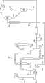
图1是一种回路反应器和聚合物回收系统的视图;Figure 1 is a view of a loop reactor and polymer recovery system;
图2是沿图1的线2--2的截面图,显示连续出料附属部件;Figure 2 is a cross-sectional view along
图3是沿图2的线3-3的截面图,显示连续出料组件中柱塞阀配置;Figure 3 is a cross-sectional view along line 3-3 of Figure 2, showing the configuration of the plunger valve in the continuous discharge assembly;
图4是所述连续出料组件切线位置的截面图;Fig. 4 is a sectional view of the tangent position of the continuous discharge assembly;
图5是回路反应器的肘管的侧视图,显示沉降支线和连续出料组件;Figure 5 is a side view of the elbow of the loop reactor showing the settling leg and continuous discharge assembly;
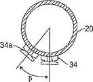
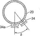
图6是沿图5的线6--6的截面图,显示两个连续出料组件的取向;Figure 6 is a cross-sectional view along
图7是显示另一个连续出料组件的取向的侧视图;Figure 7 is a side view showing the orientation of another continuous discharge assembly;
图8是叶轮机械的截面图;Fig. 8 is a sectional view of a turbomachine;
图9是显示回路反应器的另一种构造的视图,其中上面的段14a为180度的半圆,并且其中垂直部分至少是水平部分的两倍长,和Figure 9 is a view showing another configuration of a loop reactor in which the
图10是显示水平布置的更长轴的视图;Figure 10 is a view showing a longer axis arranged horizontally;
图11是下游的回收系统的视图;Figure 11 is a view of the downstream recovery system;
图12(a)和12(b)分别是一个旋风分离器的顶视图和侧视图。Figures 12(a) and 12(b) are top and side views, respectively, of a cyclone separator.
实施本发明的最佳方式Best Mode for Carrying Out the Invention
令人惊奇地,现已发现,在回路反应器中在惰性稀释剂存在下进行的烯烃聚合反应中,产物淤浆的连续出料使得反应器可以在高得多的固体浓度下操作。主要是乙烯聚合物在异丁烷稀释剂中的工业生产(过去)通常局限于37-40重量%的反应器中最大固体浓度。但是,已发现所述连续出料允许显著增加固体浓度。而且,因为所述连续出料附属部件被布置成选择性地从固体更浓缩的层中移除淤浆,与在从中取出产物的反应器中的含量相比,所述连续出料本身带来一定程度的固体含量的额外增加。因此,按照本发明,大于40重量%的浓度是可能的。在本申请中,催化剂的重量可忽略不计,因为尤其在采用负载在二氧化硅上的氧化铬时生产率极高。Surprisingly, it has now been found that in the polymerization of olefins in a loop reactor in the presence of an inert diluent, the continuous discharge of the product slurry allows the reactor to be operated at much higher solids concentrations. Commercial production (in the past) of mainly ethylene polymers in isobutane diluent has generally been limited to a maximum solids concentration in the reactor of 37-40% by weight. However, it has been found that the continuous discharge allows a significant increase in solids concentration. Moreover, because the continuous discharge attachment is arranged to selectively remove the slurry from a more concentrated layer of solids, the continuous discharge itself brings Some degree of additional increase in solids content. Concentrations of greater than 40% by weight are thus possible according to the invention. In this application, the weight of the catalyst is negligible because the productivity is extremely high especially when using chromium oxide supported on silica.
还令人惊奇地,现已发现,在较高的固体浓度下可以采用较为强烈的循环,即采用较高的循环速度。较高的固体浓度不是伴随的,但在高的循环速度下是可能的。确实,通过更强烈的循环结合连续出料,大于50重量%的固体浓度可以通过连续出料从反应器移除。例如,连续出料可以容易地允许在高5-6个百分点的条件下操作;即可以调节反应器以容易地以10%的幅度提高固体含量;并且更强烈的循环可容易地增加另外7-9个百分点,这使得反应器在50%以上。但是,因为连续出料被布置成从具有比平均固体浓度更高浓度的料流层取出淤浆,所以实际回收的产品具有比反应器淤浆平均值高约3个百分点(或更大)的浓度。这样,所述操作可以接近55的有效淤浆浓度。Surprisingly, it has also been found that at higher solids concentrations more intensive circulation, ie higher circulation speeds, can be employed. Higher solids concentrations are not concomitant, but possible at high circulation rates. Indeed, solids concentrations greater than 50% by weight can be removed from the reactor by continuous discharge by more intensive circulation combined with continuous discharge. For example, continuous discharge can easily allow operation at 5-6 percent higher; i.e., the reactor can be tuned to easily increase solids content in steps of 10 percent; and more intense circulation can easily add another 7-6 percent 9 percent, which puts the reactor above 50 percent. However, because the continuous discharge is arranged to withdraw the slurry from a stream layer having a higher than average solids concentration, the actual recovered product has a concentration of about 3 percent (or more) higher than the reactor slurry average. concentration. In this way, the operation can approach an effective slurry concentration of 55.
必须强调的是,在工业操作中,小至1个百分点的固体浓度的增加都是重要的。因此,从反应器中37-40的平均百分固体浓度到即使41都是重要的;由此,达到大于50确实非同寻常。It must be emphasized that in commercial operation, increases in solids concentrations as small as 1 percent are significant. Thus, going from an average percent solids concentration of 37-40 in the reactor to even 41 is significant; thus, reaching greater than 50 is indeed extraordinary.
本发明可应用于在回路反应器中产生聚合物产物淤浆和未反应的单体(在聚丙烯的情况下)或稀释剂(在聚乙烯的情况下未反应的单体和稀释剂)的任何烯烃聚合中。在聚丙烯的情况下,不使用稀释剂。适宜的烯烃单体是每分子具有至多8个碳原子、并且没有比4-位更接近双键的支链的1-烯烃。本发明特别适合于乙烯的均聚和乙烯与更高级1-烯烃如丁烯、1-戊烯、1-己烯、1-辛烯或1-癸烯的共聚。尤其优选的是乙烯与以乙烯和共聚单体的总重量计0.01至10重量%、或者0.01至5重量%、或者0.1至4重量%的更高级烯烃的共聚。或者,可以使用足够的共聚单体来给出聚合物中上述量的共聚单体引入。The present invention is applicable to production of polymer product slurry and unreacted monomer (in case of polypropylene) or diluent (unreacted monomer and diluent in case of polyethylene) in a loop reactor in any olefin polymerization. In the case of polypropylene, no diluent is used. Suitable olefin monomers are 1-alkenes having up to 8 carbon atoms per molecule and no branches closer to the double bond than the 4-position. The invention is particularly suitable for the homopolymerization of ethylene and the copolymerization of ethylene with higher 1-olefins such as butene, 1-pentene, 1-hexene, 1-octene or 1-decene. Especially preferred is the copolymerization of ethylene with 0.01 to 10 wt%, alternatively 0.01 to 5 wt%, alternatively 0.1 to 4 wt% higher olefin, based on the total weight of ethylene and comonomer. Alternatively, sufficient comonomer may be used to give the aforementioned amounts of comonomer incorporation in the polymer.
本发明可用于任何在液体介质中的淤浆聚合。本发明尤其可用于在产生的聚合物在聚合条件下大部分不溶解于其中的液体稀释剂中的烯烃聚合。最特别地,本发明可用于利用稀释剂以产生聚合物固体和液体稀释剂的淤浆的在回路反应器中进行的任何烯烃聚合。The present invention is applicable to any slurry polymerization in a liquid medium. The invention is particularly useful for the polymerization of olefins in liquid diluents in which the resulting polymer is largely insoluble under the conditions of polymerization. Most particularly, the invention is applicable to any olefin polymerization carried out in a loop reactor utilizing a diluent to produce a slurry of polymer solids and liquid diluent.
合适的稀释剂(与溶剂或单体相对)在本领域中是众所周知的,包括在反应条件下是惰性的并且是液体的烃。合适的烃包括异丁烷、丙烷、正戊烷、异戊烷、新戊烷和正己烷,异丁烷是特别优选的。Suitable diluents (as opposed to solvents or monomers) are well known in the art and include hydrocarbons which are inert and liquid under the reaction conditions. Suitable hydrocarbons include isobutane, propane, n-pentane, isopentane, neopentane and n-hexane, with isobutane being particularly preferred.
另外,在未反应的单体是用于聚合的液体介质的情况下,可以采用本技术。例如,在丙烯是液体介质并且惰性稀释剂不以任何实质的量存在的情况下,本技术可用于所述丙烯聚合。稀释剂仍然可以被用于催化剂。作为例证而非作为限制,将结合使用惰性稀释剂作为液体介质的聚乙烯工艺描述本发明,但应当理解,在单体被用作液体介质并取代以下描述中的稀释剂时也可以采用本发明。In addition, the present technique can be employed in the case where unreacted monomer is the liquid medium used for polymerization. For example, where propylene is the liquid medium and an inert diluent is not present in any substantial amount, the technique can be used for the propylene polymerization. Diluent can still be used for the catalyst. By way of illustration and not limitation, the invention will be described in connection with a polyethylene process using an inert diluent as the liquid medium, but it should be understood that the invention can also be employed when monomer is used as the liquid medium and replaces the diluent in the following description .
适宜的催化剂在本领域中是众所周知的。特别合适的是广泛公开的(例如在USP 2,825,721中公开的,该文件通过引用结合在此)在载体如二氧化硅上的氧化铬。这里提及二氧化硅载体意味着还包括任何已知的含二氧化硅的载体,例如二氧化硅-氧化铝、二氧化硅-氧化钛和二氧化硅-氧化铝-氧化钛。也可以使用任何其它已知的载体,如磷酸铝。本发明也适用于使用有机金属催化剂,包括本领域中常称为齐格勒催化剂(或齐格勒-纳塔催化剂)和茂金属催化剂的那些催化剂的聚合。Suitable catalysts are well known in the art. Particularly suitable are chromium oxides widely disclosed (for example in USP 2,825,721, which is hereby incorporated by reference) on supports such as silica. Reference herein to a silica support is meant to also include any known silica-containing supports such as silica-alumina, silica-titania and silica-alumina-titania. Any other known support such as aluminum phosphate may also be used. The present invention is also applicable to polymerizations using organometallic catalysts, including those commonly referred to in the art as Ziegler catalysts (or Ziegler-Natta catalysts) and metallocene catalysts.
现在参考附图,图1显示了一个回路反应器10,其具有垂直的段12、上部水平段14和下部水平段16。这些上部和下部的水平段定义了上部和下部的水平流动区。所述反应器通过由管12和夹套18形成的两管式换热器冷却。每一段都通过平滑的弯管或肘管20连接到下一段,由此提供基本上没有内部障碍的连续流动通道。聚合混合物借助于由马达24驱动的叶轮22(图8中所示)循环。单体、共聚单体(如果存在的话)和补充的稀释剂分别通过管线26和28加入,管线26和28可以在一个或多个位置直接进入反应器,或者可以如所示与冷凝的稀释剂循环管线30结合。催化剂通过催化剂加入装置32加入,该装置提供了用于催化剂加入的区域(位置)。用于连续排出中间产物淤浆的延长的中空附属部件笼统地由参考符号34指明。连续出料的机械结构34位于或相邻于一个下部的水平反应器环管段16的下游末端,并相邻于一个连接肘管20或在连接肘管20上。Referring now to the drawings, FIG. 1 shows a
或者,聚合物淤浆可以从所述回路移除至沉降支线,如USP4,424,341中所阐述的,该文件通过引用结合在此。取出的淤浆可以从所述沉降支线进入闪蒸管线并进入旋风分离器。所述闪蒸管线导管具有间接换热装置,例如闪蒸管线加热器。Alternatively, the polymer slurry may be removed from the circuit to a settling branch as described in USP 4,424,341 , which is hereby incorporated by reference. The withdrawn slurry may pass from the settling leg into a flash line and into a cyclone. The flash line conduit has an indirect heat exchange device, such as a flash line heater.
所述连续出料附属部件被显示为在所述回路反应器的一个下部水平段的下游末端,这是优选的位置。该位置可以是在接近在催化剂引入点之前料流转而向上的所述回路的最后一点的区域,以便使新鲜催化剂能够在其第一次经过出料点之前在反应器中有最大可能的时间。但是,所述连续出料附属部件可以位于任何段或任何肘管。The continuous discharge appendage is shown at the downstream end of a lower horizontal section of the loop reactor, which is the preferred location. This location may be an area close to the last point of the circuit where the flow turns upwards before the catalyst introduction point, so as to allow the maximum possible time for fresh catalyst in the reactor before it passes the exit point for the first time. However, the continuous discharge attachment may be located in any section or any elbow.
还有,所述连续出料附属部件连接到其上的反应器段可以具有较大的直径,以使物流慢下来并因此进一步允许物流分层,以至于出来的产物可以具有甚至更大的固体浓度。Also, the reactor section to which the continuous discharge appendage is connected may have a larger diameter to slow down the stream and thus further allow stratification of the stream so that the product coming out may have even larger solids concentration.
连续取出的中间产物淤浆通过导管36通入第一室,例如高压闪蒸室38。导管36包括环绕的导管40,该导管40被提供有加热的流体,该流体为闪蒸管线导管36中的淤浆材料提供间接加热。蒸发的稀释剂通过导管42离开闪蒸室38以进行进一步处理,所述处理包括通过使用循环冷凝器50的简单换热进行的冷凝,和经过循环稀释剂管线30返回至系统中,不需要压缩。循环冷凝器50可以利用在本领域中已知的任何条件下的本领域中已知的任何合适的换热流体。但是,优选使用在可以经济地提供的温度下的流体。对于该流体,适宜的温度范围是约32℉至约200℉,或约70℉至约100℉。(冷却塔水温是优选的,F但其它温度是可能的,所以我们应该拓宽范围)。聚合物颗粒被通过管线44从高压闪蒸室38中取出,以供使用本领域中已知的技术进一步处理。它们优选被通入低压闪蒸室46中,其后作为聚合物产品通过管线48被回收。分离的稀释剂通过压缩机47进入管线42。该高压闪蒸设计被广泛公开在Hanson和Sherk的USP 4,424,341中。在USP4,424,341中,提供了一种从包含聚合物固体在液体稀释剂中的淤浆的聚合流出液中回收聚合物固体的方法。该方法包括加热所述流出液,并通过使已加热的流出液暴露在第一闪蒸步骤中的压力降下来蒸发所述已加热的流出液中的稀释剂。在第一闪蒸步骤中已加热的流出液的压力和温度应使得大部分的稀释剂被蒸发,并且所述蒸气可以通过与温度在约40℉至约130℉范围内的流体热交换而在没有压缩的情况下被冷凝。所述稀释剂蒸气被与聚合物固体分开,然后通过与温度在约40℉至约130℉范围内的流体热交换而在没有压缩的情况下被冷凝。来自第一闪蒸步骤的聚合物固体然后经受低压闪蒸步骤的处理,以蒸发另外的剩余的稀释剂(如果存在的话),并且稀释剂蒸气与聚合物固体被分开。The continuously withdrawn intermediate product slurry is passed through
令人惊奇地,现已发现,所述连续出料不仅允许上游在反应器中有更高的固体浓度,而且允许更好地操作所述高压闪蒸,由此使得大部分被取出的稀释剂被闪蒸掉,并在没有压缩的情况下被回收。事实上,70-90%的稀释剂通常可以以此方式回收。优选地,90-95%或更多,或者90-99%或更多,或者90-99.9%或更多的稀释剂被以此方式保留。因为所述物流是连续的而不是断续的,所以闪蒸管线加热器可以更好地工作。还有,所述闪蒸管线可以设计为具有适宜量的压力降,以获得高的速率和高的传热系数,并限制最大流量。在这种设计中,CTO出口压力将高于其它位置可能的压力。在连续出料阀(其调控离开反应器的连续物流的速率)后的压力降不如在沉降支线的触发阀(firingvalve)后的压力降剧烈。采用沉降支线,闪蒸管线中的淤浆温度更高,并且更少的热量被传递到淤浆中,使得闪蒸管线加热器不太有效。Surprisingly, it has now been found that the continuous discharge not only allows a higher solids concentration upstream in the reactor, but also allows better operation of the high pressure flash, whereby most of the diluent withdrawn is flashed off and recycled without compression. In fact, 70-90% of the diluent can usually be recovered in this way. Preferably, 90-95% or more, or 90-99% or more, or 90-99.9% or more of the diluent is retained in this manner. Flash line heaters work better because the stream is continuous rather than intermittent. Also, the flash line can be designed with an appropriate amount of pressure drop to achieve high velocity and high heat transfer coefficient, and to limit the maximum flow. In this design, the CTO outlet pressure will be higher than possible elsewhere. The pressure drop after the continuous discharge valve (which regulates the rate of the continuous stream leaving the reactor) is not as drastic as the pressure drop after the firing valve of the settling leg. With a settling leg, the temperature of the slurry in the flash line is higher and less heat is transferred to the slurry, making the flash line heater less effective.
或者,闪蒸管线加热器可以将物料排放到分离蒸发的稀释剂与聚合物固体的旋风分离器中。所述旋风分离器可以连接到闪蒸罐,或者如图11中所示连接到粉料接收器,这将在以下更详细地描述。Alternatively, the flash line heater can discharge the material to a cyclone separator that separates the evaporated diluent from the polymer solids. The cyclone can be connected to a flash tank, or as shown in Figure 11, to a fines receiver, which will be described in more detail below.
图2详细描述了带有连续出料机械结构34的肘管20。所述连续出料机械结构包括出料圆柱体52、淤浆取出管线54、紧急截止阀55、用于控制流量的比例马达阀58和冲洗管线60。反应器“液体”全满地运转。因为溶解的单体,所以所述液体具有微小的可压缩性,由此可以用阀对所述液体全满的系统控制压力。稀释剂输入通常保持不变,比例马达阀58被用来控制连续取出的速度,以维持总的反应器压力在指定的设定点之内。FIG. 2 details the
图3取自图2的剖面线3--3,更详细地显示了具有与其结合的连续出料机械结构34的平滑曲线或肘管20,所述肘管20因此是带有附属部件的肘管。如图所示,所述机械结构包括出料圆柱体52,所述出料圆柱体52在此例中与肘管的外表面切线呈直角连接。从圆柱体52分出的是淤浆取出管线54。配置在出料圆柱体52内的是柱塞阀62,其起到两方面的作用。首先,如果出料圆柱体被聚合物淤塞,所述柱塞阀62提供了用于出料圆柱体的简单且可靠的清洁机械。其次,它可以起到用于整个连续出料组件的简单且可靠的截止阀的作用。Figure 3, taken from section line 3--3 of Figure 2, shows in more detail the smooth curve or
图4显示了出料圆柱体52的一个优选的连接取向,其中该圆柱体切向固定在肘管20的弯曲部分,并恰好在淤浆流转向上之前的点上。该开口在内表面上是椭圆型的。可以进一步扩大,以改进固体物的出料。Figure 4 shows a preferred attachment orientation for the
图5显示了4件事情。首先,它显示了出料圆柱体52有角度的取向。该出料圆柱体被显示为与(1)垂直于水平段16的中心线,且(2)位于水平段16的下游末端的平面呈一角,即α。与该平面的所述角取自所述平面的下游方向。该角的顶点是肘管半径的中心点,如图5中所示。所述平面可以被描述为水平段的横截面。这里所描绘的角度为约24度。第二,它显示了多个连续出料附属部件34和34a。第三,它显示了在下部段16的垂直中心线平面上取向的一个附属部件34,和位于与所述平面呈一定角度处的另一个附属部件34a,这将在图6中更详细地显示。最后,它显示了连续出料附属部件34与用于间歇出料的沉降常规支线64(如果需要的话)的组合。Figure 5 shows 4 things. First, it shows the angular orientation of the
在本发明的另一个实施方案中,提供了一种聚合方法。该方法包括:1)在回路反应区中,在液体稀释剂中聚合至少一种烯烃单体,以产生流体淤浆,其中所述流体淤浆包含液体稀释剂和固体烯烃聚合物颗粒;2)通过交替地进行以下步骤,取出包含取出的液体稀释剂和取出的聚合物颗粒的流体淤浆:a)允许流体淤浆沉降到至少一个沉降区中,和其后从所述沉降区中取出一批如此沉降的淤浆作为所述方法的中间产物,随后关闭在所述沉降区底部的阀;和b)其后连续地取出包括取出的液体稀释剂和取出的固体聚合物颗粒的流体淤浆作为所述方法的中间产物。在步骤b)中,可以在启动过程中调节反应器条件,以提升反应器的固体含量至少10%。In another embodiment of the present invention, a polymerization method is provided. The process comprises: 1) polymerizing at least one olefin monomer in a liquid diluent in a loop reaction zone to produce a fluid slurry, wherein the fluid slurry comprises liquid diluent and solid olefin polymer particles; 2) The fluid slurry comprising the withdrawn liquid diluent and the withdrawn polymer particles is withdrawn by alternately performing the following steps: a) allowing the fluid slurry to settle into at least one settling zone, and thereafter withdrawing a a batch of the slurry thus settled as an intermediate product of the process, followed by closing of a valve at the bottom of the settling zone; and b) thereafter continuously withdrawing the fluid slurry comprising withdrawn liquid diluent and withdrawn solid polymer particles as an intermediate product of the process. In step b), the reactor conditions may be adjusted during start-up to increase the solids content of the reactor by at least 10%.
从相对尺寸可以看出,所述连续出料圆柱体比常规的沉降支线小得多。然而3个2英寸ID的连续出料附属部件可以与14个8英寸ID的沉降支线移除一样多的淤浆产物。这是有意义的,因为在目前的15,000-18,000加仑容量的大型商业化回路反应器中,使用6个8英寸的沉降支线。增加沉降支线的尺寸是不希望的,因为制造可靠的更大直径的阀门有困难。如以前所指出的,使管的直径加倍将会使体积增加到4倍,并且在没有足够的空间来容易地布置4倍数量的沉降支线的情况下将使问题简化。还有,与所述较小的连续出料装置相比,更大量的较大的沉降支线更加昂贵并且需要更复杂的控制方案。因此,本发明使得更大的、更有效的反应器的操控变得可行。本发明使得20,000加仑或更大、甚至30,000加仑或更大的反应器成为可能。通常,所述连续出料圆柱体可以具有在1英寸至小于8英寸范围内的标称内径。优选它们具有约2-3英寸的内径。还有,所述较小的连续出料圆柱体通常比更大量的和更大直径的沉降支线危险小。这是因为,如果发生了管道破损,将涉及较小的管线,并且因此涉及较小的烃泄漏速率。还有,所述连续出料圆柱体具有较小的堵塞倾向,因此较小可能会涉及危险的维护操作。As can be seen from the relative dimensions, the continuous discharge cylinder is much smaller than conventional settling legs. However three 2 inch ID continuous discharge appendages can remove as much slurry product as 14 8 inch ID settling legs. This makes sense because in current large commercial loop reactors of 15,000-18,000 gallon capacity, six 8 inch settling legs are used. Increasing the size of the settling leg is undesirable because of difficulties in making reliable larger diameter valves. As previously pointed out, doubling the diameter of the tube will quadruple the volume and will simplify the problem if there is not enough space to easily arrange 4 times as many settling legs. Also, a greater number of larger settling legs is more expensive and requires a more complex control scheme than the smaller continuous discharge. Thus, the present invention enables the handling of larger, more efficient reactors. The invention enables reactors of 20,000 gallons or larger, even 30,000 gallons or larger. Typically, the continuous discharge cylinder may have a nominal inner diameter in the range of 1 inch to less than 8 inches. Preferably they have an inside diameter of about 2-3 inches. Also, the smaller continuous discharge cylinders are generally less dangerous than larger and larger diameter settling legs. This is because, if a pipeline break occurs, there will be less pipeline involved, and thus a smaller hydrocarbon leakage rate. Also, the continuous discharge cylinder has less tendency to clog and thus less likely to involve dangerous maintenance operations.
图6沿图5的剖面线6--6取得,并且显示了连接的出料圆柱体34a,其在与含反应器中心线的垂直平面呈角度β取向的平面内。含反应器中心线的垂直平面可以被称为反应器的垂直中心平面。该角度可以取自所述平面的任一侧或两侧,如果β不等于0。所述角的顶点位于反应器的中心线。该角包含在垂直于反应器中心线的平面内,如图6中所示。Figure 6 is taken along
应当注意到,这里存在三种取向的概念。第一种是连接取向,即如图4中的切向和图2或7中的垂直方向,或者在这两种极限0和90度之间的任何角度。第二种为关于所述连接在肘管曲线以上有多远的由角度α(图5)所表示的取向。该角度可以是0-60度的任何角度,但优选0-40度,更优选0-20度。第三种是从纵向段的中心平面偏离的角度β(图6)。该角度可以是0-60度,优选0-45度,更优选0-20度。It should be noted that there are three concepts of orientation here. The first is the connection orientation, ie tangential as in Figure 4 and vertical as in Figures 2 or 7, or any angle between these two limits of 0 and 90 degrees. The second is the orientation represented by the angle α (Fig. 5) with respect to how far above the elbow curve the connection is. The angle may be any angle from 0-60 degrees, but preferably 0-40 degrees, more preferably 0-20 degrees. The third is the angle β of the deviation from the center plane of the longitudinal section (Fig. 6). The angle may be 0-60 degrees, preferably 0-45 degrees, more preferably 0-20 degrees.
图7显示了一个实施方案,其中所述连续出料圆柱体52具有垂直的连接取向,为0的α取向(固有的,因为它是在末端,但仍然在直线部分上),和为0的β取向,即它正在下部水平段16的垂直中心线平面上。Figure 7 shows an embodiment in which the
图8详细显示了用于沿淤浆流动路径连续驱动淤浆的叶轮装置22。如在该实施方案中可以看出的那样,所述叶轮是在管的稍微扩大的部分,该部分起到循环反应物的推动区的作用。在标称直径为2英尺、总流动通道长度为约950英尺、使用异丁烷来主要制造乙烯聚合物的反应器中,优选操作所述系统,以在所述推动区的上游端和下游端之间产生至少18psig、优选至少20psig、更优选至少22psig的压差。压差可以高达50psig或更大。这可以通过控制叶轮的旋转速度,降低叶轮与泵壳的内壁之间的间隙,或者通过使用更强劲的叶轮设计来实现,如本领域中已知的那样。这种较高的压差也可以通过使用至少一个附加的泵来产生。Figure 8 shows in detail the impeller arrangement 22 for continuously driving the slurry along the slurry flow path. As can be seen in this embodiment, the impeller is in a slightly enlarged portion of the tube which acts as a push zone for the circulating reactants. In a reactor having a nominal diameter of 2 feet and a total flow path length of about 950 feet, using isobutane to primarily make ethylene polymer, it is preferred to operate the system so that at the upstream and downstream ends of the push zone A pressure differential of at least 18 psig, preferably at least 20 psig, more preferably at least 22 psig is created therebetween. The differential pressure can be as high as 50 psig or greater. This can be accomplished by controlling the rotational speed of the impeller, reducing the clearance between the impeller and the inner wall of the pump casing, or by using a more robust impeller design, as is known in the art. This higher differential pressure can also be generated by using at least one additional pump.
通常,对于标称直径为24英寸的反应器,所述系统被运转以产生以每单位反应器长度的压力损失表示至少0.07,通常0.07-0.15英尺淤浆高度的压力降/英尺反应器长度的压差。优选地,该每单位长度的压力降对于直径为24英寸的反应器来说为0.09-0.11。对于更大的直径,需要更高的淤浆速率和更高的每单位反应器长度的压力降。这假定淤浆的密度通常为约0.5-0.6。Typically, for a reactor having a nominal diameter of 24 inches, the system is operated to produce a pressure drop expressed as pressure loss per unit reactor length of at least 0.07, typically 0.07-0.15 feet of slurry height per foot of reactor length differential pressure. Preferably, the pressure drop per unit length is 0.09-0.11 for a 24 inch diameter reactor. For larger diameters, higher slurry velocities and higher pressure drops per unit reactor length are required. This assumes that the density of the slurry is typically about 0.5-0.6.
图9显示了为180度半圆的上部段,其是优选的结构。垂直段长度为水平段长度的至少2倍,通常约7-8倍。例如,在流动路径长度中,垂直流动路径可以是190-225英尺,而水平段为25-30英尺。除了这里所描述的4个环管和图1中所描述的8个环管以外,可以采用任何数量的环管,但通常使用4个或8个环管。提到标称2英尺的直径意味着内径为约21.9英寸。流动长度通常大于500英尺,通常大于900英尺,约940-2000英尺是非常令人满意的。Figure 9 shows the upper section being a 180 degree semicircle, which is the preferred configuration. The length of the vertical segment is at least 2 times the length of the horizontal segment, usually about 7-8 times. For example, the vertical flow path may be 190-225 feet and the horizontal section 25-30 feet in flow path length. Any number of collars may be used other than the 4 collars described here and the 8 collars depicted in Figure 1, but typically 4 or 8 collars are used. Reference to a nominal 2 foot diameter means an internal diameter of about 21.9 inches. Flow lengths are generally greater than 500 feet, usually greater than 900 feet, with about 940-2000 feet being very satisfactory.
图10显示了包括水平段和弯曲的和直的垂直段的水平回路反应器11。所述垂直段定义了垂直流动的区域。该反应器通过由管12和夹套18形成的两管式换热器冷却。如图所示,每个直的垂直段通过平滑的弯管或肘管20连接到水平段上,由此提供基本上没有内部障碍的连续流动通道。如图所示,弯曲的垂直段是在2个相邻的水平段之间延伸的180度的半圆,其是另一种理想的结构。或者,所述垂直段可以全部是半圆或直管,或任何希望的组合,只要垂直段连通到水平段即可。Figure 10 shows a horizontal loop reactor 11 comprising a horizontal section and curved and straight vertical sections. The vertical segments define areas of vertical flow. The reactor is cooled by means of a two-tube heat exchanger formed by
在图10中,水平段是垂直段的至少2倍长度,通常约7-8倍长度。例如,水平段流动通道长度可以是190-225英尺,垂直段流动通道长度可以是25-30英尺。除了这里所描述的4个环管以外,可以采用任何数量的环管,但通常使用4个或8个环管。提到标称2英尺的直径意味着内径为约21.9英寸。流动长度通常大于500英尺,通常大于900英尺,约940-2000英尺是非常令人满意的。In Figure 10, the horizontal segment is at least twice as long as the vertical segment, typically about 7-8 times as long. For example, the horizontal section flow channel length may be 190-225 feet and the vertical section flow channel length may be 25-30 feet. Any number of collars may be used other than the 4 collars described here, but typically 4 or 8 collars are used. Reference to a nominal 2 foot diameter means an internal diameter of about 21.9 inches. Flow lengths are generally greater than 500 feet, usually greater than 900 feet, with about 940-2000 feet being very satisfactory.
连续出料附属部件34显示为在所述回路反应器的一个水平段的下游末端。该位置可以是在接近在催化剂引入点之前料流转而向上的所述回路的最后一点的区域,以便使新鲜催化剂能够在其第一次经过出料点之前在反应器中有最大可能的时间。但是,所述连续出料附属部件可以位于任何段或任何肘管上。A
图10的水平回路反应器可以用作图1和9的垂直回路反应器10的替代方案,并且可以与本发明的任何其它特征组合使用。The horizontal loop reactor of Figure 10 can be used as an alternative to the
图11显示了下游回收系统的一种可选择的布置,该回收系统用于分离在从聚合反应器中取出的中间产物淤浆中的固体聚合物颗粒和稀释剂。在中间产物淤浆被从反应器中取出后,其经过一个或多个导管36。所述导管36通常包括环绕导管40,该环绕导管40被提供有已加热的流体,由此形成给经过闪蒸管线36的淤浆提供间接加热的闪蒸管线加热器。该闪蒸管线加热器加热反应器流出液,或至少防止所述流出液的过度冷却。所述环绕导管40可以具有与闪蒸管线36基本相同的长度。在某些利用闪蒸管线加热器的系统中,一些或全部的稀释剂将在被引入闪蒸室28之前在闪蒸管线36中闪蒸。但是,术语“闪蒸室”和“闪蒸罐”仍经常被用于闪蒸管线以后的罐,在此蒸发的稀释剂与聚合物固体分离。“闪蒸罐”或“闪蒸室”仍然被使用,即使在闪蒸罐中几乎没有或没有闪蒸,如果全部或基本上全部的稀释剂在闪蒸管线中被蒸发的话。在闪蒸管线在较高压力下排放并且没有下游干燥装置的某些设计中,闪蒸管线被设计成在进入其之后的罐时几乎没有或没有压力降,而不是伴随在管线中的高速流动和在所述物流进入所述罐中时改变其流速。还可以想到,在被取出的材料到达所述闪蒸管线之后的罐时之前全部或基本全部的稀释剂被蒸发。Figure 11 shows an alternative arrangement of a downstream recovery system for the separation of solid polymer particles and diluent in the intermediate product slurry withdrawn from the polymerization reactor. After the intermediate product slurry is withdrawn from the reactor, it passes through one or
导管36可以被环绕导管40的几个部分环绕,以提供对闪蒸管线加热的更好的控制。例如,闪蒸管线加热器可以具有20个或更多个环绕导管部分,每个部分的长度为20英尺或更长。在控制温度时,所述闪蒸管线加热器的各部分可以共享一个蒸汽控制器,或者它们可以具有各自的蒸汽控制器。如USP 4,424,341中所公开的,应当给环绕导管40提供低压蒸汽,以避免使经过闪蒸管线导管36的固体聚合物颗粒熔化。
中间产物淤浆通过导管36进入下游的分离装置。例如,闪蒸管线36可以通入高压闪蒸室38中,如图1中所示。作为另一个实例,闪蒸管线加热器可以通入“漏斗”66和/或旋风分离器68中,如图11中所示。所述漏斗66提供了一个区域,在此在多个闪蒸管线36内的材料可以被混合以形成包含稀释剂和固体聚合物颗粒的单一料流。这样,该漏斗不需要具有大于底部开口的倾斜开口(如家用漏斗那样),而可以是有助于在入口的一个或多个单独的料流在出口融合成为一个合并的料流的任何形状或尺寸。该漏斗可用于将所述料流成型为以下所描述的标准旋风分离器入口尺寸。还有,由于闪蒸管线中的速度有时候非常高,所述漏斗或过渡部件可以被用来使所述淤浆减慢至对用于旋风分离器中来说可接受的速度。另外,可以设计所述漏斗,使得有一个以上的进入旋风分离器的入口,或者使得可以使用一个以上的旋风分离器。The intermediate product slurry is passed through
从漏斗66出来,所述单一物流可以被进料到旋风分离器68中,在此蒸发的稀释剂及其它蒸气组分被与固体聚合物颗粒分开。旋风分离器68通过离心力分离蒸气和固体。旋风分离器被广泛用于集尘以及很多其它应用中。(参见Perry’s Chemical Engineers’Handbook,第7版17-27页,通过引用将其结合在此。)Perry’s中的举例说明并不代表用于本方法中的高效旋风分离器。携带颗粒的气体在一个或多个点切向进入圆柱形或圆锥型室中,并通过中心开口离开。由于其惯性,所述颗粒往往向分离器的外壁移动,从那它们被导向接收器中。旋风分离器类似于沉降室,除了重力加速度至少部分被离心加速度所替代以外。在旋风分离器中,气体路径涉及一个双旋涡,在外部气体螺旋向下和在内部气体螺旋向上。气体在旋风分离器的顶部离开,而固体在旋风分离器的底部离开。From
旋风分离器68可以在类似于以上所述的高压闪蒸室所采用的那些的压力和温度下运转。又例如,旋风分离器68可以在通常用于中压闪蒸室,例如在Hanson等人的USP 4,424,341(该文件已经通过引用结合在本文中)中所阐述的两段式闪蒸系统的中压闪蒸室的压力和温度下运转。优选地,所述旋风分离器或旋风分离区可以在100-1500psia(7-105kg/cm2)、或者125-275psia(8.8-19kg/cm2)、或者150-250psia(10.5-17.6kg/cm2)、或者140-190psia(9.8-13.4kg/cm2)、或者约170psia(11.9kg/cm2)的压力下运转。所述旋风分离器或旋风分离区可以在100-250℉(37.8-121℃)、优选130-230℉(54.4-110℃)、更优选150-210℉(65.6-98.9℃)或170-200℉(76.6-93.3℃)的温度下运转。所述较窄的范围尤其适合于使用1-己烯共聚单体和异丁烷稀释剂的聚合,而所述较宽的范围通常适合于更高级1-烯烃共聚单体和烃稀释剂。
通过将闪蒸管线导向旋风分离器,可以实现更好的分离效率,并且基本上所有的固体都可以与顶空的蒸气流分开。完全的烃蒸气分离发生在清洗塔中。所述旋风分离器可以连接到闪蒸罐,或如图11中所示连接到粉料接收器70。因为大部分的蒸气被旋风分离器68分离,所以粉料接收器70可以比过去使用的闪蒸室或闪蒸气体分离器小。例如,一个典型的粉料接收器(接收区)的容积可以在33,675加仑(13’×28’加上锥体)的范围内,而所述粉料接收器是约13,500加仑(大致尺寸为10’×20’加上锥体),而两者都被设计为容纳约44,000磅从反应区排出并在回收系统中处理的中间聚合物产物。这是用于容积为35,500加仑的回路反应器的粉料接收器系统。所述粉料接收器70可以更小,因为几乎没有或没有空间要被用于分离气体和粉料。另一个优点在于通常不需要从旋风分离器引出的下行线(run down line)。By directing the flash line to the cyclone, better separation efficiency can be achieved and essentially all solids can be separated from the headspace vapor stream. Complete hydrocarbon vapor separation occurs in the scrubbing column. The cyclone can be connected to a flash tank, or as shown in FIG. 11 to a
蒸发的稀释剂通过导管72离开旋风分离器68以进行进一步处理,所述处理可以包括经过闪蒸气体过滤器74,在此细粉与闪蒸气体被分开。使用循环阀76a和76b将所述细粉排出过滤器74。所述闪蒸气体从过滤器74的顶部离开。所述闪蒸气体可以通过间接换热或通过压缩而被冷凝,并再循环至聚合反应器或相关系统。聚合物颗粒被从粉料接收器70取出并被送入粉料室78。所述粉料室78位于粉料接收器70之后,或更具体而言,在控制粉料接收器出口的控制阀80之后。控制阀80可以是位于粉料室78上游的循环球阀,而第二循环球阀82可以位于粉料室78的下游。粉料室78可以起到下降室(let down chamber)的作用,以降低从粉料接收器70转移的材料的压力。Vaporized diluent exits
所述循环阀这样操作,使得顶阀开启时底阀关闭。在此期间,粉料室78装填来自粉料接收器70的聚合物固体,至需要的水平或聚合物固体量,不超过最大允许容量。优选将粉料室完全充满。改变阀循环重复的速度,以控制粉料接收器70中粉料的水平。当达到需要的水平或量时,顶阀80关闭并且底阀82打开,聚合物固体被转移到相对低压的容器,例如清洗塔中。按照需要重复这些步骤,以将所述材料从粉料接收器70转移到清洗塔。可以将控制器连接到所述第一阀和所述第二阀,并且所述控制器可以被用于交替开启每一个阀。The circulation valve is operated such that the top valve is open while the bottom valve is closed. During this time, the
优选地,所述循环阀控制器可以被用于在闪蒸室的底部保持恒定水平的中间产物聚合物。这将给产物聚合物中的稀释剂时间,以从颗粒内部扩散至表面并蒸发。还有,在闪蒸室中保持一定水平可以给所述循环阀一个“聚合物密封”,使得在阀座磨损或不能完全将高压区气体与低压区密封隔开(但仍然挡住大部分聚合物)时,任何从高压区泄漏到低压区的高压气体不得不穿过颗粒之间空隙空间的弯曲路径。这减慢了高压气体向低压区的泄漏。这两者有助于改进在无压缩下通过冷凝回收高压闪蒸气体的效率。也可以使用操控第一和第二阀以使所述阀不同时打开的其它适宜的装置。Preferably, the recycle valve controller may be used to maintain a constant level of intermediate polymer at the bottom of the flash chamber. This will give the diluent in the product polymer time to diffuse from the interior of the particle to the surface and evaporate. Also, maintaining a certain level in the flash chamber can give the recycle valve a "polymer seal" where the valve seat wears or doesn't completely seal off the high pressure zone gas from the low pressure zone (but still blocks most of the polymer ), any high-pressure gas that leaks from a high-pressure region to a low-pressure region has to travel a tortuous path through the interstitial spaces between particles. This slows down the leakage of high pressure gas into low pressure areas. Both help to improve the efficiency of high pressure flash gas recovery by condensation without compression. Other suitable means of manipulating the first and second valves so that the valves do not open simultaneously may also be used.
所述循环阀可以这样配置和操作,使得聚合物固体的停留时间保持在需要的水平。聚合物固体的停留时间优选保持在基本上为0至2分钟。或者,聚合物固体的停留时间优选保持在10秒钟至30分钟。或者,聚合物固体的停留时间优选保持在30至90分钟,或30至120分钟。The recycle valve can be configured and operated such that the residence time of polymer solids is maintained at the desired level. The residence time of polymer solids is preferably maintained at substantially 0 to 2 minutes. Alternatively, the residence time of the polymer solids is preferably maintained at 10 seconds to 30 minutes. Alternatively, the residence time of the polymer solids is preferably maintained at 30 to 90 minutes, or 30 to 120 minutes.
通过在中压区中维持需要水平的固体烯烃聚合物颗粒,人们可以控制聚合物固体的停留时间,该停留时间为聚合物颗粒在中压区中所花时间的平均量。聚合物固体停留时间的增加允许更多的稀释剂(包括更多的夹带的稀释剂)从聚合物固体中闪蒸出来和/或与聚合物固体分离,由此提高离开所述区域的聚合物的纯度和可加工性。此外,通过在中压区中维持需要水平的聚合物固体,可以在所述区域与下游设备之间产生压力密封。另外,由于不需要使用开/关阀而在中压区和清洗区之间提供压力密封,操作和维持成本降低。还有,可以消除对单独粉料室的需要。所述压力密封可以依赖于聚合物固体的水平,以限制气体或液体(如果存在的话)稀释剂流出所述中压区。聚合物固体颗粒可以基本上封闭掉大部分稀释剂可获得的流动通道(横截面)。虽然如此,可以想到,通过相邻颗粒之间的小间隙,少量的流动路径是可以得到的。这种小的连续流可能会降低稀释剂在中压区中的最终回收效率。By maintaining a desired level of solid olefin polymer particles in the medium pressure zone, one can control the residence time of the polymer solids, which is the average amount of time the polymer particles spend in the medium pressure zone. The increase in polymer solids residence time allows more diluent (including more entrained diluent) to flash off from and/or separate from the polymer solids, thereby increasing the polymer solids exiting the zone. purity and processability. Furthermore, by maintaining the desired level of polymer solids in the medium pressure zone, a pressure seal can be created between that zone and downstream equipment. In addition, operating and maintenance costs are reduced since on/off valves are not required to provide a pressure seal between the medium pressure zone and the purge zone. Also, the need for a separate powder chamber can be eliminated. The pressure seal may rely on the level of polymer solids to restrict gaseous or liquid (if present) diluent from flowing out of the medium pressure zone. The polymeric solid particles can substantially close off most of the flow paths (cross-sections) available to the diluent. Nonetheless, it is conceivable that a small number of flow paths are available through small gaps between adjacent particles. This small continuous flow may reduce the final recovery efficiency of the diluent in the medium pressure zone.
使固体从高压闪蒸罐下降至低压闪蒸罐或清洗塔的另一种方法是使用节流阀,优选使用V形缺口的球阀。通过可变的开启面积,所述V形缺口球阀简单地节流气体和固体的流动,并可以被调节以在高压闪蒸罐中保持恒定的固体水平。这样的一个阀可以代替两个循环阀和粉料室78,并且更小,所以其比两个循环阀更便宜。因为它的移动比循环阀少,阀上的磨损率远比循环阀上的磨损率小,所以维护减少。还有,其稳定的操作减少了下游设备的压力波动,以至于所述设备可以更始终如一地运转,并且它们的阀不用不停地对变化的上游压力做出反应。所述单一V形缺口球阀或其它适宜的阀(例如带有增加的用于隔离目的的球阀的旋转阀)利用了上述的聚合物密封原理,所以所述阀不必应付高压区和低压区之间的全部压力降。选择两个压力区之间管线的长度和直径,以控制经过所述阀的气体泄漏率、所述阀经历的压力和所述两个阀之间的距离。Another method of descending the solids from the high pressure flash tank to the low pressure flash tank or purge column is to use a throttling valve, preferably a V-notch ball valve. With a variable opening area, the V-notch ball valve simply throttles the flow of gas and solids and can be adjusted to maintain a constant solids level in the high pressure flash tank. Such one valve can replace two recirculation valves and
从粉料室78出来,聚合物颗粒可以被送入低压分离室或清洗塔。现已发现,所述连续出料不仅允许上游反应器中有更高的固体浓度,而且允许更好地运转闪蒸管线加热器和旋风分离器,由此允许基本上全部取出的稀释剂在闪蒸管线中被蒸发并在旋风分离器中被分离。From the
图12(a)和12(b)分别显示了一种用于本发明方法和装置中的旋风分离器的顶视图和侧视图。用于本发明方法的旋风分离器可以被构造为稍微不同于图12(a)和12(b)中所示的结构。例如,对于非常高效率的旋风分离器而言,顶视图不必是同心圆圈。又例如,所述旋风分离器的底可以更大或被切掉,以提供非常大的底部出口。所述旋风分离器通过旋风分离器入口84接收来自回路反应器的流体物流。旋风分离器入口84可以是任何的形状,但通常是矩形的,并且其尺寸为垂直方向上比水平方向上更长。旋风分离器入口84将流体物流排入旋风分离器的上部86。通过将所述流体物流切向地排入一个罐中,发生了增强的分离作用,即使所述罐严格地说不是旋风分离器罐,并且这种排料通常优于垂直方式的排料。所述流体往下螺旋地向旋风分离器的下部88行进。固体与蒸气通过离心力分开。分开的固体从固体出口90离开,分离的蒸气从蒸气出口92离开,该出口可以向旋风分离器中延伸一段距离。在图12中,Dc是旋风分离器的上部的直径。Bc是入口宽度,Hc是入口高度。Lc是旋风分离器的上面部分的长度,Zc是旋风分离器下面逐渐变细的部分的长度。图12中旋风分离器的相对尺寸为任选的。-Fisher-Klosterman通常是高效旋风分离器选择的提供者,并且可以参考它们的文献来获得结构信息。Figures 12(a) and 12(b) show a top view and a side view, respectively, of a cyclone separator useful in the method and apparatus of the present invention. Cyclone separators used in the process of the present invention may be configured slightly differently than those shown in Figures 12(a) and 12(b). For example, for a very efficient cyclone separator, the top view need not be concentric circles. As another example, the bottom of the cyclone separator may be larger or cut away to provide a very large bottom outlet. The cyclone receives the fluid stream from the loop reactor through
表1显示了闪蒸管线切向进入的典型闪蒸室的估计的性能。给出了头顶进料旋风分离器中粉料的固体量和颗粒尺寸分布。Table 1 shows the estimated performance of a typical flash chamber with tangential entry of the flash line. The solids content and particle size distribution of the powder in the overhead feed cyclone are given.
表1Table 1

表2显示了旋风分离器和粉料接收器布置的估计的性能。显示了进料到闪蒸气体过滤器的固体的颗粒尺寸分布。Table 2 shows the estimated performance of the cyclone separator and fines receiver arrangement. The particle size distribution of solids fed to the flash gas filter is shown.
表2Table 2

实施例Example
使用四个垂直腿式聚合反应器来聚合乙烯和1-己烯,该反应器使用在M51879/FAB壳中的26英寸的Lawrence Pumps Inc.的泵式叶轮D51795/81-281。该泵与给出不太强烈循环的24英寸泵(0.66英尺的压力降对0.98英尺的压力降)进行比较。然后这与相同的更强烈的循环和图5的参考符号34所示类型的连续出料组件相比较。结果如下所示。Ethylene and 1-hexene were polymerized using four vertical legged polymerization reactors using a 26 inch Lawrence Pumps Inc. pump impeller D51795/81-281 in a M51879/FAB shell. This pump was compared to a 24 inch pump which gave less intense circulation (0.66 ft pressure drop vs. 0.98 ft pressure drop). This is then compared to the same more intense circulation and continuous discharge assembly of the type indicated by
表3table 3
尽管为了举例说明的目的已详细描述了本发明,但是本发明不应被理解为局限于所述说明,而是希望覆盖其精神和范围内的所有变化。While the invention has been described in detail for purposes of illustration, the invention should not be construed as limited to the description but is intended to cover all changes within its spirit and scope.
Claims (24)
Translated fromChineseApplications Claiming Priority (2)
| Application Number | Priority Date | Filing Date | Title |
|---|---|---|---|
| US10/699,095US20040136881A1 (en) | 1997-07-15 | 2003-10-31 | Separation of polymer particles and vaporized diluent in a cyclone |
| US10/699,095 | 2003-10-31 |
Publications (2)
| Publication Number | Publication Date |
|---|---|
| CN1886432A CN1886432A (en) | 2006-12-27 |
| CN100532401Ctrue CN100532401C (en) | 2009-08-26 |
Family
ID=34573276
Family Applications (1)
| Application Number | Title | Priority Date | Filing Date |
|---|---|---|---|
| CNB2004800352062AExpired - Fee RelatedCN100532401C (en) | 2003-10-31 | 2004-10-15 | Separation of polymer particles and evaporated diluent in a cyclone |
Country Status (7)
| Country | Link |
|---|---|
| US (1) | US20040136881A1 (en) |
| EP (2) | EP2993193B1 (en) |
| CN (1) | CN100532401C (en) |
| BR (1) | BRPI0415911B1 (en) |
| CA (1) | CA2544150C (en) |
| ES (1) | ES2562491T3 (en) |
| WO (1) | WO2005044871A1 (en) |
Families Citing this family (33)
| Publication number | Priority date | Publication date | Assignee | Title |
|---|---|---|---|---|
| CA2471048C (en) | 2002-09-19 | 2006-04-25 | Suncor Energy Inc. | Bituminous froth hydrocarbon cyclone |
| EP2289952B2 (en) | 2004-08-27 | 2020-03-25 | Chevron Phillips Chemical Company LP | Energy efficient polyolefin process |
| GB0426057D0 (en) | 2004-11-26 | 2004-12-29 | Solvay | Chemical process |
| GB0426059D0 (en)* | 2004-11-26 | 2004-12-29 | Solvay | Chemical process |
| GB0426058D0 (en) | 2004-11-26 | 2004-12-29 | Solvay | Chemical process |
| US7098301B1 (en) | 2005-07-29 | 2006-08-29 | Exxonmobil Chemical Patents Inc. | High pressure filter method of separating polymer solids and unreacted monomer |
| CA2567644C (en) | 2005-11-09 | 2014-01-14 | Suncor Energy Inc. | Mobile oil sands mining system |
| CA2526336C (en) | 2005-11-09 | 2013-09-17 | Suncor Energy Inc. | Method and apparatus for oil sands ore mining |
| US7629421B2 (en)* | 2005-12-21 | 2009-12-08 | Chevron Phillips Chemical Company Lp | Monomer recovery by returning column overhead liquid to the reactor |
| US7718732B2 (en)* | 2006-05-26 | 2010-05-18 | Ineos Manufacturing Belgium Nv | Loop type reactor for polymerization |
| EP1859858A1 (en)* | 2006-05-26 | 2007-11-28 | INEOS Manufacturing Belgium NV | Loop type reactor for polymerization |
| US8776391B1 (en)* | 2007-04-13 | 2014-07-15 | Align Technology, Inc. | System for post-processing orthodontic appliance molds |
| RU2464281C2 (en)† | 2007-05-18 | 2012-10-20 | Инеос Мэньюфекчуринг Белджиум Нв | Suspension polymerisation |
| EP2030994A1 (en) | 2007-09-03 | 2009-03-04 | INEOS Manufacturing Belgium NV | Slurry phase polymerisation process |
| EP2033976A1 (en) | 2007-09-03 | 2009-03-11 | INEOS Manufacturing Belgium NV | Slurry phase polymerisation process |
| RU2475297C2 (en)* | 2007-12-06 | 2013-02-20 | Базелль Полиолефин Италия С.Р.Л. | Method and device for separating gas from solid matter and their use for polymerisation reactions |
| EP2110173A1 (en) | 2008-04-16 | 2009-10-21 | INEOS Manufacturing Belgium NV | Polymer stream transfer |
| CA2689021C (en) | 2009-12-23 | 2015-03-03 | Thomas Charles Hann | Apparatus and method for regulating flow through a pumpbox |
| US8871886B1 (en) | 2013-05-03 | 2014-10-28 | Chevron Phillips Chemical Company Lp | Polymerization product pressures in olefin polymerization |
| CN102234340B (en)* | 2010-04-30 | 2012-10-31 | 中国石油化工股份有限公司 | A kind of device and method of olefin polymerization reaction |
| US8344078B2 (en) | 2010-05-21 | 2013-01-01 | Chevron Phillips Chemical Company Lp | Continuous take off technique and pressure control of polymerization reactors |
| US9163564B2 (en) | 2010-06-21 | 2015-10-20 | Chevron Phillips Chemical Company Lp | Method and system for energy generation in a chemical plant by utilizing flare gas |
| US8703063B2 (en) | 2010-06-21 | 2014-04-22 | Chevron Phillips Chemical Company Lp | System and method for closed relief of a polyolefin loop reactor system |
| US8597582B2 (en) | 2011-06-30 | 2013-12-03 | Chevron Phillips Chemical Company Lp | Flashline heater system and method |
| US8921498B2 (en) | 2012-10-31 | 2014-12-30 | Chevron Phillips Chemical Company Lp | Pressure management for slurry polymerization |
| US9238698B2 (en) | 2012-10-31 | 2016-01-19 | Chevron Phillips Chemical Company Lp | Pressure management for slurry polymerization |
| CN104693325B (en)* | 2013-12-09 | 2017-03-08 | 中国石油天然气股份有限公司 | Separation equipment of gas phase system in polyolefin device |
| US9096694B1 (en) | 2014-01-20 | 2015-08-04 | Chevron Phillips Chemical Company Lp | Monomer/diluent recovery |
| CN104341072A (en)* | 2014-11-12 | 2015-02-11 | 湖北加德科技股份有限公司 | Energy-saving waste-water continuous evaporating crystallizing system |
| US10029230B1 (en) | 2017-01-24 | 2018-07-24 | Chevron Phillips Chemical Company Lp | Flow in a slurry loop reactor |
| EP3834923A1 (en)* | 2019-12-11 | 2021-06-16 | Basell Polyolefine GmbH | Apparatus and process for the gas-phase polymerization |
| US20240209123A1 (en)* | 2022-12-22 | 2024-06-27 | Braskem S.A. | Fluidic seal apparatus for continuous polymerization process |
| CN119588003A (en)* | 2024-12-05 | 2025-03-11 | 万华化学集团股份有限公司 | A purification device and its application and dimethyl carbonate purification method |
Citations (5)
| Publication number | Priority date | Publication date | Assignee | Title |
|---|---|---|---|---|
| US4424341A (en)* | 1981-09-21 | 1984-01-03 | Phillips Petroleum Company | Separation of solid polymers and liquid diluent |
| EP0432555A2 (en)* | 1989-11-27 | 1991-06-19 | Phillips Petroleum Company | Control of polymerization reaction |
| US5597892A (en)* | 1991-03-04 | 1997-01-28 | Phillips Petroleum Company | Process for separating diluents from solid polymers utilizing a two-stage flash and a cyclone separator |
| US6204344B1 (en)* | 1998-03-20 | 2001-03-20 | Exxon Chemical Patents, Inc. | Continuous slurry polymerization volatile removal |
| US6420497B1 (en)* | 1999-12-03 | 2002-07-16 | Phillips Petroleum Company | Solids concentration in slurry polymerization |
Family Cites Families (10)
| Publication number | Priority date | Publication date | Assignee | Title |
|---|---|---|---|---|
| LU34020A1 (en) | 1953-01-27 | 1956-02-06 | ||
| BE786661A (en)* | 1971-07-27 | 1973-01-24 | Nat Petro Chem | PROCESS FOR THE PRODUCTION OF ETHYLENE / BUTENE-1 COPOLYMERS AND ETHYLENE HOMOPOLYMERS |
| US5624877A (en)* | 1994-02-25 | 1997-04-29 | Phillips Petroleum Company | Process for producing polyolefins |
| US5455314A (en)* | 1994-07-27 | 1995-10-03 | Phillips Petroleum Company | Method for controlling removal of polymerization reaction effluent |
| KR100531628B1 (en)* | 1998-03-20 | 2005-11-29 | 엑손모빌 케미칼 패턴츠 인코포레이티드 | Continuous slurry polymerization volatile removal |
| US6045661A (en)* | 1998-05-20 | 2000-04-04 | Phillips Petroleum Company | Process and apparatus for recovering diluent, monomer, and comonomer from a polymerization reactor effluent |
| US6262191B1 (en)* | 1999-03-09 | 2001-07-17 | Phillips Petroleum Company | Diluent slip stream to give catalyst wetting agent |
| US6559247B2 (en)* | 1999-03-09 | 2003-05-06 | Chevron Phillips Chemical Company, Lp | Direct recycle fractionation method using a swing column |
| BRPI0314391B1 (en)* | 2002-09-16 | 2015-09-01 | Chevron Phillips Chemical Co | Process and apparatus for preparing and delivering catalyst slurry to a polymerization reactor |
| MXPA05002956A (en) | 2002-09-16 | 2005-10-19 | Chevron Phillips Chemical Co | Process and apparatus for separating diluent from polymer solids. |
- 2003
- 2003-10-31USUS10/699,095patent/US20040136881A1/ennot_activeAbandoned
- 2004
- 2004-10-15BRBRPI0415911-0Apatent/BRPI0415911B1/ennot_activeIP Right Cessation
- 2004-10-15EPEP15191018.9Apatent/EP2993193B1/ennot_activeExpired - Lifetime
- 2004-10-15WOPCT/US2004/034244patent/WO2005044871A1/enactiveApplication Filing
- 2004-10-15EPEP04795412.8Apatent/EP1689794B1/ennot_activeExpired - Lifetime
- 2004-10-15CACA2544150Apatent/CA2544150C/ennot_activeExpired - Fee Related
- 2004-10-15ESES04795412.8Tpatent/ES2562491T3/ennot_activeExpired - Lifetime
- 2004-10-15CNCNB2004800352062Apatent/CN100532401C/ennot_activeExpired - Fee Related
Patent Citations (5)
| Publication number | Priority date | Publication date | Assignee | Title |
|---|---|---|---|---|
| US4424341A (en)* | 1981-09-21 | 1984-01-03 | Phillips Petroleum Company | Separation of solid polymers and liquid diluent |
| EP0432555A2 (en)* | 1989-11-27 | 1991-06-19 | Phillips Petroleum Company | Control of polymerization reaction |
| US5597892A (en)* | 1991-03-04 | 1997-01-28 | Phillips Petroleum Company | Process for separating diluents from solid polymers utilizing a two-stage flash and a cyclone separator |
| US6204344B1 (en)* | 1998-03-20 | 2001-03-20 | Exxon Chemical Patents, Inc. | Continuous slurry polymerization volatile removal |
| US6420497B1 (en)* | 1999-12-03 | 2002-07-16 | Phillips Petroleum Company | Solids concentration in slurry polymerization |
Also Published As
| Publication number | Publication date |
|---|---|
| EP1689794B1 (en) | 2015-12-23 |
| US20040136881A1 (en) | 2004-07-15 |
| WO2005044871A1 (en) | 2005-05-19 |
| BRPI0415911B1 (en) | 2015-07-14 |
| EP2993193B1 (en) | 2021-01-06 |
| ES2562491T3 (en) | 2016-03-04 |
| CA2544150C (en) | 2011-02-22 |
| CA2544150A1 (en) | 2005-05-19 |
| CN1886432A (en) | 2006-12-27 |
| EP1689794A1 (en) | 2006-08-16 |
| EP2993193A2 (en) | 2016-03-09 |
| EP2993193A3 (en) | 2016-03-23 |
| BRPI0415911A (en) | 2007-01-16 |
Similar Documents
| Publication | Publication Date | Title |
|---|---|---|
| CN100532401C (en) | Separation of polymer particles and evaporated diluent in a cyclone | |
| US7524904B2 (en) | Process and apparatus for separating polymer solids, hydrocarbon fluids, and purge gas | |
| US6420497B1 (en) | Solids concentration in slurry polymerization | |
| CA2243250C (en) | High solids slurry polymerization | |
| AU760970B2 (en) | Slotted slurry take off | |
| US11578145B2 (en) | System and method for rapid dump tank heating | |
| US6953553B2 (en) | Process and apparatus for separating diluent from polymer solids | |
| EP2276561B2 (en) | Polymer stream transfer | |
| CN1332985C (en) | Loop reactor apparatus and polymerization process with multiple olefin and catalyst feed points | |
| JP7693843B2 (en) | Heat exchanger for gas phase polymerization | |
| MXPA06004683A (en) | Separation of polymer particles and vaporized diluent in a cyclone |
Legal Events
| Date | Code | Title | Description |
|---|---|---|---|
| C06 | Publication | ||
| PB01 | Publication | ||
| C10 | Entry into substantive examination | ||
| SE01 | Entry into force of request for substantive examination | ||
| C14 | Grant of patent or utility model | ||
| GR01 | Patent grant | ||
| CF01 | Termination of patent right due to non-payment of annual fee | ||
| CF01 | Termination of patent right due to non-payment of annual fee | Granted publication date:20090826 |