CN100529362C - Electrically driven camshaft adjuster - Google Patents
Electrically driven camshaft adjusterDownload PDFInfo
- Publication number
- CN100529362C CN100529362CCNB2005800231804ACN200580023180ACN100529362CCN 100529362 CCN100529362 CCN 100529362CCN B2005800231804 ACNB2005800231804 ACN B2005800231804ACN 200580023180 ACN200580023180 ACN 200580023180ACN 100529362 CCN100529362 CCN 100529362C
- Authority
- CN
- China
- Prior art keywords
- motor
- adjusting
- camshaft
- adjusting device
- auxiliary drive
- Prior art date
- Legal status (The legal status is an assumption and is not a legal conclusion. Google has not performed a legal analysis and makes no representation as to the accuracy of the status listed.)
- Expired - Fee Related
Links
Images


Classifications
- F—MECHANICAL ENGINEERING; LIGHTING; HEATING; WEAPONS; BLASTING
- F01—MACHINES OR ENGINES IN GENERAL; ENGINE PLANTS IN GENERAL; STEAM ENGINES
- F01L—CYCLICALLY OPERATING VALVES FOR MACHINES OR ENGINES
- F01L1/00—Valve-gear or valve arrangements, e.g. lift-valve gear
- F01L1/34—Valve-gear or valve arrangements, e.g. lift-valve gear characterised by the provision of means for changing the timing of the valves without changing the duration of opening and without affecting the magnitude of the valve lift
- F01L1/344—Valve-gear or valve arrangements, e.g. lift-valve gear characterised by the provision of means for changing the timing of the valves without changing the duration of opening and without affecting the magnitude of the valve lift changing the angular relationship between crankshaft and camshaft, e.g. using helicoidal gear
- F01L1/352—Valve-gear or valve arrangements, e.g. lift-valve gear characterised by the provision of means for changing the timing of the valves without changing the duration of opening and without affecting the magnitude of the valve lift changing the angular relationship between crankshaft and camshaft, e.g. using helicoidal gear using bevel or epicyclic gear
- F—MECHANICAL ENGINEERING; LIGHTING; HEATING; WEAPONS; BLASTING
- F01—MACHINES OR ENGINES IN GENERAL; ENGINE PLANTS IN GENERAL; STEAM ENGINES
- F01L—CYCLICALLY OPERATING VALVES FOR MACHINES OR ENGINES
- F01L1/00—Valve-gear or valve arrangements, e.g. lift-valve gear
- F01L1/34—Valve-gear or valve arrangements, e.g. lift-valve gear characterised by the provision of means for changing the timing of the valves without changing the duration of opening and without affecting the magnitude of the valve lift
- F01L1/344—Valve-gear or valve arrangements, e.g. lift-valve gear characterised by the provision of means for changing the timing of the valves without changing the duration of opening and without affecting the magnitude of the valve lift changing the angular relationship between crankshaft and camshaft, e.g. using helicoidal gear
- F01L1/3442—Valve-gear or valve arrangements, e.g. lift-valve gear characterised by the provision of means for changing the timing of the valves without changing the duration of opening and without affecting the magnitude of the valve lift changing the angular relationship between crankshaft and camshaft, e.g. using helicoidal gear using hydraulic chambers with variable volume to transmit the rotating force
- F01L2001/3445—Details relating to the hydraulic means for changing the angular relationship
- F01L2001/34453—Locking means between driving and driven members
- F01L2001/34473—Lock movement perpendicular to camshaft axis
- F—MECHANICAL ENGINEERING; LIGHTING; HEATING; WEAPONS; BLASTING
- F01—MACHINES OR ENGINES IN GENERAL; ENGINE PLANTS IN GENERAL; STEAM ENGINES
- F01L—CYCLICALLY OPERATING VALVES FOR MACHINES OR ENGINES
- F01L2800/00—Methods of operation using a variable valve timing mechanism
- F01L2800/12—Fail safe operation
- F—MECHANICAL ENGINEERING; LIGHTING; HEATING; WEAPONS; BLASTING
- F01—MACHINES OR ENGINES IN GENERAL; ENGINE PLANTS IN GENERAL; STEAM ENGINES
- F01L—CYCLICALLY OPERATING VALVES FOR MACHINES OR ENGINES
- F01L2820/00—Details on specific features characterising valve gear arrangements
- F01L2820/03—Auxiliary actuators
- F01L2820/032—Electric motors
Landscapes
- Engineering & Computer Science (AREA)
- Mechanical Engineering (AREA)
- General Engineering & Computer Science (AREA)
- Valve Device For Special Equipments (AREA)
- Valve-Gear Or Valve Arrangements (AREA)
Abstract
Translated fromChineseDescription
Translated fromChinese技术领域technical field
本发明涉及一种调节在具有一个设计成三轴变速器变速齿轮箱的内燃机中凸轮轴相对于曲轴的相对转角位置的调节装置,所述变速齿轮箱具有固定在曲轴上的主动件和固定在凸轮轴上的从动件,以及与调节电机的调节电机轴相连接的调节轴。The invention relates to an adjusting device for adjusting the relative angular position of the camshaft relative to the crankshaft in an internal combustion engine having a gear box designed as a three-shaft transmission, said gear box having a driving element fixed on the crankshaft and a camshaft fixed on the A follower on the shaft, and an adjustment shaft connected to the adjustment motor shaft of the adjustment motor.
背景技术Background technique
为了确保在具有液压或电气的凸轮轴调节系统的内燃机中可靠地起动发动机,凸轮轴必须位于所谓的基准位置或应急运行位置上。该位置在进气凸轮轴上通常在“推迟”位置,在排气凸轮轴上在“提早”位置。在汽车正常运行状态下,凸轮轴在发动机关闭时被调节行驶到相应的基准位置,并在那里被固定或锁止。In order to ensure reliable engine starting in internal combustion engines with hydraulic or electrical camshaft adjustment systems, the camshaft must be in the so-called reference position or emergency running position. This position is usually "retarded" on the intake camshaft and "early" on the exhaust camshaft. During normal operation of the vehicle, the camshaft is adjusted to the corresponding reference position when the engine is switched off and held or locked there.
传统的液压动作式旋转活塞调节装置,如叶片泵、摆动式叶片泵或扇形式叶片泵都具有一个锁紧单元。该锁紧单元将液压调节装置固定在其基准位置,直到用于调节凸轮轴的油压被建立起为止。如因故导致了发动机熄火,则凸轮轴位于在基准位置之外的非定义位置。Conventional hydraulically actuated rotary piston adjustment devices such as vane pumps, oscillating vane pumps or fan vane pumps have a locking unit. The locking unit holds the hydraulic adjustment unit in its reference position until the oil pressure for adjusting the camshaft is built up. If the engine stalls for any reason, the camshaft is in an undefined position outside the reference position.
对于具有在“推迟”基准位置的液压式凸轮轴调节系统,在下次起动内燃机和由于与凸轮轴旋转方向成反向作用的凸轮轴摩擦力矩而导致的油压缺少时,凸轮轴被自动地调节到推迟的基准位置。如果在“提早”基准位置,则凸轮轴必须在缺少油压时与凸轮轴摩擦力矩成反向地调节到提早的基准位置。这通常借助于一个产生与凸轮轴摩擦力矩成反向的力矩的补偿弹簧来实现。With hydraulic camshaft adjustment systems with reference position "retarded", the camshaft is automatically adjusted at the next start of the internal combustion engine and in the absence of oil pressure due to the camshaft friction torque acting against the direction of camshaft rotation to the delayed reference position. If it is in the "early" reference position, the camshaft must be adjusted to the early reference position in the absence of oil pressure against the camshaft friction torque. This is usually achieved by means of a compensating spring which generates a torque opposite to the friction torque of the camshaft.
这种在液压式凸轮轴调节装置中通常用于在内燃机熄火后调节到基准位置的方法无法应用在电气驱动的凸轮轴调节装置中。在调节电机系统没有故障期间和凸轮轴在内燃机停止运行或重新起动时能够调节到相应的基准位置时,这种电气驱动的凸轮轴调节装置也是不需要的。但是在电气驱动的调节电机系统中,调节电机和/或其控制装置会发生故障,因而没法到达基准位置。This method, which is usually used in hydraulic camshaft adjustments for adjusting the reference position after the internal combustion engine is turned off, cannot be used in electrically driven camshaft adjustments. Such an electrically driven camshaft adjusting device is also not required when the adjusting motor system is fault-free and if the camshaft can be adjusted to the corresponding reference position when the internal combustion engine is stopped or restarted. However, in electrically driven adjusting motor systems, the adjusting motor and/or its control unit can fail, so that the reference position cannot be reached.
在DE41 10 195 A1中描述了一种用于调节在具有一个设计成三轴变速器的变速齿轮箱的内燃机中在凸轮轴和曲轴之间的转角位置的装置,所述变速齿轮箱具有与曲轴连接的主动轴和与凸轮轴连接的从动轴以及与电气驱动的调节电机相连接的调节轴,其中在主动轴和从动轴之间在调节轴静止时会得到固定变速箱传动比(Standgetriebeübersetzung)I0,所述传动比确定了变速箱的种类(负变速箱或正变速箱)和凸轮轴在相应的基准位置或应急运行位置的调节方向。DE 41 10 195 A1 describes a device for adjusting the angular position between the camshaft and the crankshaft in an internal combustion engine having a transmission gearbox designed as a three-shaft transmission with a connection to the crankshaft The driving shaft and the driven shaft connected to the camshaft and the adjusting shaft connected to the electrically driven adjusting motor, wherein between the driving shaft and the driven shaft when the adjusting shaft is stationary, a fixed gearbox ratio (Standgetriebeübersetzung) is obtained I0 , the transmission ratio determines the type of gearbox (negative gearbox or positive gearbox) and the adjustment direction of the camshaft in the corresponding reference position or emergency running position.
在每个调节装置中都设法轻便和精确地调节凸轮轴位置。为了在调节电机系统发生故障时仍能至少应急维持内燃机的功能,对调节角度设定了限制。但是在这种情况下还是缺少对到达基准位置或应急运行位置的提示。此外,对于任何一种设计结构,基准位置都必须位于凸轮轴调节装置的两个终端位置中的一个位置上;凸轮轴调节装置始终朝着提早或推迟极限位置方向运行。Easy and precise adjustment of the camshaft position is managed in every adjustment device. In order to be able to maintain at least the function of the internal combustion engine in the event of a malfunction of the regulating motor system, the regulating angle is limited. In this case, however, the indication of reaching the reference position or the emergency operating position is still lacking. Furthermore, for any design, the reference position must be in one of the two end positions of the camshaft adjustment device; the camshaft adjustment device always runs towards the advanced or retarded limit position.
但是根据某些热力学观点,希望选择任意的中间位置作为基准位置。However, from some thermodynamic point of view, it is desirable to choose an arbitrary intermediate position as the reference position.
发明内容Contents of the invention
因此本发明的任务是,提供一种内燃机中用于调节凸轮轴相对于曲轴转角位置的调节装置,所述调节装置在调节电机发生故障时可以被调节到一个任意的,特别是中间的应急运行位置。在该位置处调节装置必须被固定。It is therefore the object of the present invention to provide an adjusting device for adjusting the angular position of the camshaft relative to the crankshaft in an internal combustion engine, which can be adjusted to an arbitrary, in particular intermediate, emergency operation in the event of a failure of the adjusting motor Location. In this position the adjusting device must be fixed.
根据本发明,上述任务在内燃机中通过权利要求1前序部分的特征进行解决的方法是,调节装置具有一台作为主要调节装置的调节电机和一个作为次要调节装置的辅助驱动装置,其中该辅助驱动装置在调节电机发生故障时将凸轮轴调节到固定的转角位置,一个应急运行位置。According to the invention, the aforementioned object is solved in an internal combustion engine by the features of the preamble of
辅助装置可以设计成主动的或者被动的方式。主动的辅助装置需要一个控制系统、一个开关和一个执行元件。它只在需要时才连接,从而才消耗能量。接着采集相对于应急运行位置的实际偏转,从实际偏转中导出经过整流的能量输入,由此对应急运行位置进行控制。有利的是,如果通过与辅助装置相应的工作介质进行连接。对于辅助电机例如它可能涉及到的是气动马达,该气动马达在正常状态下通过一根弹簧与调节轴进行脱开。在这种情况下如果导致调节电机失灵,则通过压缩空气进行连接。Auxiliary devices can be designed in an active or passive manner. Active assistance requires a control system, a switch and an actuator. It connects only when needed, thus consuming energy. The actual deflection relative to the emergency operating position is then detected, from which a rectified energy input is derived, whereby the emergency operating position is controlled. It is advantageous if the connection is made via a working medium corresponding to the auxiliary device. For the auxiliary motor it may be, for example, an air motor which is normally decoupled from the adjusting shaft by a spring. In this case, if the adjustment motor fails, the connection is made via compressed air.
被动的辅助驱动装置与主驱动装置持续地连接。凸轮轴的基准位置相应于具有辅助驱动装置的三轴变速器系统的平衡状态。在正常运行状态下,随着每次相对于基准位置的转角调节,就有能量被输入到辅助驱动装置内。如果相对于辅助驱动装置而正在工作的主驱动装置发生了故障,则由辅助驱动装置将凸轮轴的转角位置调节到基准位置。对于被动的辅助驱动装置来说仅需要一个执行元件。可以不需要控制系统和开关。The passive auxiliary drive is permanently connected to the main drive. The reference position of the camshaft corresponds to the state of equilibrium of the three-shaft transmission system with auxiliary drive. In the normal operating state, energy is supplied to the auxiliary drive with each adjustment of the rotational angle relative to the reference position. If the main drive, which is working relative to the auxiliary drive, fails, the angular position of the camshaft is set by the auxiliary drive to the reference position. Only one actuator is required for passive auxiliary drives. Control systems and switches may be eliminated.
主动的辅助驱动装置的优点是,在正常运行期间没有能量输入到辅助驱动装置中,因而没有通常以振动形式的负面作用。被动的辅助驱动装置的优点是其结构较简单,且成本较低。两种辅助装置也可以连接成一种混合驱动装置,在一个方向进行被动的调节,例如可以通过摩擦来进行,而在另一个相反的方向则通过连接只在一个方向起作用的主动的辅助装置进行调节。The advantage of an active auxiliary drive is that no energy is fed into the auxiliary drive during normal operation and thus there are no negative effects, usually in the form of vibrations. The advantage of a passive auxiliary drive is that it is structurally simpler and less expensive. Both auxiliary devices can also be connected to form a hybrid drive, with passive adjustment in one direction, for example, by friction, and in the opposite direction by connecting an active auxiliary device that acts only in one direction adjust.
原则上,辅助驱动装置在这里可以按两种方式进行工作。首先,它可以作用在调节轴上,而转矩支承则在链轮或凸轮轴上进行。然后要求辅助驱动装置提供小力矩,但是它要提供高转速。例如在典型的最大凸轮轴调节角为30°和调节机构的减速比为1∶60时,需要调节轴转5圈。In principle, the auxiliary drive can be operated in two ways here. First, it can act on the adjusting shaft, while the torque support takes place on the sprocket or camshaft. The auxiliary drive is then required to provide a low torque, but it provides a high rotational speed. For example, with a typical maximum camshaft adjustment angle of 30° and a reduction ratio of the adjustment mechanism of 1:60, 5 revolutions of the adjustment shaft are required.
其次,辅助驱动装置可以直接作用在链轮或凸轮轴上,而转矩支承则相互进行。在这种情况下要求辅助驱动装置提供高力矩。但是,摩擦影响或轴承损坏对凸轮轴和链轮之间的调节力矩有较大的影响。Secondly, the auxiliary drive can act directly on the sprockets or camshafts, while the torque bearings act on each other. In this case, high torques are required from the auxiliary drive. However, frictional influences or bearing damage have a greater influence on the adjusting torque between camshaft and sprocket.
具体地说,辅助驱动装置可以例如通过扭转弹簧、液压马达、气动马达、电气辅助电机、制动器、离心电机、三轴变速器、可开关的空转、飞轮或通过使用调节电机的惯性矩来自我实现。In particular, the auxiliary drive can be self-realized, for example, by means of torsion springs, hydraulic motors, pneumatic motors, electrical auxiliary motors, brakes, centrifugal motors, three-shaft transmissions, switchable freewheels, flywheels or by using the moment of inertia of the regulating motors.
如果辅助驱动装置设计成扭簧,则它布置在调节轴和链轮之间或者在链轮和凸轮轴之间。它可以设计成双作用的扭簧或者具有减速机构的扭簧。这种系统要求较小的技术费用,它的开关时间由设计而定。If the auxiliary drive is designed as a torsion spring, it is arranged between the adjusting shaft and the sprocket or between the sprocket and the camshaft. It can be designed as a double-acting torsion spring or as a torsion spring with a reduction mechanism. Such a system requires little technical outlay, and its switching times are determined by the design.
如果辅助驱动装置设计成液压马达,则它可以产生高力矩。它的开关时间取决于运行需要的工作介质,如油,的粘度。由于所述液压马达可以在没有油的情况下一起运转,因此这个缺点可以通过其不仅在失灵的情况下,而且在正常运行的情况下都只有较小的负面作用来得到补偿。它也只有在失灵的情况下才需要能量。如果辅助驱动装置设计成气动马达,则开关时间与粘度没有关系。但是在电动机失灵的情况下,相对于液压马达来说其效率较差。If the auxiliary drive is designed as a hydraulic motor, it can generate high torques. Its switching time depends on the viscosity of the working medium, such as oil, required for operation. Since the hydraulic motor can also be operated without oil, this disadvantage can be compensated by the fact that it has only minor negative effects not only in the event of a failure, but also in the event of normal operation. It also requires energy only in the event of a malfunction. If the auxiliary drive is designed as an air motor, the switching times are independent of viscosity. However, in the event of an electric motor failure, it is less efficient than a hydraulic motor.
设计成调节驱动装置的辅助驱动装置可以是例如应急绕组或者连接的电动机,但也可以是电池或电容器,它具有开关时间短,并且在必要时只消耗很少的能量。如果辅助驱动装置设计成制动器,例如与三轴变速器或制动摩擦片或涡流制动器相组合,则它具有电气辅助电机的相同优点,而且对正常运行的负面作用还要小。An auxiliary drive designed as a regulating drive can be, for example, an emergency winding or a connected electric motor, but also a battery or a capacitor, which has short switching times and, if necessary, consumes little energy. If the auxiliary drive is designed as a brake, for example in combination with a three-axis transmission or brake pads or eddy current brakes, it has the same advantages as the electric auxiliary motor, but with less adverse effects on normal operation.
容易实现的还有以具有飞轮的调节轴形式的辅助驱动装置。这种系统在失灵的情况下产生的负面作用较小,为此其对正常运行的负面作用因较大的惯性而可以被觉察到。Also readily available is an auxiliary drive in the form of an adjusting shaft with a flywheel. Such a system has less negative effects in the event of a failure, for which reason its negative effect on normal operation is perceptible due to the greater inertia.
同样辅助驱动装置也可以设计成离心电机。在这种情况下主动的或被动的系统都可以实现,它的开关时间取决于设计参数和凸轮轴的转速。在失灵的情况下几乎没有负面作用,在正常运行时随着凸轮轴转速的提高负面作用也相应地提高。一旦驱动轮到达了一定的最低转速之后,该机构就处于准备运行状态。Likewise, the auxiliary drive can also be designed as a centrifugal motor. In this case active or passive systems can be realized, the switching times of which depend on the design parameters and the rotational speed of the camshaft. In the event of a malfunction, there are almost no negative effects, which increase correspondingly with the camshaft speed during normal operation. Once the drive wheels reach a certain minimum speed, the mechanism is ready to run.
在主动件和从动件之间的辅助驱动装置可以根据权利要求2从空间上进行这样的布置,但是并不限于此。相反地,该布置是基干力线,如同根据一些前面的详细描述而得出的特别有利的结构。例如如果调节电机被设计成电动机,则它根据现有的技术沿轴向布置在凸轮轴的前面。在电动机中设计成制动绕组的辅助驱动装置同样也是沿轴向布置在凸轮轴的前面,并通过一个三轴变速器对主动件和从动件起作用。The auxiliary drive between the driving part and the driven part can be spatially arranged according to
总之,被动的系统具有结构简单,但是由于持续的功率消耗和输出,因此会在发生偏转的情况下对正常运行产生不利的作用。主动的系统避免了该缺点,但是结构较复杂。In conclusion, a passive system has a simple structure, but due to the continuous power consumption and output, it will have a negative effect on normal operation in case of deflection. Active systems avoid this disadvantage, but are more complex in structure.
如果在失灵的情况下使用辅助驱动装置,则应急运行位置可以通过三种不同的措施进行固定:或者通过主动的调节系统,或者通过形状接合的连接,这可以例如通过轴向或径向作用的锁紧销来实现,所述锁紧销采用油压或者空气压力或者也可以通过电磁进行动作,或者通过力接合的连接,例如通过可开关的空转。If an auxiliary drive is used in the event of a failure, the emergency operating position can be secured by three different measures: either by an active adjustment system, or by a positive connection, which can be achieved, for example, by an axially or radially acting This is achieved by means of a locking pin, which is actuated by oil or air pressure or also electromagnetically, or by a non-positive connection, for example by a switchable freewheel.
为了防止在电气调节电机的调节轴突然发生闭锁时调节轴和/或调节机构出现过载,可以在调节电机和凸轮轴之间布置一个安全联轴器。该安全联轴器可以例如设计成摩擦联轴器或者安全销。In order to prevent overloading of the adjusting shaft and/or the adjusting mechanism in the event of sudden blocking of the adjusting shaft of the electrical adjusting motor, a safety coupling can be arranged between the adjusting motor and the camshaft. The safety coupling can be designed, for example, as a friction coupling or as a safety pin.
通过本发明的解决方法将大大提高调节装置的故障安全性。这里可以使用结构简单的被动系统,或者使用对运行的负面作用较小的主动系统。The fail-safety of the adjusting device is greatly increased by the solution according to the invention. Here, passive systems of simple construction or active systems with less adverse effects on operation can be used.
附图说明Description of drawings
下面结合附图对本发明作进一步的详细说明。The present invention will be further described in detail below in conjunction with the accompanying drawings.
图1是具有定子固定在气缸盖上的调节电机的调节装置示意图,Fig. 1 is a schematic diagram of an adjusting device with an adjusting motor whose stator is fixed on the cylinder head,
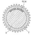
图2是具有一个设计成飞轮的调节电机的调节装置示意图,Fig. 2 is a schematic diagram of an adjusting device with an adjusting motor designed as a flywheel,
图3a是设计成扭簧并布置在链轮和凸轮轴之间的辅助驱动装置示意图,Figure 3a is a schematic diagram of an auxiliary drive designed as a torsion spring and arranged between the sprocket and the camshaft,
图3b是设计成弹簧并在链轮和调节轴之间起作用的辅助装置示意图,Figure 3b is a schematic diagram of an auxiliary device designed as a spring and acting between the sprocket and the adjustment shaft,
图4是具有在调节轴和链轮之间布置气动马达或液压马达的调节装置示意图,Fig. 4 is a schematic diagram of an adjustment device with an air motor or a hydraulic motor arranged between the adjustment shaft and the sprocket,
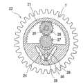
图5a是设计成离心电机并处在基准位置的辅助驱动装置横剖面图,Figure 5a is a cross-sectional view of an auxiliary drive device designed as a centrifugal motor and in a reference position,
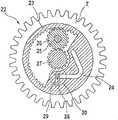
图5b是设计成离心电机但不处在基准位置的辅助驱动装置横剖面图,Figure 5b is a cross-sectional view of the auxiliary drive device designed as a centrifugal motor but not in the reference position,
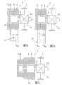
图6a是具有辅助驱动装置和内部布置制动器的调节装置示意图,Figure 6a is a schematic diagram of an adjustment device with an auxiliary drive and an internally arranged brake,
图6b是具有辅助驱动装置和外部布置制动器的调节装置示意图,Figure 6b is a schematic diagram of an adjustment device with an auxiliary drive and an externally arranged brake,
图7a是具有通过电容器供给能量的辅助驱动装置的调节装置示意图,Figure 7a is a schematic diagram of a regulating device with an auxiliary drive supplied with energy via a capacitor,
图7b是具有通过外部电源供给能量的辅助驱动装置的调节装置示意图,Figure 7b is a schematic diagram of a regulating device with an auxiliary drive device supplied with energy from an external power source,
图7c是具有外部的设计成电动机的辅助驱动装置的调节装置示意图,FIG. 7c is a schematic diagram of an adjusting device with an external auxiliary drive designed as an electric motor,
图8具有安全联轴器的调节装置示意图,Figure 8 is a schematic diagram of an adjustment device with a safety coupling,
图9具有锁紧单元的调节装置横剖面图。Figure 9 is a cross-sectional view of the adjustment device with locking unit.
具体实施方式Detailed ways
本发明的实施例在图1中示出为具有变速齿轮箱13和基本上由转子8和定子9组成的调节电机2的调节装置。所述调节装置用于调节在未示出的内燃机中曲轴和凸轮轴3之间的转角位置。所述变速齿轮箱13设计成三轴变速器,具有一个主动件4,一个从动件5和一根调节轴6。主动件4与驱动轮7并通过未示出的齿轮、齿形带或者齿形链与曲轴固定连接。从动件5与凸轮轴3以及调节轴6与调节电机2的转子8固定连接。调节电机2的定子9与气缸盖10固定连接并处于静止状态。凸轮轴3具有一个对于可靠起动和限定运行必须要到达的基准位置或应急运行位置。在调节电机2没有故障期间,由于调节电机2在内燃机停止运行或重新起动期间将凸轮轴3调节到基准位置,因此即使在没有辅助驱动装置11(图2)的内燃机发生熄火后也可以实现。但是在调节电机2发生故障的情况下,如没有辅助驱动装置11,就无法调节转角位置。An embodiment of the invention is shown in FIG. 1 as an adjusting device with a variable-
在图2中示出了设计成飞轮12的辅助驱动装置11,所述辅助驱动装置直接布置在调节轴6上,因而与调节电机2固定连接。为此驱动轮7一方面与调节轴6,另一方面则与凸轮轴3有效连接。飞轮12可以集成在调节装置1中以节省空间,其中特别有利的是,质量块尽可能远离旋转轴布置,以便在规定惯性矩的情况下使用尽可能小的质量。但是如果调节电机2的转子8已经有很大的质量,如果还用作转矩存储器的转子8具有足够高的转矩,则必要时可以不使用附加的飞轮12。FIG. 2 shows an
在图3a中示出了设计成双作用扭簧14的辅助驱动装置11。它在凸轮轴3和驱动轮7之间起作用。基准位置可以通过凸轮轴位置和驱动轮位置之间的转角来形成,其中调节电机2对力矩平衡没有影响。在正常运行下电气的调节电机2改变平衡,从而使扭簧14偏转。如果调节电机2发生了故障,则扭簧14就从偏转的位置松弛到其静止位置。扭簧14本身可以单作用或者双作用。在图3b中弹簧18被布置在驱动轮7和调节轴6之间。在这种情况下力矩通过调节轴6的减速机构15进行传递,否则该功能机构相应于在图3a中示出的;特别是这里可以使用单作用的弹簧18或者螺旋弹簧。FIG. 3 a shows the
在图4中示出了具有设计成气动马达16的辅助驱动装置11的调节装置1。气动马达的外壳20以及其内腔抗扭地与驱动轮7相连接,气动马达转子21抗扭地与调节轴6相连接。一旦调节电机2发生故障,则气动马达16就作为主动的驱动装置或者持续地接受其功能,或者如同在被动的辅助驱动装置中调节装置1只调节到基准位置,然后通过锁紧单元19(图9)将该基准位置保持固定状态。气动马达16可能的结构型式例如有片式马达或齿形马达。FIG. 4 shows the adjusting
除了气动马达16外,辅助驱动装置11也可以设计成液压马达17,其中特别适宜的是使用滚子叶片泵、内齿轮泵或叶轮式泵。In addition to the pneumatic motor 16 , the
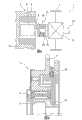
在图5a和5b中示出了基本上由具有滑槽24的内齿轮23组成的离心电机22,所述内齿轮固定在驱动轮7上的方法是,它相对于该驱动轮可以转动。5 a and 5 b show a
内齿轮23在行星轮25上面,所述行星轮布置在与驱动轮7固定连接的连接轴26(Stegwelle)上,并与布置在调节轴6上的中心轮27产生有效传递连接。在滑槽24内有一个具有与其固定连接的质量块30的滑动套28,所述滑动套28同时在一个长形孔29内滑动,其中长形孔集成在驱动轮7上并呈径向。除了滑动套28之外还可以布置滑块。原则上滑槽24可以具有任意的形状,只要它不是精确地沿着径向,并且调节装置的基准位置相应于滑动套的位置和沿径向与内齿轮23的中心距离最远。特别有利的是,滑槽24采用抛物线或V形结构。The
在驱动轮7达到了最低转速之后,离心电机22就处于准备运行的状态。如果调节电机2开始了转角调节,则它通过调节轴6和中心轮27旋转驱动轮7。同时通过联轴器和行星轮25旋转内齿轮23,由此使质量块30通过滑槽沿着径向朝里拉(图5b)。当调节电机2发生故障时,由于离心力的作用质量块30运动到最外面的位置处。能流则反向流动,调节装置1被调节到基准位置。必要时在那里用锁紧单元19(图9)将调节装置1锁紧。After the
在图6a和6b中示出了设计成制动器31的辅助装置11,其中在图5a中涉及一个集成在电气的调节电机内的制动器31。它可以例如设计成短路制动器绕组,这样可以通过感应来制动调节电机2。另外一种可能是一个可以用作应急运行绕组35的独立的绕组。但是制动器31也可以布置在外面(图6b),例如布置在调节轴上的制动盘32,它在失灵的情况下通过液压或电磁动作的制动块33进行制动。制动器31的其它可能的结构型式有带式制动器、盘式制动器或蹄式制动器。制动器31可以直接地对从动件5并从而对凸轮轴3起作用,或者间接地例如对通过联轴器与调节轴相连接的轴起作用。6 a and 6 b show
在图7a和7b中示出了设计成电动机34的辅助驱动装置11,其中其转子通过调节电机2的转子而构成。电动机34的转子设计成一个独立的绕组作为应急运行绕组35。电动机34的供电或者通过电容器36或者通过外部的电网37来确保。除了电容器36以外还可以使用电池。另外一个替换方案是通过皮带或链条来传动。图7c中清楚地示出了电动机34也可作为外部的零件来实现。7 a and 7 b show
在图8中示出了具有一个调节电机2的调节装置1,其中一个安全联轴器38布置在调节电机2和从动轴5之间。如果调节轴6闭锁,则该闭锁对凸轮轴3没有止动影响。较有利的是,辅助驱动装置11布置在安全联轴器38的后面,从而使发生故障的调节电机2不会对辅助驱动装置11产生负面作用。这里安全联轴器38可以根据现有的技术选择熟知的联轴器,例如通过压簧39动作或者电磁作用的联轴器盘40、41。FIG. 8 shows the adjusting
在图9中示范性地示出了锁紧单元19的可能布置方式,为了在失灵的情况下固定转角,所述锁紧单元在前面所述的被动的系统中是必要的。这里锁紧单元19被设计成径向作用的弹簧元件。在本图中解锁和锁紧都是通过油槽42供给的油压来进行。另外一个替换方案是,锁紧单元19的动作可以使用离心力、电磁力或者调节轴的旋转脉冲。锁紧单元19在调节装置中既可以轴向布置,也可以径向布置。FIG. 9 shows an example of a possible arrangement of the locking
总之,通过根据本发明的辅助驱动装置11的设计结构,在调节电机2发生故障的情况下,可以实现受控的或者是主动或者是被动地复位到基准位置,从而使内燃机通过在曲轴和凸轮轴3之间的固定转角仍然能够可靠地工作。In short, through the design structure of the
附图标记reference sign
1 调节装置1 adjustment device
2 调节电机2 Adjust the motor
3 凸轮轴3 camshaft
4 主动件4 active parts
5 从动件5 follower
6 调节轴6 adjustment shaft
7 驱动轴7 drive shaft
8 转子8 rotors
9 定子9 stator
10 气缸盖10 cylinder head
11 辅助驱动装置11 Auxiliary drive device
12 飞轮12 flywheel
13 变速齿轮箱13 speed gearbox
14 扭簧14 torsion spring
15 减速机构15 reduction mechanism
16 气动马达16 air motor
17 液压马达17 hydraulic motor
18 弹簧18 springs
19 锁紧单元19 locking unit
20 外壳20 shells
21 气动马达转子21 Air motor rotor
22 离心电机22 centrifugal motor
23 内齿轮23 internal gear
24 滑槽24 chute
25 行星轮25 planetary gear
26 连接轴26 connecting shaft
27 中心轮27 center wheel
28 滑动套28 sliding sleeve
29 长形孔29 long hole
30 质量块30 mass block
31 制动器31 Brake
32 制动盘32 brake disc
33 制动块33 brake block
34 电动机34 electric motor
35 应急运行绕组35 Emergency running winding
36 电容器36 capacitors
37 外部电网37 External grid
38 安全联轴器38 safety coupling
39 压簧39 compression spring
40 联轴器盘40 Coupling disc
41 联轴器盘41 Coupling disc
42 油槽42 oil tank
Claims (8)
Translated fromChineseApplications Claiming Priority (2)
| Application Number | Priority Date | Filing Date | Title |
|---|---|---|---|
| DE102004033522ADE102004033522A1 (en) | 2004-07-10 | 2004-07-10 | Camshaft adjuster with electric drive |
| DE102004033522.2 | 2004-07-10 |
Publications (2)
| Publication Number | Publication Date |
|---|---|
| CN1985070A CN1985070A (en) | 2007-06-20 |
| CN100529362Ctrue CN100529362C (en) | 2009-08-19 |
Family
ID=34970255
Family Applications (1)
| Application Number | Title | Priority Date | Filing Date |
|---|---|---|---|
| CNB2005800231804AExpired - Fee RelatedCN100529362C (en) | 2004-07-10 | 2005-06-15 | Electrically driven camshaft adjuster |
Country Status (6)
| Country | Link |
|---|---|
| US (1) | US7597075B2 (en) |
| EP (1) | EP1766197B1 (en) |
| JP (1) | JP2008506070A (en) |
| CN (1) | CN100529362C (en) |
| DE (1) | DE102004033522A1 (en) |
| WO (1) | WO2006005406A1 (en) |
Families Citing this family (35)
| Publication number | Priority date | Publication date | Assignee | Title |
|---|---|---|---|---|
| DE102004033894B4 (en)* | 2004-07-14 | 2009-02-12 | Daimler Ag | Camshaft adjustment device |
| DE102004038171A1 (en)* | 2004-08-06 | 2006-03-16 | Daimlerchrysler Ag | Device for adjusting a camshaft and method for operating a device for adjusting a camshaft |
| JPWO2006025173A1 (en)* | 2004-09-01 | 2008-05-08 | 日鍛バルブ株式会社 | Engine phase variable device |
| DE102005023006B4 (en)* | 2005-05-19 | 2019-05-23 | Daimler Ag | Camshaft adjustment device |
| DE102006007584A1 (en)* | 2006-02-18 | 2007-08-30 | Schaeffler Kg | Camshaft adjuster with a superposition gearbox |
| KR20090074161A (en)* | 2006-09-19 | 2009-07-06 | 팀켄 컴퍼니 | Continuous Camshaft Phase Shifter |
| WO2009067789A1 (en)* | 2007-11-26 | 2009-06-04 | Magna Powertrain Inc. | Concentric camshaft with electric phase drive |
| DE102009019397B4 (en) | 2008-07-07 | 2017-11-23 | Schaeffler Technologies AG & Co. KG | Phase adjuster for internal combustion engines with a locking element |
| DE102008039007A1 (en)* | 2008-08-21 | 2010-02-25 | Schaeffler Kg | Method for adjusting a crankshaft of an internal combustion engine, camshaft adjusting system and engine with adjustable crankshaft |
| DE102008050824A1 (en) | 2008-10-08 | 2010-04-15 | Schaeffler Kg | Emergency brake for use in electromechanical adjusting device for camshaft of internal combustion engine, has brake disk or magnet housing moved between free-running and braking positions by magnetic force generated by energizing coil |
| DE102008043671A1 (en) | 2008-11-12 | 2010-05-20 | Zf Friedrichshafen Ag | Adjustment system for camshafts of an internal combustion engine |
| DE102008043673A1 (en) | 2008-11-12 | 2010-05-20 | Zf Friedrichshafen Ag | Camshaft adjustment system for internal combustion engine, has differential drives formed as planet gear with output element comprising hollow wheel |
| DE102009001794A1 (en) | 2009-03-24 | 2010-09-30 | Zf Friedrichshafen Ag | Adjustment system for cam shafts of internal-combustion engine of motor vehicle, has electrical machine consisting of external rotor and stator, and another machine arranged with elements of gear unit in plane perpendicular to axis of shaft |
| US11512922B2 (en) | 2010-01-10 | 2022-11-29 | John Paul Schaffer | Adjustable arrow lift and slide rest |
| DE102010045358A1 (en)* | 2010-04-10 | 2011-10-13 | Hydraulik-Ring Gmbh | Schwenkmotornockenwellenversteller with a hydraulic valve |
| DE102010021774A1 (en)* | 2010-05-27 | 2011-12-01 | Daimler Ag | Adjusting device for an internal combustion engine valve drive device |
| EP2520772B1 (en)* | 2011-05-02 | 2016-06-29 | MAGNA Powertrain GmbH & Co KG | Camshaft adjuster with emergency operation device |
| US8677961B2 (en) | 2011-07-18 | 2014-03-25 | Delphi Technologies, Inc. | Harmonic drive camshaft phaser with lock pin for selectivley preventing a change in phase relationship |
| CN103359921B (en)* | 2012-04-11 | 2016-05-11 | 洛阳建材机械厂 | For the online method and apparatus of changing annealing kiln transmission system |
| DE102013017271A1 (en)* | 2013-10-17 | 2015-04-23 | Daimler Ag | Camshaft adjuster for an internal combustion engine |
| DE102014001396A1 (en)* | 2014-02-04 | 2015-08-06 | Daimler Ag | Camshaft adjusting device |
| CN103953408B (en)* | 2014-04-30 | 2016-08-17 | 桂林电子科技大学 | Electrodeless variable valve timing mechanism |
| DE112015002518B4 (en)* | 2014-06-25 | 2017-11-16 | Borgwarner Inc. | Camshaft adjuster systems and associated adjuster with lock |
| DE102014013691A1 (en)* | 2014-09-17 | 2016-03-17 | Daimler Ag | Camshaft adjusting device for an internal combustion engine of a motor vehicle |
| DE102014014279A1 (en)* | 2014-09-27 | 2016-03-31 | Daimler Ag | Camshaft adjusting device |
| CN105610274B (en)* | 2015-12-22 | 2017-09-19 | 中国科学院长春光学精密机械与物理研究所 | A shaft-through lockable centrifugal mechanism |
| SE540733C2 (en) | 2016-06-15 | 2018-10-23 | Scania Cv Ab | Internal combustion engine and vehicle comprising a hydraulic phase displacement device |
| DE102016219915A1 (en) | 2016-10-13 | 2018-04-19 | Schaeffler Technologies AG & Co. KG | The wave gear |
| DE102016220631A1 (en)* | 2016-10-20 | 2017-08-31 | Schaeffler Technologies AG & Co. KG | adjustment |
| DE102017105736B4 (en)* | 2017-03-17 | 2019-02-14 | Schaeffler Technologies AG & Co. KG | Adjustment device for an internal combustion engine |
| DE102017111222B3 (en) | 2017-05-23 | 2018-08-30 | Schaeffler Technologies AG & Co. KG | Phaser |
| JP7161917B2 (en)* | 2018-10-31 | 2022-10-27 | 株式会社ミクニ | Phase change unit and valve timing change device |
| US11280228B2 (en)* | 2020-07-07 | 2022-03-22 | Borgwarner, Inc. | Variable camshaft timing assembly |
| DE102020120618A1 (en) | 2020-08-05 | 2022-02-10 | Schaeffler Technologies AG & Co. KG | Arrangement for adjusting a camshaft for variable valve control of an internal combustion engine and method for operating an arrangement for adjusting a camshaft |
| DE102021105281A1 (en) | 2021-03-04 | 2022-09-08 | Schaeffler Technologies AG & Co. KG | Electromechanical camshaft phaser and method for operating a camshaft phaser |
Family Cites Families (20)
| Publication number | Priority date | Publication date | Assignee | Title |
|---|---|---|---|---|
| DE4110195C2 (en) | 1991-03-28 | 2000-02-10 | Schaeffler Waelzlager Ohg | Adjustment device for a camshaft |
| JPH0533615A (en)* | 1991-07-26 | 1993-02-09 | Toyota Motor Corp | Variable valve timing device |
| DE19541770A1 (en) | 1995-11-09 | 1997-06-12 | Schaeffler Waelzlager Kg | Device for changing the opening and closing times of gas exchange valves of an internal combustion engine |
| US5680837A (en) | 1996-09-17 | 1997-10-28 | General Motors Corporation | Planetary cam phaser with worm electric actuator |
| JPH10103029A (en)* | 1996-09-26 | 1998-04-21 | Asmo Co Ltd | Variable valve timing controller for internal combustion engine |
| JP3917772B2 (en)* | 1999-02-04 | 2007-05-23 | 株式会社日立製作所 | Variable valve operating device for internal combustion engine |
| AT409786B (en) | 1999-03-23 | 2002-11-25 | Tcg Unitech Ag | Arrangement for displacing an internal combustion engine camshaft has electric motor housing mounting elements fed into drive wheel via apertures that limit camshaft adjustment range |
| US6328006B1 (en)* | 1999-03-23 | 2001-12-11 | Tcg Unitech Aktiengesellschaft | Device for adjusting the phase angle of a camshaft of an internal combustion engine |
| JP4406989B2 (en) | 2000-02-22 | 2010-02-03 | トヨタ自動車株式会社 | Valve characteristic control device for internal combustion engine |
| US6591799B1 (en)* | 2000-07-10 | 2003-07-15 | Mitsubishi Denki Kabushiki Kaisha | Valve timing adjusting device |
| JP2002227623A (en)* | 2001-01-31 | 2002-08-14 | Unisia Jecs Corp | Valve timing control device for internal combustion engine |
| JP2002256921A (en)* | 2001-02-28 | 2002-09-11 | Toyota Motor Corp | Vehicle control device |
| DE10207760B4 (en) | 2002-02-23 | 2019-10-31 | Schaeffler Technologies AG & Co. KG | Device for releasably connecting and adjusting two mutually drehwinkelverstellbarer waves |
| DE10220687A1 (en)* | 2002-05-10 | 2003-11-20 | Ina Schaeffler Kg | Camshaft adjuster with electric drive |
| DE10257706A1 (en) | 2002-07-11 | 2004-01-29 | Ina-Schaeffler Kg | Electrically-driven camshaft adjuster for IC engine allows adjustment of camshaft into basic advanced or retarded position by braking of adjustment shaft when setting drive rotates |
| DE10248355A1 (en) | 2002-10-17 | 2004-04-29 | Ina-Schaeffler Kg | Camshaft adjuster with electric drive |
| JP3865702B2 (en) | 2003-03-06 | 2007-01-10 | 株式会社デンソー | Engine protection device for vehicles equipped with variable valve timing device |
| DE10326886A1 (en) | 2003-06-14 | 2004-12-30 | Daimlerchrysler Ag | Camshaft positioner for an internal combustion engine |
| DE10332264A1 (en) | 2003-07-16 | 2005-02-03 | Aft Atlas Fahrzeugtechnik Gmbh | Electromechanical phaser and method of operation |
| DE10352361B4 (en) | 2003-11-10 | 2020-08-27 | Schaeffler Technologies AG & Co. KG | Camshaft adjuster with electric drive |
- 2004
- 2004-07-10DEDE102004033522Apatent/DE102004033522A1/ennot_activeCeased
- 2005
- 2005-06-15WOPCT/EP2005/006387patent/WO2006005406A1/ennot_activeApplication Discontinuation
- 2005-06-15CNCNB2005800231804Apatent/CN100529362C/ennot_activeExpired - Fee Related
- 2005-06-15USUS11/571,861patent/US7597075B2/ennot_activeExpired - Fee Related
- 2005-06-15JPJP2007520683Apatent/JP2008506070A/enactivePending
- 2005-06-15EPEP05750465.6Apatent/EP1766197B1/ennot_activeExpired - Lifetime
Also Published As
| Publication number | Publication date |
|---|---|
| JP2008506070A (en) | 2008-02-28 |
| US7597075B2 (en) | 2009-10-06 |
| DE102004033522A1 (en) | 2006-02-09 |
| US20080053389A1 (en) | 2008-03-06 |
| EP1766197A1 (en) | 2007-03-28 |
| WO2006005406A1 (en) | 2006-01-19 |
| EP1766197B1 (en) | 2013-08-14 |
| CN1985070A (en) | 2007-06-20 |
Similar Documents
| Publication | Publication Date | Title |
|---|---|---|
| CN100529362C (en) | Electrically driven camshaft adjuster | |
| JP4233521B2 (en) | Cam shaft adjusting device with electric drive | |
| US7421990B2 (en) | Harmonic drive camshaft phaser | |
| US8677963B2 (en) | Electrical camshaft phaser with energy recovery | |
| JP4600379B2 (en) | Valve timing adjustment device | |
| US7578273B2 (en) | Device for adjusting the phase angle between two rotating, drive-connected element | |
| JP4518149B2 (en) | Valve timing adjustment device | |
| US8651076B2 (en) | Adjusting system for camshafts of an internal combustion engine | |
| US7475661B2 (en) | Camshaft phaser having a differential bevel gear system | |
| US8141527B2 (en) | Camshaft adjuster having a variable ratio gear unit | |
| JP2005532503A (en) | Cam shaft adjusting device with electric drive | |
| JP2010151088A (en) | Variable compression ratio device for internal combustion engine | |
| JP4370244B2 (en) | Device for adjusting the relative angle between two rotating elements | |
| JPH11107718A (en) | Rotational phase control device | |
| US8813703B2 (en) | Method for adjusting a crankshaft of an internal combustion engine, camshaft adjustment system, and internal combustion engine having an adjustable crankshaft | |
| US20050103299A1 (en) | Electrically driven camshaft | |
| JP2011526340A (en) | Camshaft unit | |
| JP4875068B2 (en) | Cam shaft adjustment device | |
| US7824271B2 (en) | Device for adjusting the relative angular position of two rotating elements | |
| KR101193358B1 (en) | Electrically Driven Camshaft Adjuster | |
| JP7466428B2 (en) | Limit setting device | |
| JP2008025408A (en) | Valve timing adjustment device | |
| US20050115529A1 (en) | Device for adjusting the relative angular position of two rotating elements |
Legal Events
| Date | Code | Title | Description |
|---|---|---|---|
| C06 | Publication | ||
| PB01 | Publication | ||
| C10 | Entry into substantive examination | ||
| SE01 | Entry into force of request for substantive examination | ||
| C14 | Grant of patent or utility model | ||
| GR01 | Patent grant | ||
| ASS | Succession or assignment of patent right | Owner name:SCHAEFFLER KG Free format text:FORMER OWNER: FAG KUGELFISCHER AG + CO. OHG Effective date:20100909 | |
| C41 | Transfer of patent application or patent right or utility model | ||
| TR01 | Transfer of patent right | Effective date of registration:20100909 Address after:German Herzogenaurach Patentee after:SCHAEFFLER TECHNOLOGIES GmbH & Co.KG Address before:German Herzogenaurach Patentee before:SCHAEFFLER KG | |
| C56 | Change in the name or address of the patentee | ||
| CP01 | Change in the name or title of a patent holder | Address after:German Herzogenaurach Patentee after:SCHAEFFLER TECHNOLOGIES AG & CO. KG Address before:German Herzogenaurach Patentee before:SCHAEFFLER TECHNOLOGIES GmbH & Co.KG | |
| ASS | Succession or assignment of patent right | Owner name:SCHAEFFLER FIFTH INVESTMENT MANAGEMENT GMBH + CO., Free format text:FORMER OWNER: SCHAEFFLER TECHNOLOGIES GMBH + CO. KG Effective date:20150805 | |
| C41 | Transfer of patent application or patent right or utility model | ||
| C56 | Change in the name or address of the patentee | Owner name:SCHAEFFLER TECHNOLOGIES GMBH + CO. KG Free format text:FORMER NAME: SCHAEFFLER FIFTH INVESTMENT MANAGEMENT GMBH + CO., KG Owner name:SCHAEFFLER TECHNOLOGY GMBH + CO. KG Free format text:FORMER NAME: SCHAEFFLER TECHNOLOGIES GMBH + CO. KG | |
| CP01 | Change in the name or title of a patent holder | Address after:German Herzogenaurach Patentee after:SCHAEFFLER TECHNOLOGIES GmbH & Co.KG Address before:German Herzogenaurach Patentee before:Fifth Schaeffler investment management GmbH & Co.KG Address after:German Herzogenaurach Patentee after:SCHAEFFLER TECHNOLOGIES AG & CO.KG Address before:German Herzogenaurach Patentee before:SCHAEFFLER TECHNOLOGIES GmbH & Co.KG | |
| TR01 | Transfer of patent right | Effective date of registration:20150805 Address after:German Herzogenaurach Patentee after:Fifth Schaeffler investment management GmbH & Co.KG Address before:German Herzogenaurach Patentee before:SCHAEFFLER TECHNOLOGIES AG & CO. KG | |
| CF01 | Termination of patent right due to non-payment of annual fee | Granted publication date:20090819 Termination date:20190615 | |
| CF01 | Termination of patent right due to non-payment of annual fee |