CN100526453C - Cell collection method after laser microdissection - Google Patents
Cell collection method after laser microdissectionDownload PDFInfo
- Publication number
- CN100526453C CN100526453CCN200510034838.3ACN200510034838ACN100526453CCN 100526453 CCN100526453 CCN 100526453CCN 200510034838 ACN200510034838 ACN 200510034838ACN 100526453 CCN100526453 CCN 100526453C
- Authority
- CN
- China
- Prior art keywords
- film
- slide
- laser
- laser microdissection
- cells
- Prior art date
- Legal status (The legal status is an assumption and is not a legal conclusion. Google has not performed a legal analysis and makes no representation as to the accuracy of the status listed.)
- Expired - Lifetime
Links
Images


Classifications
- G—PHYSICS
- G01—MEASURING; TESTING
- G01N—INVESTIGATING OR ANALYSING MATERIALS BY DETERMINING THEIR CHEMICAL OR PHYSICAL PROPERTIES
- G01N1/00—Sampling; Preparing specimens for investigation
- G01N1/28—Preparing specimens for investigation including physical details of (bio-)chemical methods covered elsewhere, e.g. G01N33/50, C12Q
- G01N1/2813—Producing thin layers of samples on a substrate, e.g. smearing, spinning-on
- G—PHYSICS
- G01—MEASURING; TESTING
- G01N—INVESTIGATING OR ANALYSING MATERIALS BY DETERMINING THEIR CHEMICAL OR PHYSICAL PROPERTIES
- G01N1/00—Sampling; Preparing specimens for investigation
- G01N1/02—Devices for withdrawing samples
- G01N1/04—Devices for withdrawing samples in the solid state, e.g. by cutting
- C—CHEMISTRY; METALLURGY
- C12—BIOCHEMISTRY; BEER; SPIRITS; WINE; VINEGAR; MICROBIOLOGY; ENZYMOLOGY; MUTATION OR GENETIC ENGINEERING
- C12M—APPARATUS FOR ENZYMOLOGY OR MICROBIOLOGY; APPARATUS FOR CULTURING MICROORGANISMS FOR PRODUCING BIOMASS, FOR GROWING CELLS OR FOR OBTAINING FERMENTATION OR METABOLIC PRODUCTS, i.e. BIOREACTORS OR FERMENTERS
- C12M1/00—Apparatus for enzymology or microbiology
- C—CHEMISTRY; METALLURGY
- C12—BIOCHEMISTRY; BEER; SPIRITS; WINE; VINEGAR; MICROBIOLOGY; ENZYMOLOGY; MUTATION OR GENETIC ENGINEERING
- C12M—APPARATUS FOR ENZYMOLOGY OR MICROBIOLOGY; APPARATUS FOR CULTURING MICROORGANISMS FOR PRODUCING BIOMASS, FOR GROWING CELLS OR FOR OBTAINING FERMENTATION OR METABOLIC PRODUCTS, i.e. BIOREACTORS OR FERMENTERS
- C12M47/00—Means for after-treatment of the produced biomass or of the fermentation or metabolic products, e.g. storage of biomass
- C12M47/04—Cell isolation or sorting
- C—CHEMISTRY; METALLURGY
- C12—BIOCHEMISTRY; BEER; SPIRITS; WINE; VINEGAR; MICROBIOLOGY; ENZYMOLOGY; MUTATION OR GENETIC ENGINEERING
- C12N—MICROORGANISMS OR ENZYMES; COMPOSITIONS THEREOF; PROPAGATING, PRESERVING, OR MAINTAINING MICROORGANISMS; MUTATION OR GENETIC ENGINEERING; CULTURE MEDIA
- C12N1/00—Microorganisms, e.g. protozoa; Compositions thereof; Processes of propagating, maintaining or preserving microorganisms or compositions thereof; Processes of preparing or isolating a composition containing a microorganism; Culture media therefor
- C—CHEMISTRY; METALLURGY
- C12—BIOCHEMISTRY; BEER; SPIRITS; WINE; VINEGAR; MICROBIOLOGY; ENZYMOLOGY; MUTATION OR GENETIC ENGINEERING
- C12Q—MEASURING OR TESTING PROCESSES INVOLVING ENZYMES, NUCLEIC ACIDS OR MICROORGANISMS; COMPOSITIONS OR TEST PAPERS THEREFOR; PROCESSES OF PREPARING SUCH COMPOSITIONS; CONDITION-RESPONSIVE CONTROL IN MICROBIOLOGICAL OR ENZYMOLOGICAL PROCESSES
- C12Q1/00—Measuring or testing processes involving enzymes, nucleic acids or microorganisms; Compositions therefor; Processes of preparing such compositions
- C12Q1/68—Measuring or testing processes involving enzymes, nucleic acids or microorganisms; Compositions therefor; Processes of preparing such compositions involving nucleic acids
- C12Q1/6806—Preparing nucleic acids for analysis, e.g. for polymerase chain reaction [PCR] assay
- G—PHYSICS
- G01—MEASURING; TESTING
- G01N—INVESTIGATING OR ANALYSING MATERIALS BY DETERMINING THEIR CHEMICAL OR PHYSICAL PROPERTIES
- G01N1/00—Sampling; Preparing specimens for investigation
- G01N1/28—Preparing specimens for investigation including physical details of (bio-)chemical methods covered elsewhere, e.g. G01N33/50, C12Q
- G01N1/286—Preparing specimens for investigation including physical details of (bio-)chemical methods covered elsewhere, e.g. G01N33/50, C12Q involving mechanical work, e.g. chopping, disintegrating, compacting, homogenising
- G—PHYSICS
- G01—MEASURING; TESTING
- G01N—INVESTIGATING OR ANALYSING MATERIALS BY DETERMINING THEIR CHEMICAL OR PHYSICAL PROPERTIES
- G01N1/00—Sampling; Preparing specimens for investigation
- G01N1/28—Preparing specimens for investigation including physical details of (bio-)chemical methods covered elsewhere, e.g. G01N33/50, C12Q
- G01N1/30—Staining; Impregnating ; Fixation; Dehydration; Multistep processes for preparing samples of tissue, cell or nucleic acid material and the like for analysis
- G—PHYSICS
- G02—OPTICS
- G02B—OPTICAL ELEMENTS, SYSTEMS OR APPARATUS
- G02B21/00—Microscopes
- G02B21/32—Micromanipulators structurally combined with microscopes
- G—PHYSICS
- G02—OPTICS
- G02B—OPTICAL ELEMENTS, SYSTEMS OR APPARATUS
- G02B21/00—Microscopes
- G02B21/34—Microscope slides, e.g. mounting specimens on microscope slides
- G—PHYSICS
- G01—MEASURING; TESTING
- G01N—INVESTIGATING OR ANALYSING MATERIALS BY DETERMINING THEIR CHEMICAL OR PHYSICAL PROPERTIES
- G01N1/00—Sampling; Preparing specimens for investigation
- G01N1/28—Preparing specimens for investigation including physical details of (bio-)chemical methods covered elsewhere, e.g. G01N33/50, C12Q
- G01N1/40—Concentrating samples
- G01N1/4077—Concentrating samples by other techniques involving separation of suspended solids
- G—PHYSICS
- G01—MEASURING; TESTING
- G01N—INVESTIGATING OR ANALYSING MATERIALS BY DETERMINING THEIR CHEMICAL OR PHYSICAL PROPERTIES
- G01N1/00—Sampling; Preparing specimens for investigation
- G01N1/28—Preparing specimens for investigation including physical details of (bio-)chemical methods covered elsewhere, e.g. G01N33/50, C12Q
- G01N1/2813—Producing thin layers of samples on a substrate, e.g. smearing, spinning-on
- G01N2001/2833—Collecting samples on a sticky, tacky, adhesive surface
- G01N2001/284—Collecting samples on a sticky, tacky, adhesive surface using local activation of adhesive, i.e. Laser Capture Microdissection
- Y—GENERAL TAGGING OF NEW TECHNOLOGICAL DEVELOPMENTS; GENERAL TAGGING OF CROSS-SECTIONAL TECHNOLOGIES SPANNING OVER SEVERAL SECTIONS OF THE IPC; TECHNICAL SUBJECTS COVERED BY FORMER USPC CROSS-REFERENCE ART COLLECTIONS [XRACs] AND DIGESTS
- Y10—TECHNICAL SUBJECTS COVERED BY FORMER USPC
- Y10T—TECHNICAL SUBJECTS COVERED BY FORMER US CLASSIFICATION
- Y10T436/00—Chemistry: analytical and immunological testing
- Y10T436/25—Chemistry: analytical and immunological testing including sample preparation
- Y10T436/25375—Liberation or purification of sample or separation of material from a sample [e.g., filtering, centrifuging, etc.]
Landscapes
- Chemical & Material Sciences (AREA)
- Life Sciences & Earth Sciences (AREA)
- Health & Medical Sciences (AREA)
- Physics & Mathematics (AREA)
- Engineering & Computer Science (AREA)
- Analytical Chemistry (AREA)
- Organic Chemistry (AREA)
- Biochemistry (AREA)
- General Health & Medical Sciences (AREA)
- General Physics & Mathematics (AREA)
- Zoology (AREA)
- Wood Science & Technology (AREA)
- Bioinformatics & Cheminformatics (AREA)
- Biotechnology (AREA)
- Immunology (AREA)
- Genetics & Genomics (AREA)
- Pathology (AREA)
- Microbiology (AREA)
- General Engineering & Computer Science (AREA)
- Optics & Photonics (AREA)
- Biomedical Technology (AREA)
- Molecular Biology (AREA)
- Proteomics, Peptides & Aminoacids (AREA)
- Sustainable Development (AREA)
- Medicinal Chemistry (AREA)
- Biophysics (AREA)
- Cell Biology (AREA)
- Tropical Medicine & Parasitology (AREA)
- Virology (AREA)
- Chemical Kinetics & Catalysis (AREA)
- Sampling And Sample Adjustment (AREA)
- Investigating Or Analysing Biological Materials (AREA)
- Apparatus Associated With Microorganisms And Enzymes (AREA)
Abstract
Translated fromChinese
Description
Translated fromChinese技术领域technical field
本发明涉及一种激光显微切割后细胞收集方法。The invention relates to a method for collecting cells after laser microdissection.
背景技术Background technique
在生命科学研究领域,需要对组织中某一特定的细胞群体进行基因和蛋白质的研究,可从多样性的组织中分离出形态单一的细胞群体,从而避免实验标本中其他细胞群的污染,使基因和蛋白的分析更加准确特异。较早出现的显微切割技术是用手工或在显微操作仪器的引导下,采用玻璃微针或其他工具对所需要的细胞群体进行机械分离,但该方法操作难度较大,效率较低,精确度较差,对实验者的实验技能要求较高,同时经过机械分离的生物样品被分离后生物活性较低。1996年,开始出现用激光束作为切割手段对所需要的细胞群体进行精细分离。从此,激光显微切割仪器作为一种新型有效的分离切割工具在生物医学领域得到迅速运用和推广。In the field of life science research, it is necessary to conduct gene and protein research on a specific cell population in the tissue, and a single cell population can be isolated from diverse tissues, thereby avoiding the contamination of other cell populations in the experimental specimen, making The analysis of genes and proteins is more accurate and specific. The microdissection technique that appeared earlier is to mechanically separate the required cell populations by using glass microneedles or other tools under the guidance of a micromanipulator, but this method is difficult to operate and low in efficiency. The accuracy is poor, and the experimental skills of the experimenter are required to be high. At the same time, the biological activity of the mechanically separated biological samples is low after being separated. In 1996, the laser beam was used as a cutting method to finely separate the desired cell population. Since then, laser microdissection instrument has been rapidly used and promoted as a new type of effective separation and cutting tool in the field of biomedicine.
成熟的激光显微切割仪器应具有切割效果好,收集效率高和对后续基因蛋白检测影响小的特征。其中,不同的收集技术是各种激光显微切割系统的核心技术。到目前为止,基于激光显微切割发展起来的细胞分离技术可分为激光捕获显微切割技术(LCM),激光弹射技术(LPC),膜粘黏技术和激光切割后重力收集技术。激光捕获切割技术是采用激光束作用热融塑料薄膜,薄膜受热后体积膨胀,包绕所分离的组织周围并和该组织粘黏,薄膜分离时,将与其粘黏的目标组织从组织切片上分离。该方法的主要缺点是利用热融塑料薄膜粘黏力将组织机械地分离,对组织有一定的损伤;同时精确度较低,会将分离组织周围的非目标组织一同分离。激光弹射技术采用激光束直接切割目标组织,利用激光束产生的冲力将切割后的组织克服重力向上方弹射入收集管中。该方法的主要缺点是激光束的弹射作用对生物组织活性有一定程度的损伤。膜粘黏技术是激光将组织切割后,用某种特制的材料将组织切片上的切割组织进行粘黏而分离。该方法所用的特制材料制成的收集管造价较高。激光切割后重力收集技术是采用正置显微镜下切割,切割后的组织因重力作用自动降落到正下方的收集管中。该方法因采用正置显微镜而在应用方面有一定的限制,如无法对培养的活细胞进行显微切割。A mature laser microdissection instrument should have the characteristics of good cutting effect, high collection efficiency and little impact on subsequent gene protein detection. Among them, different collection techniques are the core technology of various laser microdissection systems. So far, the cell separation technology developed based on laser microdissection can be divided into laser capture microdissection (LCM), laser ejection technology (LPC), membrane adhesion technology and gravity collection technology after laser cutting. Laser capture cutting technology uses laser beams to heat melt plastic films. The volume of the film expands after heating, wrapping around the separated tissue and sticking to the tissue. When the film is separated, the target tissue sticking to it is separated from the tissue slice. . The main disadvantage of this method is that the tissue is mechanically separated by the adhesive force of the hot-melt plastic film, which will cause some damage to the tissue; at the same time, the accuracy is low, and the non-target tissue around the separated tissue will be separated together. Laser ejection technology uses a laser beam to directly cut the target tissue, and uses the impulse generated by the laser beam to eject the cut tissue upward against gravity into the collection tube. The main disadvantage of this method is that the ejection of the laser beam will damage the activity of biological tissues to a certain extent. Membrane adhesion technology is to use a special material to stick and separate the cut tissue on the tissue slice after the tissue is cut by laser. The collection tube made of the special material used in this method is relatively expensive. The gravity collection technology after laser cutting is to cut under an upright microscope, and the cut tissue will automatically fall into the collection tube directly below due to the action of gravity. Due to the use of an upright microscope, this method has certain limitations in application, such as the inability to microdissect cultured living cells.
发明内容Contents of the invention
本发明的目的在于提供一种激光显微切割后细胞收集方法,其操作方便简单,并可为后续分析提供均一的细胞标本。The purpose of the present invention is to provide a method for collecting cells after laser microdissection, which is convenient and simple to operate, and can provide uniform cell samples for subsequent analysis.
本发明的解决方案是:先将带电荷的薄膜平铺在显微镜载玻片上;再将待分离的组织切片放置在载玻片的薄膜上;并将带与薄膜异性电荷的收集材料放置在组织切片的前方;然后,利用激光显微切割系统产生的激光束切割待分离的细胞和其附着的薄膜;最后,切割下带有细胞的薄膜受载玻片上带同种电荷的薄膜排斥而远离载玻片的薄膜侧,并受带异种电荷的收集材料吸引而吸附至收集材料上,完成收集过程。The solution of the present invention is: first flatly spread the charged film on the microscope slide; then place the tissue section to be separated on the film of the slide; The front of the section; then, the laser beam generated by the laser microdissection system is used to cut the cells to be separated and the attached film; finally, the cut film with cells is repelled by the film with the same charge on the glass slide and away from the slide. The film side of the slide is attracted to the collection material by the heterogeneously charged collection material, completing the collection process.
其中:为了更好地固定薄膜,可将上述薄膜用粘连剂平铺在显微镜载玻片上,粘连剂可选用为紫外线固化胶。Wherein: in order to better fix the film, the film can be spread on the microscope slide with an adhesive, and the adhesive can be selected as ultraviolet curing glue.
上述薄膜选用带负电荷的聚酰亚胺薄膜,收集材料选用带正电荷的琼脂糖凝胶。The above-mentioned films are made of negatively charged polyimide films, and the collection material is made of positively charged agarose gel.
上述聚酰亚胺薄膜厚度控制在4um±0.1um,能很好地穿透激光能量,而不影响激光切割效果。The thickness of the above polyimide film is controlled at 4um±0.1um, which can penetrate laser energy well without affecting the laser cutting effect.
上述琼脂糖收集材料为1.0-1.5%琼脂糖的磷酸缓冲盐溶液在室温下放置形成的凝胶。The agarose collection material is a gel formed by placing 1.0-1.5% agarose in phosphate buffered saline solution at room temperature.
采用上述方法后,本发明借助薄膜使组织切片与载玻片不直接接触,切割后的组织容易与载玻片分离,且薄膜带电荷,被切割下的带有目标组织的薄膜被静电排斥,而收集材料携带异性电荷,与带荷的薄膜配套使用,利用静电吸附原理,恰可收集切割后的带有细胞的薄膜,操作方便简单;薄膜的存在对切割前组织切片的制备和切割后DNA、RNA和蛋白质生物学检测无不良影响,且收集材料对切割细胞后进行的DNA、RNA和蛋白质研究无不良影响,由此,利用该技术能够准确和有效地从组织中筛选和分离出所需要的细胞,为后续的DNA、RNA和蛋白质等分子生物学研究分析提供均一的细胞标本。After adopting the above method, the present invention makes the tissue section and the slide glass not directly contact by means of the film, the cut tissue is easily separated from the slide glass, and the film is charged, and the cut film with the target tissue is electrostatically repelled, The collection material carries opposite charges and is used in conjunction with a charged film. Using the principle of electrostatic adsorption, the cut film with cells can be collected, and the operation is convenient and simple; the existence of the film has great influence on the preparation of tissue slices before cutting and DNA after cutting , RNA and protein biological detection have no adverse effects, and the collected materials have no adverse effects on the research of DNA, RNA and protein after cutting cells, thus, using this technology can accurately and effectively screen and isolate the required cells from tissues Cells, providing uniform cell samples for subsequent molecular biology research and analysis such as DNA, RNA and protein.
附图说明Description of drawings
图1为本发明所采用的激光显微切割系统外观图;Fig. 1 is the appearance diagram of the laser microdissection system adopted in the present invention;
图2A显示薄膜借紫外固化胶粘连在显微镜载玻片上,组织切片放置在薄膜载玻片上;Figure 2A shows that the film is adhered to the microscope slide by UV-curable glue, and the tissue section is placed on the film slide;
图2B显示盛有带正电荷琼脂糖凝胶的离心管管盖倒扣在组织切片的正上方;Figure 2B shows that the cap of the centrifuge tube containing the positively charged agarose gel is upside down directly above the tissue section;
图2C显示激光束切割后的组织和薄膜被正上方的琼脂糖凝胶吸附;Figure 2C shows that the tissue and film cut by the laser beam are absorbed by the agarose gel directly above;
图2D显示离心管管盖与相应的离心管管体扣紧,晃动管内液体,切割后的组织进入液体中;Figure 2D shows that the cap of the centrifuge tube is fastened to the corresponding centrifuge tube body, the liquid in the tube is shaken, and the cut tissue enters the liquid;
图3A为带薄膜的载玻片外观图;Fig. 3 A is the appearance diagram of the glass slide with film;
图3B为组织切片放置在带薄膜的载玻片之薄膜侧的外观图;Figure 3B is an appearance view of a tissue section placed on the film side of a glass slide with film;
图4A显示在离心管盖中的琼脂糖凝胶材料外观图;Figure 4A shows the appearance of the agarose gel material in the cap of the centrifuge tube;
图4B显示装有琼脂糖凝胶的离心管管盖放置在收集支架上的外观图;Figure 4B shows the appearance of the cap of the centrifuge tube with agarose gel placed on the collection rack;
图5A显示第一次切割后,第二次切割前的镜下图;Figure 5A shows the microscopic view after the first cut and before the second cut;
图5B显示第二次切割过程中;(20X)Figure 5B shows the second cutting process; (20X)
图5C显示第二次切割后细胞因静电排斥从薄膜载玻片上飞起。(20X)Figure 5C shows that cells fly off the film slide after the second cut due to electrostatic repulsion. (20X)
图5D显示吸附在琼脂糖凝胶表面的切割后细胞。(20X)Figure 5D shows cleaved cells adsorbed to the surface of the agarose gel. (20X)
具体实施方式Detailed ways
如图1所示,本发明所使用的激光显微切割系统主要包括倒置显微镜1、激光发生器2、机动载物台3、三轴控制杆4、中央控制器5和电脑6组成。As shown in FIG. 1 , the laser microdissection system used in the present invention mainly includes an inverted microscope 1 , a laser generator 2 , a motorized stage 3 , a three-axis control rod 4 , a central controller 5 and a computer 6 .
本发明具体实施过程是:The concrete implementation process of the present invention is:
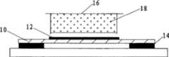
第一步,配合图3A所示,采用带负电荷的聚酰亚胺薄膜10(薄膜也可以选用其它可与后述收集材料带异性电荷而配套使用的材料),聚酰亚胺薄膜10厚度控制在4um±0.1um,能很好地穿透激光能量,而不影响激光切割效果。该薄膜10裁剪成比显微镜载玻片8(经无水乙醇处理过的洁净和干燥的载玻片)略小的矩形形状,如图2A所示,该薄膜10的四周用紫外线固化胶14粘黏在载玻片8上(紫外固化胶为一种经紫外光线照射后转变成粘连剂,并对组织或细胞的基因和蛋白分析没有影响的医用胶),薄膜10中央和载玻片8接触的部分未用固化胶14粘连(这样做是为了使切割后的组织薄膜能够从载玻片8上顺利分离开;如果薄膜10中央也用固化胶14和载玻片8粘连,则即使激光将组织薄膜切割开,组织薄膜复合体因被粘连也无法被静电排斥,即不能被分离回收),该带有薄膜10的载玻片8(如图3A)制成后在紫外灯照射15秒种后,放置在干净环境中待用。The first step, cooperate as shown in Fig. 3A, adopt the
第二步,如图2A、3B所示,将制备的组织切片12(石蜡切片和冰冻切片)直接放置在第一步制成的载玻片8上薄膜10的中央,进行常规的组织切片处理,直至染色。In the second step, as shown in Figures 2A and 3B, the prepared tissue section 12 (paraffin section and frozen section) is directly placed on the center of the
第三步,将第二步制成的组织薄膜切片放置在倒置显微镜1的载物台3上,激光束透过下方的物镜,穿过载玻片8,可以对薄膜10和组织进行切割。In the third step, the tissue thin film section made in the second step is placed on the stage 3 of the inverted microscope 1 , and the laser beam passes through the objective lens below and passes through the
第四步,如图2B所示,在切割组织切处12的正上方放置带正电荷的琼脂糖凝胶材料18(收集材料也可以选用其它可与前述薄膜带异性电荷而配套使用的材料),琼脂糖凝胶材料18存在于离心管管盖16中(如图4A所示),离心管管盖16放置在收集支架7上(如图4B所示),收集支架7可手工操作或机械操作。琼脂糖凝胶材料18不与薄膜8和组织切片12直接接触,相隔几百微米的距离。琼脂糖凝胶材料18的制备为1.0%琼脂糖的磷酸缓冲盐溶液滴加在离心管管盖16中凝固形成的固体凝胶,琼脂糖凝胶材料18的浓度以可形成固体凝胶为准,凝胶高度略低于离心管管盖16的边缘,制备好后,用保鲜膜包裹,放置于4℃冰箱中过夜并保存。In the fourth step, as shown in Figure 2B, a positively charged
第五步,利用激光显微切割系统产生的激光束切割待分离的细胞20和其附着的薄膜10,配合图5A、5B。切割后的细胞20和薄膜10被带同样负电荷的薄膜10排斥(如图5C所示),并被正上方的带正电荷的琼脂糖凝胶材料18吸引,最终被吸附到琼脂糖凝胶材料18表面而回收到离心管管盖16中(如图2C、5D所示)。In the fifth step, the laser beam generated by the laser microdissection system is used to cut the
第六步,观察离心管管盖16表面粘连的切割后细胞20,观察收集效果,达到所要求的细胞20数目时,可终止切割。相同类型的细胞20可收集在同一个离心管管盖16中,不同类型细胞20可收集到不同离心管管盖16中。The sixth step is to observe the
第七步,从收集支架7上小心的取出离心管管盖16,与相对应的离心管管体24扣紧,如图2D所示,晃动离心管管体24中预先加入的液体22,粘连在离心管管盖16琼脂糖凝胶材料18表面的细胞20就进入到液体22中,等待后续的生物学检测。In the seventh step, carefully take out the centrifuge tube cover 16 from the collection bracket 7, and fasten it with the corresponding centrifuge tube body 24, as shown in Figure 2D, shake the pre-added liquid 22 in the centrifuge tube body 24 to prevent adhesion The
Claims (4)
Translated fromChinesePriority Applications (5)
| Application Number | Priority Date | Filing Date | Title |
|---|---|---|---|
| CN200510034838.3ACN100526453C (en) | 2005-05-20 | 2005-05-20 | Cell collection method after laser microdissection |
| DE112006001276.2TDE112006001276B4 (en) | 2005-05-20 | 2006-05-19 | Method and system for collecting cells following laser microdissection |
| US11/914,151US8664002B2 (en) | 2005-05-20 | 2006-05-19 | Method and system for collecting cells following laser microdissection |
| PCT/CA2006/000838WO2006122434A1 (en) | 2005-05-20 | 2006-05-19 | Method and system for collecting cells following laser microdissection |
| GB0722665AGB2440701B8 (en) | 2005-05-20 | 2006-05-19 | Method and system for collecting cells following laser microdissection. |
Applications Claiming Priority (1)
| Application Number | Priority Date | Filing Date | Title |
|---|---|---|---|
| CN200510034838.3ACN100526453C (en) | 2005-05-20 | 2005-05-20 | Cell collection method after laser microdissection |
Publications (2)
| Publication Number | Publication Date |
|---|---|
| CN1865432A CN1865432A (en) | 2006-11-22 |
| CN100526453Ctrue CN100526453C (en) | 2009-08-12 |
Family
ID=37424579
Family Applications (1)
| Application Number | Title | Priority Date | Filing Date |
|---|---|---|---|
| CN200510034838.3AExpired - LifetimeCN100526453C (en) | 2005-05-20 | 2005-05-20 | Cell collection method after laser microdissection |
Country Status (5)
| Country | Link |
|---|---|
| US (1) | US8664002B2 (en) |
| CN (1) | CN100526453C (en) |
| DE (1) | DE112006001276B4 (en) |
| GB (1) | GB2440701B8 (en) |
| WO (1) | WO2006122434A1 (en) |
Families Citing this family (44)
| Publication number | Priority date | Publication date | Assignee | Title |
|---|---|---|---|---|
| DE102006051460A1 (en)* | 2006-10-31 | 2008-05-08 | P.A.L.M. Microlaser Technologies Gmbh | Apparatus, methods and tape material for collecting and transporting sample material |
| HUE026666T2 (en) | 2010-04-05 | 2016-07-28 | Prognosys Biosciences Inc | Spatially encoded biological assays |
| US20190300945A1 (en) | 2010-04-05 | 2019-10-03 | Prognosys Biosciences, Inc. | Spatially Encoded Biological Assays |
| US10787701B2 (en) | 2010-04-05 | 2020-09-29 | Prognosys Biosciences, Inc. | Spatially encoded biological assays |
| EP2579019A4 (en)* | 2010-05-28 | 2018-04-25 | Olympus Corporation | Cell sorter, cell sorting system, and cell sorting method |
| JP5586326B2 (en)* | 2010-05-28 | 2014-09-10 | オリンパス株式会社 | Inverted microscope |
| EP2423661A1 (en)* | 2010-08-30 | 2012-02-29 | Helmholtz Zentrum München Deutsches Forschungszentrum für Gesundheit und Umwelt GmbH | Device and method for automatic isolation and transfer of at least one microscopic sample from a sample holder to a holding system |
| GB201106254D0 (en) | 2011-04-13 | 2011-05-25 | Frisen Jonas | Method and product |
| CN102628758B (en)* | 2012-03-01 | 2014-04-16 | 麦克奥迪实业集团有限公司 | Collection device for collecting cells after laser microdissection, method and system thereof |
| WO2014060483A1 (en)* | 2012-10-17 | 2014-04-24 | Spatial Transcriptomics Ab | Methods and product for optimising localised or spatial detection of gene expression in a tissue sample |
| EP2913654B1 (en)* | 2012-10-24 | 2017-12-06 | Olympus Corporation | Substrate recovery device |
| CN105849275B (en) | 2013-06-25 | 2020-03-17 | 普罗格诺西斯生物科学公司 | Method and system for detecting spatial distribution of biological targets in a sample |
| DE102013212811A1 (en)* | 2013-07-01 | 2015-01-08 | Leica Microsystems Cms Gmbh | Laser microdissection system and assay procedure for nucleic acid containing samples |
| CN104280261A (en)* | 2013-07-08 | 2015-01-14 | 中芯国际集成电路制造(上海)有限公司 | Preparation method of cross-sectional sample |
| CA2982146A1 (en) | 2015-04-10 | 2016-10-13 | Spatial Transcriptomics Ab | Spatially distinguished, multiplex nucleic acid analysis of biological specimens |
| WO2017027620A1 (en) | 2015-08-10 | 2017-02-16 | Life Technologies Corporation | Devices and methods for laser capture microdissection |
| DE112015007082B4 (en)* | 2015-12-01 | 2023-05-04 | Hitachi High-Tech Corporation | Cell analysis device, device and a cell analysis method using the same |
| CN105861482B (en)* | 2016-04-05 | 2019-10-11 | 中国科学院广州生物医药与健康研究院 | In vitro cell disease model and preparation method thereof |
| JP6818346B2 (en)* | 2016-04-28 | 2021-01-20 | 国立大学法人浜松医科大学 | Detection kits and methods for direct identification and quantification of nanoparticles by electron microscopy |
| EP3551745A4 (en) | 2016-12-12 | 2020-07-15 | Xcella Biosciences, Inc. | METHODS AND SYSTEMS FOR SCREENING USING MICROCAPILLAR ARRAYS |
| US11085039B2 (en) | 2016-12-12 | 2021-08-10 | xCella Biosciences, Inc. | Methods and systems for screening using microcapillary arrays |
| CN108225871A (en)* | 2016-12-13 | 2018-06-29 | 四川大学华西医院 | Application of UV optical cement in pathological section manufacturing |
| CA3048904A1 (en) | 2016-12-30 | 2018-07-05 | xCella Biosciences, Inc. | Multi-stage sample recovery system |
| US10712548B2 (en) | 2017-06-08 | 2020-07-14 | Microscope International, LLC | Systems and methods for rapid scanning of images in digital microscopes |
| CN107490545A (en)* | 2017-07-21 | 2017-12-19 | 中国科学院青岛生物能源与过程研究所 | A kind of unicellular automation of high-flux microorganism sorts and reception system |
| US10444486B2 (en) | 2017-09-04 | 2019-10-15 | Microscopes International, Llc | Systems and methods for detection of blank fields in digital microscopes |
| CN109557068B (en)* | 2017-09-26 | 2022-04-15 | 中国科学院青岛生物能源与过程研究所 | Integrated sorting device for single cell Raman measurement and laser microdissection |
| US12019000B2 (en)* | 2018-03-23 | 2024-06-25 | Dana-Farber Cancer Institute, Inc. | Systems and methods for capturing cells |
| US11112952B2 (en) | 2018-03-26 | 2021-09-07 | Microscopes International, Llc | Interface for display of multi-layer images in digital microscopy |
| CN108827689A (en)* | 2018-09-06 | 2018-11-16 | 广东工业大学 | A kind of cell micro-dissection system |
| CN109270262B (en)* | 2018-10-08 | 2022-05-20 | 宁波美晶医疗技术有限公司 | A laser single cell extraction method based on microfluidics technology |
| DK3890876T3 (en) | 2018-12-06 | 2024-07-22 | Xcella Biosciences Inc | LATERAL FILLING OF MICROCAPILLAR ARRAYS |
| WO2020146037A1 (en) | 2019-01-09 | 2020-07-16 | Google Llc | Augmented reality laser capture microdissection machine |
| CN113116397B (en)* | 2019-12-30 | 2023-02-28 | 上海科罡医疗技术有限公司 | Esophageal wall cell sampler |
| US12399123B1 (en) | 2020-02-14 | 2025-08-26 | 10X Genomics, Inc. | Spatial targeting of analytes |
| US12281357B1 (en) | 2020-02-14 | 2025-04-22 | 10X Genomics, Inc. | In situ spatial barcoding |
| EP4162074B1 (en) | 2020-06-08 | 2024-04-24 | 10X Genomics, Inc. | Methods of determining a surgical margin and methods of use thereof |
| CN111676132B (en)* | 2020-06-17 | 2023-07-18 | 长春长光辰英生物科学仪器有限公司 | Chip protection layer for laser induced transfer and cell sorting method |
| US11981960B1 (en) | 2020-07-06 | 2024-05-14 | 10X Genomics, Inc. | Spatial analysis utilizing degradable hydrogels |
| EP4347879B1 (en) | 2021-06-03 | 2025-02-19 | 10X Genomics, Inc. | Methods, compositions, kits, and systems for enhancing analyte capture for spatial analysis |
| CN113916624B (en)* | 2021-09-08 | 2023-05-26 | 华中科技大学 | Tissue cutting and collecting device and collecting method |
| CN114427986B (en)* | 2022-04-06 | 2022-07-01 | 南京庆瑞水泥有限公司 | Cement powder sampling and detecting system in concrete production |
| CN115308004B (en)* | 2022-10-12 | 2022-12-23 | 天津云检医学检验所有限公司 | Laser capture microdissection method |
| CN120206028A (en)* | 2023-12-25 | 2025-06-27 | 华中科技大学苏州脑空间信息研究院 | Target micro-area laser cutting and collection device and method for tissue sectioning on a blade |
Family Cites Families (17)
| Publication number | Priority date | Publication date | Assignee | Title |
|---|---|---|---|---|
| WO1997029354A1 (en)* | 1996-02-05 | 1997-08-14 | Bayer Aktiengesellschaft | Process and device for sorting and for extraction of biological objects arranged on planar means, such as biological cells or cell organelles, histological sections, chromosome particles etc. using laser beams |
| GB9615013D0 (en) | 1996-07-17 | 1996-09-04 | Univ Southampton | Optical glass optical waveguide amplifier and optical waveguide laser |
| US6469779B2 (en) | 1997-02-07 | 2002-10-22 | Arcturus Engineering, Inc. | Laser capture microdissection method and apparatus |
| CA2289665C (en)* | 1997-06-13 | 2005-08-09 | Genentech, Inc. | Protein recovery by chromatography followed by filtration upon a charged layer |
| US5985085A (en)* | 1997-10-01 | 1999-11-16 | Arcturus Engineering, Inc. | Method of manufacturing consumable for laser capture microdissection |
| EP1040349B2 (en)* | 1997-12-17 | 2012-12-19 | Ecole Polytechnique Federale De Lausanne (Epfl) | Positioning and electrophysiological characterization of individual cells and reconstituted membrane systems on microstructured carriers |
| US6468657B1 (en)* | 1998-12-04 | 2002-10-22 | The Regents Of The University Of California | Controllable ion-exchange membranes |
| US6743601B1 (en)* | 1998-12-10 | 2004-06-01 | The United States Of America As Represented By The Department Of Health And Human Services | Non-contact laser capture microdissection |
| US6783937B1 (en)* | 1999-02-25 | 2004-08-31 | Pall Corporation | Negatively charged membrane |
| EP1200179B8 (en)* | 1999-07-30 | 2007-02-21 | Genentech, Inc. | Charged filtration membranes and uses therefor |
| WO2001033190A2 (en)* | 1999-11-04 | 2001-05-10 | Arcturus Engineering, Inc. | Automated laser capture microdissection |
| US6780584B1 (en)* | 2000-09-27 | 2004-08-24 | Nanogen, Inc. | Electronic systems and component devices for macroscopic and microscopic molecular biological reactions, analyses and diagnostics |
| AU2002306768A1 (en)* | 2001-03-20 | 2002-10-03 | Ortho-Clinical Diagnostics, Inc. | Expression profiles and methods of use |
| US7456938B2 (en)* | 2003-11-07 | 2008-11-25 | Mds Analytical Technologies (Us) Inc. | Laser microdissection on inverted polymer films |
| AU2003256803B2 (en)* | 2003-01-24 | 2009-09-17 | The Government Of The United States Of America As Represented By The Secretary Of The Department Of Health And Human Services | Target activated microtransfer |
| EP2339032B1 (en)* | 2005-04-18 | 2016-12-28 | MDNA Life Sciences Inc. | Mitochondrial mutations and rearrangements as a diagnostic tool for the detection of sun exposure, prostate cancer and other cancers |
| DE102005028062C5 (en)* | 2005-06-16 | 2015-10-22 | Leica Microsystems Cms Gmbh | Laser microdissection method and apparatus for laser microdissection |
- 2005
- 2005-05-20CNCN200510034838.3Apatent/CN100526453C/ennot_activeExpired - Lifetime
- 2006
- 2006-05-19GBGB0722665Apatent/GB2440701B8/enactiveActive
- 2006-05-19WOPCT/CA2006/000838patent/WO2006122434A1/enactiveApplication Filing
- 2006-05-19DEDE112006001276.2Tpatent/DE112006001276B4/enactiveActive
- 2006-05-19USUS11/914,151patent/US8664002B2/enactiveActive
Non-Patent Citations (3)
| Title |
|---|
| Micro-SAGE:a modified procedure for serial analysis of geneexpression in limited amounts of tissure. Datson NA et al.Nucleic Acids Res,Vol.27 No.5. 1999* |
| 国外聚酰亚胺薄膜概况及其应用进展. 张雯等.绝缘材料,第2期. 2001* |
| 显微操作仪快速分离癌细胞并提取微量RNA的方法. 江培洲等.第一军医大学学报,第22卷第6期. 2002* |
Also Published As
| Publication number | Publication date |
|---|---|
| GB0722665D0 (en) | 2007-12-27 |
| US20080199929A1 (en) | 2008-08-21 |
| US8664002B2 (en) | 2014-03-04 |
| DE112006001276T5 (en) | 2008-04-17 |
| GB2440701A (en) | 2008-02-06 |
| DE112006001276B4 (en) | 2023-05-04 |
| CN1865432A (en) | 2006-11-22 |
| WO2006122434A1 (en) | 2006-11-23 |
| GB2440701B8 (en) | 2011-01-12 |
| GB2440701B (en) | 2010-09-08 |
Similar Documents
| Publication | Publication Date | Title |
|---|---|---|
| CN100526453C (en) | Cell collection method after laser microdissection | |
| US12152980B2 (en) | System and method for retrieving and analyzing particles | |
| CN102918376B (en) | Cell sorter, cell sorting system, and cell sorting method | |
| US9279749B2 (en) | Laser microdissection method and apparatus | |
| US8691524B2 (en) | Method for isolating a part of a layer of a biological material | |
| JP2000504824A (en) | Non-contact microinjection, sorting and collection method and device for flatly placed biological objects using laser irradiation | |
| US20140255978A1 (en) | Tissue dividing apparatus, tissue dividing method, and cell collecting method | |
| US20040077073A1 (en) | Methods and apparatus for interactive micromanipulation of biological materials | |
| JP2011510311A (en) | Method and apparatus for transporting microscopic, separated samples, micro-dissection system including such apparatus, and method of manufacturing nano-suction means | |
| US7456938B2 (en) | Laser microdissection on inverted polymer films | |
| Podgorny | Live cell isolation by laser microdissection with gravity transfer | |
| JP6272296B2 (en) | Method and apparatus for homogeneous distribution of suspended cellular components | |
| CN110088265B (en) | Method and apparatus for separating and processing particulate targets | |
| JP2010022227A (en) | Method for obtaining objective cell and method for analyzing the same | |
| Cornea et al. | [1] Comparison of current equipment | |
| US9939353B2 (en) | Apparatus for cell observation and method for cell collection using the same | |
| US20080032034A1 (en) | Receiving Element For Receiving An Object Which Dissolved From A Biological Material By Means Of Laser Radiation | |
| JP4272137B2 (en) | Cell disruption device and disruption method | |
| Xu et al. | Picking Single Cells from 10 ML Sample Based on a Microfiltration-Lift Combination Platform | |
| Rey et al. | Capturing a Single Cell | |
| WO2022065458A1 (en) | Method of applying force to organism and device for applying force to organism | |
| EP3591373A1 (en) | Support for a biological sample |
Legal Events
| Date | Code | Title | Description |
|---|---|---|---|
| C06 | Publication | ||
| PB01 | Publication | ||
| C10 | Entry into substantive examination | ||
| SE01 | Entry into force of request for substantive examination | ||
| C14 | Grant of patent or utility model | ||
| GR01 | Patent grant | ||
| CX01 | Expiry of patent term | ||
| CX01 | Expiry of patent term | Granted publication date:20090812 |