CN100526091C - Optically variable element - Google Patents
Optically variable elementDownload PDFInfo
- Publication number
- CN100526091C CN100526091CCNB038142384ACN03814238ACN100526091CCN 100526091 CCN100526091 CCN 100526091CCN B038142384 ACNB038142384 ACN B038142384ACN 03814238 ACN03814238 ACN 03814238ACN 100526091 CCN100526091 CCN 100526091C
- Authority
- CN
- China
- Prior art keywords
- change element
- optical change
- different
- structures
- thin
- Prior art date
- Legal status (The legal status is an assumption and is not a legal conclusion. Google has not performed a legal analysis and makes no representation as to the accuracy of the status listed.)
- Ceased
Links
- 230000008859changeEffects0.000claimsabstractdescription25
- 239000010409thin filmSubstances0.000claimsabstractdescription23
- 230000000694effectsEffects0.000claimsabstractdescription19
- 230000007704transitionEffects0.000claimsabstractdescription6
- 230000003287optical effectEffects0.000claimsdescription31
- 239000012528membraneSubstances0.000claims4
- 239000010408filmSubstances0.000description18
- 239000000758substrateSubstances0.000description11
- 239000003086colorantSubstances0.000description4
- 239000000463materialSubstances0.000description4
- 238000000034methodMethods0.000description4
- 238000005286illuminationMethods0.000description3
- 230000000737periodic effectEffects0.000description3
- 230000008569processEffects0.000description3
- 230000009466transformationEffects0.000description3
- 230000000007visual effectEffects0.000description3
- 235000003913Coccoloba uviferaNutrition0.000description2
- 240000008976Pterocarpus marsupiumSpecies0.000description2
- 238000007620mathematical functionMethods0.000description2
- 230000003595spectral effectEffects0.000description2
- 239000006096absorbing agentSubstances0.000description1
- 230000008901benefitEffects0.000description1
- 238000004891communicationMethods0.000description1
- 238000010276constructionMethods0.000description1
- 230000007423decreaseEffects0.000description1
- 238000001514detection methodMethods0.000description1
- 229910003460diamondInorganic materials0.000description1
- 239000010432diamondSubstances0.000description1
- 238000005516engineering processMethods0.000description1
- 238000012886linear functionMethods0.000description1
- 230000005855radiationEffects0.000description1
- 238000005488sandblastingMethods0.000description1
- 239000007787solidSubstances0.000description1
- 125000006850spacer groupChemical group0.000description1
- 238000001228spectrumMethods0.000description1
- 238000002834transmittanceMethods0.000description1
- 238000001039wet etchingMethods0.000description1
Images


Classifications
- B—PERFORMING OPERATIONS; TRANSPORTING
- B42—BOOKBINDING; ALBUMS; FILES; SPECIAL PRINTED MATTER
- B42D—BOOKS; BOOK COVERS; LOOSE LEAVES; PRINTED MATTER CHARACTERISED BY IDENTIFICATION OR SECURITY FEATURES; PRINTED MATTER OF SPECIAL FORMAT OR STYLE NOT OTHERWISE PROVIDED FOR; DEVICES FOR USE THEREWITH AND NOT OTHERWISE PROVIDED FOR; MOVABLE-STRIP WRITING OR READING APPARATUS
- B42D25/00—Information-bearing cards or sheet-like structures characterised by identification or security features; Manufacture thereof
- B42D25/30—Identification or security features, e.g. for preventing forgery
- B42D25/328—Diffraction gratings; Holograms
- B—PERFORMING OPERATIONS; TRANSPORTING
- B42—BOOKBINDING; ALBUMS; FILES; SPECIAL PRINTED MATTER
- B42D—BOOKS; BOOK COVERS; LOOSE LEAVES; PRINTED MATTER CHARACTERISED BY IDENTIFICATION OR SECURITY FEATURES; PRINTED MATTER OF SPECIAL FORMAT OR STYLE NOT OTHERWISE PROVIDED FOR; DEVICES FOR USE THEREWITH AND NOT OTHERWISE PROVIDED FOR; MOVABLE-STRIP WRITING OR READING APPARATUS
- B42D25/00—Information-bearing cards or sheet-like structures characterised by identification or security features; Manufacture thereof
- B42D25/20—Information-bearing cards or sheet-like structures characterised by identification or security features; Manufacture thereof characterised by a particular use or purpose
- B42D25/21—Information-bearing cards or sheet-like structures characterised by identification or security features; Manufacture thereof characterised by a particular use or purpose for multiple purposes
- B—PERFORMING OPERATIONS; TRANSPORTING
- B42—BOOKBINDING; ALBUMS; FILES; SPECIAL PRINTED MATTER
- B42D—BOOKS; BOOK COVERS; LOOSE LEAVES; PRINTED MATTER CHARACTERISED BY IDENTIFICATION OR SECURITY FEATURES; PRINTED MATTER OF SPECIAL FORMAT OR STYLE NOT OTHERWISE PROVIDED FOR; DEVICES FOR USE THEREWITH AND NOT OTHERWISE PROVIDED FOR; MOVABLE-STRIP WRITING OR READING APPARATUS
- B42D25/00—Information-bearing cards or sheet-like structures characterised by identification or security features; Manufacture thereof
- B—PERFORMING OPERATIONS; TRANSPORTING
- B41—PRINTING; LINING MACHINES; TYPEWRITERS; STAMPS
- B41M—PRINTING, DUPLICATING, MARKING, OR COPYING PROCESSES; COLOUR PRINTING
- B41M3/00—Printing processes to produce particular kinds of printed work, e.g. patterns
- B41M3/14—Security printing
- B—PERFORMING OPERATIONS; TRANSPORTING
- B42—BOOKBINDING; ALBUMS; FILES; SPECIAL PRINTED MATTER
- B42D—BOOKS; BOOK COVERS; LOOSE LEAVES; PRINTED MATTER CHARACTERISED BY IDENTIFICATION OR SECURITY FEATURES; PRINTED MATTER OF SPECIAL FORMAT OR STYLE NOT OTHERWISE PROVIDED FOR; DEVICES FOR USE THEREWITH AND NOT OTHERWISE PROVIDED FOR; MOVABLE-STRIP WRITING OR READING APPARATUS
- B42D25/00—Information-bearing cards or sheet-like structures characterised by identification or security features; Manufacture thereof
- B42D25/20—Information-bearing cards or sheet-like structures characterised by identification or security features; Manufacture thereof characterised by a particular use or purpose
- B42D25/29—Securities; Bank notes
- G—PHYSICS
- G02—OPTICS
- G02B—OPTICAL ELEMENTS, SYSTEMS OR APPARATUS
- G02B5/00—Optical elements other than lenses
- G02B5/18—Diffraction gratings
- G—PHYSICS
- G02—OPTICS
- G02B—OPTICAL ELEMENTS, SYSTEMS OR APPARATUS
- G02B5/00—Optical elements other than lenses
- G02B5/18—Diffraction gratings
- G02B5/1861—Reflection gratings characterised by their structure, e.g. step profile, contours of substrate or grooves, pitch variations, materials
- G—PHYSICS
- G07—CHECKING-DEVICES
- G07D—HANDLING OF COINS OR VALUABLE PAPERS, e.g. TESTING, SORTING BY DENOMINATIONS, COUNTING, DISPENSING, CHANGING OR DEPOSITING
- G07D7/00—Testing specially adapted to determine the identity or genuineness of valuable papers or for segregating those which are unacceptable, e.g. banknotes that are alien to a currency
- G07D7/06—Testing specially adapted to determine the identity or genuineness of valuable papers or for segregating those which are unacceptable, e.g. banknotes that are alien to a currency using wave or particle radiation
- G07D7/12—Visible light, infrared or ultraviolet radiation
- B42D2035/34—
Landscapes
- Physics & Mathematics (AREA)
- General Physics & Mathematics (AREA)
- Optics & Photonics (AREA)
- General Health & Medical Sciences (AREA)
- Business, Economics & Management (AREA)
- Accounting & Taxation (AREA)
- Finance (AREA)
- Health & Medical Sciences (AREA)
- Toxicology (AREA)
- Credit Cards Or The Like (AREA)
- Diffracting Gratings Or Hologram Optical Elements (AREA)
- Electrochromic Elements, Electrophoresis, Or Variable Reflection Or Absorption Elements (AREA)
- Optical Elements Other Than Lenses (AREA)
- Inspection Of Paper Currency And Valuable Securities (AREA)
- Optical Couplings Of Light Guides (AREA)
- Optical Integrated Circuits (AREA)
- Led Device Packages (AREA)
- Mechanical Light Control Or Optical Switches (AREA)
Abstract
Translated fromChineseDescription
Translated fromChinese技术领域technical field
本发明涉及一种例如在文件安全领域中应用的光学变化元件,用于提供确定的并且容易识别和说明的安全特征,以进行真实性识别。The invention relates to an optically variable element for use, for example, in the field of document security for providing a definite and easily identifiable and interpretable security feature for authenticity identification.
背景技术Background technique
例如WO 97/19821描述了一种光学变化的平面图案,它具有至少一个图形构形的特征。每个特征配有一些确定类型的表面区域。在通过可视光照射时可以看出图像结构中的特征,它们具有不同视角下的明点和暗点。上述表面区域具有格栅结构,其线数大于250线/mm,因此在可视区域内得到明显可见的衍射效果。For example WO 97/19821 describes an optically variable planar pattern which is characterized by at least one graphic configuration. Each feature is assigned some definite type of surface area. Features in the image structure can be seen when illuminated by visible light as bright and dark points at different viewing angles. The above-mentioned surface area has a grid structure with a line count of more than 250 lines/mm, so that a clearly visible diffraction effect is obtained in the visible area.
例如由EP 0 105 099 B1已知一种包括一个衍射光学安全元件的文件。该安全元件具有一个通过入射光的衍射产生至少一个彩色图案的衍射结构,该彩色图案显示出一个可视觉检验的真实性特征。该衍射结构这样构成,当衬底在其平面上以一个确定的旋转方向并以一个确定的速度旋转时,在给定的照射和观察方向情况下调节的彩色图案以局部给定的速度沿着给定的轨迹移动。For example, a document comprising a diffractive optical security element is known from EP 0 105 099 B1. The security element has a diffractive structure which, by diffraction of incident light, produces at least one colored pattern which exhibits a visually verifiable authenticity feature. The diffractive structure is constructed in such a way that when the substrate is rotated in its plane in a defined direction of rotation and at a defined speed, the adjusted color pattern at a locally defined speed along the The given trajectory moves.
EP 0 375 833 B1公开了一个具有一个图形的光学变化的平面图案,其中,平面图案被分成m个光栅场,它们包括具有多于10线/mm的光学有效的衍射元件。在这种已知的光学变化的平面图案中,每个光栅场具有一个小于0.3mm的最大尺寸并且分隔成各具有一个衍射元件的N个分场。每个衍射元件对应于N个图形中的一个图形的一个给定的像素。一个立体结构的参数在N个衍射元件的每个元件中由相对于一个部分表面的从属性确定,因此N个图形的每个图形在平面图案的一个给定的观察方向上是可见的。EP 0 375 833 B1 discloses an optically varying planar pattern with a figure, wherein the planar pattern is divided into m grating fields comprising optically effective diffractive elements with more than 10 lines/mm. In this known optically variable planar pattern, each grating field has a largest dimension of less than 0.3 mm and is divided into N partial fields each having a diffractive element. Each diffractive element corresponds to a given pixel of one of the N patterns. The parameters of a three-dimensional structure are determined in each of the N diffractive elements by the dependence on a partial surface, so that each of the N figures is visible in a given viewing direction of the planar pattern.
US-A 3 858 977描述了一种光学干涉安全元件。这个已知的元件具有一个衬底和一个滤光镜,该滤光镜具有至少一个光学干涉层。该光学干涉层具有一个已知的光谱反射特性和与此不同的已知的光谱透射性,这两种特性随着光线入射角变化。可以构成一个有价文件如纸币的表面区域的衬底具有一个表面区段,它紧邻滤光镜并且是彩色的,用以吸收一部分透过滤光镜的光线。US-A 3 858 977 describes an optical interferometric security element. This known component has a substrate and a filter with at least one optical interference layer. The optical interference layer has a known spectral reflectance characteristic and a different known spectral transmittance, both of which vary with the angle of incidence of the light. The substrate, which can form the surface area of a document of value, such as a banknote, has a surface section which is adjacent to the filter and is colored in order to absorb part of the light passing through the filter.
如上所述光学变化平面图案那样构成的光学变化平面图案可以按照设计和工艺选择根据视角产生不同的视觉上的光学变化的效果,如一个三维体或透视体、运动效果、图像跃变或类似效果。在围绕一个确定的空间轴旋转或倾翻平面图案或配有这种平面图案的元件时,许多设计元件显示出彩虹色。The optically changing planar pattern constituted like the above-mentioned optically changing planar pattern can produce different visual optically changing effects according to the viewing angle according to the design and process selection, such as a three-dimensional body or perspective body, motion effect, image transition or similar effects . Many design elements display iridescent colors when the flat pattern or elements equipped with such a flat pattern are rotated or tilted about a defined spatial axis.
但是在整个彩虹光谱上的这种近乎连续的过渡在一些安全应用中存在缺陷,它与规定尽可能确定的并且容易识别和说明的安全特征的真实性识别的目的是不符的。就是说,这种连续的色彩过渡或彩色变换存在一种确定性问题。此外,在安全应用与商业应用之间的功能性和显现图像方面需要一个明确的特征界线,以防止通过简单的模仿或通过将商业标识转移到安全文件上进行造假。However, this almost continuous transition over the entire rainbow spectrum is disadvantageous in certain security applications, and is incompatible with the aim of specifying the authenticity detection of security features that are as definite as possible and easily identifiable and explainable. That is to say, there is a deterministic problem in this continuous color transition or color transformation. Furthermore, a clear characteristic boundary is required in terms of functionality and presentation images between security applications and commercial applications in order to prevent falsification by simple imitation or by transferring commercial logos onto security documents.
发明内容Contents of the invention
因此本发明的目的是,实现一种光学变化元件,它对于观察者来说在旋转或倾翻时不会导致一种连续的色彩过渡的印象,而是产生一种确定的、几乎间断的色彩变换的印象。It is therefore the object of the present invention to realize an optically variable element which does not give the observer the impression of a continuous color transition when it is turned or tilted, but produces a defined, almost discontinuous color Transform impression.
按本发明的光学变化元件,其特征在于,所述光学变化元件的一些部分表面具有消色差表面结构,这些表面结构具有不同的散射、反射或衍射特性,所述部分表面相互重叠地与一个具有薄膜干涉效应的薄膜结构组合,该薄膜干涉效应包括给定的色彩跃变。The optically variable element according to the invention is characterized in that some partial surfaces of the optically variable element have achromatic surface structures with different scattering, reflective or diffractive properties, said partial surfaces overlap one another with a Combination of thin film structures for thin film interference effects including a given color jump.
按照本发明这个目的由此得以实现,即,一个光学变化平面图案的一些部分表面具有包括不同的散射、反射或衍射特征的消色差表面结构且与一个薄膜结构相互重叠地组合。这个目的还通过一种安全元件得以实现,它具有一个包括两个或多个部分表面的光学变化的平面图案,所述部分表面具有包括不同的散射、反射或衍射特征的消色差表面结构并且与一个薄膜结构相互间重叠地结合。According to the invention, this object is achieved in that partial surfaces of an optically variable planar pattern have an achromatic surface structure with different scattering, reflection or diffractive features and are combined with a film structure on top of one another. This object is also achieved by a security element having an optically varying planar pattern comprising two or more partial surfaces having an achromatic surface structure comprising different scattering, reflection or diffractive features and in combination with A thin film structure is bonded on top of each other.
在此,消色差表面结构是一些对于观察者来说基本上无色的表面结构。例如对于消色差表面结构是宏观结构、消色差炫耀结构(非对称结构)、对称结构,如正弦光栅、无光泽结构或开诺全息照片。在这些不同形式的消色差表面结构中,所述消色差特性分别通过表面结构的不同结构实现。例如在开头引用的文献WO 97/19821中公开了一些消色差结构。Here, achromatic surface structures are surface structures which are essentially colorless to the observer. Examples of achromatic surface structures are macrostructures, achromatic blazed structures (asymmetrical structures), symmetrical structures such as sinusoidal gratings, matte structures or kino holograms. In these different forms of achromatic surface structures, the achromatic properties are respectively achieved by different structures of the surface structures. Achromatic structures are disclosed, for example, in the document WO 97/19821 cited at the outset.
在消色差炫耀结构如锯齿光栅和消色差对称结构如正弦光栅中,表面结构的周期不短于1.5μm。炫耀结构的特点是,它们总是可以局部地通过线性函数描述(锯齿形,矩形)并因此起到翻转镜的作用。In achromatic blazed structures such as sawtooth gratings and achromatic symmetrical structures such as sinusoidal gratings, the period of the surface structure is not shorter than 1.5 μm. A characteristic of blazed structures is that they can always be described locally by linear functions (zigzag, rectangle) and thus act as flip mirrors.
所述表面结构的单个结构的尺寸范围优选在2μm至10μm范围。这些表面结构的典型深度位于500nm至2μm范围。出于加工技术方面的原因由这个尺寸范围的结构宁愿采用较大的结构。The size range of individual structures of the surface structures is preferably in the range of 2 μm to 10 μm. Typical depths of these surface structures lie in the range of 500 nm to 2 μm. For reasons of processing technology, larger structures are preferred for structures in this size range.
因此这些消色差结构位于一个区域内,在该区域内衍射现象对光学特性只有微小的影响并且所述结构基本上起到翻转镜的作用。例如对于消色差炫耀结构的构造可以从1998年的SPIE 3314卷第194至202页上的由Renen Staub等人的文章“用于OVD的非标准衍射结构”中得出。These achromatic structures are therefore located in a region in which diffraction phenomena have only a slight influence on the optical properties and the structures essentially function as flip mirrors. For example, the construction of achromatic blazed structures can be derived from the article "Non-Standard Diffractive Structures for OVD" by Renen Staub et al., SPIE 3314, pp. 194 to 202, 1998.
宏观结构同样基本通过反射起作用。一个宏观结构能够通过一个假想基准面的座标x和y的逐个连续且可微分的函数M(x,y)表示。该函数M(x,y)描述了一个至少在局部区域内弯曲的表面,其中在局部区域内ΔM(x,y)=0,并且函数M(x,y)不是周期的三角或矩形函数。一个宏观结构具有一个三维立体形状,它可以由复杂的图案构成并且例如形成标识或符号的形状。一个宏观结构的相邻极值通常相隔至少0.1mm。Macrostructures also function essentially by reflection. A macrostructure can be represented by a successive and differentiable function M(x,y) of the coordinates x and y of an imaginary reference plane. The function M(x,y) describes a curved surface at least in local areas, where ΔM(x,y)=0, and the function M(x,y) is not a periodic trigonometric or rectangular function. A macrostructure has a three-dimensional shape, which can consist of complex patterns and, for example, form the shape of a logo or symbol. Adjacent extrema of a macrostructure are usually separated by at least 0.1 mm.
无光泽结构显示出随机的表面轮廓特征,其中所述结构的平均深度和横向尺寸可以通过统计的特征参数描述。在此在不同的择优方向上呈现不同的结构参数。重要的结构参数例如是平均深度和相关长度。这种无光泽结构可以通过具有统计特性的工艺过程加工。对于这些工艺过程涉及例如湿法腐蚀、金刚石粉研磨、喷砂等类似工艺。Matte structures exhibit random surface profile features, wherein the average depth and lateral dimensions of the structures can be described by statistical characteristic parameters. Different structural parameters are represented here in different preferred directions. Important structural parameters are eg mean depth and correlation length. This matt structure can be processed by a process with statistical properties. These processes involve, for example, wet etching, diamond grinding, sandblasting and the like.
对于无光泽结构平均粗糙度系数的典型统计值是20nm至2000nm,最好是50nm至500nm。对于无光泽结构相关长度的典型统计值是200nm至50000nm,最好是500nm至10000nm。Typical statistical values for the average roughness factor for matte structures are 20 nm to 2000 nm, preferably 50 nm to 500 nm. Typical statistical values for the correlation length of the matte structure are 200nm to 50000nm, preferably 500nm to 10000nm.
开诺全息照片是通过衍射效果产生一种由使用者确定的散射特性的结构。Kino holograms are structures that generate a scattering characteristic that is defined by the user through diffractive effects.
按照本发明的光学变化平面图案尤其用于安全元件如文件、纸币、信用卡或类似物品。所述安全元件由薄膜结构与消色差衍射表面结构的结合构成,由此可以使薄膜结构的视觉效果与衍射表面结构的视觉效果特别好地相互协调。The optically variable surface pattern according to the invention is used in particular for security elements such as documents, banknotes, credit cards or the like. The security element consists of a combination of a thin-film structure and an achromatic diffractive surface structure, whereby the visual effect of the thin-film structure and the visual effect of the diffractive surface structure can be coordinated particularly well.
按本发明的光学变化平面图案的优选扩展结构在以下描述中给出。Preferred configurations of the optically variable areal pattern according to the invention are given in the following description.
所述光学变化平面图案的一种优选实施形式是,所述消色差表面结构由具有不同散射特性的无光泽结构构成。A preferred embodiment of the optically variable surface pattern is that the achromatic surface structure consists of matt structures with different scattering properties.
在此一个特别有意义的可能性在于,这样构成无光泽结构,使部分表面的散射特性在色彩和对比变换方面是不同的。由此产生的光学效果能够实现光学特征的一个特别好的界线。A particularly interesting possibility here is to form the matte structure in such a way that the scattering properties of the partial surfaces differ with respect to color and contrast shifts. The resulting optical effect enables a particularly fine delimitation of optical characteristics.
所述无光泽结构在其平均深度和/或在其相关长度方面是不同的,由此可以实现另一有利的光学效果。通过参数平均深度和相关长度能够确定散射锥的宽度和散射锥的形状。通过具有上述不同参数的无光泽结构的部分表面可以使部分表面具有不同形状的散射锥。The matt structures differ in their mean depth and/or in their relative length, whereby a further advantageous optical effect can be achieved. The width of the scattering cone and the shape of the scattering cone can be determined by means of the parameters mean depth and correlation length. Partial surfaces having a matt structure with different parameters mentioned above can have differently shaped scattering cones.
所述无光泽结构可以由各向同性的无光泽结构构成。在此各向同性意味着,所述无光泽结构的散射特性不取决于在平面中的旋转角。在此这种各向同性的无光泽结构尤其用于当旋转角的变化不应该导致变化的光学元件的光学效果变化的时候。The matte structure can consist of an isotropic matte structure. Isotropic here means that the scattering properties of the matte structure do not depend on the angle of rotation in the plane. Such an isotropic matt structure is used here in particular when a change in the angle of rotation should not lead to a change in the optical effect of the changing optical element.
为了实现附加的光学效果,无光泽结构可以由各向异性的无光泽结构构成。由此可以实现动态效果,例如根据旋转角改变亮度或灰度值。In order to achieve additional optical effects, the matte structure can consist of an anisotropic matte structure. This enables dynamic effects, such as changing brightness or grayscale values depending on the angle of rotation, for example.
按照本发明的光学变化平面图案的另一优选实施形式是,所述消色差表面结构由具有不同的反射特性的宏观结构或炫耀结构构成。A further preferred embodiment of the optically variable areal pattern according to the invention is that the achromatic surface structure consists of macrostructures or blazed structures with different reflection properties.
炫耀结构的表面结构的单个结构的大小位于2μm至10μm范围内。这种表面结构的典型深度位于500nm至2μm范围内。宏观结构的大小优选位于20μm至30μm范围内。一个宏观结构的结构高度优选小于5μm,但是也可以为40μm。宏观结构和炫耀结构主要通过反射起作用。通过选择不同的反射特性能够实现许多不同的光学效果。The size of the individual structures of the blazed-structured surface structures lies in the range of 2 μm to 10 μm. Typical depths of such surface structures lie in the range of 500 nm to 2 μm. The size of the macrostructures preferably lies in the range of 20 μm to 30 μm. The structure height of a macrostructure is preferably less than 5 μm, but can also be 40 μm. Macro and ostentatious structures work mainly through reflection. Many different optical effects can be achieved by choosing different reflective properties.
在设计宏观结构尺寸时,要尽可能这样选择这些单个元件的侧面距离和侧面陡度,使得在可见区域内不产生散射效果。此外将薄膜结构优选附设在宏观结构上,即附设在朝观察者的方向上。When dimensioning the macrostructure, the lateral distances and lateral steepnesses of the individual elements should be chosen as far as possible such that no scattering effects occur in the visible range. Furthermore, the film structure is preferably attached to the macrostructure, ie in the direction of the viewer.
简单的宏观结构对于部分表面可以通过数学函数描述,例如对于一个周期宏观结构可以通过M(x,y)=a×(1+sin(2πFy×y))描述。在此Fy是周期宏观结构M(x,y)在座标轴y方向上的空间频率。此外宏观结构也可以由另一数学函数的一个给定段周期性地组成。空间频率Fy具有一个最高为10线/mm的数值并且最好在3线/mm以下。Simple macrostructures can be described by mathematical functions for partial surfaces, for example, a periodic macrostructure can be described by M(x, y)=a×(1+sin(2πFy ×y)). Here Fy is the spatial frequency of the periodic macrostructure M(x,y) in the direction of the coordinate axis y. Furthermore, the macrostructure can also be formed periodically from a given segment of another mathematical function. The spatial frequency Fy has a value of at most 10 lines/mm and preferably below 3 lines/mm.
在此特别有利的是,一个部分表面的表面结构由锯齿结构(炫耀结构)构成。其它有利的几何结构例如是微透镜结构和波结构(宏观结构)。It is particularly advantageous here if the surface structure of a partial surface consists of a sawtooth structure (blazed structure). Other advantageous geometries are, for example, microlens structures and wave structures (macrostructures).
根据使用范围选择一个具有高折射率薄膜层的薄膜结构或选择一个具有低折射率的薄膜结构是有利的。高折射率优选由大于2的折射率构成,例如2.3或2.4的折射率。一个低折射率优选由小于1.5的折射率构成,例如1.4的折射率。Depending on the scope of use, it is advantageous to select a thin-film structure with a high-refractive-index thin-film layer or a thin-film structure with a low-refractive index. A high refractive index preferably consists of a refractive index greater than 2, for example a refractive index of 2.3 or 2.4. A low refractive index preferably consists of a refractive index of less than 1.5, for example a refractive index of 1.4.
在此薄膜结构可以由不同的形式和方式构成。一方面可以使这些结构由偶数个或奇数个的具有不同折射率的介质层构成,例如5或10个这样的介质层。此外还可以使一个薄膜结构由一个吸收层和一个间隔层(λ/4或λ/2)构成,在其上连接一个反射层或一个光学(透射的)隔离层。In this case, the film structure can be formed in various forms and ways. On the one hand, the structures can consist of an even or odd number of dielectric layers with different refractive indices, for example 5 or 10 such dielectric layers. Furthermore, it is also possible to have a thin-film structure consisting of an absorber layer and a spacer layer (λ/4 or λ/2), to which a reflective layer or an optical (transmissive) isolating layer is attached.
此外一个按照本发明的光学变化平面图案与其它安全特征重叠是有利的。由此可以使光学变化平面图案与一个只部分存在的反射层结合或者与一个衍射结构、例如一个活动图形(Kinegram)重叠。此外也可以制造一个马赛克形式的平面图案。Furthermore, it is advantageous if an optically variable surface pattern according to the invention overlaps other security features. As a result, the optically variable planar pattern can be combined with an only partially present reflective layer or superimposed on a diffractive structure, for example a kinegram. In addition, it is also possible to produce a flat pattern in the form of a mosaic.
附图说明Description of drawings
下面借助于附图所示的多个实施例示例性地描述本发明。附图中:The invention is described below by way of example with the aid of a number of exemplary embodiments shown in the drawings. In the attached picture:
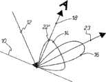
图1一个在定向白光照射时的光学变化平面图案,用于表明一个薄膜结构与两个各向同性无光泽结构结合的效果,Figure 1. An optically changing planar pattern under directional white light illumination to demonstrate the effect of combining a thin-film structure with two isotropic matte structures,
图2与图1类似的视图,但是与图1相比光学变化平面图案被倾翻,Figure 2 is a view similar to Figure 1, but with the optically changing planar pattern inverted compared to Figure 1,
图3一个具有一个薄膜结构的非对称消色差结构和一个平面薄膜结构的示意图。Figure 3. Schematic representation of an asymmetric achromatic structure with a thin film structure and a planar thin film structure.
具体实施方式Detailed ways
图1示出一个包括一个平面图案的衬底10,它具有一个薄膜结构与两个各向同性无光泽结构的组合。指向衬底10的箭头12表示一个定向的白光照射。例如当光线来自一个与衬底10相对较远间隔的光源时,呈现这种定向照射。Figure 1 shows a
所述衬底10的两个无光泽结构在其平均深度和/或在其相关长度上是不同的,因此一个无光泽结构比另一无光泽结构使定向入射的白光在一个更大的角度范围上散射。具有较大角度范围的无光泽结构的散射锥以标记符号14表示而另一无光泽结构的散射锥以标记符号16表示。The two matt structures of the
假设薄膜的特性与无光泽结构的特性相互间几乎是无关的,则产生优点,即,在一个定向照射时表示特征的色彩突变对于使用者更易于识别,因为色彩突变不只在镜反射中显示。Assuming that the properties of the film and the properties of the matte structure are virtually independent of one another, the advantage arises that the characteristic color change is easier to recognize for the user when illuminated from one direction, since the color change is not only displayed in specular reflection.
通过标记符号18表示观察方向,即使用者对于衬底10的视线方向。观察者必需使衬底10倾翻并这样定位,使光源在镜反射中显现。通过薄膜结构与两个无光泽结构重叠使可以识别到薄膜效应的观察范围以有利的方式变大。按照图1例如衬底10的覆有带散射锥16的无光泽结构的部分表面可以看到亮红色,即其中薄膜色是具有相应较大强度的红色。被具有散射锥14的无光泽结构所覆盖的那些部分表面尽管同样显示出红色,但是由于较大的散射范围显得更暗,因为强度在由箭头18表示的观察方向上相应减小。这一点通过点20和22表明。The viewing direction, ie the direction of the user's line of sight to the
在如图2所示倾翻衬底10时实现从薄膜反射的定向白光照射12例如向绿色变换,这一点通过箭头23表示。通过箭头12表示的定向白光照射和通过箭头18表示的构成方向保持不变。When the
此外由于根据两个无光泽结构的散射锥14和散射锥16的不同的散射特性,原先较明亮的部分表面按照图1中的点20显得较暗而原先按照点22较暗的部分表面对应于图2中的点22′显得较亮。在此通过薄膜给出具体的色彩结构。当然只是示例性地给出从红到绿的色彩变换。除了色彩变换以外以有利的方式也在相对亮度上实现对比变换。色彩变换和对比变换的这两种效果可以有利地作为参考并因此对于观察者允许一个简单的交流。In addition, due to the different scattering properties of the scattering
图3简示出一个薄膜结构24与一个非对称消色差结构的结合。在此通过标记符号26表示一个平面图案,由两个不同的平面元件28和30组成,它们相互邻接。区域32表示一个带有一种锯齿形倾翻薄膜结构的布置,而区域34示意性地表示一个平面薄膜结构。两个薄膜结构32和34的不同光学作用主要由此实现,对于倾翻的薄膜结构32在对于光学效果起决定性作用的薄膜厚度Deff与物理蒸镀的层厚Dphys之间存在差别。与此相反,对于平面的薄膜结构34在对于光学效果起决定性作用的薄膜厚度Deff与物理蒸镀的层厚Dphys之间没有差别。根据对于薄膜是否选择一个具有高折射率的材料或者具有低折射率的材料,通过这种薄膜结构24能够以有利的方式产生两个不同的效果。薄层的光学特性例如在由伦敦Butterworths Scientific Publication 1955年出版的O.S.Heavens撰写的书籍“Optical properties of thin solid films”第154及其下页中描述。Figure 3 schematically shows the combination of a
对于一个具有高折射率的薄膜材料可以实现,部分表面具有不同的色彩并且这些色彩在一个相对较大的倾翻角范围上是稳定的。对于一个具有低折射率的薄膜材料可以实现一个非对称的色彩跃变(Flip),即,一个部分表面28或30在倾翻时例如显示出一个从红到绿的色彩突变,而另一部分表面30或28显示出从绿到红的色彩突变。但是在这样一个倾翻后一个部分表面的红色与另一部分表面的红色不是一致的,而是略有不同。相应地对于绿色或其它颜色也相应有效。For a thin-film material with a high refractive index it is possible to have partial surfaces with different colors and these colors to be stable over a relatively large range of tilt angles. An asymmetric color jump (Flip) can be realized for a film material with a low refractive index, that is, a part of the
因此,消色差衍射效果被包括给定的色彩跃变的薄膜干涉效应重叠,由此可靠地提供一个确定的色彩变换。通过按照本发明的作用确定的色彩变换克服在一种已知的连续色彩变换中所存在的或难以排除的确定性问题。Thus, the achromatic diffractive effect is superimposed by the thin-film interference effect comprising a given color jump, thereby reliably providing a defined color shift. The deterministic problems that are present or difficult to eliminate in a known continuous color transformation are overcome by the color transformation determined according to the effect of the invention.
Claims (12)
Applications Claiming Priority (2)
| Application Number | Priority Date | Filing Date | Title |
|---|---|---|---|
| DE10221491.3 | 2002-05-14 | ||
| DE10221491ADE10221491A1 (en) | 2002-05-14 | 2002-05-14 | Optically variable surface pattern |
Publications (2)
| Publication Number | Publication Date |
|---|---|
| CN1662389A CN1662389A (en) | 2005-08-31 |
| CN100526091Ctrue CN100526091C (en) | 2009-08-12 |
Family
ID=29413821
Family Applications (1)
| Application Number | Title | Priority Date | Filing Date |
|---|---|---|---|
| CNB038142384ACeasedCN100526091C (en) | 2002-05-14 | 2003-05-09 | Optically variable element |
Country Status (13)
| Country | Link |
|---|---|
| US (1) | US7215450B2 (en) |
| EP (1) | EP1506096B1 (en) |
| JP (1) | JP4405913B2 (en) |
| KR (1) | KR100972406B1 (en) |
| CN (1) | CN100526091C (en) |
| AT (1) | ATE408522T1 (en) |
| AU (1) | AU2003245819A1 (en) |
| DE (2) | DE10221491A1 (en) |
| DK (1) | DK1506096T3 (en) |
| ES (1) | ES2314214T3 (en) |
| PL (1) | PL203166B1 (en) |
| RU (1) | RU2314210C2 (en) |
| WO (1) | WO2003095657A2 (en) |
Families Citing this family (34)
| Publication number | Priority date | Publication date | Assignee | Title |
|---|---|---|---|---|
| DE102004003984A1 (en)† | 2004-01-26 | 2005-08-11 | Giesecke & Devrient Gmbh | Lattice image with one or more grid fields |
| DE102004016596B4 (en) | 2004-04-03 | 2006-07-27 | Ovd Kinegram Ag | Security element in the form of a multilayer film body and method for producing a security element |
| AU2005263239B2 (en)* | 2004-07-21 | 2011-04-07 | Rolic Ag | Anisotropic optical devices and method for making same |
| DE102005061749A1 (en) | 2005-12-21 | 2007-07-05 | Giesecke & Devrient Gmbh | Optically variable security element for making valuable objects safe has an achromatic reflecting micro-structure taking the form of a mosaic made from achromatic reflecting mosaic elements |
| EP1855127A1 (en)* | 2006-05-12 | 2007-11-14 | Rolic AG | Optically effective surface relief microstructures and method of making them |
| GB0613306D0 (en)* | 2006-07-04 | 2006-08-16 | Rue De Int Ltd | Security device |
| AU2008201903B2 (en)† | 2007-05-07 | 2013-03-28 | Viavi Solutions Inc. | Structured surfaces that exhibit color by rotation |
| DE102007061828A1 (en)* | 2007-12-20 | 2009-06-25 | Giesecke & Devrient Gmbh | Security element and method for its production |
| DE102007061827A1 (en) | 2007-12-20 | 2009-06-25 | Giesecke & Devrient Gmbh | Security element and method for its production |
| DE102008009296A1 (en)* | 2008-02-15 | 2009-08-20 | Giesecke & Devrient Gmbh | Security element and method for its production |
| DE102008013167A1 (en)* | 2008-03-07 | 2009-09-10 | Giesecke & Devrient Gmbh | Security element and method for its production |
| EP3236299B1 (en) | 2008-09-05 | 2024-07-03 | Viavi Solutions Inc. | An optical device exhibiting color shift upon rotation |
| DE102009056934A1 (en)* | 2009-12-04 | 2011-06-09 | Giesecke & Devrient Gmbh | Security element, value document with such a security element and manufacturing method of a security element |
| FR2968239B1 (en)* | 2010-12-07 | 2012-12-21 | Hologram Ind | SECURE PRODUCT AND METHOD OF MAKING SAID SECURE PRODUCT |
| DE102011014114B3 (en)* | 2011-03-15 | 2012-05-10 | Ovd Kinegram Ag | Multi-layer body and method for producing a multi-layer body |
| FR2989474B1 (en)* | 2012-04-13 | 2014-11-28 | Hologram Ind | OPTICAL SECURITY COMPONENT, MANUFACTURE OF SUCH A COMPONENT, AND SECURE PRODUCT EQUIPPED WITH SUCH A COMPONENT |
| DE102012020550A1 (en)* | 2012-10-19 | 2014-04-24 | Giesecke & Devrient Gmbh | Optically variable surface pattern |
| DE102013208628A1 (en) | 2013-05-10 | 2014-11-13 | Gneuss Gmbh | Method for operating a Siebradfilters and Siebradfilter for performing the method |
| GB201400910D0 (en)* | 2014-01-20 | 2014-03-05 | Rue De Int Ltd | Security elements and methods of their manufacture |
| US20170267846A1 (en) | 2016-03-15 | 2017-09-21 | Nike, Inc. | Foam compositions and uses thereof |
| WO2019067928A2 (en) | 2017-09-29 | 2019-04-04 | Nike Innovate C.V. | Structurally-colored articles and methods of making and using structurally-colored articles |
| WO2019178150A1 (en) | 2018-03-12 | 2019-09-19 | Nike Innovate C.V. | Thermoplastic foam articles |
| CN112533506B (en) | 2018-06-04 | 2023-03-28 | 耐克创新有限合伙公司 | Two-part sole structure and use thereof |
| JP2022502283A (en)* | 2018-09-24 | 2022-01-11 | オーファウデー キネグラム アーゲー | Optical variable element, security document, optical variable element manufacturing method, security document manufacturing method |
| WO2020117829A1 (en) | 2018-12-03 | 2020-06-11 | Nike Innovate C.V. | High energy return foam compositions having improved abrasion resistance and uses thereof |
| WO2020263362A1 (en) | 2019-06-26 | 2020-12-30 | Nike Innovate C.V. | Structurally-colored articles and methods for making and using structurally-colored articles |
| US20210022444A1 (en) | 2019-07-26 | 2021-01-28 | Nike, Inc. | Structurally-colored articles and methods for making and using structurally-colored articles |
| US11447615B2 (en) | 2019-09-12 | 2022-09-20 | Nike, Inc. | Foam compositions and uses thereof |
| GB2600855B (en) | 2019-09-12 | 2024-05-29 | Nike Innovate Cv | A cushioning element for an article of footwear |
| US20210109265A1 (en)* | 2019-10-15 | 2021-04-15 | Nike, Inc. | Structurally-colored articles and methods for making and using structurally-colored articles |
| US11241062B1 (en) | 2020-08-07 | 2022-02-08 | Nike, Inc. | Footwear article having repurposed material with structural-color concealing layer |
| US11129444B1 (en) | 2020-08-07 | 2021-09-28 | Nike, Inc. | Footwear article having repurposed material with concealing layer |
| US11889894B2 (en) | 2020-08-07 | 2024-02-06 | Nike, Inc. | Footwear article having concealing layer |
| DE102020006902A1 (en) | 2020-11-10 | 2022-05-12 | Giesecke+Devrient Currency Technology Gmbh | Optically variable security element and method for producing an optically variable security element |
Citations (4)
| Publication number | Priority date | Publication date | Assignee | Title |
|---|---|---|---|---|
| US4568141A (en)* | 1982-10-04 | 1986-02-04 | Lgz Landis & Gyr Zug Ag | Document having an optical-diffraction authenticating element |
| US5032003A (en)* | 1988-12-12 | 1991-07-16 | Landis & Gyr Betriebs Ag | Optially variable surface pattern |
| US6157487A (en)* | 1995-11-28 | 2000-12-05 | Ovd Kinegram Ag | Optically variable surface pattern |
| US20010043396A1 (en)* | 1998-07-02 | 2001-11-22 | Lee Robert Arthur | Diffractive structure with interstitial elements |
Family Cites Families (8)
| Publication number | Priority date | Publication date | Assignee | Title |
|---|---|---|---|---|
| US3858977A (en)* | 1972-01-18 | 1975-01-07 | Canadian Patents Dev | Optical interference authenticating means |
| EP0201323B1 (en) | 1985-05-07 | 1994-08-17 | Dai Nippon Insatsu Kabushiki Kaisha | Article incorporating a transparent hologramm |
| JP3392500B2 (en)* | 1994-02-28 | 2003-03-31 | 凸版印刷株式会社 | Display with diffraction grating pattern |
| DE4432062C1 (en) | 1994-09-09 | 1995-11-30 | Kurz Leonhard Fa | Visually identifiable optical security element for credit cards etc. |
| JP4390913B2 (en)* | 1999-06-25 | 2009-12-24 | 大日本印刷株式会社 | Anti-counterfeit thread and anti-counterfeit paper using the same |
| EP1275084B1 (en) | 2000-04-15 | 2007-08-08 | OVD Kinegram AG | Pattern |
| DE10129939B4 (en)* | 2001-06-20 | 2006-06-22 | Ovd Kinegram Ag | Optically variable surface pattern |
| DE50213436D1 (en)* | 2001-12-22 | 2009-05-20 | Ovd Kinegram Ag | DIFFUSER SECURITY ELEMENT |
- 2002
- 2002-05-14DEDE10221491Apatent/DE10221491A1/ennot_activeWithdrawn
- 2003
- 2003-05-09CNCNB038142384Apatent/CN100526091C/ennot_activeCeased
- 2003-05-09USUS10/514,370patent/US7215450B2/ennot_activeExpired - Lifetime
- 2003-05-09ATAT03737876Tpatent/ATE408522T1/enactive
- 2003-05-09DEDE50310522Tpatent/DE50310522D1/ennot_activeExpired - Lifetime
- 2003-05-09DKDK03737876Tpatent/DK1506096T3/enactive
- 2003-05-09PLPL372447Apatent/PL203166B1/enunknown
- 2003-05-09JPJP2004503647Apatent/JP4405913B2/ennot_activeExpired - Fee Related
- 2003-05-09EPEP03737876Apatent/EP1506096B1/ennot_activeExpired - Lifetime
- 2003-05-09ESES03737876Tpatent/ES2314214T3/ennot_activeExpired - Lifetime
- 2003-05-09RURU2004136313/11Apatent/RU2314210C2/enactive
- 2003-05-09KRKR1020047018313Apatent/KR100972406B1/ennot_activeExpired - Fee Related
- 2003-05-09AUAU2003245819Apatent/AU2003245819A1/ennot_activeAbandoned
- 2003-05-09WOPCT/DE2003/001483patent/WO2003095657A2/enactiveIP Right Grant
Patent Citations (4)
| Publication number | Priority date | Publication date | Assignee | Title |
|---|---|---|---|---|
| US4568141A (en)* | 1982-10-04 | 1986-02-04 | Lgz Landis & Gyr Zug Ag | Document having an optical-diffraction authenticating element |
| US5032003A (en)* | 1988-12-12 | 1991-07-16 | Landis & Gyr Betriebs Ag | Optially variable surface pattern |
| US6157487A (en)* | 1995-11-28 | 2000-12-05 | Ovd Kinegram Ag | Optically variable surface pattern |
| US20010043396A1 (en)* | 1998-07-02 | 2001-11-22 | Lee Robert Arthur | Diffractive structure with interstitial elements |
Also Published As
| Publication number | Publication date |
|---|---|
| RU2314210C2 (en) | 2008-01-10 |
| WO2003095657A3 (en) | 2004-04-08 |
| KR100972406B1 (en) | 2010-07-26 |
| PL203166B1 (en) | 2009-08-31 |
| KR20050007541A (en) | 2005-01-19 |
| US7215450B2 (en) | 2007-05-08 |
| RU2004136313A (en) | 2005-05-10 |
| CN1662389A (en) | 2005-08-31 |
| PL372447A1 (en) | 2005-07-25 |
| DK1506096T3 (en) | 2009-01-26 |
| DE10221491A1 (en) | 2003-12-04 |
| ATE408522T1 (en) | 2008-10-15 |
| WO2003095657A2 (en) | 2003-11-20 |
| JP2005525593A (en) | 2005-08-25 |
| AU2003245819A1 (en) | 2003-11-11 |
| US20050168723A1 (en) | 2005-08-04 |
| AU2003245819A8 (en) | 2003-11-11 |
| JP4405913B2 (en) | 2010-01-27 |
| DE50310522D1 (en) | 2008-10-30 |
| EP1506096B1 (en) | 2008-09-17 |
| ES2314214T3 (en) | 2009-03-16 |
| EP1506096A2 (en) | 2005-02-16 |
Similar Documents
| Publication | Publication Date | Title |
|---|---|---|
| CN100526091C (en) | Optically variable element | |
| US10427368B2 (en) | Multi-layer body | |
| JP5695357B2 (en) | Security elements with micro and macro structures | |
| US9465148B2 (en) | Security document | |
| CA2780934C (en) | Security element, value document having such a security element, and manufacturing method for a security element | |
| US10207531B2 (en) | Security device | |
| RU2314931C2 (en) | Protection element, provided with macro-structure | |
| AU2014250638A1 (en) | Security element, value document comprising such a security element, and method for producing such a security element | |
| US11345178B2 (en) | Security element, and method for producing a security element | |
| TWI815976B (en) | Optically changeable element, anti-counterfeiting document, manufacturing method of optically changeable element, anti-counterfeiting document manufacturing method | |
| CN111757812B (en) | Optically variable security element with reflective surface area | |
| CN111032364B (en) | Optically variable see-through security elements and data carriers | |
| US20240190159A1 (en) | Optically variable security element, and value document containing the optically variable security element | |
| HK1182773B (en) | Security element comprising an optically variable surface pattern |
Legal Events
| Date | Code | Title | Description |
|---|---|---|---|
| C06 | Publication | ||
| PB01 | Publication | ||
| C10 | Entry into substantive examination | ||
| SE01 | Entry into force of request for substantive examination | ||
| C14 | Grant of patent or utility model | ||
| GR01 | Patent grant | ||
| CP01 | Change in the name or title of a patent holder | Address after:Fuerth Germany Patentee after:Leonhard Kurz Stiftung & Co. KG Address before:Fuerth Germany Patentee before:Leonhard Kurz GmbH & Co. | |
| CP01 | Change in the name or title of a patent holder | ||
| IW01 | Full invalidation of patent right | Decision date of declaring invalidation:20180713 Decision number of declaring invalidation:36593 Granted publication date:20090812 | |
| IW01 | Full invalidation of patent right |