CN100522281C - Catheter - Google Patents
CatheterDownload PDFInfo
- Publication number
- CN100522281C CN100522281CCNB038268868ACN03826886ACN100522281CCN 100522281 CCN100522281 CCN 100522281CCN B038268868 ACNB038268868 ACN B038268868ACN 03826886 ACN03826886 ACN 03826886ACN 100522281 CCN100522281 CCN 100522281C
- Authority
- CN
- China
- Prior art keywords
- needle
- remaining needle
- syringe needle
- pin lid
- remaining
- Prior art date
- Legal status (The legal status is an assumption and is not a legal conclusion. Google has not performed a legal analysis and makes no representation as to the accuracy of the status listed.)
- Expired - Fee Related
Links
- 238000002347injectionMethods0.000claimsabstractdescription51
- 239000007924injectionSubstances0.000claimsabstractdescription51
- 230000000903blocking effectEffects0.000claimsdescription12
- 230000000694effectsEffects0.000claimsdescription4
- 230000008878couplingEffects0.000claims3
- 238000010168coupling processMethods0.000claims3
- 238000005859coupling reactionMethods0.000claims3
- 239000013013elastic materialSubstances0.000claims1
- 238000010586diagramMethods0.000description25
- 238000005452bendingMethods0.000description6
- 238000003780insertionMethods0.000description6
- 230000037431insertionEffects0.000description6
- 238000010992refluxMethods0.000description4
- 239000008280bloodSubstances0.000description3
- 210000004369bloodAnatomy0.000description3
- 239000007788liquidSubstances0.000description2
- 230000000087stabilizing effectEffects0.000description2
- 230000004308accommodationEffects0.000description1
- 230000000740bleeding effectEffects0.000description1
- 230000007812deficiencyEffects0.000description1
- 230000001788irregularEffects0.000description1
- 238000000034methodMethods0.000description1
Images


Classifications
- A—HUMAN NECESSITIES
- A61—MEDICAL OR VETERINARY SCIENCE; HYGIENE
- A61M—DEVICES FOR INTRODUCING MEDIA INTO, OR ONTO, THE BODY; DEVICES FOR TRANSDUCING BODY MEDIA OR FOR TAKING MEDIA FROM THE BODY; DEVICES FOR PRODUCING OR ENDING SLEEP OR STUPOR
- A61M25/00—Catheters; Hollow probes
- A61M25/01—Introducing, guiding, advancing, emplacing or holding catheters
- A61M25/06—Body-piercing guide needles or the like
- A61M25/0612—Devices for protecting the needle; Devices to help insertion of the needle, e.g. wings or holders
- A61M25/0631—Devices for protecting the needle; Devices to help insertion of the needle, e.g. wings or holders having means for fully covering the needle after its withdrawal, e.g. needle being withdrawn inside the handle or a cover being advanced over the needle
- A—HUMAN NECESSITIES
- A61—MEDICAL OR VETERINARY SCIENCE; HYGIENE
- A61M—DEVICES FOR INTRODUCING MEDIA INTO, OR ONTO, THE BODY; DEVICES FOR TRANSDUCING BODY MEDIA OR FOR TAKING MEDIA FROM THE BODY; DEVICES FOR PRODUCING OR ENDING SLEEP OR STUPOR
- A61M5/00—Devices for bringing media into the body in a subcutaneous, intra-vascular or intramuscular way; Accessories therefor, e.g. filling or cleaning devices, arm-rests
- A61M5/178—Syringes
- A61M5/31—Details
- A61M5/32—Needles; Details of needles pertaining to their connection with syringe or hub; Accessories for bringing the needle into, or holding the needle on, the body; Devices for protection of needles
- A61M5/3205—Apparatus for removing or disposing of used needles or syringes, e.g. containers; Means for protection against accidental injuries from used needles
- A61M5/321—Means for protection against accidental injuries by used needles
- A61M5/3243—Means for protection against accidental injuries by used needles being axially-extensible, e.g. protective sleeves coaxially slidable on the syringe barrel
- A61M5/3271—Means for protection against accidental injuries by used needles being axially-extensible, e.g. protective sleeves coaxially slidable on the syringe barrel with guiding tracks for controlled sliding of needle protective sleeve from needle exposing to needle covering position
- A61M5/3272—Means for protection against accidental injuries by used needles being axially-extensible, e.g. protective sleeves coaxially slidable on the syringe barrel with guiding tracks for controlled sliding of needle protective sleeve from needle exposing to needle covering position having projections following labyrinth paths
Landscapes
- Health & Medical Sciences (AREA)
- Life Sciences & Earth Sciences (AREA)
- Biophysics (AREA)
- Pulmonology (AREA)
- Engineering & Computer Science (AREA)
- Anesthesiology (AREA)
- Biomedical Technology (AREA)
- Heart & Thoracic Surgery (AREA)
- Hematology (AREA)
- Animal Behavior & Ethology (AREA)
- General Health & Medical Sciences (AREA)
- Public Health (AREA)
- Veterinary Medicine (AREA)
- Infusion, Injection, And Reservoir Apparatuses (AREA)
Abstract
Description
Translated fromChinese技术领域technical field
本发明是关于留置针结构,特别是指一种可避免医謢人员操作时发生危险之留置针结构。The present invention relates to an indwelling needle structure, in particular to an indwelling needle structure that can avoid danger during operation by medical personnel.
背景技术Background technique
一般现有的留置针结构包括一针头、一留置针及一针盖,其中该留置针是套置于针头上,而针盖则包覆于针头前端及留置针外缘,当此现有的留置针结构使用时,是先将针盖取下,将针头连同留置针以针头上的注射针插入患者的注射部,再按押住留置针的软管及套管,然后将针头抽出,使留置针留在患者的注射部而与针头分离,然后再以一输送管穿设于留置针的套管内进行注射;但是,此种留置针结构在针头与留置针分离时,患者的血液会自留置针处涌出,因此医护人员在将针头抽出然后将输送管插设于留置针的套管时,速度要非常快,以免患者的血液流出太多,然而,亦由于医护人员在抽换针头与输送管时的速度要快,因此很容易导致医护人员被抽出的针头的注射针划伤而产生危险。Generally, the existing indwelling needle structure includes a needle head, an indwelling needle and a needle cover, wherein the indwelling needle is sleeved on the needle head, and the needle cover covers the front end of the needle head and the outer edge of the indwelling needle. When the indwelling needle structure is used, the needle cover is removed first, the needle and the indwelling needle are inserted into the injection part of the patient with the injection needle on the needle, and then the hose and cannula of the indwelling needle are pressed, and then the needle is pulled out so that The indwelling needle is left in the injection part of the patient and separated from the needle, and then a delivery tube is passed through the cannula of the indwelling needle for injection; however, when the needle is separated from the indwelling needle structure, the blood of the patient will automatically Therefore, when the medical staff pulls out the needle and then inserts the delivery tube into the cannula of the indwelling needle, the speed must be very fast to prevent the patient from bleeding too much. The speed with the delivery tube should be fast, so it is easy to cause the medical staff to be scratched by the injection needle of the withdrawn needle and cause danger.
由此可见,上述现有物品仍有诸多缺失,实非一优良的设计,而亟待加以改良。This shows that above-mentioned existing article still has many deficiencies, is really not a fine design, and urgently needs to be improved.
本发明人鉴于上述现有留置针结构所衍生的各项缺点,乃亟思加以改良创新,并经多年苦心孤诣潜心研究后,终于成功研发完成本件留置针结构。In view of the various shortcomings derived from the above-mentioned existing indwelling needle structure, the inventor desperately wanted to improve and innovate, and after years of painstaking research, he finally successfully developed and completed the indwelling needle structure.
发明内容Contents of the invention
本发明的目的在于提供一种可避免医护人员在操作时发生危险的留置针结构。The purpose of the present invention is to provide an indwelling needle structure that can avoid dangers for medical personnel during operation.
本发明的另一目的是在于提供一种可防止针头与留置针分离时,针头顺着针盖的滑槽至倾斜部时,将注射针倾斜一角度,以避免医护人员在使用时发生危险的留置针结构。Another object of the present invention is to provide a device that can prevent the injection needle from being inclined at an angle when the needle head is separated from the indwelling needle along the chute of the needle cover to avoid danger when the medical staff uses it. Indwelling needle structure.
本发明的次一目的是在于提供一种可防止针头与留置针分离时,血液经由留置针倒流出来的留置针结构。Another object of the present invention is to provide an indwelling needle structure that can prevent blood from flowing backward through the indwelling needle when the needle is separated from the indwelling needle.
可达成上述发明目的的留置针结构,包括有:The indwelling needle structure that can achieve the purpose of the above invention includes:
一针头,该针头的侧缘设有一个或一个以上之扣件部,而针头之后方则塞设有一回流器;A needle with one or more fastening parts on the side edge of the needle and a reflux device plugged behind the needle;
一留置针,该留置针是于一套管前端延伸有一软管,而套管之后端外缘则环设有一抵挡部;An indwelling needle, the indwelling needle is extended with a flexible tube at the front end of the cannula, and a resisting portion is provided around the outer edge of the rear end of the cannula;
一针盖,该针盖前端开设有一开口,该开口前端设有若干勾设部,且该针盖之后端外缘对应针头的各扣件位置与数量延伸有数个滑移部,并于各滑移部上开设有一滑槽,而各滑槽接近末端之处有一向下倾斜部,向下倾斜部的前端有一凸点;A needle cover, the front end of the needle cover is provided with an opening, the front end of the opening is provided with a number of hooking parts, and the outer edge of the rear end of the needle cover corresponds to the positions and numbers of the fasteners of the needle head. There is a chute on the moving part, and there is a downward slope near the end of each chute, and there is a convex point at the front end of the downward slope;
该针头的扣件部则分别容置于针盖的各滑槽内,以便由该滑槽使针盖在针头上滑移,当使用完毕时,针盖的滑槽末端之处则形成一凸点,该凸点之后具有一倾斜部,使注射针因倾斜部而安全倾斜于针盖内,以避免医謢人员使用时不慎发生危险。The fastener part of the needle head is respectively accommodated in each chute of the needle cover so that the needle cover can slide on the needle head through the chute. There is an inclined part behind the convex point, so that the injection needle can be safely inclined in the needle cover due to the inclined part, so as to avoid accidental danger when medical personnel use it.
一种留置针结构,包括:An indwelling needle structure, comprising:
一针头,该针头前端插设有一注射针,且该针头的侧缘没有一个或一个以上的扣件,而针头之后方则塞设有一回流器A needle with an injection needle inserted into the front end of the needle, without one or more fasteners on the side edge of the needle, and a reflux device plugged behind the needle
一留置针,该留置针是于一套管前端延伸有一软管,而套管之后端外缘则环设有一抵挡部;An indwelling needle, the indwelling needle is extended with a flexible tube at the front end of the cannula, and a resisting portion is provided around the outer edge of the rear end of the cannula;
一针盖,该针盖之后端外缘对应针头的各扣件部位置与数量延伸有数个滑移部,并于各滑移部上开设有一滑槽,而各滑槽接近末端之处则形成一凸点;A needle cover, the outer edge of the rear end of the needle cover corresponds to the position and quantity of each fastener part of the needle, and several sliding parts are extended, and a chute is opened on each sliding part, and each chute is formed near the end. a bump;
该针盖是套设于针头前端,该针头上的注射针则贯穿该针盖,且该留置针是以套管套设于针盖上,而该针头的各扣件部则分别容置于针盖的各滑槽内,以便由该滑槽使插设部在针头上滑移。The needle cover is sleeved on the front end of the needle head, and the injection needle on the needle head passes through the needle cover, and the indwelling needle is sleeved on the needle cover with a sleeve, and each fastener part of the needle head is respectively accommodated in the needle cover. Each chute of the needle cover, so that the insertion part can slide on the needle through the chute.
附图说明Description of drawings
请参阅以下有关本发明一较佳实施例的详细说明及其附图,将可进一步了解本发明的技术内容及其目的功效;有关该实施例的附图为:Please refer to the following detailed description of a preferred embodiment of the present invention and the accompanying drawings, will further understand the technical content of the present invention and its purpose effect; the accompanying drawings of the relevant embodiment are:
图1为该留置针结构的第一种立体分解图;Fig. 1 is the first three-dimensional exploded view of the indwelling needle structure;
图1(A)为该留置针结构的第二种立体分解图;Fig. 1 (A) is the second three-dimensional exploded view of the indwelling needle structure;
图1(B)为该留置针结构的第三种立体分解图;Fig. 1 (B) is the third three-dimensional exploded view of the indwelling needle structure;
图2为该留置针结构的示意图;Figure 2 is a schematic diagram of the structure of the indwelling needle;
图3为该留置针结构第一实施例的示意图;Fig. 3 is a schematic diagram of the first embodiment of the indwelling needle structure;
图4为该留置针结构第二实施例的示意图;Fig. 4 is a schematic diagram of the second embodiment of the indwelling needle structure;
图5为该留置针结构第三实施例的示意图;Fig. 5 is a schematic diagram of the third embodiment of the indwelling needle structure;
图6为该留置针结构第四实施例的示意图;Fig. 6 is a schematic diagram of a fourth embodiment of the indwelling needle structure;
图7为该留置针结构第五实施例的示意图;Fig. 7 is a schematic diagram of the fifth embodiment of the indwelling needle structure;
图8为该留置针结构第六实施例的示意图;Fig. 8 is a schematic diagram of the sixth embodiment of the indwelling needle structure;
图9为该留置针结构第七实施例的示意图;Fig. 9 is a schematic diagram of a seventh embodiment of the indwelling needle structure;
图9(A)为该留置针结构第八实施例的示意图;Fig. 9 (A) is the schematic diagram of the eighth embodiment of the indwelling needle structure;
图10为该留置针结构第九实施例的示意图;Fig. 10 is a schematic diagram of the ninth embodiment of the indwelling needle structure;
图10(A)为该留置针结构第十实施例的示意图;Fig. 10(A) is a schematic diagram of the tenth embodiment of the indwelling needle structure;
图11为另一留置针结构的立体分解图;Fig. 11 is a three-dimensional exploded view of another indwelling needle structure;
图12为另一留置针结构第一实施例的示意图;Fig. 12 is a schematic diagram of the first embodiment of another indwelling needle structure;
图12(A)为另一留置针结构第二实施例的示意图;Fig. 12 (A) is the schematic diagram of the second embodiment of another indwelling needle structure;
图12(B)为另一留置针结构第三实施例的示意图;Fig. 12(B) is a schematic diagram of another third embodiment of the indwelling needle structure;
图12(C)为另一留置针结构第四实施例的示意图;Fig. 12(C) is a schematic diagram of another fourth embodiment of the indwelling needle structure;
图13为另一留置针结构第五实施例的示意图;Fig. 13 is a schematic diagram of another fifth embodiment of the indwelling needle structure;
图14为另一留置针结构第六实施例的示意图;Fig. 14 is a schematic diagram of another sixth embodiment of the indwelling needle structure;
图15为该留置针结构第九实施例的示意图;Fig. 15 is a schematic diagram of the ninth embodiment of the indwelling needle structure;
图16为该留置针结构第十一实施例的示意图;Fig. 16 is a schematic diagram of an eleventh embodiment of the indwelling needle structure;
图17为该留置针结构第十二实施例的示意图;Fig. 17 is a schematic diagram of a twelfth embodiment of the indwelling needle structure;
图18为另一留置针结构第七实施例的示意图;Fig. 18 is a schematic diagram of another seventh embodiment of an indwelling needle structure;
图19为该留置针结构第十三实施例的示意图。Fig. 19 is a schematic diagram of a thirteenth embodiment of the indwelling needle structure.
图20为该留置针结构的留置针第一实施例的示意图;Fig. 20 is a schematic diagram of the first embodiment of the indwelling needle of the indwelling needle structure;
图21为该留置针结构的留置针第二实施例的示意图;Fig. 21 is a schematic diagram of the second embodiment of the indwelling needle of the indwelling needle structure;
图22为该留置针结构的留置针第三实施例的示意图。Fig. 22 is a schematic diagram of a third embodiment of the indwelling needle of the indwelling needle structure.
具体实施方式Detailed ways
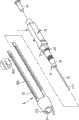
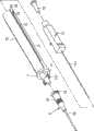
请参阅图1、图1(A)、图1(B)、图3及图15所示,本发明所提供的留置针结构,主要包括有:Please refer to Fig. 1, Fig. 1(A), Fig. 1(B), Fig. 3 and Fig. 15, the indwelling needle structure provided by the present invention mainly includes:
一针头1,该针头1前端具有一插设部11,该插设部11上插设有一注射针111,且该针头1的侧缘设有一个或一个以上的扣件部12,而针投1的后方则塞设有一回流器13;A needle 1, the front end of the needle 1 has an
一留置针2,该留置针2是于一套管21前端延伸有一软管22而套管21之后端外缘则环设有一抵挡部23,该留置针2是以套管21套设计于针头1的插设部11,且针头1上的注射针111则容置于留置针2的软管22内;An indwelling
一针盖3,该针盖3前端开设有一开口31,该开口31前端设有若干勾设部311、312,且该针盖3之后端外缘对应针头1的扣件部12位置与数量延伸有数个滑移部32,并于各滑移部32上开设有一滑槽321,而各滑槽321接近末端之处一凸点322,当针头1的扣件部12顺着针盖3的滑槽321至末端时,该凸点322用以加强卡住该扣件部12,以避免针头1的扣件部12滑出使注射针111伤及他人,另外,本发明的留置针结构亦可在针盖3的各滑移部32内缘设一外环套33套罩于注射针111外缘及该针盖3前端可设有一连接组件51与一盖子6连接。A
另外,其中该针盖3之后端外缘对应针头1的扣件部12位置与数量延伸有数个滑移部32,并于各滑移部32上开设有一滑槽321,而各滑槽321接近末端之处有一向下倾斜部323(如图1(B)所示),向下倾斜部323之前端有一凸点322,当针头1的扣件部12顺着针盖3的滑槽321至末端时进入该倾斜部323时,该凸点322用以加强卡住该扣件部12及该倾斜部323使注射针111倾斜一角度,以避免针头1的扣件部12滑出使注射针111伤及他人;另,该针盖3之后端外缘对应针头1的扣件部12位置与数量延伸有数个滑移部32,并于各滑移部32上开设有一滑槽321,而各滑槽321接近末端之处有一向下倾斜部323,并在倾斜部323之末端有一容置槽324(如图1所示),向下倾斜部323之前后端有一凸点322,当针头1的扣件部12顺着针盖3的滑槽321至末端时进入该倾斜部323至容置槽324时,该凸点322用以加强卡住该扣件部12,以避免针头1的扣件部12滑出使注射针111伤及他人。In addition, the outer edge of the rear end of the
请参阅图2所示,当针头1与针盖3结合时,针头1的扣件部12顺着针盖3的滑槽321至末端时,该凸点322用以加强卡住该扣件部12,以避免针头1的扣件部12滑出使注射针111伤及他人;当使用时,针盖3的勾设部311、312与留置针2的抵挡部23交错扣勾,以固定留置针2之方向。Please refer to Figure 2, when the needle head 1 is combined with the
请参阅图3、图4及图5所示,本发明的留置针结构中,该针头1上的各扣件部12是容置于针盖3上的各滑槽321中,当本发明的留置针结构使用时,将针头1利用扣件部12在针盖3的滑槽321内滑移,由于滑槽321接近末端之处设有一倾斜部323及凸点322,因此必须略为施力方能使扣件部12通过该凸点322,该针头1利用扣件部12在针盖3的滑槽321内滑移,而使针盖3退于针头1之后方,共使注射针111及留置针2由针盖3的开口31处穿出,且当针盖3退至针头1后方时,该针盖3开口31前端的勾设部311为勾底于留置针2的抵挡部23前缘,此时,将注射针111连同留置针2的软管插入患者之注射部位,并按押住留置针2的套管21与软管22,再将针头1与留置针2分离并由注射部位拔出,使留置针2留置于注射部位,然后以一输送管插设于留置针2的套管21内进行注射,且由于针盖3的勾设部311、312勾抵于留置针2的抵挡部23前端外缘,因此当针头1与留置针2分离时,该针盖3会向前滑移而将注射针111包覆于针盖3内,此时再以较大之力量的将针盖3与留置针2分离,并由滑槽321末端的倾斜部323及凸点322将针头1的扣件部12固定,使针盖3保持将注射针111包覆住的状态;由此种结构,使得医护人员在使用留置针2时不会被注射针111划伤,而达到可避免医謢人员操作时发生危险之目的,另外,本发明针头1的扣件部12可为中空圆形状121,并与针盖3的滑移部32可为一条状滑管334所结合成一滑移结构;本发明针头1的扣件部可为一ㄇ型导轨14,该ㄇ型导轨14前端具有一倾斜部142,倾斜部142设置有一凸点141,并与针盖3的滑移部32末端有一凸块325,该凸块325设有一导孔326相结合成一滑移结构。Please refer to Fig. 3, Fig. 4 and Fig. 5, in the indwelling needle structure of the present invention, each
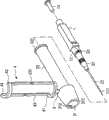
请参阅图6所示,本发明的留置针结构中,该针盖3前端安装一文件止结构4,该文件止结构4是由前挡块41、后挡块42及一个或一个以上之弯折片43所构成,该弯折片43是连接于前挡块41及后挡块42之间,且弯折片43中间均设有弯折部431,该前挡块41的前端透过连接组件5与针盖3结合,而后挡块42之后端则与针盖3的卡扣座331扣合。Please refer to Fig. 6, in the indwelling needle structure of the present invention, a
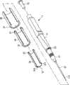
请参阅图7所示,本发明的留置针结构中该针头1上亦可不设扣件部12,而该针盖3则以一内缘套筒34、一个或一个以上之中间套筒35及一外缘套筒36代替,该中间套筒35是套于内缘套筒34外,而外缘套筒36是套置于中间套筒35外,其中,该外缘套筒36后端是套设于针头1外缘,且内缘套筒34及中间套筒35之后端外缘均凸设有一环凸部37,而外缘套筒36及中间套筒35的内缘前端亦各凸设有一环凸部37,再者,该内缘套筒34的内缘前端则设有若干勾设部311、312。Please refer to Fig. 7, in the indwelling needle structure of the present invention, the needle head 1 may not be provided with a
请参阅图8及图9所示,本发明的留置针结构中该针头1上亦可不设扣件部12,而于针头1内设有若干导槽16,且各导槽16为可供针盖3的各滑移部32穿入,并于任一滑移部32或各滑移部32后端设有数个止挡块327,其中该滑移部32可中心缕空,以利将滑移部32穿入针头1的导槽16,另外,该针头1的外缘可设有数个滑轨17,各滑轨17为可供针盖3后端之滑移部32穿入,并于任一滑移部32或各滑移部32后端设有数个止挡块327。其中该滑轨17前端设有一止挡块15。8 and 9, in the indwelling needle structure of the present invention, the needle head 1 may not be provided with a
请参阅图9A所示,本发明之留置针结构中,该针头1内设有若干滑槽17,且各滑槽17为可供针盖3的滑移部32穿入,该滑移部末端具有一凸块332,其中该针盖3的上端有一扣槽171,当针盖3的滑移部32穿入后,滑移部32的凸块332在滑移时,滑至针盖3的扣槽171内时,可固定针盖3以避免伤及他人。Please refer to FIG. 9A , in the indwelling needle structure of the present invention, the needle head 1 is provided with a plurality of sliding
请参阅图10及图10(A)所示,本发明的留置针结构中该针头1上亦可不设扣件部12,而于针头1外缘的前端凹设一挡置部181,针头1外缘之后端则凹设一容置部18,且针盖3及针头1的上端均加设一推片61,另外,针盖3的中心缕空并于针盖3的末端设有可勾设于容置部18及挡置部181内的扣勾38,使针盖3上之推片61滑移于针头1的前端或后端时,均可以便由针盖3的扣勾38勾设于针头1的容置部18或挡置部181,而使针盖3固定于针头1的前端或后端,且当本发明所提供的留置针使用完毕后,将针盖3以针盖上方的推片61,推至针头1的前端(或以针头1上方的推片61,将针投1向后拉),而使扣勾38勾设于挡置部181内,此时,该挡置部181之后侧壁面会抵顶于扣勾38后方,而使针盖3无法在往后推移,而使针盖3包覆于注射针111的外缘,以避免注射针111穿出而造成危险。Please refer to Fig. 10 and Fig. 10(A), in the indwelling needle structure of the present invention, the needle head 1 may not be provided with a
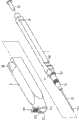
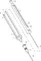
请参阅图11、图12、图12(A)、图12(B)及图12(C)所示,本发明所提供的留置针结构,主要包括有:Please refer to Figure 11, Figure 12, Figure 12(A), Figure 12(B) and Figure 12(C), the indwelling needle structure provided by the present invention mainly includes:
一针头1,该针头前端插设有一注射针111,且该针头1的侧缘设有一个或一个以上的扣件部12,而针头1之后方则塞设有一回流器13;A needle 1, an
一留置针2,该留置针是于一套管21前端延伸有一软管22,而套管21之后端外缘则环设有一抵挡部23;An
一针盖7,该针盖7之后端外缘对应针头1的各扣件部12位置与数量延伸有数个滑移部71,并于该滑移部71上开设有一滑槽72,而该滑槽72接近末端之处有一凸点74,当针头1的扣件部12顺着针盖7的滑槽72至末端时,该凸点74用以加强卡住该扣件部12,以避免针头1的扣件部12滑出使注射针111伤及他人;其中该滑槽末端之处有一向下倾斜部73,向下倾斜部73的前端有一凸点74,当针头1的扣件部12顺着针盖7的滑槽至倾斜73时,该倾斜部73使注射针111在针盖7产生一倾斜角度,以避免针头1的注射针111伤及他人,或该滑槽末端之处有一向下倾斜部73,向下倾斜部73设有一容置槽78,并于倾斜部73的末端设有一凸点74,当针头1的扣件部12顺着针盖7的滑槽72至倾斜部73的容置槽78时,该凸点74用以加强卡住该扣件部12,以避免针头1的扣件部12滑出使注射针111伤及他人。A
该针盖7是套设于针头1前端,该针头上的注射针则贯穿该针盖7,且该留置针2是以套管21套设于针盖7上,而该针头1的各扣件则分别容置于针盖7的各滑槽72内,以便由该滑槽72使针盖7在针头1上滑移,另外,本发明的留置针结构亦可在针盖7的各滑移部71内缘设一外环套75套罩于注射针111外缘。The
其中该针盖7的插设部11安置一个或一个以上的扣片112,该扣片112与留置针2的抵挡部23相扣合,以加强留置针2与针盖7之间的稳固作用;另外,亦可在针盖7的插设部11安置一个或一个以上的凸点191或凹点192,与留置针2的抵挡部23所安置一个或一个以上的凹点192或凸点191相密合,以加强留置2与针盖之间的稳固作用;再者,该凹点192亦可直接贯穿插设部11或抵挡部23。Wherein the
请参阅图13所示,本发明的留置针结构中该针头1上的扣件部12可以具圆孔的导引结构121代替,且针盖7后方的滑移部71则恰穿设于该导引结构121的圆孔内,并于各滑移部71的最末端则设有一倾斜部73,该倾斜部73前则设有一凸点74。Please refer to FIG. 13 , in the indwelling needle structure of the present invention, the
请参阅图14所示,本发明的留置针结构中该针头1亦可不设扣件部12,而于针头1的侧边延伸有若干ㄇ型导轨14,并于该ㄇ型导轨14接近前端的位置处设有一凸点141,另外,该针盖7后方的各滑移部71后端设有一具导孔77的凸块76,且各导孔77为穿设于各ㄇ导轨14。Please refer to Fig. 14, in the indwelling needle structure of the present invention, the needle head 1 may not be provided with a
请参阅16所示,本发明的留置针结构中该针盖3后端滑移部32的滑槽321开设有若干扣孔328,并于滑槽321与各扣孔328的相接处均设有凸圆329,而该针头1的扣件部12具有一弯折部122,该弯折部122的顶端则设有一可扣入扣孔328内的扣块123,本发明提供留置针结构使用前,是将弯折部122由扣孔328后端贯穿针盖3之处穿入并移动至滑槽321中,而使针盖3套设于针头1外缘,再将弯折部122一端的扣块123扣入滑槽321最后端的扣孔328中,并以便由滑槽321与扣孔328相接处之凸圆329抵顶扣块123,而将扣块123抵顶固定于扣孔328中,致使针盖3将注射针111包覆住;当本发明所提供的留置针结构欲使用时,仅需将扣块123与滑槽321后端的扣孔328分开即可使用。Please refer to 16, in the indwelling needle structure of the present invention, the
请参阅图17所示,本发明的留置针结构中,该针头1上的各扣件部12是容置于针盖3上的各滑槽321中,当本发明的留置针结构使用时,将针头1利用扣件12在针盖3的滑槽321内滑移,由于滑槽321接近末端之处设有一倾斜部323、容置槽324及凸点322,因此必须略为施力在推片61方能使扣件12通过该凸点322,该针头1利用扣件12在针盖3的滑槽321内滑移,而使针盖3退于针头1之后方,并令注射针111及留置针2由针盖3的开口31处穿出,且当针盖3退至针头1后方时,该针盖3开口31前端的勾设部311为勾抵于留置针2的抵挡部23前缘,此时,将注射针111连同留置针2的软管22插入患者的注射部位,因此当针头1与留置针2分离时,该针盖3会向前滑移而将注射针111包覆于针盖3内,此时再以较大的力量将针盖3与留置针2分离,并由滑槽321末端的倾斜部323及凸点322将针头1的扣件部12置于容置槽324内固定,而使针盖3保持将注射针111包覆住的状态。Please refer to Fig. 17, in the indwelling needle structure of the present invention, each
请参阅图18所示,本发明的留置针结构中该针头1上亦可不设扣件部12,而于针头内设有导槽16,且该导槽16与针盖3的滑移部32呈凹凸对应,该导槽16前端设有一止挡块15,与针盖3的滑移部32后端的止挡块155相扣合,以防止针头1与针盖3分离。Please refer to FIG. 18 , in the indwelling needle structure of the present invention, the needle head 1 may not be provided with a
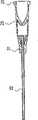
请参阅图19至图20所示,本发明的留置针结构中,该留置针2的内部可加装一舌片25,将注射针111抽离时,可接不同注射装置;另外,在该留置针2两侧加装一贴片24,该贴片24具有黏性,可附着在注射部位上。Please refer to Fig. 19 to Fig. 20, in the indwelling needle structure of the present invention, a
请参阅图21所示,本发明的留置针结构中,该留置针2之内部具有一舌片25,在该舌片25前端加一推块28,该推块28具有一中空管并介于舌片25及挡块29之间,当外接一物体抵住推块28时,该推块28将舌片25打开,以利注射液体流过。Please refer to Fig. 21, in the indwelling needle structure of the present invention, the indwelling
请参阅图22所示,本发明的留置针结构中,该留置针2的内部具有一弹簧26,再该弹簧26前端加一推块27,该推块27表面呈不规则平面并介于弹簧26及挡块29之间,当外接一物体抵住推块27进而压缩弹簧26时,该推块27离开档快29产生间隙,以利注射液体流过。Please refer to Figure 22, in the indwelling needle structure of the present invention, the indwelling
本发明所提供的留置针结构,与前述引证案及其它现有技术相互比较时,更具有下列的优点:The indwelling needle structure provided by the present invention has the following advantages when compared with the aforementioned cited case and other prior art:
一、本发明在将针头与留置针分离时,使针盖将注射针包覆住,而可避免医护人员在操作时发生危险。1. In the present invention, when the needle head is separated from the indwelling needle, the needle cover is used to cover the injection needle, so that the medical staff can avoid danger during operation.
二、本发明利用再留置针内设一止回结构或活塞,而可防止针头与留置针分离时,血液经由留置针倒流出来。2. The present invention uses a non-return structure or piston inside the indwelling needle to prevent blood from flowing backward through the indwelling needle when the needle is separated from the indwelling needle.
上列详细说明是针对本发明的ㄧ可行实施例的具体说明,但是该实施例并非用以限制本发明的专利范围,凡未脱离本发明技艺精神所为的等效实施或变更,均应包含于本案的专利范围中。The above detailed description is a specific description of a feasible embodiment of the present invention, but this embodiment is not intended to limit the patent scope of the present invention, and any equivalent implementation or change that does not depart from the technical spirit of the present invention shall include within the patent scope of this case.
Claims (37)
Applications Claiming Priority (1)
| Application Number | Priority Date | Filing Date | Title |
|---|---|---|---|
| PCT/CN2003/000727WO2005021082A1 (en) | 2003-08-28 | 2003-08-28 | A retained needle structure |
Publications (2)
| Publication Number | Publication Date |
|---|---|
| CN1819853A CN1819853A (en) | 2006-08-16 |
| CN100522281Ctrue CN100522281C (en) | 2009-08-05 |
Family
ID=34230862
Family Applications (1)
| Application Number | Title | Priority Date | Filing Date |
|---|---|---|---|
| CNB038268868AExpired - Fee RelatedCN100522281C (en) | 2003-08-28 | 2003-08-28 | Catheter |
Country Status (4)
| Country | Link |
|---|---|
| US (1) | US20070073219A1 (en) |
| CN (1) | CN100522281C (en) |
| AU (1) | AU2003261581A1 (en) |
| WO (1) | WO2005021082A1 (en) |
Cited By (1)
| Publication number | Priority date | Publication date | Assignee | Title |
|---|---|---|---|---|
| CN107530491A (en)* | 2015-05-12 | 2018-01-02 | 福建省百仕韦医用高分子股份有限公司 | The open indwelling needle of plane-of-weakness joint type protective case |
Families Citing this family (9)
| Publication number | Priority date | Publication date | Assignee | Title |
|---|---|---|---|---|
| JP2010214096A (en)* | 2009-02-19 | 2010-09-30 | Jms Co Ltd | Medical needle device |
| US20110306933A1 (en)* | 2010-06-11 | 2011-12-15 | Ilija Djordjevic | Safety cannula with automatic retractable needle |
| US8128594B1 (en)* | 2010-11-03 | 2012-03-06 | Chang li-feng | Safety syringe |
| US9480782B2 (en)* | 2013-01-14 | 2016-11-01 | R. Ashley Burrow | Surgical aspiration and irrigation |
| CN103127580B (en)* | 2013-03-14 | 2014-11-05 | 苏州大学 | Singlehanded safety indwelling needle |
| US12144519B2 (en) | 2014-04-03 | 2024-11-19 | Corbin Clinical Resources, Llc | Transperineal prostate biopsy and treatment methods |
| US10064681B2 (en) | 2014-04-03 | 2018-09-04 | Corbin Clinical Resources, Llc | Method, system, and device for planning and performing, guided and free-handed transperineal prostate biopsies |
| US10743909B2 (en) | 2014-04-03 | 2020-08-18 | Corbin Clinical Resources, Llc | Transperineal prostate biopsy device, systems, and methods of use |
| CN111481776B (en)* | 2020-05-07 | 2021-03-30 | 普昂(杭州)医疗科技有限公司 | Needle device, and protection structure and protection method thereof |
Citations (8)
| Publication number | Priority date | Publication date | Assignee | Title |
|---|---|---|---|---|
| US5520654A (en)* | 1992-11-26 | 1996-05-28 | Boc Ohmeda Ab | Catheter device |
| US5672160A (en)* | 1995-01-21 | 1997-09-30 | The Boc Group Plc | Medical devices |
| US5746733A (en)* | 1994-05-19 | 1998-05-05 | Becton, Dickinson And Company | Syringe filling and delivery device |
| US5797882A (en)* | 1996-08-23 | 1998-08-25 | Becton Dickinson And Company | Arterial catheter and catheter/needle assembly with improved flow characteristics and method for its use |
| US5954698A (en)* | 1997-01-08 | 1999-09-21 | Vadus, Inc. | Catheter apparatus having valved catheter hub and needle protector |
| US6080137A (en)* | 1997-01-08 | 2000-06-27 | Vadus, Inc. | Needle protector |
| US6213978B1 (en)* | 1998-10-27 | 2001-04-10 | Cherie A. Voyten | Intravenous catheter insertion apparatus |
| WO2002066093A2 (en)* | 2001-02-21 | 2002-08-29 | Serpomed Ltd. | Compact catheter insertion apparatus |
Family Cites Families (9)
| Publication number | Priority date | Publication date | Assignee | Title |
|---|---|---|---|---|
| US5356392A (en)* | 1990-05-09 | 1994-10-18 | Safety Syringes, Inc. | Shielded blood collection tube holder |
| US5279581A (en)* | 1990-05-09 | 1994-01-18 | Firth John R | Disposable self-shielding hypodermic syringe |
| US5176650A (en)* | 1992-02-10 | 1993-01-05 | Haining Michael L | Intravenous catheter and insertion device |
| GB2279570A (en)* | 1993-05-27 | 1995-01-11 | Kyung Jin Song | Vein needle set |
| US5456668A (en)* | 1994-01-14 | 1995-10-10 | F. H. Faulding & Co. Limited | Retractable venipuncture catheter needle and receptacle |
| DE9417600U1 (en)* | 1994-11-03 | 1994-12-22 | B. Braun Melsungen Ag, 34212 Melsungen | Protection device for a steel cannula |
| CA2209957C (en)* | 1996-07-22 | 2003-09-16 | Paul R. Capaccio | Syringe filling and delivery device |
| US7041086B2 (en)* | 2002-12-12 | 2006-05-09 | Chang-Ming Yang | Safety syringe needle |
| US20040116863A1 (en)* | 2002-12-12 | 2004-06-17 | Chang-Ming Yang | Intra-venous catheter structure |
- 2003
- 2003-08-28WOPCT/CN2003/000727patent/WO2005021082A1/enactiveApplication Filing
- 2003-08-28CNCNB038268868Apatent/CN100522281C/ennot_activeExpired - Fee Related
- 2003-08-28USUS10/569,623patent/US20070073219A1/ennot_activeAbandoned
- 2003-08-28AUAU2003261581Apatent/AU2003261581A1/ennot_activeAbandoned
Patent Citations (8)
| Publication number | Priority date | Publication date | Assignee | Title |
|---|---|---|---|---|
| US5520654A (en)* | 1992-11-26 | 1996-05-28 | Boc Ohmeda Ab | Catheter device |
| US5746733A (en)* | 1994-05-19 | 1998-05-05 | Becton, Dickinson And Company | Syringe filling and delivery device |
| US5672160A (en)* | 1995-01-21 | 1997-09-30 | The Boc Group Plc | Medical devices |
| US5797882A (en)* | 1996-08-23 | 1998-08-25 | Becton Dickinson And Company | Arterial catheter and catheter/needle assembly with improved flow characteristics and method for its use |
| US5954698A (en)* | 1997-01-08 | 1999-09-21 | Vadus, Inc. | Catheter apparatus having valved catheter hub and needle protector |
| US6080137A (en)* | 1997-01-08 | 2000-06-27 | Vadus, Inc. | Needle protector |
| US6213978B1 (en)* | 1998-10-27 | 2001-04-10 | Cherie A. Voyten | Intravenous catheter insertion apparatus |
| WO2002066093A2 (en)* | 2001-02-21 | 2002-08-29 | Serpomed Ltd. | Compact catheter insertion apparatus |
Cited By (1)
| Publication number | Priority date | Publication date | Assignee | Title |
|---|---|---|---|---|
| CN107530491A (en)* | 2015-05-12 | 2018-01-02 | 福建省百仕韦医用高分子股份有限公司 | The open indwelling needle of plane-of-weakness joint type protective case |
Also Published As
| Publication number | Publication date |
|---|---|
| WO2005021082A1 (en) | 2005-03-10 |
| CN1819853A (en) | 2006-08-16 |
| US20070073219A1 (en) | 2007-03-29 |
| AU2003261581A1 (en) | 2005-03-16 |
Similar Documents
| Publication | Publication Date | Title |
|---|---|---|
| AU2007256561B2 (en) | Inserter for transcutaneous sensor | |
| CN100522281C (en) | Catheter | |
| US7648494B2 (en) | Infusion set and injector device for infusion set | |
| JP4964141B2 (en) | Insertion tool | |
| US7731687B2 (en) | Safety spring catheter introducer assembly | |
| JP4825205B2 (en) | Automatic clamping device for IV infusion set used in pump device | |
| GB1590796A (en) | Needle restraining apparatus | |
| JP2018510722A (en) | Needle tip shield device and catheter hub therefor | |
| JP2010508098A (en) | Infusion set | |
| CN107106816A (en) | Safe intravenous catheter with friction-based retention and disabling member | |
| TW201200187A (en) | Anti-flow device for an intravenous set | |
| US20190151566A1 (en) | Safety clip | |
| JP2009538160A (en) | Hoover needle assembly and method of use | |
| RU2452376C2 (en) | Instrument for introduction | |
| US20070260190A1 (en) | Safety device for intravenous injection unit | |
| US20040116863A1 (en) | Intra-venous catheter structure | |
| CN208492850U (en) | The remaining needle that annular snap ring type prevents needle tubing exposed | |
| US20060106341A1 (en) | Safety syringe having retraction mechanism | |
| CN101208122A (en) | Disposable safety medical consumable | |
| CN2753389Y (en) | Safety transfusion system with needle head drivepipe structure | |
| RU2387459C2 (en) | Injection device | |
| CN201622852U (en) | External hard disk box with retraction button in normal state | |
| CN1751752A (en) | Safety infusion apparatus | |
| TW200829295A (en) | Medical appliance with retraction force | |
| TWI258380B (en) | Disposable safety syringe structure |
Legal Events
| Date | Code | Title | Description |
|---|---|---|---|
| C06 | Publication | ||
| PB01 | Publication | ||
| C10 | Entry into substantive examination | ||
| SE01 | Entry into force of request for substantive examination | ||
| C14 | Grant of patent or utility model | ||
| GR01 | Patent grant | ||
| C17 | Cessation of patent right | ||
| CF01 | Termination of patent right due to non-payment of annual fee | Granted publication date:20090805 Termination date:20130828 |