CN100522018C - Domestic pressure cooking appliance with improved locking device - Google Patents
Domestic pressure cooking appliance with improved locking deviceDownload PDFInfo
- Publication number
- CN100522018C CN100522018CCNB2004800012573ACN200480001257ACN100522018CCN 100522018 CCN100522018 CCN 100522018CCN B2004800012573 ACNB2004800012573 ACN B2004800012573ACN 200480001257 ACN200480001257 ACN 200480001257ACN 100522018 CCN100522018 CCN 100522018C
- Authority
- CN
- China
- Prior art keywords
- locking
- control
- appliance
- bowl
- lid
- Prior art date
- Legal status (The legal status is an assumption and is not a legal conclusion. Google has not performed a legal analysis and makes no representation as to the accuracy of the status listed.)
- Expired - Fee Related
Links
Images

Classifications
- A—HUMAN NECESSITIES
- A47—FURNITURE; DOMESTIC ARTICLES OR APPLIANCES; COFFEE MILLS; SPICE MILLS; SUCTION CLEANERS IN GENERAL
- A47J—KITCHEN EQUIPMENT; COFFEE MILLS; SPICE MILLS; APPARATUS FOR MAKING BEVERAGES
- A47J27/00—Cooking-vessels
- A47J27/08—Pressure-cookers; Lids or locking devices specially adapted therefor
- A47J27/09—Safety devices
- A—HUMAN NECESSITIES
- A47—FURNITURE; DOMESTIC ARTICLES OR APPLIANCES; COFFEE MILLS; SPICE MILLS; SUCTION CLEANERS IN GENERAL
- A47J—KITCHEN EQUIPMENT; COFFEE MILLS; SPICE MILLS; APPARATUS FOR MAKING BEVERAGES
- A47J27/00—Cooking-vessels
- A47J27/08—Pressure-cookers; Lids or locking devices specially adapted therefor
- A47J27/0804—Locking devices
- A47J27/0813—Locking devices using a clamping ring or clamping segments
Landscapes
- Engineering & Computer Science (AREA)
- Food Science & Technology (AREA)
- Cookers (AREA)
- Vending Machines For Individual Products (AREA)
Abstract
Description
Translated fromChinese技术领域technical field
本发明涉及用于在压力下蒸煮食物的家用器具的一般技术领域,该器具包括钵(bowl)和盖子,该盖子设计成锁定在钵上以形成基本密封的蒸煮容器。这样的器具用于在蒸汽压力下蒸煮装于钵中的食物。The present invention relates to the general technical field of domestic appliances for cooking food under pressure, the appliance comprising a bowl and a lid designed to lock onto the bowl to form a substantially airtight cooking vessel. Such appliances are used to cook food contained in bowls under steam pressure.
本发明尤其涉及一种用于在压力下蒸煮食物的家用器具,该器具包括钵和盖子以及锁定/解锁装置,该锁定/解锁装置用于将盖子锁定在钵上并用于使所述盖子从钵上解锁,所述装置包括:In particular the invention relates to a household appliance for cooking food under pressure comprising a bowl and a lid and locking/unlocking means for locking the lid on the bowl and for removing said lid from the bowl. On unlocking, the device includes:
-至少一个夹头(jaw),其安装成通过驱动臂而在盖子上径向运动,以便在锁定位置和解锁位置之间运动,在该锁定位置,盖子锁定在钵上,而在该解锁位置,盖子能够从钵上取下;以及- at least one jaw, mounted for radial movement on the lid by means of an actuating arm, to move between a locked position, in which the lid is locked on the bowl, and an unlocked position, in which , the lid can be removed from the bowl; and
-控制装置,用于使所述至少一个夹头运动,该控制装置与驱动臂连接,以便使它径向运动,并使夹头运动至锁定位置和解锁位置中的一个或另一个处,所述控制装置包括:- control means for moving said at least one collet, the control device being connected to the drive arm for radial movement thereof and for moving the collet to one or the other of the locked position and the unlocked position, the The control devices include:
-操作部件,该操作部件适于运动,以便使得夹头运动;- an operating member adapted to move in order to move the collet;
-控制件,该控制件安装成在盖子上平移运动,并通过操作部件而使其运动,所述控制件与驱动臂配合,这样,控制件的平移运动使得驱动臂径向运动;以及- a control mounted for translational movement on the cover and moved by the operating member, said control cooperating with the drive arm such that translational movement of the control causes radial movement of the drive arm; and
-至少一个锁定阀部件,其安装在盖子上,并适于在器具内部的压力作用下而处于密封的较高位置和泄漏的较低位置。- At least one locking valve member mounted on the lid and adapted to assume a tight upper position and a leak lower position under pressure inside the appliance.
背景技术Background technique
从专利申请WO 96/01070可知一种用于在压力下蒸煮食物的家用器具。该器具包括钵和盖子,并使用锁定/解锁装置,该锁定/解锁装置包括夹头,这些夹头安装成通过驱动臂而在盖子上径向运动。A domestic appliance for cooking food under pressure is known from patent application WO 96/01070. The utensil comprises a bowl and a lid and uses a locking/unlocking device comprising collets mounted for radial movement on the lid by drive arms.
这两个夹头关于器具的中心轴线彼此径向相对,它们安装成可径向运动,且它们适于在处于其锁定位置时环绕钵的向下弯的外周边缘进行夹持,从而以气密的方式关闭容器。The two jaws are diametrically opposed to each other with respect to the central axis of the appliance, they are mounted radially movable, and they are adapted to grip around the downwardly curved peripheral edge of the bowl when in their locked position so as to be airtight. way to close the container.
特别通过按钮使这些夹头运动,该按钮安装成可在盖子上径向运动,并固定在具有三角形区域的控制件上,当推入按钮时,该三角形区域通过其侧部而逐渐与凸耳接合,这些凸耳与驱动臂成一体。These collets are moved in particular by a button mounted radially movable on the cover and fixed on a control with a triangular area which, when pushed in, gradually comes into contact with the lugs through its sides Engagement, these lugs are integral with the drive arm.
在该装置中,驱动臂局部交叠,且它们中的每一个都设置有锁定孔,各锁定孔的位置和尺寸必须作为各驱动臂的长度的函数来确定,这样,当夹头处于锁定位置时孔处于相对对齐的位置,从而使得锁定阀部件能够在各所述锁定孔中处于密封的较高位置。In this arrangement, where the drive arms partially overlap and each of them is provided with a locking hole, the position and size of each locking hole must be determined as a function of the length of each drive arm so that when the chuck is in the locked position The timing holes are in relative alignment so that the locking valve member can take a sealed higher position in each of said locking holes.
该设计还涉及附加的支承件,该支承件套装在驱动臂上,并当这些驱动臂运动时引导它们。The design also involves additional supports that fit over the drive arms and guide them as they move.
支承件还可以支承锁定阀部件,因此,它设置有开口,该开口设置并布置成这样,当夹头锁定时,所述开口首先与设置在驱动臂中的锁定孔对齐,其次与设置在盖子中的孔(锁定阀部件安装在该孔中)对齐。The support can also support the locking valve part, so it is provided with openings that are positioned and arranged so that when the chuck is locked, said openings are aligned firstly with a locking hole provided in the drive arm and secondly with a locking hole provided in the cover. Align with the hole in the valve (into which the lock valve assembly fits).
尽管该器具确实有助于促进系统锁定在关闭位置,但是不幸的是它们有不可忽视的缺点。While such appliances do help facilitate locking of the system in the closed position, they unfortunately have drawbacks that cannot be ignored.
因此,这些器具的设计需要使用一系列部件,这些部件可彼此相对运动,并且该要求可能导致不可忽视的卡住危险。Consequently, the design of these appliances requires the use of a series of parts which are movable relative to each other, and this requirement may lead to a non-negligible risk of jamming.
此外,该器具具有相对复杂的机构,以便使得设置在臂中的锁定孔同时彼此对齐并与设置在盖子中的孔对齐,还与设置在支承件中的开口对齐。Furthermore, the appliance has a relatively complex mechanism in order to align the locking holes provided in the arms simultaneously with each other and with the holes provided in the cover and also with the openings provided in the support.
对于提供简单和紧凑的控制机构的需求不断增长。There is a growing need to provide simple and compact control mechanisms.
发明内容Contents of the invention
因此,本发明的目的是克服各种上述缺点,并提供一种新颖的、用于在压力下蒸煮食物的家用器具,该家用器具的设计紧凑简单,使其容易可靠地保证使得夹头处于正确位置并且使得盖子完全和安全地在钵上关闭。It is therefore an object of the present invention to overcome the above-mentioned disadvantages and to provide a novel domestic appliance for steaming food under pressure, which is compact and simple in design, making it easy and reliable to ensure that the chucks are in the correct position. position and allow the lid to close completely and securely on the bowl.
本发明的另一目的是提供一种新颖的、用于在压力下蒸煮食物的家用器具,该家用器具能够特别容易地使得夹头运动,同时坚固且简单。Another object of the present invention is to provide a novel household appliance for cooking food under pressure, which enables particularly easy movement of the jaws, while being robust and simple.
本发明的另一目的是提供一种新颖的、用于在压力下蒸煮食物的家用器具,该家用器具的整体刚性和装配性得到改善。Another object of the present invention is to provide a novel household appliance for cooking food under pressure, the overall rigidity and fit of which are improved.
本发明的另一目的是提供一种新颖的、用于在压力下蒸煮食物的家用器具,该家用器具在处于压力下时能够很好地阻止打开。Another object of the present invention is to provide a novel household appliance for cooking food under pressure which is well resistant to opening when under pressure.
本发明的另一目的是提供一种新颖的、用于在压力下蒸煮食物的家用器具,该家用器具能够很好地保证操作安全性,特别是在关闭器具的步骤中和在打开器具的步骤中防止出现与压力相关的危险。Another object of the present invention is to provide a novel household appliance for steaming food under pressure, which guarantees a good operational safety, especially during the steps of closing the appliance and during the step of opening the appliance prevent stress-related hazards.
可以通过一种用于在压力下蒸煮食物的家用器具来实现本发明的目的,该器具包括钵和盖子以及锁定/解锁装置,该锁定/解锁装置用于将盖子锁定在钵上并用于使所述盖子从钵上解锁,所述装置包括:The objects of the invention are achieved by a household appliance for cooking food under pressure, comprising a bowl and a lid and locking/unlocking means for locking the lid on the bowl and for making the bowl To unlock the lid from the bowl, the device consists of:
-至少一个夹头,其安装成通过驱动臂而在盖子上径向运动,以便在锁定位置和解锁位置之间运动,在该锁定位置,盖子锁定在钵上,而在该解锁位置,盖子能够从钵上取下;以及- at least one chuck mounted for radial movement on the lid by means of an actuating arm to move between a locked position in which the lid is locked on the bowl and an unlocked position in which the lid can be removed from the bowl; and
-控制装置,用于使所述至少一个夹头运动,该控制装置与驱动臂连接,以便使它径向运动,并使夹头运动至锁定位置和解锁位置中的一个或另一个处,所述控制装置包括:- control means for moving said at least one collet, the control device being connected to the drive arm for radial movement thereof and for moving the collet to one or the other of the locked position and the unlocked position, the The control devices include:
-操作部件,该操作部件适于运动,以便使得夹头运动;- an operating member adapted to move in order to move the collet;
-控制件,该控制件安装成在盖子上平移运动,并通过操作部件而引起运动,所述控制件与驱动臂配合,这样,控制件的平移运动使得驱动臂径向运动;以及- a control mounted for translational movement on the cover and caused to move by the operating member, said control cooperating with the drive arm such that translational movement of the control causes radial movement of the drive arm; and
-至少一个锁定阀部件,其安装在盖子上,并适于在器具内部的压力作用下而处于密封的较高位置和泄漏的较低位置;- at least one locking valve part mounted on the cover and adapted to assume a tight upper position and a leak lower position under pressure inside the appliance;
所述器具的特征在于:控制件设置有孔,该孔相对于锁定阀部件设置,以使得当夹头处于锁定位置时,锁定阀部件能自由地处于其在孔内部的较高位置,从而将控制件锁定在适当的位置。The appliance is characterized in that the control member is provided with a bore which is arranged relative to the lock valve part so that when the chuck is in the locked position the lock valve part is free to assume its higher position inside the bore, thereby placing the The controls lock into place.
附图说明Description of drawings
通过参考附图阅读下面的详细说明,将更清楚本发明的其它特征和优点,以非限制的说明性示例的方式给出了附图,且在图中:Other features and advantages of the present invention will become more apparent from the following detailed description when read with reference to the accompanying drawings, given by way of non-limiting illustrative example, and in which:
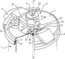
图1是表示用于在压力下蒸煮食物的本发明家用器具的局部切去的立体图,该家用器具处于解锁位置;Figure 1 is a perspective view, partly cut away, showing a domestic appliance for cooking food under pressure according to the invention, in an unlocked position;
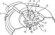
图2是详细地表示本发明的锁定/解锁装置的立体图,该锁定/解锁装置处于解锁位置;Figure 2 is a perspective view showing in detail the locking/unlocking device of the present invention, the locking/unlocking device being in an unlocked position;
图3是本发明的锁定/解锁装置的立体图,该锁定/解锁装置处于在锁定位置和解锁位置之间的中间位置;Figure 3 is a perspective view of the locking/unlocking device of the present invention in an intermediate position between the locked position and the unlocked position;
图4是本发明的锁定/解锁装置的详细立体图,该锁定/解锁装置处于将盖子锁定在钵上的位置,且器具处于压力下;Figure 4 is a detailed perspective view of the locking/unlocking device of the present invention in a position locking the lid on the bowl with the utensil under pressure;
图5是表示当锁定阀部件处于其泄漏的较低位置和当盖子锁定在钵上,且器具并不处于压力下时,在锁定阀部件、控制件和盖子之间的组件的剖视图;Figure 5 is a cross-sectional view showing the assembly between the locking valve member, the control and the lid when the locking valve member is in its leaky lower position and when the lid is locked on the bowl and the appliance is not under pressure;
图6是表示当锁定阀部件处于密封的较高位置和当盖子锁定在钵上,且器具处于压力下时,由锁定阀部件、控制件和盖子形成的组件的剖视图;以及Figure 6 is a cross-sectional view showing the assembly formed by the locking valve member, control and lid when the locking valve member is in the sealed higher position and when the lid is locked on the bowl and the appliance is under pressure; and
图7是表示当盖子处于在锁定位置和解锁位置之间的中间位置和当在器具内为非零相对压力时,由锁定阀部件、控制件和盖子形成的组件的剖视图。Figure 7 is a cross-sectional view showing the assembly formed by the locking valve member, control and lid when the lid is in an intermediate position between the locked and unlocked positions and when there is a non-zero relative pressure within the appliance.
具体实施方式Detailed ways
本发明的蒸煮器具设计成用于在家庭环境中在压力下蒸煮食物。The cooking appliance of the present invention is designed for cooking food under pressure in a domestic environment.
下面将参考图1至7介绍该器具。The appliance will be described below with reference to FIGS. 1 to 7 .
本发明的蒸煮器具包括:优选地为圆柱形的钵,该钵具有对称轴线Z—Z′;以及盖子2,该盖子2设计成通过密封垫圈3(例如,唇形密封件J)而以基本气密的方式安装在钵1上。The cooking appliance of the present invention comprises: a bowl, preferably cylindrical, having an axis of symmetry Z—Z'; It is installed on the bowl 1 in an airtight manner.
下文中,形容词“轴向的”是指对称轴线Z—Z′,它在器具正常操作时为基本垂直。Hereinafter, the adjective "axial" refers to the axis of symmetry Z—Z', which is substantially vertical in normal operation of the appliance.
通常,钵由金属材料(例如,不锈钢)制造,且它设有底部(未示出),该底部例如通过热冲压而固定在钵1上。Typically, the bowl is made of metallic material (eg stainless steel) and it is provided with a bottom (not shown) fixed to the bowl 1 eg by hot stamping.
有利地,钵1设置有用于抓起它的部件,例如手柄P,该部件优选地固定在钵1的壁上。Advantageously, the bowl 1 is provided with means for picking it up, such as a handle P, preferably fixed to the wall of the bowl 1 .
优选地,盖子2具有圆形外周,且它通过锁定/解锁装置3而锁定在钵1上。Preferably, the
本发明的锁定/解锁装置3包括两个优选地径向相对的夹头4,夹头4安装成可通过驱动臂5而在盖子2上在用于将盖子2锁定在钵1上的锁定位置和解锁位置之间径向运动,在该锁定位置,盖子固定在钵上,而在该解锁位置,盖子能够与钵分离。The locking/unlocking
当然,也可以设想采用这样的锁定/解锁装置,该锁定/解锁装置具有安装成可在盖子2上径向运动的单个夹头4。Of course, it is also conceivable to use a locking/unlocking device with a
在该变化实施例中(图中未示出),锁定/解锁装置有利地包括保持器,该保持器固定在钵上,并安装成与夹头径向相对,且盖子适于通过使它基本水平地滑入在保持器中的凹口内直到它垂直处于钵的上方而安装在该钵上。一旦处于该位置,就可以通过驱动夹头而锁定盖子。In this variant embodiment (not shown in the figures), the locking/unlocking means advantageously comprise a retainer fixed to the bowl and mounted diametrically opposite the collet, and the cover is adapted to pass by making it substantially Install on the bowl by sliding horizontally into the notch in the holder until it is vertically above the bowl. Once in this position, the lid can be locked by actuating the chuck.
夹头4有利地具有金属板形式,该金属板形成U形型面,适于夹在钵1的、向下弯的外周边缘6周围,这对本领域技术人员是公知的。The
本发明的锁定/解锁装置3还包括控制装置7,其用于使得与驱动臂5连接的夹头4沿径向运动,并使得夹头4运动至它们的锁定位置或它们的解锁位置。The inventive locking/
控制装置7有利地包括操作部件8(例如,按钮),该操作部件8适于特别是通过推入而运动,以使得夹头4移动。控制装置7还包括有利地为平板形式的控制件9,当使用者例如通过在操作部件8上进行推动或拉动而致动该操作部件8时,该控制件适于产生运动。The control means 7 advantageously comprise an operating part 8 (for example a button) adapted to be moved, in particular by pushing in, in order to move the
根据本发明,控制件9安装成可在盖子2上平移运动,且它直接与驱动臂5配合,这样,控制件9的平移运动使得驱动臂5以线性方式沿轴线进行径向运动(该轴线优选地垂直于控制件9的运动方向)。驱动臂5有利地被引导以使得它们以严格线性方式径向运动。According to the invention, the
优选地,由按钮形成的操作部件8固定在控制件9上。因此,当使用者按压该按钮时,使用者直接使得控制件9平移运动,从而使得夹头4运动,然后,驱动臂5被控制件9朝向器具的外周推开。Preferably, the operating part 8 formed by a button is fixed on the
因此,根据控制件9运动的方向,所述控制件将驱动臂5推向器具的中心,从而使得夹头4被锁定,或者将驱动臂5朝向外周推开,从而解锁夹头4。Thus, depending on the direction in which the
根据本发明,盖子2设置有至少一个孔10A,其有利地使得插入件30能够通过夹住而被安装,该插入件优选地由弹性体制成,并设置有通道30A,锁定阀部件10安装在该通道30A中,从而当器具内有足够压力时在泄漏的较低位置(如图5所示)和密封的较高位置(如图6所示)之间自由地轴向滑动。如本领域技术人员所公知的,锁定阀部件10可以由叉头钉或“枢轴”来构成,它的一个作用是提供关于器具内的压力的可视信息。According to the invention, the
在其较高位置时,锁定阀部件10通过布置在轴环12上的垫圈11而实现蒸汽密封功能,该垫圈优选地由弹性体制成,并形成锁定阀部件10的径向最外侧底部(图6)。In its upper position, the locking
因此,当锁定阀部件10处于其较高位置时,密封垫圈11在插入件30的底壁和轴环12之间被压平。Thus, the sealing washer 11 is compressed between the bottom wall of the insert 30 and the collar 12 when the locking
如本领域技术人员所公知的,本发明的家用蒸煮器具还可以包括调节阀部件13,该调节阀部件13设计成将容器内部的压力保持为基本恒定的预定压力(称为“工作压力”)。As known to those skilled in the art, the domestic cooking appliance of the present invention may also include a regulating
根据本发明,控制件9设置有孔14,该孔14相对于锁定阀部件10布置成以使得,当夹头4处于锁定位置时,锁定装置10能自由地处于其在所述孔14中的较高位置,从而将控制件9锁定在适当的位置(图4)。According to the invention, the
因此,本发明的器具有特别紧凑和简单的设计,这使它简单、并可靠地保证夹头4处于合适位置,且保证盖子2完全和安全地在钵1上关闭。Thus, the appliance of the invention has a particularly compact and simple design, which makes it simple and reliable to ensure that the
只要容器内的压力超过预定值(例如,大约0.5千帕(kPa)),锁定阀部件10就保持在较高位置,并使控制件9保持固定,从而将驱动臂5和相应夹头4保持在它们的锁定位置。As long as the pressure in the container exceeds a predetermined value (for example, about 0.5 kilopascals (kPa)), the locking
因此,本发明的器具通过单个控制件9不仅能够使得夹头4运动,还可以防止在并不满足所有安全条件时打开盖子2。Thus, the appliance of the invention not only enables movement of the
有利地,孔14和锁定阀10彼此相对成形为使得当夹头4处于解锁位置(如图1和2所示)或处于在锁定位置和解锁位置之间的中间位置(如图3所示)时防止阀部件10进入较高位置,从而防止当所述器具未锁定时在器具内部压力增大。Advantageously, the
因此,有利地,锁定阀部件10包括主体15、颈部16和头部17,颈部16的截面尺寸小于主体5和头部17的截面尺寸。Thus, advantageously, the locking
以特别有利的方式,孔14设置有引导通路18,如图2至4所示。有利地,引导通路18的宽度明显大于颈部16的宽度,从而当锁定阀部件10处于较低位置时适于在所述颈部16周围滑动,从而允许控制件9能够在锁定位置和解锁位置(图2和3)之间运动。In a particularly advantageous manner, the
相反,优选地引导通路18的宽度明显小于主体15的宽度,从而当夹头4处于解锁位置或处于在锁定位置和解锁位置之间的中间位置(图2和3)时,防止阀部件10进入较高位置。Instead, the width of the
然后,有利地,控制件9形成对于阀部件10的主体15的抵靠(图7)。这样,阀部件10由于不能进入较高位置而允许蒸汽泄漏,从而防止在器具内部的相对压力超过预定值,例如大约4kPa。Advantageously, the
以特别有利的方式,引导通路18优选地沿轴线(控制件9沿该轴线运动)延伸,也就是平行于箭头F1和F2(图1)的轴线,即基本垂直于驱动臂5运动的轴线,从而使得所述控制件9平移运动。In a particularly advantageous manner, the
有利地,器具包括帽40,该帽40设置有凹口41,该凹口41在其底端局部由肩部42关闭,该肩部42形成对于头部17的抵靠(图5至7)。Advantageously, the appliance comprises a cap 40 provided with a notch 41 partially closed at its bottom end by a shoulder 42 forming an abutment against the head 17 ( FIGS. 5 to 7 ) .
有利地,锁定阀部件10安装成悬在帽40上,这样,在其泄漏的较低位置,它将通过头部17抵靠肩部42(图5)。Advantageously, the locking
以特别有利的方式,孔14具有局部较宽部分19(图1至3和图5至7),该较宽部分19布置成使得,在锁定位置,锁定阀部件10能够在所述局部较宽部分19中处于其较高位置,从而将控制件9锁定在适当的位置,如图6所示。In a particularly advantageous manner, the
因此,每当器具容器内的相对压力(处于锁定位置)超过预定值(例如,大约1.5kPa)时,锁定阀部件10就占据局部较宽部分19的空闲空间,并形成对于控制件9的抵靠,从而防止所述控制件运动。这时,使用者不再能够打开该器具。Thus, whenever the relative pressure in the appliance container (in the locked position) exceeds a predetermined value (for example, about 1.5 kPa), the locking
以特别有利的方式,控制件9的运动(当能够进行该运动时)使得驱动臂5和相关联的夹头4通过驱动装置而径向运动,该驱动装置布置(即,设置或安装)在控制件9上,并用于与固定在驱动臂5上或与该驱动臂5成一体的相应接合装置配合。In a particularly advantageous manner, the movement of the control member 9 (when this movement is possible) causes the
有利地,该驱动装置布置成这样,即,控制件9沿与驱动臂5运动的轴线基本垂直的轴线的运动而使得所述臂沿径向运动。Advantageously, the drive means are arranged such that movement of the
有利地,驱动装置由两个狭槽20形成,这两个狭槽20优选地设置成穿过形成控制件9的板的整个厚度,且它们优选地关于轴线Z—Z′径向相对。Advantageously, the drive means are formed by two
有利地,接合装置由两个凸耳21形成,这两个凸耳21布置在驱动臂5上,并优选地在该驱动臂5的内端,即位于轴线Z—Z′附近的端部。Advantageously, the engagement means are formed by two
当然,当器具包括单个夹头4时,驱动装置优选地由单个狭槽20形成,该狭槽20用于与布置在单个驱动臂5上的单个凸耳21配合。Of course, when the appliance comprises a
当使用者的手可接近的操作部件8(特别是按钮)通过拉动或推动而被致动时,凸耳21在平移运动的控制件9的作用下在狭槽20内滑动,从而使得驱动臂5沿径向运动。因此,凸耳21不能在狭槽20内自由运动,而是服从于控制件9的运动。When the operating part 8 (in particular the button) accessible by the user's hand is actuated by pulling or pushing, the
为了使得使用者可接近操作部件8,所述部件优选地例如通过垫片元件22而安装在控制件9的上方(图4)。In order to make the operating part 8 accessible to the user, said part is preferably mounted above the
以特别有利的方式,狭槽20沿相对于夹头4运动的径向轴线明显倾斜的轴线而纵向延伸(图1)。In a particularly advantageous manner, the
狭槽20的端部形成对于凸耳21的抵靠,从而限制它们的行程,并因此限制驱动臂5和相应夹头4的行程。The ends of the
有利地,各狭槽20在其端部设置有停止区域(setback zone)23、24,各停止区域23、24用于容纳处于相应的锁定位置和解锁位置之一的凸耳21。这些器具的设计(特别是首先在控制件9和凸耳21之间以及其次在锁定阀部件10之间的直接配合)使得系统能够在器具处于压力下时承受非常大的打开力。Advantageously, each
有利地,驱动臂通过弹性返回装置而被持续往回推向锁定位置,该弹性返回装置例如由插设在两个支柱之间的弹簧(图中未示出)构成,这两个支柱固定在相应驱动臂上或与该驱动臂成一体。Advantageously, the drive arm is continuously pushed back towards the locked position by means of elastic return means, for example constituted by a spring (not shown) interposed between two struts fixed in the on or integral with the corresponding drive arm.
在专利申请WO 96/01069中详细地描述了这种结构,因此下面将不再更详细地介绍。This structure is described in detail in patent application WO 96/01069 and therefore will not be described in more detail below.
有利地,与控制件9相关联的操作部件8能够使驱动臂5有效地沿径向向外方向(即,沿对应于夹头4逐渐分开以便到达它们的解锁端位置的方向)运动,或者有效地沿径向向内方向(即,沿夹头4朝向它们的锁定位置运动的方向)运动,且这能够只通过推动或拉动操作部件8而实现。Advantageously, the operating member 8 associated with the
如专利申请WO 96/01069中所述,还可以使用两个不同控制部件来锁定和解锁盖子。As described in patent application WO 96/01069, it is also possible to use two different control parts to lock and unlock the lid.
因此,操作部件8例如可以只用于使驱动臂5径向向外运动,而安装成在旋钮51(该旋钮51固定在盖子2上)中轴向弹性运动的控制按钮52可以通过轴向推动控制按钮52而使驱动臂15沿径向向内的方向运动。Thus, for example, the operating part 8 can only be used to move the
在专利申请WO 96/01069中详细地描述了控制按钮52和相关联装置的操作。The operation of the
因此,本发明的压力蒸煮器具的优点是,只有处于一个位置时能够在它内部增大压力,该位置对应于盖子锁定在钵上的锁定端位置。Thus, the pressure cooker of the present invention has the advantage that pressure can be built up inside it only in one position, which corresponds to the locked end position of the lid locked on the bowl.
下面将介绍用于在压力下蒸煮食物的本发明的家用器具的操作和使用模式。The mode of operation and use of the household appliance of the invention for cooking food under pressure will be described below.
为了将盖子2布置在钵1上,必须打开夹头4,并通过径向推动操作部件8而致动该操作部件,从而能够使控制件沿由箭头F2表示的方向滑动,从而径向向外驱动布置在相应狭槽20中的各凸耳21。In order to place the
因此,逐渐运动的操作部件8能够使得驱动臂5和相应夹头4同时逐渐地运动分开。一旦各凸耳21位于停止区域24中,该运动就结束(图4)。这样,通过凸耳21抵靠狭槽20端部来确定夹头4的间开极限位置。在这样到达的端部位置,盖子2可以位于钵1的中心(图1)。Thus, the gradually moving operating member 8 enables the simultaneous progressive movement of the
通过拉动操作部件8或者通过用手在控制按钮52(如果器具设置有该按钮)上施加压力,将对应于夹头到达它们的锁定位置而使器具关闭。By pulling the operating part 8 or by applying pressure by hand on the control button 52 (if the appliance is provided with such a button), the appliance will be closed corresponding to the jaws reaching their locked position.
不管使用什么控制部件,操作它都将使得控制件9沿箭头F1所示方向平移运动,该平移运动首先使得凸耳21离开停止区域24,随后使得各凸耳沿径向向心方向运动,从而使得夹头4彼此相向运动,直到它们到达它们的锁定位置(图4)。Regardless of the control part used, operating it will cause a translational movement of the
也可以至少部分地通过布置在两个驱动臂5之间的返回弹簧而实现返回到锁定位置。The return to the locked position can also be achieved at least partly by means of a return spring arranged between the two
在关闭结束时,锁定/解锁装置3有利地发出可听见的声音,以通知使用者已经适当地锁定了器具。At the end of closing, the locking/unlocking
凸出至旋纽51外部的按钮(形成操作部件8)的位置也通知使用者是否已经正确地锁定了器具。The position of the button (forming the operating part 8 ) protruding to the outside of the
当以基本密封的方式锁定器具时,在外壳内部的压力会增加,并使得锁定阀部件10通过孔14(准确地是通过局部较宽部分19)而升高至其较高位置。When locking the appliance in a substantially sealed manner, the pressure inside the housing increases and causes the locking
因此,与局部较宽部分19接合的锁定阀部件10可以同时首先将控制件或板9锁定在适当的位置,其次可以将驱动臂5和相应夹头4锁定在适当的位置。Thus, the locking
这样,本发明的锁定/解锁装置3能够完全安全地增大压力,这是因为只有当驱动臂5及由此夹头4处于锁定端位置时,锁定阀部件10才能够通过锁定孔14。In this way, the inventive locking/unlocking
通过与锁定阀部件10配合,使用单个控制件9能够使得夹头4运动并可以进行锁定,这首先防止了形成不希望的游隙,特别是当多个部件配合在一起时,其次减小了夹头4歪斜引导的危险。By cooperating with the locking
而且,如果由于任何原因使得器具不能适当地关闭,则在容器内部的相对压力不能超过预定值(例如,大约4kPa),这是因为孔14和锁定阀部件10成形为这样,即,当盖子2没有正确锁定在钵1上时,所述锁定阀部件不能进入密封的较高位置。Also, if for any reason the appliance does not close properly, the relative pressure inside the container cannot exceed a predetermined value (e.g. about 4kPa) because the
特别是,每当夹头4处于解锁位置或处于在锁定位置和解锁位置之间的中间位置时,锁定阀部件10必然定位成与引导通路18对齐,从而相对于局部较宽部分19偏离,因此,在外壳内部的压力作用下,阀部件10升高,直到主体15抵靠控制件9,从而允许通过通道30A进行泄漏。In particular, whenever the
当器具被正确关闭并锁定时,只要钵内的相对压力超过大约1.5kPa,则就不能打开该器具。When the appliance is properly closed and locked, the appliance cannot be opened as long as the relative pressure inside the bowl exceeds about 1.5 kPa.
在蒸煮结束时,只要钵内的相对压力大于0.5kPa,使用者就不能打开器具。当器具内部的相对压力等于或小于0.5kPa时,锁定阀10返回其较低位置,并通过使控制件9平移运动而允许盖子2再次打开,这时引导通路18适于在阀部件10的颈部16周围滑动。At the end of cooking, the user cannot open the appliance as long as the relative pressure in the bowl is greater than 0.5kPa. When the relative pressure inside the appliance is equal to or less than 0.5 kPa, the locking
这样,使用者能够使操作部件8沿箭头F2所示的方向运动,以便使得夹头4以线性和离心的方式沿径向运动,从而能够取下盖子2。In this way, the user can move the operating member 8 in the direction indicated by the arrow F2 in order to move the
当然,只是为了进行说明而仅以示例的方式给出上述相对压力值。Of course, the above relative pressure values are given by way of example only for the sake of illustration.
工业实用性Industrial Applicability
本发明的工业用途在于家用压力蒸煮器具(特别是压力锅)的设计和制造。The industrial application of the invention lies in the design and manufacture of domestic pressure cooking appliances, especially pressure cookers.
Claims (10)
Translated fromChineseApplications Claiming Priority (2)
| Application Number | Priority Date | Filing Date | Title |
|---|---|---|---|
| FR0315241 | 2003-12-23 | ||
| FR0315241AFR2863849B1 (en) | 2003-12-23 | 2003-12-23 | DOMESTIC PRESSURIZED FOOD COOKING APPARATUS WITH IMPROVED LATCHING DEVICE |
Publications (2)
| Publication Number | Publication Date |
|---|---|
| CN1705449A CN1705449A (en) | 2005-12-07 |
| CN100522018Ctrue CN100522018C (en) | 2009-08-05 |
Family
ID=34531331
Family Applications (1)
| Application Number | Title | Priority Date | Filing Date |
|---|---|---|---|
| CNB2004800012573AExpired - Fee RelatedCN100522018C (en) | 2003-12-23 | 2004-12-22 | Domestic pressure cooking appliance with improved locking device |
Country Status (7)
| Country | Link |
|---|---|
| EP (1) | EP1547497B1 (en) |
| CN (1) | CN100522018C (en) |
| AT (1) | ATE363224T1 (en) |
| DE (1) | DE602004006704T2 (en) |
| ES (1) | ES2288246T3 (en) |
| FR (1) | FR2863849B1 (en) |
| WO (1) | WO2005063088A1 (en) |
Cited By (11)
| Publication number | Priority date | Publication date | Assignee | Title |
|---|---|---|---|---|
| US10390656B2 (en) | 2017-08-09 | 2019-08-27 | Sharkninja Operating Llc | Cooking device and components thereof |
| USD873602S1 (en) | 2018-08-09 | 2020-01-28 | Sharkninja Operating Llc | Lid part of a food preparation device |
| USD874211S1 (en) | 2018-08-09 | 2020-02-04 | Sharkninja Operating Llc | Food preparation device and parts thereof |
| USD903413S1 (en) | 2018-08-09 | 2020-12-01 | Sharkninja Operating Llc | Cooking basket |
| USD914436S1 (en) | 2018-06-19 | 2021-03-30 | Sharkninja Operating Llc | Air diffuser with food preparation pot |
| USD918654S1 (en) | 2019-06-06 | 2021-05-11 | Sharkninja Operating Llc | Grill plate |
| US11033146B2 (en) | 2019-02-25 | 2021-06-15 | Sharkninja Operating Llc | Cooking device and components thereof |
| USD922126S1 (en) | 2019-06-06 | 2021-06-15 | Sharkninja Operating Llc | User interface for a food preparation device |
| US11134808B2 (en) | 2020-03-30 | 2021-10-05 | Sharkninja Operating Llc | Cooking device and components thereof |
| USD932833S1 (en) | 2018-08-09 | 2021-10-12 | Sharkninja Operating Llc | Reversible cooking rack |
| US11751710B2 (en) | 2019-02-25 | 2023-09-12 | Sharkninja Operating Llc | Guard for cooking system |
Families Citing this family (10)
| Publication number | Priority date | Publication date | Assignee | Title |
|---|---|---|---|---|
| DE102008009247B4 (en)* | 2008-02-07 | 2015-04-16 | Rieber Gmbh & Co. Kg | Lid for food containers in Gastronorm format |
| FR2940602B1 (en) | 2008-12-30 | 2013-03-29 | Seb Sa | PRESSURIZED COOKING APPARATUS WITH INTERDEPENDENT CONTROL ORGANS |
| FR2940603B1 (en) | 2008-12-30 | 2011-01-28 | Seb Sa | PRESSURIZED COOKING APPARATUS PROVIDED WITH AN ASYMMETRICALLY OPERATED LOCKING / UNLOCKING CONTROL MEMBER |
| FR2940601B1 (en) | 2008-12-30 | 2012-07-13 | Seb Sa | PRESSURIZED COOKING APPARATUS WITH BI-FUNCTIONAL LOCKING / UNLOCKING CONTROL MEMBER |
| FR2965708B1 (en) | 2010-10-06 | 2012-12-07 | Seb Sa | PRESSURE COOKING APPARATUS WITH DEBRAYABLE CONTROL MEMBER |
| CN102415812A (en)* | 2011-10-19 | 2012-04-18 | 浙江苏泊尔股份有限公司 | Device for opening and closing cover of kitchenware |
| FR2998152B1 (en)* | 2012-11-16 | 2017-11-24 | Seb Sa | PRESSURIZED FOOD COOKING APPARATUS HAVING AN IMPROVED ORDERING MEMBER |
| FR2998150B1 (en)* | 2012-11-16 | 2015-02-06 | Seb Sa | PRESSURIZED FOOD COOKING APPARATUS WITH ENHANCED UNLOCKING CONTROL |
| CN106073480B (en)* | 2016-08-09 | 2019-06-04 | 新兴县先丰不锈钢制品有限公司 | Button folding can found lid micropressure boiler |
| CN106073482B (en)* | 2016-08-30 | 2018-08-10 | 新兴县先丰不锈钢制品有限公司 | Multi-funcltional pot with vent valve |
Family Cites Families (4)
| Publication number | Priority date | Publication date | Assignee | Title |
|---|---|---|---|---|
| BE806483A (en)* | 1973-10-25 | 1974-04-25 | Tomado Nv | AUTOMATIC LID PROTECTION FOR PRESSURE VESSEL |
| FR2722078B1 (en) | 1994-07-06 | 1996-08-30 | Seb Sa | DEVICE FOR CONTROLLING THE OPENING AND CLOSING OF LOCKING JAWS FOR A PRESSURE CONTAINER |
| FR2722077B1 (en) | 1994-07-06 | 1996-08-23 | Seb Sa | JAW LOCKING / UNLOCKING DEVICE OF A LID ON A TANK |
| DE20201624U1 (en)* | 2002-02-01 | 2003-06-18 | Synkrona Ag, Stans | Closing device for a container |
- 2003
- 2003-12-23FRFR0315241Apatent/FR2863849B1/ennot_activeExpired - Fee Related
- 2004
- 2004-12-22CNCNB2004800012573Apatent/CN100522018C/ennot_activeExpired - Fee Related
- 2004-12-22DEDE602004006704Tpatent/DE602004006704T2/ennot_activeExpired - Lifetime
- 2004-12-22EPEP04356205Apatent/EP1547497B1/ennot_activeExpired - Lifetime
- 2004-12-22WOPCT/FR2004/003343patent/WO2005063088A1/enactiveApplication Filing
- 2004-12-22ESES04356205Tpatent/ES2288246T3/ennot_activeExpired - Lifetime
- 2004-12-22ATAT04356205Tpatent/ATE363224T1/ennot_activeIP Right Cessation
Cited By (71)
| Publication number | Priority date | Publication date | Assignee | Title |
|---|---|---|---|---|
| US11399657B2 (en) | 2017-08-09 | 2022-08-02 | Sharkninja Operating Llc | Cooking device and components thereof |
| US11445856B2 (en) | 2017-08-09 | 2022-09-20 | Sharkninja Operating Llc | Cooking device and components thereof |
| US10405698B2 (en) | 2017-08-09 | 2019-09-10 | Sharkninja Operating Llc | Cooking device and components thereof |
| US10413121B2 (en) | 2017-08-09 | 2019-09-17 | Sharkninja Operating Llc | Cooking device and components thereof |
| US10413122B2 (en) | 2017-08-09 | 2019-09-17 | Sharkninja Operating Llc | Cooking device and components thereof |
| US10485378B2 (en) | 2017-08-09 | 2019-11-26 | Sharkninja Operating Llc | Cooking device and components thereof |
| US11889950B2 (en) | 2017-08-09 | 2024-02-06 | Sharkninja Operating Llc | Cooking device and components thereof |
| US11759049B2 (en) | 2017-08-09 | 2023-09-19 | Sharkninja Operating Llc | Cooking device and components thereof |
| US11759048B2 (en) | 2017-08-09 | 2023-09-19 | Sharkninja Operating Llc | Cooking device and components thereof |
| US11627834B2 (en) | 2017-08-09 | 2023-04-18 | Sharkninja Operating Llc | Cooking system for cooking food |
| US11547243B2 (en) | 2017-08-09 | 2023-01-10 | Sharkninja Operating Llc | Cooking device and components thereof |
| US11547242B2 (en) | 2017-08-09 | 2023-01-10 | Sharkninja Operating Llc | Cooking device and components thereof |
| US10390656B2 (en) | 2017-08-09 | 2019-08-27 | Sharkninja Operating Llc | Cooking device and components thereof |
| US11363910B2 (en) | 2017-08-09 | 2022-06-21 | Sharkninja Operating Llc | Cooking device and components thereof |
| US10646070B2 (en) | 2017-08-09 | 2020-05-12 | Sharkninja Operating Llc | Cooking device and components thereof |
| US10653270B2 (en) | 2017-08-09 | 2020-05-19 | Sharkninja Operating Llc | Cooking device and components thereof |
| US10660472B2 (en) | 2017-08-09 | 2020-05-26 | Sharkninja Operating Llc | Cooking device and components thereof |
| US10674868B2 (en) | 2017-08-09 | 2020-06-09 | Sharkninja Operating Llc | Cooking device and components thereof |
| US10682011B2 (en) | 2017-08-09 | 2020-06-16 | Sharkninja Operating Llc | Cooking device and components thereof |
| US11304561B2 (en) | 2017-08-09 | 2022-04-19 | Sharkninja Operating Llc | Cooking device and components thereof |
| US11278151B2 (en) | 2017-08-09 | 2022-03-22 | Sharkninja Operating Llc | Cooking device and components thereof |
| US11266267B2 (en) | 2017-08-09 | 2022-03-08 | Sharkninja Operating Llc | Cooking device and components thereof |
| US11266268B2 (en) | 2017-08-09 | 2022-03-08 | Sharkninja Operating Llc | Cooking device and components thereof |
| US10405697B2 (en) | 2017-08-09 | 2019-09-10 | Sharkninja Operating Llc | Cooking device and components thereof |
| US11109710B2 (en) | 2017-08-09 | 2021-09-07 | Sharkninja Operating Llc | Cooking device and components thereof |
| US11089902B2 (en) | 2017-08-09 | 2021-08-17 | Sharkninja Operating Llc | Cooking device and components thereof |
| US11089903B2 (en) | 2017-08-09 | 2021-08-17 | Sharkninja Operating Llc | Cooking device and components thereof |
| USD914447S1 (en) | 2018-06-19 | 2021-03-30 | Sharkninja Operating Llc | Air diffuser |
| USD914436S1 (en) | 2018-06-19 | 2021-03-30 | Sharkninja Operating Llc | Air diffuser with food preparation pot |
| USD948938S1 (en) | 2018-06-19 | 2022-04-19 | Sharkninja Operating Llc | Air diffuser |
| USD883016S1 (en) | 2018-08-09 | 2020-05-05 | Sharkninja Operating Llc | Food preparation device and parts thereof |
| USD883015S1 (en) | 2018-08-09 | 2020-05-05 | Sharkninja Operating Llc | Food preparation device and parts thereof |
| USD931680S1 (en) | 2018-08-09 | 2021-09-28 | Sharkninja Operating Llc | Cooking basket |
| USD876160S1 (en) | 2018-08-09 | 2020-02-25 | Sharkninja Operating Llc | Food preparation device and parts thereof |
| USD920732S1 (en) | 2018-08-09 | 2021-06-01 | Sharkninja Operating Llc | Food preparation device |
| USD929793S1 (en) | 2018-08-09 | 2021-09-07 | Sharkninja Operating Llc | Food preparation device |
| USD876874S1 (en) | 2018-08-09 | 2020-03-03 | Sharkninja Operating Llc | User interface for a food preparation device |
| USD932833S1 (en) | 2018-08-09 | 2021-10-12 | Sharkninja Operating Llc | Reversible cooking rack |
| USD874211S1 (en) | 2018-08-09 | 2020-02-04 | Sharkninja Operating Llc | Food preparation device and parts thereof |
| USD883017S1 (en) | 2018-08-09 | 2020-05-05 | Sharkninja Operating Llc | User interface for food preparation device |
| USD883014S1 (en) | 2018-08-09 | 2020-05-05 | Sharkninja Operating Llc | Food preparation device |
| USD929173S1 (en) | 2018-08-09 | 2021-08-31 | Sharkninja Operating Llc | Food preparation device |
| USD940503S1 (en) | 2018-08-09 | 2022-01-11 | Sharkninja Operating Llc | Cooking basket |
| USD941090S1 (en) | 2018-08-09 | 2022-01-18 | Sharkninja Operating Llc | Cooking basket |
| USD873602S1 (en) | 2018-08-09 | 2020-01-28 | Sharkninja Operating Llc | Lid part of a food preparation device |
| USD903414S1 (en) | 2018-08-09 | 2020-12-01 | Sharkninja Operating Llc | Cooking basket |
| USD903415S1 (en) | 2018-08-09 | 2020-12-01 | Sharkninja Operating Llc | Cooking basket |
| USD903413S1 (en) | 2018-08-09 | 2020-12-01 | Sharkninja Operating Llc | Cooking basket |
| USD929794S1 (en) | 2018-08-09 | 2021-09-07 | Sharkninja Operating Llc | Food preparation device |
| USD935259S1 (en) | 2018-08-09 | 2021-11-09 | Sharkninja Operating Llc | Food preparation device |
| USD934027S1 (en) | 2018-08-09 | 2021-10-26 | Sharkninja Operating Llc | Reversible cooking rack |
| US11147415B2 (en) | 2019-02-25 | 2021-10-19 | Sharkninja Operating Llc | Cooking device and components thereof |
| US11751710B2 (en) | 2019-02-25 | 2023-09-12 | Sharkninja Operating Llc | Guard for cooking system |
| US12226039B2 (en) | 2019-02-25 | 2025-02-18 | Sharkninja Operating Llc | Guard for cooking system |
| US11051654B2 (en) | 2019-02-25 | 2021-07-06 | Sharkninja Operating Llc | Cooking device and components thereof |
| US11832761B2 (en) | 2019-02-25 | 2023-12-05 | Sharkninja Operating Llc | Cooking device and components thereof |
| US11363911B2 (en) | 2019-02-25 | 2022-06-21 | Sharkninja Operating Llc | Cooking device and components thereof |
| US11766152B2 (en) | 2019-02-25 | 2023-09-26 | Sharkninja Operating Llc | Cooking device and components thereof |
| US11033146B2 (en) | 2019-02-25 | 2021-06-15 | Sharkninja Operating Llc | Cooking device and components thereof |
| US11751722B2 (en) | 2019-02-25 | 2023-09-12 | Sharkninja Operating Llc | Cooking device and components thereof |
| USD922126S1 (en) | 2019-06-06 | 2021-06-15 | Sharkninja Operating Llc | User interface for a food preparation device |
| USD918654S1 (en) | 2019-06-06 | 2021-05-11 | Sharkninja Operating Llc | Grill plate |
| USD982375S1 (en) | 2019-06-06 | 2023-04-04 | Sharkninja Operating Llc | Food preparation device |
| USD934631S1 (en) | 2019-06-06 | 2021-11-02 | Sharkninja Operating Llc | Grill plate |
| USD1015798S1 (en) | 2019-06-06 | 2024-02-27 | Sharkninja Operating Llc | Food preparation device |
| USD1049746S1 (en) | 2019-06-06 | 2024-11-05 | Sharkninja Operating Llc | Food preparation device |
| USD1054771S1 (en) | 2019-06-06 | 2024-12-24 | Sharkninja Operating Llc | Food preparation device |
| US11678765B2 (en) | 2020-03-30 | 2023-06-20 | Sharkninja Operating Llc | Cooking device and components thereof |
| US11647861B2 (en) | 2020-03-30 | 2023-05-16 | Sharkninja Operating Llc | Cooking device and components thereof |
| US11969118B2 (en) | 2020-03-30 | 2024-04-30 | Sharkninja Operating Llc | Cooking device and components thereof |
| US11134808B2 (en) | 2020-03-30 | 2021-10-05 | Sharkninja Operating Llc | Cooking device and components thereof |
Also Published As
| Publication number | Publication date |
|---|---|
| JP2005177514A (en) | 2005-07-07 |
| DE602004006704D1 (en) | 2007-07-12 |
| ATE363224T1 (en) | 2007-06-15 |
| JP3970879B2 (en) | 2007-09-05 |
| FR2863849A1 (en) | 2005-06-24 |
| CN1705449A (en) | 2005-12-07 |
| WO2005063088A1 (en) | 2005-07-14 |
| FR2863849B1 (en) | 2006-11-10 |
| EP1547497B1 (en) | 2007-05-30 |
| ES2288246T3 (en) | 2008-01-01 |
| EP1547497A1 (en) | 2005-06-29 |
| DE602004006704T2 (en) | 2008-01-24 |
Similar Documents
| Publication | Publication Date | Title |
|---|---|---|
| CN100522018C (en) | Domestic pressure cooking appliance with improved locking device | |
| RU2126224C1 (en) | Apparatus for controlling opening and closing of locking clamps for vessels, preferably, pressure vessels, and pressure vessel provided with such apparatus | |
| JP4235669B2 (en) | Pressure cooker with a single control member for decompression and locking / unlocking | |
| JP6517224B2 (en) | Microwave pressure cooker | |
| CN108294613B (en) | Snap-on pressure cooker and movable lock | |
| US8546731B2 (en) | Electrical appliance for cooking food | |
| US8247751B2 (en) | Microwave pressure cooker | |
| JP6297779B2 (en) | Vertically depressible gasket and pressure cooker with such a gasket | |
| KR102472981B1 (en) | A bayonet-fitting pressure cooker provided with a vessel handle | |
| US8205543B2 (en) | Pressure cooker equipped with a screen | |
| AU2014319872B2 (en) | Pressure cooker | |
| EP3308685A1 (en) | Cooking appliance | |
| KR102452939B1 (en) | Bayonet pressure cooker with interlockable bowl and lid handles | |
| CN100531628C (en) | Pressure cooker with improved safety system | |
| CN102753066A (en) | Devices that simplify operation | |
| KR101690687B1 (en) | Portable Cooker | |
| JP6289414B2 (en) | Cooking device | |
| KR101433097B1 (en) | Vacuum pot | |
| JP3970879B6 (en) | Household device for cooking food under pressure with improved locking device | |
| WO2017145414A1 (en) | Rice cooker | |
| CN108338656B (en) | Cooking utensil | |
| JP2015100624A (en) | Cooker | |
| CN212089212U (en) | Cooking utensil | |
| JP2017153506A (en) | rice cooker | |
| JP2005152242A (en) | Coffee brewer, and coffee brewing method |
Legal Events
| Date | Code | Title | Description |
|---|---|---|---|
| C06 | Publication | ||
| PB01 | Publication | ||
| C10 | Entry into substantive examination | ||
| SE01 | Entry into force of request for substantive examination | ||
| C14 | Grant of patent or utility model | ||
| GR01 | Patent grant | ||
| C56 | Change in the name or address of the patentee | Owner name:SEB S.A. Free format text:FORMER NAME: SEB S. A. | |
| CP01 | Change in the name or title of a patent holder | Address after:French Ekri Patentee after:SEB S.A. Address before:French Ekri Patentee before:SEB S.A. | |
| EE01 | Entry into force of recordation of patent licensing contract | ||
| EE01 | Entry into force of recordation of patent licensing contract | Application publication date:20051207 Assignee:Zhejiang Supor Co.,Ltd. Assignor:SEB S.A. Contract record no.:2014990000057 Denomination of invention:Domestic pressure cooking appliance with improved locking device Granted publication date:20090805 License type:Common License Record date:20140127 | |
| CF01 | Termination of patent right due to non-payment of annual fee | ||
| CF01 | Termination of patent right due to non-payment of annual fee | Granted publication date:20090805 Termination date:20211222 |