CN100519202C - Ink supply tube fixing mechanism - Google Patents
Ink supply tube fixing mechanismDownload PDFInfo
- Publication number
- CN100519202C CN100519202CCNB200610121528XACN200610121528ACN100519202CCN 100519202 CCN100519202 CCN 100519202CCN B200610121528X ACNB200610121528X ACN B200610121528XACN 200610121528 ACN200610121528 ACN 200610121528ACN 100519202 CCN100519202 CCN 100519202C
- Authority
- CN
- China
- Prior art keywords
- ink
- ink supply
- fixing mechanism
- supply tube
- tube fixing
- Prior art date
- Legal status (The legal status is an assumption and is not a legal conclusion. Google has not performed a legal analysis and makes no representation as to the accuracy of the status listed.)
- Expired - Fee Related
Links
Images


Landscapes
- Ink Jet (AREA)
Abstract
Description
Translated fromChinese技术领域technical field
本发明有关一种供墨管固定机构,尤指一种适用于使用连续供墨系统的打印输出装置的供墨管固定机构。The invention relates to an ink supply tube fixing mechanism, in particular to an ink supply tube fixing mechanism suitable for a printing output device using a continuous ink supply system.
背景技术Background technique
随着技术发展与需求成长,目前的打印输出装置不仅可打印各式文件及表单,还可提供文宣资料及数字相片的输出,俨然成为日常生活及工作中不可或缺的输出设备。不过,现有打印输出装置为了应付大量且多样化的打印工作,将使得墨水匣中的墨水快速地消耗,再加上墨水匣的储墨量有限,因此很快就必须更换新的墨水匣,如此一来势必要中断打印工作,对于需要大量打印的使用者来说十分不方便,且长期下来耗材成本过高,也不符合环保概念。With the development of technology and the growth of demand, the current printing output device can not only print various documents and forms, but also provide the output of promotional materials and digital photos, and it has become an indispensable output device in daily life and work. However, in order to cope with a large number of and diversified printing jobs, the existing printing output device will cause the ink in the ink cartridge to be consumed quickly, and the ink storage capacity of the ink cartridge is limited, so a new ink cartridge must be replaced soon. This will inevitably interrupt the printing work, which is very inconvenient for users who need to print a lot, and the cost of consumables will be too high in the long run, and it does not conform to the concept of environmental protection.
有鉴于此,一种连续供墨系统便应运而生,其是通过一条或数条供墨管,将墨水自大容量的外墨盒引导至打印输出装置的墨水匣中,使墨水匣可利用喷墨头不断喷出墨水至喷墨媒体例如:纸张上的同时,该墨水匣也不断利用供墨管自外墨盒吸入等量的墨水以补充平衡,进而达到连续供墨的目的。In view of this, a continuous ink supply system has emerged as the times require, which guides the ink from the large-capacity external ink tank to the ink cartridge of the printout device through one or several ink supply tubes, so that the ink cartridge can be used for spraying. While the ink head continuously ejects ink to the inkjet media such as paper, the ink cartridge also continuously uses the ink supply tube to inhale an equal amount of ink from the outer ink box to replenish the balance, thereby achieving the purpose of continuous ink supply.
然而,在进行打印工作时喷墨头及墨水匣会来回反复地快速移动,进而会牵动与其连接的供墨管,此时若供墨管长度过长、没有固定供墨管或是没有限制供墨管的动作范围,很容易使供墨管于墨水匣移动时发生四散或压折的情形,因而导致供墨管或其他元件的动作受阻、失效或故障,甚至可能损及墨水匣而发生打印时断墨或是漏墨的情况。However, when printing, the inkjet head and the ink cartridge will move back and forth quickly, which will affect the ink supply tube connected to it. The action range of the ink tube can easily cause the ink supply tube to scatter or crimp when the ink cartridge moves, thus causing the action of the ink supply tube or other components to be blocked, invalid or malfunctioned, and may even damage the ink cartridge and cause printing to occur. The ink is broken or leaked from time to time.
因此,如何发展一种可改善上述现有技术缺失,且能限制供墨管受墨水匣运作牵动移动范围,并确保不会影响到其他元件运作的供墨管固定机构,实为目前迫切需要解决的问题。Therefore, how to develop an ink supply tube fixing mechanism that can improve the above-mentioned deficiencies in the prior art, limit the movement range of the ink supply tube due to the operation of the ink cartridge, and ensure that the operation of other components will not be affected is an urgent need to solve. The problem.
发明内容Contents of the invention
本发明的主要目的在于提供一种供墨管固定机构,其借助导引部的通道来容置并支撑供墨管以限制供墨管的运动范围,并导引供墨管于墨水匣运作时进行相对应的运动,以确保供墨管不会影响到其他元件的运作,从而解决现有墨水匣移动时供墨管容易发生四散或压折而导致供墨管、墨水匣或其他元件的动作受阻、功能故障或损坏,甚至于打印时发生断墨或漏墨等问题。The main purpose of the present invention is to provide an ink supply tube fixing mechanism, which accommodates and supports the ink supply tube through the channel of the guide part to limit the range of movement of the ink supply tube, and guides the ink supply tube when the ink cartridge is in operation Carry out corresponding movements to ensure that the ink supply tube will not affect the operation of other components, so as to solve the problem that the ink supply tube is easy to scatter or crimp when the existing ink tank moves, resulting in the action of the ink supply tube, ink tank or other components Blocked, malfunctioning or damaged, or even broken or leaked ink when printing.
为达上述目的,本发明的一较广义实施样态为提供一种供墨管固定机构,适用于使用连续供墨系统的打印输出装置,用以支撑及导引至少一供墨管,且至少一供墨管是与打印输出装置中的墨水匣相连接,所述供墨管固定机构包含:支撑部,其固设于打印输出装置上;以及导引部,其固设于支撑部上且具有通道,使至少一供墨管贯穿通道,用以支撑至少一供墨管,且导引至少一供墨管于墨水匣运作时进行相对应的运动。In order to achieve the above purpose, a broader embodiment of the present invention is to provide an ink supply tube fixing mechanism, which is suitable for a printing output device using a continuous ink supply system, to support and guide at least one ink supply tube, and at least An ink supply tube is connected with the ink cartridge in the print output device, and the ink supply tube fixing mechanism includes: a support part, which is fixed on the print output device; and a guide part, which is fixed on the support part and There is a channel, at least one ink supply tube runs through the channel, used to support the at least one ink supply tube, and guide the at least one ink supply tube to move correspondingly when the ink box is in operation.
根据本发明的构想,至少一供墨管与打印输出装置中的供墨平台相连接。According to the idea of the present invention, at least one ink supply tube is connected with the ink supply platform in the print output device.
根据本发明的构想,其中导引部是圆环,用以支撑及导引至少一供墨管。According to the idea of the present invention, the guiding part is a ring for supporting and guiding at least one ink supply tube.
根据本发明的构想,进一步设有锁固元件,用以将导引部锁固于支撑部上。According to the idea of the present invention, a locking element is further provided for locking the guiding part on the supporting part.
根据本发明的构想,其中锁固元件是螺帽。According to the idea of the present invention, the locking element is a nut.
本发明的另一较广义实施样态为提供一种供墨管固定机构,适用于使用连续供墨系统的打印输出装置,用以支撑及导引至少一供墨管,且至少一供墨管与打印输出装置中的墨水匣相连接,供墨管固定机构包含:支撑部,其固设于打印输出装置上且具有容置槽;转动部,其部份容置于支撑部的容置槽中;以及导引部,其固设于转动部上且具有通道,使至少一供墨管贯穿通道,用以支撑至少一供墨管;其中,转动部是相应墨水匣沿着至少一供墨管的驱动而进行轴转,并带动导引部转动以导引至少一供墨管随着墨水匣的运作方向进行相对应的运动。Another broad implementation aspect of the present invention is to provide an ink supply tube fixing mechanism, which is suitable for a printing output device using a continuous ink supply system, to support and guide at least one ink supply tube, and at least one ink supply tube Connected with the ink cartridge in the printout device, the fixing mechanism for the ink supply tube includes: a support part, which is fixed on the printout device and has an accommodating slot; a rotating part, which is partly accommodated in the accommodating slot of the support part and a guide part, which is fixed on the rotating part and has a channel, so that at least one ink supply tube passes through the channel to support at least one ink supply tube; wherein, the rotating part is the corresponding ink cartridge along at least one ink supply tube The driving of the tube rotates, and drives the guide part to rotate to guide at least one ink supply tube to move correspondingly with the running direction of the ink cartridge.
附图说明Description of drawings
图1是本发明第一较佳实施例的固定式供墨管固定机构的结构示意图。FIG. 1 is a schematic structural view of a fixed ink supply tube fixing mechanism according to a first preferred embodiment of the present invention.
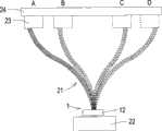
图2是将图1所示的固定式供墨管固定机构应用于打印机中的运作流程示意图。FIG. 2 is a schematic diagram of the operation flow of applying the fixed ink supply tube fixing mechanism shown in FIG. 1 to a printer.
图3是本发明第二较佳实施例的万向式供墨管固定机构的结构示意图。Fig. 3 is a schematic structural view of the universal ink supply tube fixing mechanism according to the second preferred embodiment of the present invention.
图4(a)~(d)是将图3所示的万向式供墨管固定机构应用于打印机中的运作流程示意图。4( a ) to ( d ) are schematic diagrams of the operation flow of applying the universal ink supply tube fixing mechanism shown in FIG. 3 to a printer.
具体实施方式Detailed ways
体现本发明特征与优点的一些典型实施例将在下面的说明中予以详细叙述。应理解的是本发明能够在不同的态样上具有各种的变化,其皆不脱离本发明的范围,且其中的说明及图示在本质上是当作说明之用,而非用以限制本发明。Some typical embodiments embodying the features and advantages of the present invention will be described in detail in the following description. It should be understood that the invention is capable of various changes in different aspects without departing from the scope of the invention, and that the description and illustrations therein are illustrative in nature and not limiting. this invention.
本发明是一种供墨管固定机构,其适用于使用连续供墨系统的一打印输出装置,例如:打印机(未图示)中,主要是由支撑部及导引部所组成,用以支撑及导引与墨水匣(未图示)相连接的供墨管于墨水匣运作时进行相对应的运动。The present invention is an ink supply tube fixing mechanism, which is suitable for a printing output device using a continuous ink supply system, for example: in a printer (not shown), it is mainly composed of a support part and a guide part for supporting And guide the ink supply tube connected with the ink cartridge (not shown) to move correspondingly when the ink cartridge is in operation.
请参阅图1,其是本发明第一较佳实施例的固定式供墨管固定机构的结构示意图,如图所示,采用固定式的供墨管固定机构1主要由支撑部11、导引部12及锁固元件13所组成,支撑部11可利用锁固或卡合的方式固定于打印机的壳体表面或内部,且具有一表面111,而表面111上则具有一孔洞(未图示)。Please refer to Fig. 1, which is a schematic structural view of the fixed ink supply tube fixing mechanism of the first preferred embodiment of the present invention. As shown in the figure, the fixed ink supply
导引部12的部份结构具有一螺纹部(未图示),可穿过该孔洞并利用锁固元件13,例如:螺帽,将导引部12锁固于支撑部11的表面111上,且导引部12具有一通道121,用来使至少一供墨管21(如图2所示)贯穿通道121使供墨管21的部分结构置于通道121中,用以支撑并限制供墨管21于墨水匣进行打印运作时供墨管21的运动范围,其中,于本实施例中导引部12可为一圆环结构,但不以此为限。Part of the structure of the
请参阅图2,其是将图1所示的固定式供墨管固定机构应用于打印机中的运作流程示意图,如图2所示,供墨管21的一端可与一供墨平台22相连接,而另一端则于贯穿固定机构1的导引部12的通道121(如图1所示)后与装载于一容置框体23中的墨水匣(未图示)相连接,借以将墨水自供墨平台22输送至容置框体23中的墨水匣,而容置框体23是装载于一承载架24上,墨水匣的喷墨头(未图示)的运作是配合容置框体23于承载架24上的进行左右来回移动,如图所示,当容置框体23移动至如A、B、C或D等不同位置时,导引部12导引供墨管21随着容置框体23的移动进行相对应的运动,并将供墨管21的运动范围限制在导引部12的通道121(如图1所示)中,确保供墨管21能顺利进行供墨且不会于墨水匣移动时发生四散或压折的情形而影响到其他元件的运作。Please refer to Figure 2, which is a schematic diagram of the operation process of applying the fixed ink supply tube fixing mechanism shown in Figure 1 to a printer, as shown in Figure 2, one end of the
请参阅图3,其是本发明第二较佳实施例的万向式供墨管固定机构的结构示意图,如图所示,采用万向式的供墨管固定机构3主要由支撑部31、转动部32及导引部33所组成,支撑部31同样可利用锁固或卡合的方式固定于打印机的壳体表面或内部,另外支撑部31还具有一容置槽(未图示),而转动部32可包含一球状体321,其部份容置于支撑部31的容置槽中,用以使转动部32可进行转动。Please refer to FIG. 3 , which is a schematic structural view of the universal ink supply tube fixing mechanism of the second preferred embodiment of the present invention. As shown in the figure, the universal ink supply
导引部33固定于转动部32上且具有一通道331,用来使至少一供墨管41(如图4所示)贯穿通道331以使供墨管41的部分结构置于通道331中,用以支撑并限制供墨管41的运作范围,并于墨水匣进行打印运作时导引供墨管41进行相对应的运动,其中,导引部33可为一圆环结构,但不以此为限,当然,本发明不限于此第一实施例及第二实施例的态样,任何能支撑及导引供墨管并可进行轴转的组合态样均为本发明所适用的范围。The
请参阅图4(a)~(d),其是将图3所示的万向式供墨管固定机构应用于打印机中的运作流程示意图,如图4(a)所示,供墨管41的一端同样与供墨平台42相连接,而供墨管41的另一端则于贯穿固定机构3的导引部33的通道331(如图3所示)后与装载于一容置框体43中的墨水匣(未图示)相连接,借以将墨水自供墨平台42输送至容置框体43中的墨水匣,而容置框体43是装载于一承载架44上,墨水匣的喷墨头(未图示)的运作须配合容置框体43于承载架44上进行左右来回移动,当容置框体23移动至如图4(a)、图4(b)、图4(c)或图4(d)所示的A、B、C或D位置时,转动部32相应墨水匣沿着供墨管41的带动而同时进行转动,以带动导引部33转动进而引导供墨管41随着容置框体23的运作方向进行相对应的运动,并将供墨管41的运动范围限制在导引部33的通道331(如图3所示)中,确保供墨管41能顺利进行供墨且不会于墨水匣移动时发生四散的情形而影响到其他元件的运作,也可防止发生管线压折的情形。Please refer to Figure 4(a)~(d), which are schematic diagrams of the operation process of applying the universal ink supply tube fixing mechanism shown in Figure 3 to a printer, as shown in Figure 4(a), the
综上所述,本发明的供墨管固定机构是借助导引部的通道支撑至少一供墨管,并随着墨水匣的运作而导引至少一供墨管进行相对应的运动,本发明具有下述优点:To sum up, the ink supply tube fixing mechanism of the present invention supports at least one ink supply tube through the channel of the guide part, and guides at least one ink supply tube to perform corresponding movements with the operation of the ink cartridge. Has the following advantages:
1.供墨管固定机构于进行打印工作时是将供墨管的X、Y、Z方向的运动范围限制在导引部的通道中,可确保在打印过程中不会影响到墨水匣或其他元件的运作;1. The ink supply tube fixing mechanism limits the movement range of the ink supply tube in the X, Y, and Z directions to the channel of the guide part during printing, so as to ensure that the ink cartridge or other components will not be affected during the printing process. operation of components;
2.供墨管固定机构同时具有支撑及导引供墨管的功能,其可有效避免供墨管因喷墨头及墨水匣的运作及移动而发生四散进而导致其他元件的动作受阻、失效或故障,甚至损及墨水匣而发生打印时断墨或是漏墨的情况;2. The ink supply tube fixing mechanism also has the function of supporting and guiding the ink supply tube, which can effectively prevent the ink supply tube from being scattered due to the operation and movement of the inkjet head and ink cartridge, which will cause the movement of other components to be blocked, fail or Failure, or even damage to the ink cartridge, resulting in ink breakage or ink leakage during printing;
3.另外,万向式供墨管固定机构中的转动部可相应墨水匣沿着供墨管的驱动而进行轴转,进而带动导引部转动,使导引部能随着墨水匣的运作方向而导引供墨管进行相对应的运动,如此一来可有效防止供墨管发生压折甚至因此损坏,同时也避免了断墨或漏墨的情形发生;3. In addition, the rotating part in the universal ink supply tube fixing mechanism can rotate along the axis of the ink cartridge according to the drive of the ink supply tube, and then drive the guide part to rotate, so that the guide part can follow the operation of the ink cartridge Guide the ink supply tube to move in a corresponding direction, so that it can effectively prevent the ink supply tube from being buckled or even damaged, and at the same time avoid the occurrence of ink breakage or ink leakage;
4.借助供墨管固定机构支撑及导引供墨管,使供墨管与打印机中其他元件的相对位置及其因墨水匣的驱动所产生的运动受到有效的限制且获得良好的导引,不仅大幅降低了连续供墨系统的故障率,还相对提升了供墨效率及供墨品质;4. Support and guide the ink supply tube with the help of the ink supply tube fixing mechanism, so that the relative position of the ink supply tube and other components in the printer and the movement generated by the drive of the ink cartridge are effectively restricted and well guided, Not only greatly reduces the failure rate of the continuous ink supply system, but also relatively improves the ink supply efficiency and ink supply quality;
Claims (10)
Priority Applications (3)
| Application Number | Priority Date | Filing Date | Title |
|---|---|---|---|
| CNB200610121528XACN100519202C (en) | 2006-08-17 | 2006-08-17 | Ink supply tube fixing mechanism |
| RU2007132351/12ARU2007132351A (en) | 2006-08-17 | 2007-08-16 | LOCKING DEVICE FOR INK TRANSFER TUBE |
| BRPI0706120BRPI0706120A2 (en) | 2006-08-17 | 2007-08-17 | clamping mechanism for an ink transfer tube |
Applications Claiming Priority (1)
| Application Number | Priority Date | Filing Date | Title |
|---|---|---|---|
| CNB200610121528XACN100519202C (en) | 2006-08-17 | 2006-08-17 | Ink supply tube fixing mechanism |
Publications (2)
| Publication Number | Publication Date |
|---|---|
| CN101125485A CN101125485A (en) | 2008-02-20 |
| CN100519202Ctrue CN100519202C (en) | 2009-07-29 |
Family
ID=39093652
Family Applications (1)
| Application Number | Title | Priority Date | Filing Date |
|---|---|---|---|
| CNB200610121528XAExpired - Fee RelatedCN100519202C (en) | 2006-08-17 | 2006-08-17 | Ink supply tube fixing mechanism |
Country Status (1)
| Country | Link |
|---|---|
| CN (1) | CN100519202C (en) |
Citations (4)
| Publication number | Priority date | Publication date | Assignee | Title |
|---|---|---|---|---|
| EP0808715A3 (en)* | 1996-05-24 | 1998-10-07 | Hewlett-Packard Company | Method and device to purge air from ink tubes during startup period |
| CN2673645Y (en)* | 2003-10-14 | 2005-01-26 | 叶健星 | Connecting device of continuous ink supply system |
| CN1663798A (en)* | 2004-03-05 | 2005-09-07 | 兄弟工业株式会社 | image recording device |
| CN2790757Y (en)* | 2005-06-03 | 2006-06-28 | 珠海天威飞马打印耗材有限公司 | Ink feeding conduit fixing structure for ink-jet printer |
- 2006
- 2006-08-17CNCNB200610121528XApatent/CN100519202C/ennot_activeExpired - Fee Related
Patent Citations (4)
| Publication number | Priority date | Publication date | Assignee | Title |
|---|---|---|---|---|
| EP0808715A3 (en)* | 1996-05-24 | 1998-10-07 | Hewlett-Packard Company | Method and device to purge air from ink tubes during startup period |
| CN2673645Y (en)* | 2003-10-14 | 2005-01-26 | 叶健星 | Connecting device of continuous ink supply system |
| CN1663798A (en)* | 2004-03-05 | 2005-09-07 | 兄弟工业株式会社 | image recording device |
| CN2790757Y (en)* | 2005-06-03 | 2006-06-28 | 珠海天威飞马打印耗材有限公司 | Ink feeding conduit fixing structure for ink-jet printer |
Also Published As
| Publication number | Publication date |
|---|---|
| CN101125485A (en) | 2008-02-20 |
Similar Documents
| Publication | Publication Date | Title |
|---|---|---|
| JP4008524B2 (en) | Ink supply interface mechanism | |
| US7866801B2 (en) | Liquid-supplying system and liquid-consuming apparatus | |
| US8991971B2 (en) | Liquid ejecting apparatus | |
| JP2011195278A (en) | Roll medium support device and recording apparatus | |
| CN102189839B (en) | Tape deck | |
| CN203032093U (en) | Liquid supply system and liquid consumption device | |
| CN100519202C (en) | Ink supply tube fixing mechanism | |
| JP5830886B2 (en) | Waste liquid container and liquid consumption device | |
| CN100509408C (en) | Ink supply tube fixing mechanism | |
| CN206991026U (en) | Printing module with print head moving mechanism | |
| JP5743529B2 (en) | Image forming apparatus | |
| JP2012196798A (en) | Waste liquid container and liquid consumption apparatus | |
| JP5732944B2 (en) | Waste liquid container and liquid consumption device | |
| JP2014240202A (en) | Waste liquid container and liquid consumption apparatus | |
| WO2015194154A1 (en) | Liquid supply unit, and liquid consuming system | |
| ATE507077T1 (en) | MULTIPLE FUNCTION APPARATUS, PRINTER AND DYE FEEDING APPARATUS THEREOF | |
| JP2016037018A (en) | Liquid supply unit | |
| TWI327964B (en) | Fixing mechanism of ink transfre pipe | |
| JP6079254B2 (en) | Ink supply system | |
| JP2000218822A (en) | Ink jet recording apparatus | |
| CN100446983C (en) | Ink Supply Containers for Continuous Ink Supply Systems | |
| JP2005041140A (en) | Ink jet recorder | |
| TWI288079B (en) | Fixing mechanism of ink transfer pipe | |
| CN204622832U (en) | A kind of for the print cartridge in ink-jet printer | |
| JP2012111041A (en) | Ink ribbon cartridge, and printer |
Legal Events
| Date | Code | Title | Description |
|---|---|---|---|
| C06 | Publication | ||
| PB01 | Publication | ||
| C10 | Entry into substantive examination | ||
| SE01 | Entry into force of request for substantive examination | ||
| C14 | Grant of patent or utility model | ||
| GR01 | Patent grant | ||
| CF01 | Termination of patent right due to non-payment of annual fee | ||
| CF01 | Termination of patent right due to non-payment of annual fee | Granted publication date:20090729 Termination date:20190817 |