CN100515512C - Safety trocar with progressive cutting tip guard and air jet tissue deflector - Google Patents
Safety trocar with progressive cutting tip guard and air jet tissue deflectorDownload PDFInfo
- Publication number
- CN100515512C CN100515512CCNB038054701ACN03805470ACN100515512CCN 100515512 CCN100515512 CCN 100515512CCN B038054701 ACNB038054701 ACN B038054701ACN 03805470 ACN03805470 ACN 03805470ACN 100515512 CCN100515512 CCN 100515512C
- Authority
- CN
- China
- Prior art keywords
- blade
- cutting point
- surgical device
- handle
- protector
- Prior art date
- Legal status (The legal status is an assumption and is not a legal conclusion. Google has not performed a legal analysis and makes no representation as to the accuracy of the status listed.)
- Expired - Fee Related
Links
- 238000005520cutting processMethods0.000titleclaimsabstractdescription127
- 230000000750progressive effectEffects0.000titledescription3
- 239000012530fluidSubstances0.000claimsabstractdescription14
- 230000001012protectorEffects0.000claimsdescription27
- 230000007246mechanismEffects0.000claimsdescription17
- 238000000034methodMethods0.000claimsdescription13
- 230000008569processEffects0.000claimsdescription7
- 230000004044responseEffects0.000claimsdescription3
- 238000006243chemical reactionMethods0.000claims1
- 210000001835visceraAnatomy0.000abstractdescription22
- 230000035515penetrationEffects0.000abstractdescription17
- 238000003780insertionMethods0.000abstractdescription9
- 230000037431insertionEffects0.000abstractdescription9
- 230000006378damageEffects0.000abstractdescription7
- 238000013461designMethods0.000abstractdescription6
- 238000012976endoscopic surgical procedureMethods0.000abstractdescription3
- 210000001519tissueAnatomy0.000description58
- CURLTUGMZLYLDI-UHFFFAOYSA-NCarbon dioxideChemical compoundO=C=OCURLTUGMZLYLDI-UHFFFAOYSA-N0.000description24
- 230000009471actionEffects0.000description15
- 229910002092carbon dioxideInorganic materials0.000description12
- 239000001569carbon dioxideSubstances0.000description11
- 210000000683abdominal cavityAnatomy0.000description10
- 208000014674injuryDiseases0.000description9
- 208000027418Wounds and injuryDiseases0.000description7
- 230000001681protective effectEffects0.000description7
- 230000000694effectsEffects0.000description5
- 210000000056organAnatomy0.000description3
- 230000003187abdominal effectEffects0.000description2
- 210000003815abdominal wallAnatomy0.000description2
- 230000009977dual effectEffects0.000description2
- 230000000977initiatory effectEffects0.000description2
- 238000004519manufacturing processMethods0.000description2
- 230000008520organizationEffects0.000description2
- 238000007789sealingMethods0.000description2
- 238000001356surgical procedureMethods0.000description2
- 230000008733traumaEffects0.000description2
- 238000003466weldingMethods0.000description2
- 208000012260Accidental injuryDiseases0.000description1
- 206010002091AnaesthesiaDiseases0.000description1
- 229910000831SteelInorganic materials0.000description1
- 206010052428WoundDiseases0.000description1
- 230000037005anaesthesiaEffects0.000description1
- 230000009286beneficial effectEffects0.000description1
- 230000006835compressionEffects0.000description1
- 238000007906compressionMethods0.000description1
- 239000012141concentrateSubstances0.000description1
- 230000007812deficiencyEffects0.000description1
- 230000000994depressogenic effectEffects0.000description1
- 238000007598dipping methodMethods0.000description1
- 238000001839endoscopyMethods0.000description1
- 230000003511endothelial effectEffects0.000description1
- 210000005081epithelial layerAnatomy0.000description1
- 238000003384imaging methodMethods0.000description1
- 238000002347injectionMethods0.000description1
- 239000007924injectionSubstances0.000description1
- 230000013011matingEffects0.000description1
- 238000002324minimally invasive surgeryMethods0.000description1
- 238000012986modificationMethods0.000description1
- 230000004048modificationEffects0.000description1
- 238000012544monitoring processMethods0.000description1
- 210000003205muscleAnatomy0.000description1
- 230000008816organ damageEffects0.000description1
- 230000000149penetrating effectEffects0.000description1
- 238000004445quantitative analysisMethods0.000description1
- 230000009467reductionEffects0.000description1
- 230000000717retained effectEffects0.000description1
- 238000012552reviewMethods0.000description1
- 238000000926separation methodMethods0.000description1
- 239000010959steelSubstances0.000description1
- 230000002792vascularEffects0.000description1
- 238000013022ventingMethods0.000description1
Images


Classifications
- A—HUMAN NECESSITIES
- A61—MEDICAL OR VETERINARY SCIENCE; HYGIENE
- A61M—DEVICES FOR INTRODUCING MEDIA INTO, OR ONTO, THE BODY; DEVICES FOR TRANSDUCING BODY MEDIA OR FOR TAKING MEDIA FROM THE BODY; DEVICES FOR PRODUCING OR ENDING SLEEP OR STUPOR
- A61M31/00—Devices for introducing or retaining media, e.g. remedies, in cavities of the body
- A—HUMAN NECESSITIES
- A61—MEDICAL OR VETERINARY SCIENCE; HYGIENE
- A61B—DIAGNOSIS; SURGERY; IDENTIFICATION
- A61B17/00—Surgical instruments, devices or methods
- A61B17/34—Trocars; Puncturing needles
- A61B17/3494—Trocars; Puncturing needles with safety means for protection against accidental cutting or pricking, e.g. limiting insertion depth, pressure sensors
- A61B17/3496—Protecting sleeves or inner probes; Retractable tips
- A—HUMAN NECESSITIES
- A61—MEDICAL OR VETERINARY SCIENCE; HYGIENE
- A61B—DIAGNOSIS; SURGERY; IDENTIFICATION
- A61B17/00—Surgical instruments, devices or methods
- A61B17/34—Trocars; Puncturing needles
- A61B17/3494—Trocars; Puncturing needles with safety means for protection against accidental cutting or pricking, e.g. limiting insertion depth, pressure sensors
- A—HUMAN NECESSITIES
- A61—MEDICAL OR VETERINARY SCIENCE; HYGIENE
- A61B—DIAGNOSIS; SURGERY; IDENTIFICATION
- A61B17/00—Surgical instruments, devices or methods
- A61B17/34—Trocars; Puncturing needles
- A61B17/3417—Details of tips or shafts, e.g. grooves, expandable, bendable; Multiple coaxial sliding cannulas, e.g. for dilating
- A—HUMAN NECESSITIES
- A61—MEDICAL OR VETERINARY SCIENCE; HYGIENE
- A61B—DIAGNOSIS; SURGERY; IDENTIFICATION
- A61B17/00—Surgical instruments, devices or methods
- A61B17/34—Trocars; Puncturing needles
- A61B17/3474—Insufflating needles, e.g. Veress needles
- A—HUMAN NECESSITIES
- A61—MEDICAL OR VETERINARY SCIENCE; HYGIENE
- A61B—DIAGNOSIS; SURGERY; IDENTIFICATION
- A61B17/00—Surgical instruments, devices or methods
- A61B2017/00535—Surgical instruments, devices or methods pneumatically or hydraulically operated
- A61B2017/00544—Surgical instruments, devices or methods pneumatically or hydraulically operated pneumatically
- A—HUMAN NECESSITIES
- A61—MEDICAL OR VETERINARY SCIENCE; HYGIENE
- A61B—DIAGNOSIS; SURGERY; IDENTIFICATION
- A61B17/00—Surgical instruments, devices or methods
- A61B17/34—Trocars; Puncturing needles
- A61B17/3417—Details of tips or shafts, e.g. grooves, expandable, bendable; Multiple coaxial sliding cannulas, e.g. for dilating
- A61B2017/3454—Details of tips
- A61B2017/346—Details of tips with wings
Landscapes
- Health & Medical Sciences (AREA)
- Life Sciences & Earth Sciences (AREA)
- Surgery (AREA)
- Public Health (AREA)
- Animal Behavior & Ethology (AREA)
- Engineering & Computer Science (AREA)
- Biomedical Technology (AREA)
- Heart & Thoracic Surgery (AREA)
- Veterinary Medicine (AREA)
- General Health & Medical Sciences (AREA)
- Nuclear Medicine, Radiotherapy & Molecular Imaging (AREA)
- Molecular Biology (AREA)
- Pathology (AREA)
- Medical Informatics (AREA)
- Anesthesiology (AREA)
- Hematology (AREA)
- Surgical Instruments (AREA)
- Infusion, Injection, And Reservoir Apparatuses (AREA)
Abstract
Description
Translated fromChinese发明背景Background of the invention
本申请是美国申请号为09/598,453申请的部分继续申请,该申请2000年6月22日提出,目前未决,在此告知以供结合参考。This application is a continuation-in-part of US Application No. 09/598,453, filed June 22, 2000, which is currently pending and is hereby incorporated by reference.
技术领域technical field
本申请涉及一种外科手术设备,特别地,涉及一种包括一个或多个结构部件的外科手术设备,使设备能安全使用。The present application relates to a surgical device and, in particular, to a surgical device comprising one or more structural components to enable safe use of the device.
背景技术Background technique
大多数已有的用于内窥镜手术过程的套针在套针插入和操作时不能确实有效防止内部器官受损。尽管进一步努力改进现有套针结构,结果仍然不佳。现有套针常常伤害内部器官,有时导致的伤口严重甚至致命。因此迫切需要更安全的套针,特别是在将来内窥镜手术过程的应用可能变得更加广泛。Most existing trocars for endoscopic surgical procedures do not reliably prevent internal organ damage during trocar insertion and manipulation. Despite further efforts to improve existing trocar structures, results have remained poor. Existing trocars often injure internal organs, sometimes resulting in serious or even fatal wounds. There is thus an urgent need for safer trocars, especially as endoscopic surgical procedures may become more widely used in the future.
内窥镜或极小的侵入手术提供了改进现有外科手术过程和使外科手术过程仪表化的机会,可与之相比的只有19世纪引入麻醉药这种革命性的效应。Endoscopy, or minimally invasive surgery, offers the opportunity to improve and instrument existing surgical procedures comparable only to the revolutionary effects of the introduction of anesthesia in the 19th century.
大多现有套针使用尖端的“护罩”,或盖,用作切割刃,在刺入体腔后通常立即展开。这样刺入伴有伤害内部器官的危险。不管外科医生可能在刺入体腔过程中如何细致,在伤害内部器官前的最后时侯刺入阻力会变小。这种在刺入中的阻力突然变小被称为“陷入效应”并出现在任何安全部件使用之前。在有些套针中,刺入通过一些方式进行控制,在出现小的增量时起作用或者使用一些类似直接观察,估算,或监控的方式。然而,所有这些情况设计的结果都是在任何保护设备使用之前使刺穿尖插入很多直到危险深度。也许这并不意外,因为在任何保护使用前必须开孔。Most existing trocars use a pointed "shield," or cap, that acts as a cutting edge and usually unfolds immediately after penetration into a body cavity. Such penetration is accompanied by the risk of injury to internal organs. No matter how meticulous a surgeon may be in penetrating a body cavity, there is less resistance to penetration during the last moments before injuring internal organs. This sudden reduction in resistance in penetration is called the "entrapment effect" and occurs before any safety features are used. In some trocars, penetration is controlled by means of acting in small increments or using something like direct observation, estimation, or monitoring. However, the result of all these case designs is that the piercing point is inserted many times to a dangerous depth before any protective equipment is used. Perhaps this is not surprising, as holes must be drilled before any protection can be used.
由于大多情况下柔弱的器官与被刺穿的皮肤层内侧非常接近,可行的是在内腔充满二氧化碳后再进行刺穿操作,以减小由于接触到器械锋利的刺穿尖或切割刃而引起的意外伤害的危险。然而大多情况下,刺穿需要的力和肌肉层的弹性特征造成了手术开口处严重陷下,因此使得器械的刺穿尖更接近内部器官。某些情况下,突然刺穿腔壁和阻力迅速的减小使得器械被推进的深度远大于预期深度或可以控制的深度。此外,组织壁与任何保护设备之间的摩擦也会迟滞该保护设备的使用,伤害几乎是不能避免发生的。Since the delicate organs are very close to the inner side of the punctured skin layer in most cases, it is feasible to perform the puncture operation after the inner cavity is filled with carbon dioxide to reduce the risk of injury caused by contact with the sharp puncture point or cutting edge of the instrument. risk of accidental injury. In most cases, however, the force required for piercing and the elastic characteristics of the muscle layer cause severe depression of the surgical opening, thus bringing the piercing tip of the instrument closer to the internal organs. In some cases, the sudden penetration of the lumen wall and the rapid decrease in resistance allow the instrument to be advanced farther than intended or controllable. In addition, friction between the tissue wall and any protective device can retard the use of that protective device, and injury is almost inevitable.
发明内容Contents of the invention
因此,本发明的一个目的,是通过将外科手术设备中器械的剌穿尖或切割刃与柔弱的组织之间始终保持足够的距离,以确保避免这种伤害。因此,即使在动态条件下,也会减少伤害发生的可能性。It is therefore an object of the present invention to ensure the avoidance of such injuries by always maintaining a sufficient distance between the piercing points or cutting edges of instruments in surgical equipment and delicate tissue. Thus, even under dynamic conditions, the likelihood of injury occurring is reduced.
本发明的另一个目的是提供一种外科手术设备,可以在体腔的刺穿过程中,靠该手术设备给病人送进吹入流体,以在刺穿过程中推动内部器官远离手术设备。本发明的吹入流体可以由任何外部加压储存器供给,或者在体腔刺穿过程中由该手术设备进行压缩(并由此集中)而供给。Another object of the present invention is to provide a surgical device by which an insufflation fluid can be delivered to a patient during piercing of a body cavity to push internal organs away from the surgical device during piercing. The insufflation fluid of the present invention may be supplied from any external pressurized reservoir, or compressed (and thus concentrated) by the surgical device during body cavity piercing.
本发明的另一个目的是提供一种外科手术设备,它包括一个或多个切割刃,在体腔刺穿过程中在切割刃和组织之间产生低摩擦力,从而减小推动该手术设备进入体腔所需要的力。Another object of the present invention is to provide a surgical device that includes one or more cutting edges that create low friction between the cutting edge and tissue during body cavity penetration, thereby reducing the need to push the surgical device into the body cavity. the force required.
本发明的另一个目的是提供一种外科手术设备,包括的保护设备在使用时保持基本不与组织接触,从而减少保护设备间的摩擦力并确保可控制它便利的使用。Another object of the present invention is to provide a surgical device comprising protective devices which remain substantially out of contact with tissue during use, thereby reducing friction between the protective devices and ensuring a controlled and convenient use thereof.
本发明的另一个目的是提供一种外科手术设备,包括的保护设备例如安全防护器,其中防护元件具有顶点并且顶点的预定角度要小于手术设备刀片或切割元件的预定角度,从而确保在保护设备使用的过程中逐渐覆盖刀片或切割元件。本发明中使用的术语“刀片”表示一个或多个刀片。Another object of the present invention is to provide a surgical device, including a protective device such as a safety guard, wherein the protective element has an apex and the predetermined angle of the apex is smaller than the predetermined angle of the surgical device blade or cutting element, thereby ensuring the Gradually cover the blade or cutting element during use. The term "blade" as used herein means one or more blades.
本发明的另一个目的是提供一种外科手术设备,带有夹持机构以方便在体腔刺穿过程中该手术设备的夹持和扭转。Another object of the present invention is to provide a surgical device with a gripping mechanism to facilitate gripping and twisting of the surgical device during body cavity penetration.
本发明的另一个目的是提供一种外科手术设备,包括锁紧系统以防止在尖部已被使用后切割元件意外再次使用。Another object of the present invention is to provide a surgical device comprising a locking system to prevent accidental re-use of the cutting element after the tip has been used.
因此期望本发明,总体上改善手术的安全性。The present invention is therefore expected to improve the safety of surgery in general.
这些及其他目的在第一实施例中实现,其中的外科手术设备例如套针组织刺穿器包括一套薄的平的箭尖状的切割刀片,它们在切割尖同轴处结合,位于中空圆柱刺穿器中,并具有以切割角集中于切割尖的切割刃。这套切割刀片的外侧后面可以固定在中空圆柱刺穿器内并使切割刃完全露出。中空圆柱可以在它的前端开槽,并且每一段形成三角形并弯曲以配合在刀刃之间,并使它的边缘与突出的刀片的刃基本平行,在轴向凹进到该边缘之后,作为组织扩张器以防止内侧移动的防护器和外侧的组织之间的接触。在中空圆柱刺穿器端部的三角形弯曲部分的组织扩张器之间的槽可以足够宽,使得它们和切割刀片侧面之间能够通过防护片,至少有刀片的厚度。一套轴向细长弯曲的片状防护器设置为可以在切割刀片侧面和中空圆柱的三角形弯曲部分之间的间隔内自由滑动,并在前端具有比临近刀刃的角更尖的顶锥角形状,并以很小的钝的圆尖结束。弯曲的片状防护器的带角的前端可以具有浅的带角度的端部并朝向边缘缓慢弯曲,因此任何时候它们的角度都不会超过临近切割刃的角度。插入到切割刀片和中空圆柱的三角形弯曲部分之间的细长的弯曲的片状防护器,可以将它相反端附着在杆上,靠螺旋弹簧向前面的切割刃加载。These and other objects are achieved in a first embodiment in which the surgical device, such as a trocar tissue piercer, comprises a set of thin, flat, arrow-pointed cutting blades joined coaxially at the cutting tips, located in a hollow cylindrical The piercer has a cutting edge centered on the cutting tip at a cutting angle. The outer rear of the set of cutting blades can be fixed in the hollow cylindrical piercer and fully expose the cutting edge. The hollow cylinder may be slotted at its front end, and each segment formed into a triangle and bent to fit between the blades, and to make its edge substantially parallel to the edge of the protruding blade, after being axially recessed into the edge, as tissue The dilator prevents contact between the medial moving guard and the tissue on the outer side. The slots between the tissue expanders in the triangular bend at the end of the hollow cylindrical piercer may be wide enough to allow passage of guard plates, at least the thickness of the blade, between them and the sides of the cutting blade. A set of axially slender and curved sheet guards arranged to slide freely in the space between the side of the cutting blade and the triangular curved portion of the hollow cylinder, and having a tip cone shape at the front end that is sharper than the corner adjacent to the blade , and ends in a very small blunt rounded point. The angled front ends of the curved sheet guards may have shallow angled ends and curve slowly towards the edge so that at no time are they angled more than the adjacent cutting edge. An elongated curved sheet guard inserted between the cutting blade and the triangular curved portion of the hollow cylinder may be attached at its opposite end to a rod, loaded against the cutting edge in front by a helical spring.
该手术设备的有益特性包括,举例如下:Beneficial properties of the surgical device include, for example, the following:
-锋利的平面刀刃的多系统几乎消除了侧面摩擦并减小了刺穿的阻力,因此减少了刺穿的“陷入效应”和组织回弹。- The multi-system of sharp flat blades virtually eliminates side friction and reduces resistance to penetration, thus reducing the "dipping effect" of penetration and tissue rebound.
-组织保护的机械设备包括一系列薄的塑性防护器沿着平面刀的侧面滑动,在优选实施例中,它们的边缘之间的角度小于切割刀刃之间的角度。然后可以表示出,这些防护器的边缘有了适合的轮廓,就可以从刺穿刚开始时在切割刃和周围的组织之间提供完全的防护,而且是用真正渐进的方式进行,没有急进或不连续。由于防护器侧面之间的角度比切割刀片刃之间的角度更小而造成的渐进的防护动作,使得防护器陷入到由切割尖形成的微小的开口中并马上覆盖它,因此防止了在套针插入的最关键时刻对内部器官的伤害。因此,防护动作以真正渐进的方式进行,当切割刀片继续扩张微小的起始开口时,防护器逐渐前进,保持切割刃不断覆盖刺穿区域的外侧并隔离内部器官,直到刺穿完成,套管完全插入;- The mechanical device for tissue protection consists of a series of thin plastic guards that slide along the sides of the planar knife, in a preferred embodiment, the angle between their edges being smaller than the angle between the cutting blades. It can then be shown that with the edges of these guards properly contoured, it is possible to provide complete protection between the cutting edge and the surrounding tissue from the very beginning of the penetration, and in a truly gradual manner, with no sharp or sharp advances. Discontinuous. The progressive guarding action due to the smaller angle between the guard sides than the cutting blade edges causes the guard to sink into the tiny opening formed by the cutting tip and immediately cover it, thus preventing the Injury to internal organs at the most critical moment of needle insertion. So the guarding action works in a truly progressive manner, as the cutting blade continues to expand the tiny initial opening, the guard progressively advances, keeping the cutting edge continuously covering the outside of the pierced area and isolating the internal organs until the piercing is complete and the cannula fully inserted;
-一个或多个固定的圆锥偏转器以扩张切割组织的通道,使防护器只在它们的尖部与组织相接触,因此在刺穿尖的侧面隔离防护器与组织的摩擦。因此,一旦切割刀片形成了即使是微小的开口,防护器立刻陷入开口并防止刀片尖接触内部器官。因此,使用防护器外的组织扩张器防止了防护器和组织之间的摩擦,这将延缓使用动作。- One or more fixed conical deflectors to expand the passage of the cut tissue so that the guards only contact the tissue at their tips, thus isolating the friction of the guards with the tissue on the sides of the piercing point. Thus, once the cutting blade has formed even a tiny opening, the guard sinks into the opening and prevents the blade tip from contacting internal organs. Thus, using a tissue expander outside the guard prevents friction between the guard and tissue, which would delay the action of use.
使用这种组织扩张器使得安全设备的运行没有限制,因此消除了现有套针的一项主要的不足。换句话说,防护器的动态回应在本质上远快于刀片刺穿的速率。结果,切割刃从未危险的露出接触到内部器官,无论刺穿速率可以有多快;The use of such a tissue expander allows for unlimited operation of the safety device, thereby eliminating a major deficiency of existing trocars. In other words, the dynamic response of the guard is inherently much faster than the rate of blade penetration. As a result, the cutting edge is never dangerously exposed to contact internal organs, no matter how fast the penetration rate may be;
-吹入通道配置用来在刺穿过程中传送流体到体腔内。吹入通道加压可以使用外部储存器或者靠在刺穿过程中压缩容纳在吹入通道中的气体。一旦上皮层开始被刺穿,吹入通道中的流体将推动内部器官远离切割刃。在使用外部二氧化碳气体储存器情况下,二氧化碳气体阀被打开,因此对刺穿器管体加压。这样加压,由于前面被组织包围,切割尖刺穿组织同时防止气体排出,但是一旦最微小的开口在尖部开始出现,气体突然膨胀进入开口并强制使柔弱的内部器官偏离开切割表面的尖端,同时防护器靠它们的弹簧施力进入开口。使用加压的流体(或气体)组织偏离器,由此在切割刃尖的前面,在初始刺穿的时候,甚至是在防护器尖陷入开口之前,制造了一个没有组织的区域。还必须指出的是,由于气流出现在切割刀片和圆锥扩张器之间,正是防护器所在的位置,因此突然的气体膨胀也可以帮助防护器的使用。几乎可以说防护器是由流体流吐出来的。这加快了它们投入使用的速度并因此形成手术设备的全面的安全。- The insufflation channel is configured to deliver fluid into the body cavity during piercing. Insufflation channel pressurization may use an external reservoir or rely on compression of the gas contained in the insufflation channel during piercing. Once the epithelial layer begins to be pierced, fluid blown into the channel will push the internal organs away from the cutting edge. In the case of an external carbon dioxide gas reservoir, the carbon dioxide gas valve is opened, thus pressurizing the piercer barrel. Pressurized in this way, the cutting tip pierces the tissue while preventing gas from escaping due to the tissue surrounding the front, but once the tiniest opening begins at the tip, the gas suddenly expands into the opening and forces the delicate internal organs away from the cutting surface at the tip , while the guards are forced into the opening by their spring force. A pressurized fluid (or gas) tissue deflector is used, thereby creating a tissue-free zone in front of the cutting tip, upon initial piercing, even before the guard tip sinks into the opening. It must also be noted that the sudden gas expansion can also aid in the use of the guard since the gas flow occurs between the cutting blade and the conical dilator, where the guard is located. It could almost be said that the guard is spit out by the fluid stream. This speeds up their commissioning and thus results in an overall safety of the surgical device.
-防护器的锁紧系统,位于器械的临近端,防止切割零件在尖端首次安全进入后意外的再次使用。套针防护器的锁紧系统包括锁紧圆柱附着在靠片簧支撑的锁紧按钮上并插入槽中。圆柱具有圆锥形尖部和底部的环形槽,可以通过按钮方式压下并靠这个槽啮合进U形弹簧中,这将把它固定在下面,允许其作滑动运动直到它从U形弹簧中出来,并准备好再次锁紧回到初始的位置。如果需要复位的动作,必须尽力向下推动锁紧按钮而为实现另一个循环慎重地进行复位。由于锁紧按钮位置深入手柄临近部分的凹陷中,需要一些努力才能到达并开动,因此很难意外复位。- The locking system of the guard, located at the proximal end of the instrument, prevents accidental re-use of the cut part after the tip has been safely entered for the first time. The locking system of the trocar guard consists of a locking cylinder attached to a locking button supported by a leaf spring and inserted into a slot. A cylinder with a conical tip and an annular groove at the base which can be pushed down by means of a button and by this groove engages into a U-shaped spring which will hold it underneath, allowing its sliding movement until it emerges from the U-shaped spring , and ready to lock back to the original position again. If a reset action is required, the locking button must be pushed down as hard as it can and reset carefully for another cycle. Since the locking button is located deep into the recess in the adjacent part of the handle, it takes some effort to reach and actuate, making it difficult to reset accidentally.
-人体工程设计以易于操作。临近的半球状把手很容易放在空手中,同时食指和中指把持侧角控制旋转,因此可以用非常自然舒适的方式推,拉,旋转,以及倾斜。-Ergonomically designed for easy handling. The adjacent hemispherical handle is easy to place in the empty hand, while the index and middle fingers hold the side angles to control the rotation, so it can be pushed, pulled, rotated, and tilted in a very natural and comfortable way.
最重要的特征是。如上面解释的,在这类套针中每个套针的每一套成对的刀片和防护器的动态的和功能的特征都是完全相同的。The most important feature is. As explained above, the dynamic and functional characteristics of each set of paired blades and guards are identical for each trocar in this type of trocar.
单刀片与双刀片套针之间主要的区别在于刀片的数量,这影响着刺穿组织的阻力。在双刀片实施例中开口是十字的,而单刀片的是线性的。结果,使用双刀片时的膨胀(例如被切割组织的伸展度)比使用单刀片时要小。由于任何套针的入口总会有膨胀,必须回顾与其相关的优点和缺点。最高膨胀发生在使用光滑的尖角圆锥套针时,因为这时没有切割而膨胀是全部的。有些外科医生喜欢它因为它提供了在入口周围的最好的密封和固定,并带有可能最小的血管伤害,但是它需要最高的刺穿力并有其他相关的外伤的影响,加上由于前方阻力突然停止前的高刺穿力造成的内部刺穿的危险;例如可怕的“陷入效应”。在入口的最大膨胀和由最大刃宽的四刃套针造成的膨胀之间,存在有两个极端,(多于四个全宽切割刃的在后面)。这是入口开口的两个极端。由于膨胀与简易刺穿是相反的,良好密封和高膨胀的要求与简易刺穿也是相反的。并没有清楚的方法可以客观定量地确定最好的套针尖部设计实现所希望的进入操作。The main difference between single-blade and dual-blade trocars is the number of blades, which affects resistance to tissue penetration. The opening is cross in the double blade embodiment and linear in the single blade embodiment. As a result, expansion (eg, stretching of the cut tissue) is less when using dual blades than when using a single blade. Since there will always be distension at the entry point of any trocar, the advantages and disadvantages associated with it must be reviewed. The highest expansion occurs when using a smooth-pointed conical trocar because there is no cutting and expansion is total. Some surgeons prefer it because it provides the best seal and fixation around the portal with the least possible vascular trauma, but it requires the highest penetration force and has other associated trauma effects, plus due to the anterior Danger of internal punctures due to high puncture forces before the resistance stops abruptly; eg the dreaded "entrapment effect". There are two extremes, between the maximum expansion of the inlet and the expansion caused by the maximum blade width four-bladed trocar, (behind with more than four full-width cutting edges). These are the two extremes of the entrance opening. Since expansion is inverse to easy puncture, the requirements for a good seal and high expansion are also inverse to easy puncture. There is no clear way to objectively and quantitatively determine the best trocar tip design to achieve the desired entry maneuver.
膨胀度可以通过线切割的总量和插入的套管圆周之间的数学关系定量确定,但是即使进行这样的定量分析,也不清楚什么是每个外科医生想要的。The degree of expansion can be quantitatively determined by the mathematical relationship between the total amount of wire cut and the circumference of the inserted cannula, but even with such a quantitative analysis, it is not clear what each surgeon wants.
上面叙述的两个套针实施例中任何一个,仅仅靠选择刀片的宽度,就可以设计为用于不同的膨胀度。两个刀片的实施例可以设计为带有很窄的刀刃宽度而变为高膨胀套针。对于单刀片实施例也是同样。还可以设计那些用于最宽刀片的套针,然后安装窄刀片获得需要的膨胀度或刺穿的简易度,并因此提供给外科医生在关键时刻可能需要的习惯的适合的器械。Either of the two trocar embodiments described above can be designed for different degrees of expansion simply by selecting the width of the blade. A two blade embodiment can be designed with a very narrow blade width to become a high expansion trocar. The same is true for the single blade embodiment. It is also possible to design those trocars for the widest blade and then install the narrower blade to achieve the desired expansion or ease of penetration, and thus provide the surgeon with a custom fit instrument that may be required at critical times.
然而,固有的,在相同刀片宽度内,双刀片实施例将有更低的膨胀并更易于套针进入,而单刀片实施例将有更高的膨胀并且比较难于进入。在任何情况下最好将它们中的每一种都设计为都在膨胀度和进入简易度的两个宽度界限之间,在给定的量或尺寸中。两种实施例之间的选择可以依靠制造和销售选择多于依靠专利特征。However, inherently, within the same blade width, a dual blade embodiment will have lower expansion and be easier to enter with a trocar, while a single blade embodiment will have higher expansion and be more difficult to access. In any case it is preferable to design each of them to be between the two width limits of expansion and ease of entry, in a given amount or size. The choice between the two embodiments may depend more on manufacturing and marketing options than on patented features.
附图说明Description of drawings
通过联系附图并参考下面的详细叙述将会获得本发明及其中附带的优点的更完全的评价及更好的理解,其中:A more complete appreciation and better understanding of the invention and the advantages attendant therein will be obtained by reference to the following detailed description in connection with the accompanying drawings, in which:
图1为总体视图,根据2000年6月23日提交的,申请系列号为09/598,453的原申请中我的初始概念,示出了套针第一实施例的立体图的形态;Figure 1 is a general view, showing the form of a perspective view of a first embodiment of a trocar, based on my initial concepts in the original application, Serial No. 09/598,453, filed June 23, 2000;
图2示出了该实施例套针的刺穿端的局部剖视图,其防护器被移到手术刀尖后面以更清楚示出该实施例的形状;Figure 2 shows a partial cross-sectional view of the piercing end of the trocar of this embodiment with the guard moved behind the tip of the scalpel to more clearly illustrate the shape of this embodiment;
图3示出了该实施例套针的相同端,其防护器已安装但在本实施例刺穿开始时缩回,因此,刀刃露出并准备开始切割;Figure 3 shows the same end of the trocar of this embodiment with the guard installed but retracted at the start of the piercing of this embodiment, so that the blade is exposed and ready to start cutting;
图4示出当切割尖刚开始刺穿腹腔时防护器尖伸出到切割尖前面;Figure 4 shows that the guard tip sticks out in front of the cutting tip when the cutting tip just begins to penetrate the abdominal cavity;
图5示出完全进入腹腔时,该实施例套针带有完全延伸的防护器并覆盖刀刃;Figure 5 shows that when fully entering the abdominal cavity, the trocar of this embodiment has a fully extended guard and covers the blade;
图6示出靠近皮肤层时的该实施例套针尖,此时防护器尖开始推向皮肤并收缩进入刺穿器;Figure 6 shows the trocar tip of this embodiment when it is close to the skin layer, when the guard tip starts to push against the skin and retracts into the piercer;
图7示出的是在该实施例中,防护器被完全推进收缩位置并且刀尖开始切割进入组织的时候;Figure 7 shows, in this embodiment, the guard is fully advanced into the retracted position and the knife tip begins cutting into tissue;
图8示出的是在该实施例中,刀尖完全通过组织并开始向腹腔的内皮层施力,因此防护器尖开始被推进初始开口,同时有力喷射加压的二氧化碳气体推动柔弱的内部组织从马上要刺穿的区域离开;Figure 8 shows that in this embodiment, the tip of the knife passes completely through the tissue and begins to apply force to the inner cortex of the abdominal cavity, so the guard tip begins to be pushed into the initial opening while a powerful jet of pressurized carbon dioxide gas pushes against the delicate inner tissue move away from the area that is about to be pierced;
图9示出的是在该实施例中,防护器尖刺穿开口并防止刀尖和周围的内部组织之间的任何接触,同时开口后露出的刀刃继续切割动作,而压缩气体的膨胀继续保持柔弱的组织远离切割区域;Figure 9 shows that in this embodiment, the guard tip pierces the opening and prevents any contact between the knife tip and the surrounding internal tissue, while the exposed knife edge behind the opening continues the cutting action while the expansion of the compressed gas continues to maintain Delicate tissue is kept away from the cutting area;
图10示出的是在该实施例中,继续刺穿,并且防护器几乎完全完成刺穿,同时在它们后面,仍露出的刃继续切割动作,而气体的通过也在继续;Figure 10 shows that in this embodiment the piercing continues and the guards almost completely complete the piercing, while behind them the still exposed edges continue the cutting action and the passage of gas continues;
图11示出的是在该实施例中,刺穿已经完成的时候,其中刀刃被防护器完全覆盖,而组织开口使套管的通过和吹入继续进行直到完成,从而刺穿器组件可以被移除;Figure 11 shows that in this embodiment, when the piercing has been completed, the blade is fully covered by the guard, and the tissue opening allows the passage and insufflation of the cannula to continue until complete so that the piercer assembly can be removed. remove;
图12示出了实施例套针手柄的顶视图,带有局部剖视图示出内部细节;Figure 12 shows a top view of an embodiment trocar handle with a partial cutaway showing internal details;
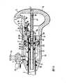
图13示出了沿垂直面“A-A”的纵向截面,列出了实施例套针手柄内部的大多数细节;Figure 13 shows a longitudinal section along the vertical plane "A-A", listing most details of the interior of the trocar handle of the embodiment;
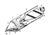
图14示出了实施例手柄的远侧部分的顶视图,带有夹持角以便于操作;Figure 14 shows a top view of the distal portion of an embodiment handle with gripping angles for ease of manipulation;
图15示出了实施例手柄的远侧部分从右侧看的侧视图,也具有局部剖视图部分详细示出了片状阀和控制杆;Figure 15 shows a side view from the right side of the distal portion of the embodiment handle, also with partial cutaway detailing the flap valve and lever;
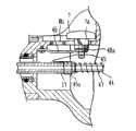
图16示出了防护器杆的实施例锁紧机构的局部立体视图,示出了手柄的临近部分中的一些元件,如同图13中截面“A-A”;Figure 16 shows a partial perspective view of an embodiment locking mechanism of the guard bar, showing some elements in the vicinity of the handle, as in section "A-A" in Figure 13;
图17示出了防护器杆锁紧机构的一些实施例元件空间位置的分解图;Figure 17 shows an exploded view of the spatial location of some embodiments of the guard bar locking mechanism;
图18示出了在锁紧位置的锁紧机构实施例;Figure 18 shows the locking mechanism embodiment in the locked position;
图19示出的锁紧机构实施例已经打开并准备开始刺穿;Figure 19 shows the locking mechanism embodiment has been opened and is ready to start piercing;
图20示出了向皮肤推动防护器如何迫使防护器杆向右;Figure 20 shows how pushing the guard against the skin forces the guard rod to the right;
图21示出了防护器完全缩回且刀刃完全露出以进行切割时杆的位置;Figure 21 shows the position of the rod when the guard is fully retracted and the blade is fully exposed for cutting;
图22示出了在腹腔内完全释放防护器后锁紧机构的位置并且锁紧它们的杆返回到图18中所示的初始位置;Figure 22 shows the position of the locking mechanisms after the guard has been fully released intraperitoneally and the levers locking them return to the initial position shown in Figure 18;
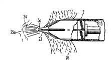
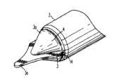
图23根据本发明第二实施例示出了套针立体形态的总体视图;Fig. 23 shows a general view of a three-dimensional form of a trocar according to a second embodiment of the present invention;
图24示出了该实施例套针的刺穿端的局部剖视图,其防护器被移到手术刀尖后面以更清楚示出该实施例的形状;Figure 24 shows a partial cross-sectional view of the piercing end of the trocar of this embodiment with the guard moved behind the tip of the scalpel to more clearly illustrate the shape of this embodiment;
图25示出了该实施例套针的相同端,其防护器已安装但在本实施例刺穿开始时缩回,因此,刀刃露出并准备开始切割;Figure 25 shows the same end of the trocar of this embodiment with the guard installed but retracted at the start of the piercing of this embodiment, so that the blade is exposed and ready to start cutting;
图26示出当切割尖刚开始刺穿腹腔时防护器尖伸出到切割尖前面;Figure 26 shows that the guard tip sticks out in front of the cutting tip when the cutting tip just begins to penetrate the abdominal cavity;
图27示出完全进入腹腔时,该实施例套针带有完全延伸的防护器并覆盖刀刃;Figure 27 shows the trocar of this embodiment with a fully extended guard covering the blade when fully entered into the abdominal cavity;
图28示出靠近皮肤层时的该实施例套针尖,此时防护器尖开始推向皮肤并收缩进入刺穿器;Figure 28 shows the trocar tip of this embodiment close to the skin layer when the guard tip begins to push against the skin and retracts into the piercer;
图29示出的是在该实施例中,防护器被完全推进收缩位置并且刀尖开始切割进入组织的时候;Figure 29 shows, in this embodiment, when the guard is fully advanced into the retracted position and the tip begins to cut into tissue;
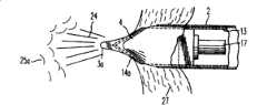
图30示出的是在该实施例中,刀尖完全通过组织并开始向腹腔的内皮层施力,因此防护器尖开始被推进初始开口,同时有力喷射加压的二氧化碳气体推动柔弱的内部组织从马上要刺穿的区域离开;Figure 30 shows that in this embodiment, the tip of the knife passes completely through the tissue and begins to apply force to the endothelial layer of the abdominal cavity, so the guard tip begins to be pushed into the initial opening while a powerful jet of pressurized carbon dioxide gas pushes against the delicate inner tissue move away from the area that is about to be pierced;
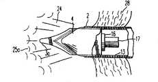
图31示出的是在该实施例中,防护器尖刺穿开口并防止刀尖和周围的内部组织之间的任何接触,同时开口后露出的刀刃继续切割动作,而压缩气体的膨胀继续保持柔弱的组织远离切割区域;Figure 31 shows that in this embodiment, the guard tip pierces the opening and prevents any contact between the knife tip and the surrounding internal tissue, while the blade edge exposed behind the opening continues the cutting action while the expansion of the compressed gas continues to maintain Delicate tissue is kept away from the cutting area;
图32示出的是在该第二实施例中,继续刺穿,并且防护器几乎完全完成刺穿,同时在它们后面,仍露出的刃继续切割动作,而气体的通过也在继续;Figure 32 shows that in this second embodiment the piercing continues and the guards are almost completely pierced while behind them the still exposed edges continue the cutting action and the passage of gas continues;
图33示出的是在本发明的该第二实施例中,当刺穿已经完成的时候。其中刀刃被防护器完全覆盖,而组织开口使套管的通过和吹入继续进行直到完成,从而刺穿器组件可以被移除。Figure 33 shows, in this second embodiment of the invention, when piercing has been completed. Where the blade is fully covered by the guard, the tissue opening allows passage and insufflation of the cannula to continue to completion so that the piercer assembly can be removed.
具体实施方式Detailed ways
现在参考附图,其中相同的标记数字表示同样的或对应的零件,特别参考其图1,其中在第一实施例中套管2牢固附着在手柄的末端部分,手柄由两段形成,末端6的一个外部包括夹持角6a,吹入设备11,和片状阀控制杆12,及形成半球把手形状的手柄临近部分5以便于手掌推动。这部分还包括带有平底9a的凹陷部9,并且外部机构包括插入的按钮7在槽8中滑动从而在套管2的极远端监视和控制安全防护器的位置。在远侧从套管2中伸出的安全机构包括圆锥形组织扩张器4,以及要覆盖一套手术刀(图1中未示出)的安全防护器3。这些是本发明外部可见的特征。Referring now to the drawings in which like reference numerals designate like or corresponding parts, and in particular to Figure 1 thereof, in which in a first embodiment a
图2示出了套针的刺穿末端的细节。中空的外圆柱2为套管,如图1中所示那样,牢固地附着在手柄6的末端部分。在套管2中,有另一个中空的圆柱13作为刺穿器。这是一个附着在手柄5的临近部分的可移动的部件,并可在刺穿完成后移去以引入手术器械。套管2具有如图中2a所示的末端斜面以便于穿过组织开口最小阻力引入器械。刺穿器中空圆柱13末端形成多个圆锥段扩张器4由槽4a间隔开以使扁尖刀14伸出并向器械中心集中,类似细箭头向中心集中。如图2中所示,手术刀位置在刺穿器中空圆柱13中的深度用14a表示。圆锥段扩张器之间的槽4a外的刀刃伸出一基本长度以保证充分切割。这套手术刀靠点焊15或其他类似机构装配在刺穿器圆柱13中。就在手术刀刃交叉的后面可以看到塑性防护器尖3a。在图2中,防护器被表示为从刀中移出以便于理解它们的形状和与手术刀的关系。防护器3的组件是支撑盘16的一部分,而支撑盘又是防护器中空杆17的一部分,将它们连接到手柄临近部分处的传动弹簧和锁紧机构(这里未示出)。在实际器械中,防护器尖3a插入刀刃周围且刀刃配合到防护器之间狭窄的空间3b中。然后防护器被向前推动组装直到它们从刀刃侧面和圆锥扩张器槽4a之间突出,如图3中所示。在图3中,防护器的尖刚刚可以看到因为当套针被首次推向皮肤时防护器会缩回。Figure 2 shows details of the piercing end of the trocar. The hollow
图4示出了防护器的尖3a突出到手术刀尖的前面并覆盖了它。防护器的尖3a之后很短的距离,手术刀14的刃露出并可以切割。图4示出了套针切割尖在刚开始刺穿腹部组织之后的外形。此时,防护器微小的尖3a穿过起始开口而陷入并迅速覆盖锋利的切割点,同时露出的刀刃继续在皮肤内切割直到刺穿完成,如图5中所示。图5示出了在进入到腹腔的刺穿完成之后实施例套针前端的样子。那时所有的切割刀刃被完全延伸的防护器覆盖,并且整个刺穿器部件可以靠手柄的临近部分拔出。Figure 4 shows that the
如接下来示出的,本发明的一方面,在腹腔壁首次进行穿孔时的瞬间,可以有力地喷射二氧化碳气体以使任何靠近刀尖的柔弱器官偏离开,同时防护器尖进入开口覆盖刀刃尖。As shown next, in one aspect of the invention, at the moment when the abdominal wall is first pierced, carbon dioxide gas can be injected forcefully to deflect any delicate organs near the tip of the knife while the guard tip enters the opening to cover the tip of the knife .
上述的操作是本发明的关键部分,因此它们将按照图6到图11的顺序更好的描述。The above-mentioned operations are key parts of the present invention, so they will be better described in the order of FIG. 6 to FIG. 11 .
图6表示出了开始接触皮肤层20时的实施例的套针防护器尖3a。表示在左侧的内部器官标记为25。这个时侯,皮肤外层在防护器尖的力的作用下凹陷,而防护器尖靠弹簧向前施力。当套针被向前推进,防护器将被迫进入刺穿器13,并朝向弹簧施力的方向向右边取代基盘16和防护器杆17的位置。FIG. 6 shows the
图7示出的防护器3已经完全缩回进入刺穿器13,且刀刃14完全露出。此时,刃尖开始在21处切割并刺穿进入外侧组织层。如图7中所示,切割尖/刀刃的切割路径的直径比套管2的内径小。这时,二氧化碳气体可以被压入刺穿器13的内侧,开始会有一些气体漏出,尖部附近的组织将会密封该气流直到切割尖透过腹腔内壁开始显露出来。Figure 7 shows the
图8示出了刺穿的初始。此时,切割顶尖14b完成了非常微小的穿孔23,而且由于防护器尖3a的存在,有足够的空间允许流体流(这里示为喷气流24)流出并移开附近的内部器官组织25a,同时防护器尖3a靠弹簧在17处推动加载而扩张开口,并且穿过开口插入而有效覆盖切割尖14b。Figure 8 shows the initiation of piercing. At this point, the cutting
图9示出了上述动作的结果。喷气流24持续喷出并推动内部器官25a远离,同时防护器尖3a完全围住了切割尖14b。内部组织的所有危险已经过去了。极快速的气体流和防护器尖的动作使得这种套针的操作最为安全且易于控制。刺穿动作的力度或速度,在情理之中,几乎是不重要的。Figure 9 shows the results of the above actions. The
图10示出了刺穿过程。套管2通过组织27部分进入,而防护器尖3a持续前进并保护内部组织不受刀刃伤害,同时可看到未被防护器14a覆盖的刃部切割套管前的开口剩余处,而组织扩张器4通过防止防护器与组织之间的摩擦以利于刺穿的进行。在刺穿的这点上,二氧化碳气体流24基本无阻碍地完成这个过程的吹入阶段,推动内部器官25a远离套针入口。Figure 10 shows the piercing process. The
图11示出套针在完全插入后吹入的最后阶段。刀刃此时被防护器完全覆盖,且可看到套管2穿过组织完全插入。吹入继续进行直到完成,然后刺穿器13被移除使得手术器械可以通过套管插入。按顺序详细叙述了插入,防护,和吹入的操作,以及操作用的机械部件,还要叙述的是完成所有上述操作的辅助方法。使这个辅助方法运行的机构位于器械的手柄中。Figure 11 shows the final stage of insufflation after the trocar has been fully inserted. The blade is now fully covered by the guard and the
图12是套针的顶视图,示出一些外部零件,以及局部剖视图示出一些内部零件。手柄主体用塑料制成并主要有两段。临近段5设计与手掌相配并具有半球形的临近端,在顶部带有拱形外形9的下凹,并终结于平面9a,防护器杆的控制器位于平面9a上。这些控制器陷入平底凹陷9a中以防止不必要的动作,并包括一个双槽,垂直槽8和8a,其中插入按钮7和矩形的导向柄7a。按钮7可以垂直和水平移动,水平移动限制在箭头7b和7c之间,这将在后面介绍。临近段5被组装为刺穿器系统的一个整体部件。其末端51形成手柄的两段之间的界面。Figure 12 is a top view of the trocar showing some external parts, and a partial cutaway view showing some internal parts. The handle body is made of plastic and mainly has two sections. The proximal section 5 is designed to fit the palm of the hand and has a hemispherical proximal end with a recess at the top with an arched profile 9 and terminates in a plane 9a on which the controls for the guard lever are located. These controls sink into flat bottomed recesses 9a to prevent unwanted movement and include a double slot,
手柄的远侧段6具有两个侧面伸出角6b以便于刺穿和定位过程中的操作。手柄的这两段使用时通过卡口销29和槽29a的方式被锁在一起。在插入过程中,部件5上的销29与部件6上的槽29a对准,推动,并顺时针方向转动,直到销将两段锁紧,为了这个操作,5上的按钮和角6b提供了很好的夹持。槽29a在横向上具有倾斜,略微远离界面51以保证转动锁紧动作形成牢固稳定的连接。这将参考图14进一步讨论。The
远侧段6左上方的局部剖开部分要示出的是片状阀32的操作,在图示实施例中它充当止回阀。该阀具有在手柄上部6和下部6a之间转动的轴34并被位于轴34附近的扭力弹簧33施力逆时针转动。片状阀的轴牢固附着在阀上,并可从主体段6外面转动,如下面图12所示的。在放气过程中如果努力转到它的停止位置32a,图中用虚线表示,外部锁使得该阀保持打开。如图12中实施例所示,阀靠刺穿器13的插入而打开。其他情况下,该阀还可以为手术或显像器械而打开。当它向左时,该阀将逆时针方向转动并突然向密封装置35的表面关闭,该密封装置为该阀提供面密封并为刺穿器13提供边缘密封。图12的左端示出了套管2是如何通过凸缘37的方式附着到手柄段6上的,并通过“O”形环防止泄漏。同样在图12中示出了二氧化碳气体插口手动阀11是如何安装到段6顶部的一侧的。Shown in partial cutaway at the upper left of the
图13是沿平面“A-A”的纵向垂直截面图,示出手柄的内部细节。可以注意到,手柄的两段包括顶部和底部沿水平面裂开的结构,便于制造,一个变成5和5a,另一个变成6和6a,每一段后配合有装配的内部零件,每一段的两半被永久结合在一起。由于使用时必须分开和结合,两段被分别装配。刺穿器段只被用作进入口,但必须强调的是这是包含更大风险的步骤。Figure 13 is a longitudinal vertical sectional view along plane "A-A" showing internal details of the handle. It can be noticed that the two sections of the handle include a top and bottom split structure along the horizontal plane, which is convenient for manufacture, one becomes 5 and 5a, and the other becomes 6 and 6a, each section is equipped with assembled internal parts, and each section The two halves are permanently joined together. Since it must be separated and joined during use, the two sections are assembled separately. The piercer segment is used only as an access port, but it must be emphasized that this is a step involving greater risks.
由部件6和6a构成的远侧段容纳了套管2和所有的气体注入管和阀门。连接套管到分段部件6上在前面已经叙述。图13示出了输气管连接其上的气体连接器或层11a。阀门系统通过圆锥杆11b连接在平面10的凸台中,因此输入气体沿箭头30的方向流动在入口和密封装置35之间的空间里加压,从这里它可以进入刺穿器13的壁周围的开口38,并充满边缘密封40和41之间的空间。由于边缘密封定向朝前,压力将打开密封40但不打开密封41,气体将充满沿刺穿器13的空间并对整个空间加压,当套针尖以插入组织中时气体不会逸出,然而,一旦刃尖形成即使是最小的开口,气体将会喷射逸出并使周围的内部器官偏离进入口。边缘密封40目的是要在工作过程中在意外的开口或泄漏的情况下,防止气流通过气阀从刺穿器中倒流。在这种情况下,甚至在防护器尖3a进入到开口内之前,刺穿器13中的气体加压量就将确保附近组织的安全偏离。防护器杆17前面靠盘16完全密封,因此其内部可以为大气压,然而,因为它必须带动防护器来回滑动,所以它必须也被支撑在临近端并且必须在固定的中空钢销44上导向并插入其中最小的四倍直径的深度。销44的临近端张开以提供临近半球形把手的零件5和5a之间的固定。在中空杆44上的孔56,当防护器杆作活塞泵来回移动时,用来提供空气通道。孔56应穿通了销并且其直径应该,例如不会阻碍流体和妨碍防护器杆的滑动动作。压缩的螺旋弹簧47安装在杆44周围用于提供需要的力向远端方向推动防护器杆。刺穿器外圆柱13的临近端在43处张开以固定在临近手柄段零件5和5a上。在前面也靠“O”形环42密封以确保即使密封装置35泄漏也不会发生气体的泄漏;如43的张开的管状组件不是可靠的密封件。The distal section formed by
由5和5a形成的手柄临近段附着在刺穿器13上并且包含它的所有功能和控制元件。防护器杆17在临近端具有浅的圆柱形凹陷,其中附着有作为片簧45一部分的薄圆环45a。弹簧45所属的锁紧系统的确切外形可在凸16和17中看到,并且在图18至22中可以顺序看到它的功能。图17是锁紧系统一些元件正确关系的分解图。装配时,按钮7插入图13中顶面9a上的十字槽8,而具有环形槽48a和圆锥端48c的锁紧圆柱48对着矩形导向块7a的底部沿着杆7b被推上来,从而在槽8a中装配按钮7。当装配继续同时,杆7b下面的尖端向着片簧的冲孔45d尽力推直到槽7c被45d处的侧面翼片夹持,从而按钮的装配完成。如果此时开口中空圆柱45a嵌在杆17的临近端处的表面凹陷上,按钮7就相对杆17轴向固定并将跟随它来回移动以响应螺旋弹簧47和防护器尖上的力。图16示出了在5的内侧下面使用螺钉50装配U形弹簧46。图16为了更清晰未示出按钮7,但是它示出了片簧45对着U形弹簧46的底部被推上来。如果按钮7和锁紧圆柱48的装配在那里示出,很明显按钮将被推上来并且锁紧圆柱48将被强制插入圆槽8b,因此防止片簧45的任何移动并且靠圆环45a将防护器杆17附着在它上面。这就是根据图13所描述的情况。The proximal section of the handle formed by 5 and 5a is attached to the
图18至22详细叙述了示例的锁紧系统的操作,见如下内容。在图18所示的位置系统被锁紧:防护器杆和防护器根本不能移动,因为圆柱48插入到了圆槽8b中。图19示出了当按钮7被按下时发生的情况。当按钮被按下时圆柱48的圆锥端48c打开U形弹簧46,然后该弹簧嵌入到槽48a中并因此从圆槽8b中解除了与锁紧圆柱的啮合。此时系统为未锁紧的。套针称为被“武装”,并可以允许向后移动防护器,露出切割刃以刺穿皮肤。这就是根据图6所描述的位置。下面的讨论将直接针对图20中所示的实施例。对着皮肤的刺穿力推在防护器和防护器杆17上,连接片簧45临近移动按钮7。矩形滑动部分7a进入导向8a之间的空间,之后很快,锁紧圆柱槽48a从U形弹簧46的开口端解除啮合,对着杆槽7c向上推的弹簧45迫使锁紧圆柱的顶部嵌入槽8a的下侧。在这个位置,锁紧圆柱48如图21所示沿着槽8a的下侧自由地持续滑动,直到刺穿开始进行以及螺旋弹簧47的力施加在防护器杆17和片簧45上以使按钮7返回起始位置,此时锁紧圆柱将自由通过U形弹簧46并嵌回到圆槽8b中,锁紧该系统到防护器不能意外移动的“安全位置”。图22示出完成了这个循环回到图18的起始形状。Figures 18 to 22 detail the operation of the exemplary locking system, see below. In the position shown in Figure 18 the system is locked: the guard bar and the guard cannot move at all, because the cylinder 48 is inserted into the
快速回顾提出的锁紧系统实施例,从使用者的角度展现,操作包括通过推下在手柄顶部的7’位置的按钮“武装”套针,如图12所示,直到它向下“嵌入”;然后朝向皮肤推动套针并观察或倾听按钮位置到它滑至7’时,然后“嵌入”到它的起始位置7’。这意味着刺穿完成。如果,由于任何原因,按钮7被意外推下,它可以仅仅靠移动它到7’方向然后释放它就回复到“安全”情况。然后在7’位置获得高水平嵌入锁紧,并且没有首次向下推动就不会移动。A quick review of the proposed locking system embodiment, presented from the user's perspective, involves "arming" the trocar by pushing down a button at the 7' position on top of the handle, as shown in Figure 12, until it "snaps" down ;then push the trocar towards the skin and watch or listen to the button position as it slides to 7' and "snaps" into its starting position 7'. This means the piercing is complete. If, for any reason, the
片状阀实施例的详细操作,它的设计,以及为了排气的锁紧,都可在图14和15中看到。图14示出手柄远侧段的顶视图,前面在图12中作为局部剖面部分示出了内部细节。而图14想要表示的是为了使用者的这段手柄的外部操作控制。示出的片状阀控制杆12位于关闭的位置,如同刺穿器移开时它应该在的位置。如图15中看到的,控制杆附着在轴34上,轴另一端附着有阀叶片32。当每个手柄段的顶6和底6a的分开先于它们沿平面6d的结合时,内部套针元件的插入可以执行。The detailed operation of the flap valve embodiment, its design, and locking for venting can be seen in Figures 14 and 15. FIG. 14 shows a top view of the distal section of the handle, with internal details previously shown in FIG. 12 as partly in partial section. And what Fig. 14 wants to express is for the external operation control of this section handle of the user. The
图15,如前面解释的,是前面在图14中示出的实施例从右侧看的侧视图。它表示了当临近段移开时手柄远侧段将显示什么。提供了片状阀外部手柄按钮53,在它的底部带有小的凹陷54,使得在控制杆沿箭头52方向转动后,当该凹陷与从平面10突起的小按钮54a强制啮合时,它保持打开。那是阀的放气位置,使得外科医生可以用双手按摩吹入区域并排出手术结束时还被病人保留的气体。与突出的按钮54a啮合的控制杆所需要的旋转弧形被标记为55。当阀被刺穿器的插入打开时,控制杆没有到达这个锁紧位置。阀的锁紧必须靠医生有力的慎重的动作才能实现。在卡口锁紧销29所示出的小角度52涉及槽29的理想斜度,使得确保锁紧力的增长足够防止手柄的临近段和远侧段之间的意外松开。锁紧元件的弹性决定了使用的确切角度,其在2和5度之间应算作容许偏差。输入阀11,它的控制杆11c,和它的控制杆连接器11a根据图14示出。在图15中,阀的开口用箭头11d表示。图15也示出了阀的轴34的剖视部分,它顶部的“O”形环密封装置34a,和它插入到阀32的操作支架槽中的扭力弹簧33。同样在图15中,可看到密封装置35,及远侧手柄段的前表面51a,它与临近段的配合表面51相接触。Figure 15, as previously explained, is a side view from the right side of the embodiment previously shown in Figure 14. It indicates what the far segment of the handle will display when the adjacent segment is moved away. The flap valve
现在参考图23-33,在这几幅图中,相同的标记数字表示同样的或对应的零件,特别参考其图23,其中套管2牢固附着在由两段构成的手柄的远侧部分,远侧段6外部包括夹持角6a,吹入设备11,和片状阀控制杆12,以及半球把手形状的手柄临近部分5以便于用手掌推动。这部分还包括具有平底9a的凹陷部9,并且外部机构包括插入的按钮7在槽8中滑动从而在套管2的极远端监视和控制安全防护器的位置。在远侧从套管2中伸出的安全机构包括圆锥形组织扩张器4,以及要覆盖一套手术刀(在图23中未示出)的安全防护器3。这些是本发明的外部可见的特征。Referring now to FIGS. 23-33 , in these several figures, like reference numerals denote like or corresponding parts, and with particular reference to FIG. 23 thereof, wherein the
图24示出了套针的刺穿远侧端的细节。中空外圆柱2是牢固附着在手柄6的远侧部分的套管,如图23中所述的。在套管2内侧,有另一个中空圆柱13作为刺穿器。这时附着在手柄5远侧部分的可移除部件,在刺穿完成后可以移除,从而允许引入手术器械。套管2具有用2a表示的倾斜远侧端以便于它穿过组织开口时有最小的阻力。刺穿器中空圆柱13具有由多个圆锥段扩张器4形成的远侧端,这些扩张器由槽4a间隔开,使得平刀14的尖可以伸出并向器械中心集中,类似细箭头向中心集中。如图24中所示,手术刀位置在刺穿器中空圆柱13中的深度用14a表示。圆锥段扩张器之间的槽4a外的刀刃伸出一基本长度以保证充分切割。手术刀靠点焊15或其他类似机构装配在刺穿器圆柱13中。就在手术刀刃的后面可以看到塑性防护器尖3a。在图24中,防护器被表示为从刀中移出以便于理解它们的形状和与手术刀的关系。防护器3的组件是支撑盘16的一部分,而支撑盘又是防护器中空杆17的一部分,将它们连接到手柄临近部分处的传动弹簧和锁紧机构(这里未示出)。在实际器械中,防护器尖3a插入刀刃周围且刀刃配合到防护器之间狭窄的空间3b中。然后防护器被向前推动组装直到它们从刀刃侧面和圆锥扩张器槽4a之间突出,如图25中所示。在图25中,防护器的尖刚刚可以看到因为当套针被首次推向皮肤时防护器会缩回。Figure 24 shows details of the piercing distal end of the trocar. The hollow
图26示出了防护器的尖3a突出到手术刀尖的前面并覆盖了它。防护器的尖3a之后很短的距离,露出手术刀14的刃并可以切割。图26示出了套针切割尖在刚开始刺穿腹部组织之后的外形。此时,防护器微小的尖3a穿过起始开口而陷入并迅速覆盖锋利的切割点,同时露出的刀刃继续在皮肤内切割直到刺穿完成,如图27中所示。图27示出了在进入到腹腔的刺穿完成之后实施例套针前端的样子。那时所有的切割刀刃被完全延伸的防护器覆盖,并且整个刺穿器部件可以靠手柄的临近部分拔出。Figure 26 shows that the
如接下来示出的,在一个实施例中,在腹腔壁首次进行穿孔时的瞬间,可以有力地喷射二氧化碳气体穿过孔洞以使任何靠近刀尖的柔弱器官偏离开,同时防护器尖进入开口覆盖刀刃尖。As shown next, in one embodiment, at the moment when the abdominal wall is first pierced, carbon dioxide gas can be injected forcefully through the hole to deflect any delicate organs near the tip of the knife while the guard tip enters the opening Covers the tip of the blade.
上述的操作是本发明的关键部分,因此它们将按照图28到图33的顺序更好的进行描述。The above operations are key parts of the present invention, so they will be better described in the order of FIG. 28 to FIG. 33 .
图28表示出了开始接触皮肤层20时的实施例的套针防护器尖3a。表示在左侧的内部器官标记为25。这个时侯,皮肤外层在防护器尖的力的作用下凹陷,而防护器尖靠弹簧向前施力。当套针被向前推进,防护器将被迫进入刺穿器13,并朝向弹簧施力的方向向右边取代基盘16和防护器杆17的位置。FIG. 28 shows the
图29示出的防护器3已经完成了缩回进入刺穿器13,而刀刃14完全露出。此时,刃尖开始在21处切割并刺穿进入外侧组织层。如图29中所示,切割尖/刀刃的切割路径的直径比套管2的内径小。这时,二氧化碳气体可以被压入刺穿器13的内侧,开始会有一些气体漏出,尖部附近的组织将会密封该气流直到切割尖透过腹腔内壁开始显露出来。Figure 29 shows the
图30示出了刺穿初始。此时,切割顶尖14b完成了非常微小的穿孔23,而且由于防护器尖3a的存在,有足够的空间允许流体流(这里示为喷气流24)流出并移开附近的内部器官组织25a,同时防护器尖3a靠弹簧在17处推动加载而扩张开口,并且穿过开口插入而有效覆盖切割尖14b。Figure 30 shows the initiation of piercing. At this point, the cutting
图31示出了上述动作的结果。喷气流24持续喷出并推动内部器官25a远离,同时防护器尖3a完全围住了切割尖14b。内部组织的所有危险已经过去了。极快速的气体流和防护器尖的动作使得这种套针的操作最为安全且易于控制。刺穿动作的力度或速度,在情理之中,几乎是不重要的。Fig. 31 shows the results of the above actions. The
图32示出了刺穿过程。套管2通过组织27部分进入,而防护器尖3a持续前进并保护内部组织不受刀刃伤害,同时可看到未被防护器14a覆盖的刃部在切割套管前的开口剩余处,而组织扩张器4通过防止防护器与组织之间的摩擦以利于刺穿的进行。在刺穿的这点上,二氧化碳气体流24基本无阻碍地完成这个过程的吹入阶段,推动内部器官15a远离套针入口。Figure 32 shows the piercing process. The
图33示出套针在完全插入后吹入的最后阶段。刀刃此时被防护器完全覆盖,且可看到套管2穿过组织完全插入。吹入继续进行直到完成,然后刺穿器13被移除使得手术器械可以通过套管插入。Figure 33 shows the final stage of insufflation after the trocar is fully inserted. The blade is now fully covered by the guard and the
按顺序详细叙述了插入,防护,和吹入的操作,以及操作用的机械部件,还要叙述的是完成所有上述操作的辅助方法。使这个辅助方法运行的机构位于器械的手柄中。The operations of insertion, shielding, and insufflation are described in detail in order, along with the mechanical parts used for their operation, and the auxiliary methods for accomplishing all of the above operations. The mechanism that makes this auxiliary method work is located in the handle of the instrument.
图11-33中所示设备的操作功能与上面的本申请发明人的关于第一实施例在图12-22中所述的设备的操作相同,只是使用了单刀片而不是一对刀片。The operation of the device shown in Figures 11-33 is identical to that of the device described above in relation to the first embodiment of the inventors in Figures 12-22, except that a single blade is used instead of a pair of blades.
很明显,根据上面的示教,本发明可以有许多的修改和变化。因此应当理解在权利要求增补的范围之内,本发明可以实施的不仅是在这里特别叙述过的。特别的,应当理解本发明的实施还可以靠采用本发明的某些方面而不是整体采用本发明。Obviously many modifications and variations of the present invention are possible in light of the above teachings. It is therefore to be understood that within the scope of the appended claims the invention may be practiced other than as specifically described herein. In particular, it should be understood that the present invention may also be practiced by employing certain aspects of the invention rather than the whole of the invention.
Claims (25)
Applications Claiming Priority (2)
| Application Number | Priority Date | Filing Date | Title |
|---|---|---|---|
| US10/092,560US20020161387A1 (en) | 2000-06-22 | 2002-03-08 | Safety trocar with progressive cutting tip guards and gas jet tissue deflector |
| US10/092,560 | 2002-03-08 |
Publications (2)
| Publication Number | Publication Date |
|---|---|
| CN1638835A CN1638835A (en) | 2005-07-13 |
| CN100515512Ctrue CN100515512C (en) | 2009-07-22 |
Family
ID=27804172
Family Applications (1)
| Application Number | Title | Priority Date | Filing Date |
|---|---|---|---|
| CNB038054701AExpired - Fee RelatedCN100515512C (en) | 2002-03-08 | 2003-03-05 | Safety trocar with progressive cutting tip guard and air jet tissue deflector |
Country Status (12)
| Country | Link |
|---|---|
| US (1) | US20020161387A1 (en) |
| EP (1) | EP1483010A4 (en) |
| JP (1) | JP4402958B2 (en) |
| KR (1) | KR20040104489A (en) |
| CN (1) | CN100515512C (en) |
| AU (1) | AU2003225597B2 (en) |
| CA (1) | CA2477934A1 (en) |
| IL (1) | IL163713A (en) |
| MX (1) | MXPA04008672A (en) |
| NO (1) | NO20043849L (en) |
| WO (1) | WO2003075999A1 (en) |
| ZA (1) | ZA200406764B (en) |
Families Citing this family (53)
| Publication number | Priority date | Publication date | Assignee | Title |
|---|---|---|---|---|
| US20040230155A1 (en)* | 1999-06-22 | 2004-11-18 | Erblan Surgical Inc. | Insufflator and method of use |
| US20040230160A1 (en)* | 2000-06-22 | 2004-11-18 | Erblan Surgical Inc. | Safety trocar including sealing member |
| US7854724B2 (en) | 2003-04-08 | 2010-12-21 | Surgiquest, Inc. | Trocar assembly with pneumatic sealing |
| US7182752B2 (en) | 2003-04-08 | 2007-02-27 | Surgiquest, Incorporated | Continuous gas flow trocar assembly |
| US7338473B2 (en)* | 2003-04-08 | 2008-03-04 | Surgiquest, Incorporated | Pneumoseal trocar arrangement |
| US7285112B2 (en)* | 2003-04-08 | 2007-10-23 | Surgiquest, Incorporated | Gas flow trocar arrangement |
| USD545964S1 (en) | 2004-07-09 | 2007-07-03 | Erblan Surgical, Inc. | Combined seal and valve assembly |
| USD531726S1 (en) | 2004-07-12 | 2006-11-07 | Erblan Surgical, Inc. | Insufflation needle |
| USD561338S1 (en) | 2004-12-06 | 2008-02-05 | Erblan Surgical, Inc. | Trocar and trocar actuation mechanism |
| US7470230B2 (en) | 2005-03-31 | 2008-12-30 | Tyco Healthcare Group Lp | Optical obturator |
| US8690831B2 (en) | 2008-04-25 | 2014-04-08 | Ethicon Endo-Surgery, Inc. | Gas jet fluid removal in a trocar |
| US8579807B2 (en) | 2008-04-28 | 2013-11-12 | Ethicon Endo-Surgery, Inc. | Absorbing fluids in a surgical access device |
| DE102006020595A1 (en)* | 2006-05-02 | 2007-11-15 | Gimmi Gmbh | Instrument for creating a skin opening for minimal invasive surgery |
| US8801741B2 (en)* | 2006-05-03 | 2014-08-12 | Applied Medical Resources Corporation | Flat blade shielded obturator |
| US8657843B2 (en) | 2006-05-03 | 2014-02-25 | Applied Medical Resources Corporation | Shield lockout for bladed obturator and trocars |
| US20080171988A1 (en)* | 2007-01-17 | 2008-07-17 | Erblan Surgical, Inc. | Double-cone sphincter introducer assembly and integrated valve assembly |
| US8100929B2 (en) | 2007-06-29 | 2012-01-24 | Ethicon Endo-Surgery, Inc. | Duckbill seal with fluid drainage feature |
| JP5115088B2 (en) | 2007-08-10 | 2013-01-09 | セイコーエプソン株式会社 | Surgical tool |
| AU2008229774B2 (en) | 2007-10-05 | 2013-05-16 | Covidien Lp | Two-mode bladeless trocar assembly |
| US7976501B2 (en) | 2007-12-07 | 2011-07-12 | Ethicon Endo-Surgery, Inc. | Trocar seal with reduced contact area |
| US8870747B2 (en) | 2008-04-28 | 2014-10-28 | Ethicon Endo-Surgery, Inc. | Scraping fluid removal in a surgical access device |
| US11235111B2 (en) | 2008-04-28 | 2022-02-01 | Ethicon Llc | Surgical access device |
| US8636686B2 (en) | 2008-04-28 | 2014-01-28 | Ethicon Endo-Surgery, Inc. | Surgical access device |
| US8568362B2 (en)* | 2008-04-28 | 2013-10-29 | Ethicon Endo-Surgery, Inc. | Surgical access device with sorbents |
| US8273060B2 (en) | 2008-04-28 | 2012-09-25 | Ethicon Endo-Surgery, Inc. | Fluid removal in a surgical access device |
| USD700326S1 (en) | 2008-04-28 | 2014-02-25 | Ethicon Endo-Surgery, Inc. | Trocar housing |
| US9358041B2 (en) | 2008-04-28 | 2016-06-07 | Ethicon Endo-Surgery, Llc | Wicking fluid management in a surgical access device |
| US7981092B2 (en) | 2008-05-08 | 2011-07-19 | Ethicon Endo-Surgery, Inc. | Vibratory trocar |
| USD598549S1 (en)* | 2008-09-16 | 2009-08-18 | Vertos Medical, Inc. | Surgical trocar |
| JP5733831B2 (en) | 2008-10-10 | 2015-06-10 | サージクェスト,インコーポレーテッド | System and method for improved gas recirculation in a surgical trocar with a gas sealing mechanism |
| KR101829726B1 (en) | 2008-10-10 | 2018-02-19 | 서지퀘스트, 인코포레이티드 | Low-profile surgical access devices with anchoring |
| PT2475342T (en)* | 2009-09-10 | 2020-06-25 | Core Surgical Ltd | Surgical knife handle and knife |
| WO2012122263A2 (en) | 2011-03-08 | 2012-09-13 | Surgiquest, Inc. | Trocar assembly with pneumatic sealing |
| ITRC20130001A1 (en)* | 2013-02-01 | 2014-08-02 | Medi Line Srl | LAPAROSCOPIC TROCAR WITH HYBRID TIP |
| GB2513156A (en)* | 2013-04-17 | 2014-10-22 | Neosurgical Ltd | Delivery system |
| WO2015038549A2 (en) | 2013-09-11 | 2015-03-19 | Gimmi Gmbh | Endoscopic surgical instruments and related methods |
| WO2016044072A1 (en) | 2014-09-18 | 2016-03-24 | Mayo Foundation For Medical Education And Research | Soft tissue cutting device and methods of use |
| CN105935309A (en)* | 2016-06-27 | 2016-09-14 | 江苏风和医疗器材有限公司 | Puncture core tip, puncture core with the same and puncture device |
| CN105935307B (en)* | 2016-06-27 | 2021-08-06 | 江苏风和医疗器材股份有限公司 | Puncture core tip and puncture core and puncture device with same |
| CN108601609B (en)* | 2016-07-19 | 2021-12-28 | R·莫海耶-绍亚 | Trocar assembly with movable atraumatic tip and method of use |
| CN106510810B (en)* | 2016-12-09 | 2023-05-26 | 成都五义医疗科技有限公司 | Button-driven automatic rotation protection puncture needle |
| CN108201464A (en)* | 2016-12-16 | 2018-06-26 | 胡均 | A kind of scalpel with minute-pressure air-flow |
| US10864055B2 (en) | 2017-10-13 | 2020-12-15 | Sonex Health, Inc. | Tray for a soft tissue cutting device and methods of use |
| EP3908215B1 (en) | 2019-01-11 | 2023-08-02 | Mayo Foundation for Medical Education and Research | Micro-invasive surgical device |
| CN110014454A (en)* | 2019-05-17 | 2019-07-16 | 季华实验室 | Cutting tool and cutting equipment |
| US12426939B2 (en) | 2019-05-29 | 2025-09-30 | Mayo Foundation For Medical Education And Research | Micro-invasive surgical device and methods of use |
| KR102294046B1 (en)* | 2020-02-18 | 2021-08-25 | 가톨릭대학교 산학협력단 | Variable cap device for Endoscopic Submucosal Dissection |
| WO2022150837A1 (en) | 2021-01-08 | 2022-07-14 | Sonex Health, Inc. | Surgical cutting device for ultrasonic guided soft tissue surgery |
| USD989961S1 (en) | 2021-04-30 | 2023-06-20 | Sonex Health, Inc. | Soft tissue cutting device |
| US12251122B2 (en) | 2021-04-30 | 2025-03-18 | Sonex Health, Inc. | Cutting device for trigger finger and other soft tissues |
| CN113648035A (en)* | 2021-08-23 | 2021-11-16 | 上海修能医疗器械有限公司 | Puncture head, puncture device, and biopsy system |
| CN116077146A (en)* | 2021-11-08 | 2023-05-09 | 巴德阿克塞斯系统股份有限公司 | Tissue cutting dilator |
| CN116196075B (en)* | 2023-05-06 | 2023-06-27 | 山东百多安医疗器械股份有限公司 | Puncture and guide device without skin expansion and blood return prevention |
Family Cites Families (93)
| Publication number | Priority date | Publication date | Assignee | Title |
|---|---|---|---|---|
| US4528A (en)* | 1846-05-16 | James wilson | ||
| US188247A (en)* | 1877-03-13 | Improvement in gang-plows | ||
| US19639A (en)* | 1858-03-16 | The glasses op vault-covers | ||
| US229518A (en)* | 1880-07-06 | Island | ||
| US19609A (en)* | 1858-03-09 | I-l lawrence | ||
| US217395A (en)* | 1879-07-08 | Improvement in balance steam-valves | ||
| US45846A (en)* | 1865-01-10 | Improvement in the manufacture of prussian blue | ||
| US229590A (en)* | 1880-07-06 | Machine for filling cans with meat | ||
| US562459A (en)* | 1896-06-23 | Washing utensil | ||
| US7153A (en)* | 1850-03-05 | Improved scraper for removing snow from ice | ||
| US23259A (en)* | 1859-03-15 | Car-brake | ||
| US23257A (en)* | 1859-03-15 | Stereoscope | ||
| US77637A (en)* | 1868-05-05 | Improved bolt-cutter | ||
| US41907A (en)* | 1864-03-15 | Improvement in collarettes | ||
| US4529A (en)* | 1846-05-16 | Improvement in propellers for vessels | ||
| US1380447A (en)* | 1919-06-14 | 1921-06-07 | Protein Products Corp | Trocar |
| US2882598A (en)* | 1956-02-27 | 1959-04-21 | Nathan M Markowitz | Cutting device |
| US3584624A (en)* | 1969-02-24 | 1971-06-15 | Vincent L De Ciutiis | Flexible intravenous catheter provided with cutting tip means |
| US4091537A (en)* | 1977-04-26 | 1978-05-30 | Stevenson Machine Shop | Safety utility knife |
| US4393587A (en)* | 1981-04-23 | 1983-07-19 | Kloosterman William A | Spring shielded safety knife |
| DE3214651A1 (en)* | 1982-04-21 | 1983-10-27 | Kurt 1000 Berlin Hesse | LAMP |
| US4499898A (en)* | 1982-08-23 | 1985-02-19 | Koi Associates | Surgical knife with controllably extendable blade and gauge therefor |
| US5308336A (en)* | 1982-09-28 | 1994-05-03 | Applied Medical Resources | Seal protection mechanism |
| US4601710B1 (en)* | 1983-08-24 | 1998-05-05 | United States Surgical Corp | Trocar assembly |
| US4523379A (en)* | 1984-05-02 | 1985-06-18 | Tekna | Knife with retractable sheath |
| US5030206A (en)* | 1986-10-17 | 1991-07-09 | United States Surgical Corporation | Trocar |
| US5224952A (en)* | 1988-07-06 | 1993-07-06 | Ethicon, Inc. | Safety trocar |
| US5215526A (en)* | 1988-07-06 | 1993-06-01 | Ethicon, Inc. | Safety trocar |
| US5009643A (en)* | 1989-08-09 | 1991-04-23 | Richard Wolf Medical Instruments Corp. | Self-retaining electrically insulative trocar sleeve and trocar |
| US5324280A (en)* | 1990-04-02 | 1994-06-28 | Alza Corporation | Osmotic dosage system for delivering a formulation comprising liquid carrier and drug |
| US5114407A (en)* | 1990-08-30 | 1992-05-19 | Ethicon, Inc. | Safety mechanism for trocar |
| US5116353B1 (en)* | 1990-10-05 | 1996-09-10 | Digital Voice Systems Inc | Safety trocar |
| US5292310A (en)* | 1990-12-27 | 1994-03-08 | Inbae Yoon | Safety needle |
| US5104382A (en)* | 1991-01-15 | 1992-04-14 | Ethicon, Inc. | Trocar |
| CA2069060C (en)* | 1991-06-26 | 2003-07-29 | Daniel Shichman | Powered trocar |
| US5312413A (en)* | 1991-07-17 | 1994-05-17 | Eaton Alexander M | Instrumentation for ophthalmic surgery and method of using the same |
| US5385553A (en)* | 1991-07-18 | 1995-01-31 | Applied Medical Resources Corporation | Trocar with floating septum seal |
| US5324268A (en)* | 1991-12-16 | 1994-06-28 | Inbae Yoon | Trocar with safety shield |
| US5320610A (en)* | 1991-12-16 | 1994-06-14 | Inbae Yoon | Automatic retractable trocar with safety shield and method of use |
| US5360405A (en)* | 1991-11-27 | 1994-11-01 | Inbae Yoon | Automatic retractable safety penetrating instrument |
| US5645076A (en)* | 1991-08-14 | 1997-07-08 | Yoon; Inbae | Automatic retractable safety penetrating instrument |
| CA2124860C (en)* | 1991-11-27 | 1998-12-15 | Inbae Yoon | Retractable safety penetrating instrument for portal sleeve introduction |
| CA2124822C (en)* | 1991-12-18 | 2007-07-03 | George A. Lopez | Medical valve |
| US5232440A (en)* | 1992-02-26 | 1993-08-03 | Wilk Peter J | Method and device for draining abscess |
| US5441513A (en)* | 1992-03-12 | 1995-08-15 | United States Surgical Corporation | Retracting tip trocar assembly |
| US5707362A (en)* | 1992-04-15 | 1998-01-13 | Yoon; Inbae | Penetrating instrument having an expandable anchoring portion for triggering protrusion of a safety member and/or retraction of a penetrating member |
| US5279567A (en)* | 1992-07-02 | 1994-01-18 | Conmed Corporation | Trocar and tube with pressure signal |
| US5314417A (en)* | 1992-12-22 | 1994-05-24 | Ethicon, Inc. | Safety trocar |
| US5545143A (en)* | 1993-01-21 | 1996-08-13 | T. S. I. Medical | Device for subcutaneous medication delivery |
| US5387197A (en)* | 1993-02-25 | 1995-02-07 | Ethicon, Inc. | Trocar safety shield locking mechanism |
| US5431676A (en)* | 1993-03-05 | 1995-07-11 | Innerdyne Medical, Inc. | Trocar system having expandable port |
| US5417316A (en)* | 1993-03-18 | 1995-05-23 | Authentication Technologies, Inc. | Capacitive verification device for a security thread embedded within currency paper |
| US5868773A (en)* | 1993-03-29 | 1999-02-09 | Endoscopic Concepts, Inc. | Shielded trocar with safety locking mechanism |
| US5391153A (en)* | 1993-04-09 | 1995-02-21 | Habley Medical Technology Corporation | Trocar with linear movement seal |
| US5417705A (en)* | 1993-05-14 | 1995-05-23 | Habley Medical Technology Corp. | Obturator with rotating, resettable safety shield |
| US5411515A (en)* | 1993-07-29 | 1995-05-02 | Habley Medical Technology Corporation | Obturator with rotating, self-locking and resettable safety shield |
| WO1995007053A1 (en)* | 1993-09-07 | 1995-03-16 | Invamed, Inc. | Safety shielded, reusable trocar |
| US5467762A (en)* | 1993-09-13 | 1995-11-21 | United States Surgical Corporation | Optical trocar |
| US5423796A (en)* | 1993-10-08 | 1995-06-13 | United States Surgical Corporation | Trocar with electrical tissue penetration indicator |
| US5538509A (en)* | 1994-01-31 | 1996-07-23 | Richard-Allan Medical Industries, Inc. | Trocar assembly |
| US5545150A (en)* | 1994-05-06 | 1996-08-13 | Endoscopic Concepts, Inc. | Trocar |
| CA2149290C (en)* | 1994-05-26 | 2006-07-18 | Carl T. Urban | Optical trocar |
| DE69528063T2 (en)* | 1994-06-24 | 2003-06-05 | Icu Medical, Inc. | DEVICE FOR TRANSMITTING A LIQUID AND METHOD FOR APPLICATION |
| US5522833A (en)* | 1994-08-29 | 1996-06-04 | Ethicon Endo-Surgery, Inc. | Retractable obturator for a trocar |
| US5624459A (en)* | 1995-01-26 | 1997-04-29 | Symbiosis Corporation | Trocar having an improved cutting tip configuration |
| CA2168694A1 (en)* | 1995-03-20 | 1996-09-21 | Wayne P. Young | Trocar assembly with electrocautery penetrating tip |
| US5865812A (en)* | 1995-09-27 | 1999-02-02 | United States Surgical Corporation | Fluid flow control apparatus for surgical cannulae |
| US5609604A (en)* | 1995-10-16 | 1997-03-11 | Ethicon Endo-Surgery, Inc. | Trocar with improved blade attachment |
| US5709671A (en)* | 1995-10-16 | 1998-01-20 | Ethicon Endo-Surgery, Inc. | Trocar having an improved tip configuration |
| US5620456A (en)* | 1995-10-20 | 1997-04-15 | Lasersurge, Inc. | Trocar assembly |
| US5738663A (en)* | 1995-12-15 | 1998-04-14 | Icu Medical, Inc. | Medical valve with fluid escape space |
| US5628732A (en)* | 1996-01-19 | 1997-05-13 | Ethicon Endo-Surgery, Inc. | Trocar with improved universal seal |
| US5779624A (en)* | 1996-12-05 | 1998-07-14 | Boston Scientific Corporation | Sigmoid splint device for endoscopy |
| US5984941A (en)* | 1997-02-13 | 1999-11-16 | Endoscopic Concepts, Inc. | Trocar |
| US5879332A (en)* | 1997-03-26 | 1999-03-09 | Ethicon Endo-Surgery, Inc. | Trocar having protector with flexible end |
| US5878501A (en)* | 1997-08-08 | 1999-03-09 | The Stanley Works | Utility knife with retractable blade guard |
| US5904699A (en)* | 1997-09-19 | 1999-05-18 | Ethicon Endo-Surgery, Inc. | Trocar for penetration and skin incision |
| US6017356A (en)* | 1997-09-19 | 2000-01-25 | Ethicon Endo-Surgery Inc. | Method for using a trocar for penetration and skin incision |
| US5916232A (en)* | 1997-10-10 | 1999-06-29 | Applied Medical Resources Corporation | Asymmetrical obturator |
| US6030402A (en)* | 1998-04-23 | 2000-02-29 | Thompson; Ronald J. | Apparatus and methods for the penetration of tissue, and the creation of an opening therein |
| AR021220A1 (en)* | 1998-09-15 | 2002-07-03 | Baxter Int | CONNECTION DEVICE FOR ESTABLISHING A FLUID COMMUNICATION BETWEEN A FIRST CONTAINER AND A SECOND CONTAINER. |
| US7074216B2 (en)* | 1998-09-15 | 2006-07-11 | Baxter International Inc. | Sliding reconstitution device for a diluent container |
| IL128989A0 (en)* | 1999-03-15 | 2000-02-17 | Popov Sergey | Safety trocar assembly |
| MXPA01013402A (en)* | 1999-06-22 | 2004-03-10 | E Blanco Ernesto | Safety trocar with progressive cutting tip guards and gas jet tissue deflector. |
| US6364372B1 (en)* | 1999-11-19 | 2002-04-02 | Ali Marandi | Fitting with integral half clamp |
| US6595955B2 (en)* | 2001-03-15 | 2003-07-22 | Specialized Health Products, Inc. | Safety shield for medical needles |
| US7179244B2 (en)* | 2001-03-15 | 2007-02-20 | Specialized Health Products, Inc. | Resettable safety shield for medical needles |
| US7344519B2 (en)* | 2001-08-31 | 2008-03-18 | Conmed Corporation | Trocar system |
| US6808492B2 (en)* | 2002-08-16 | 2004-10-26 | Linvatec Corporation | Endoscopic cannula fixation system |
| US20050065541A1 (en)* | 2003-09-24 | 2005-03-24 | Alb Associates, Llc | Guarded surgical scalpel with blade stripper lock to prevent accidental or inadvertent ejection of the blade |
| US8029475B2 (en)* | 2003-09-30 | 2011-10-04 | Ethicon Endo-Surgery, Inc. | Reinforced seal assembly |
| US7597701B2 (en)* | 2003-09-30 | 2009-10-06 | Ethican Endo-Surgery, Inc. | Instrument lock assembly for trocar |
| US20050070947A1 (en)* | 2003-09-30 | 2005-03-31 | Franer Paul T. | Rotational latching system for a trocar |
- 2002
- 2002-03-08USUS10/092,560patent/US20020161387A1/ennot_activeAbandoned
- 2003
- 2003-03-05CACA002477934Apatent/CA2477934A1/ennot_activeAbandoned
- 2003-03-05JPJP2003574264Apatent/JP4402958B2/ennot_activeExpired - Fee Related
- 2003-03-05EPEP03744123Apatent/EP1483010A4/ennot_activeWithdrawn
- 2003-03-05CNCNB038054701Apatent/CN100515512C/ennot_activeExpired - Fee Related
- 2003-03-05KRKR10-2004-7013968Apatent/KR20040104489A/ennot_activeCeased
- 2003-03-05AUAU2003225597Apatent/AU2003225597B2/ennot_activeCeased
- 2003-03-05WOPCT/US2003/005572patent/WO2003075999A1/enactiveApplication Filing
- 2003-03-05MXMXPA04008672Apatent/MXPA04008672A/enunknown
- 2004
- 2004-08-24ILIL163713Apatent/IL163713A/ennot_activeIP Right Cessation
- 2004-08-25ZAZA200406764Apatent/ZA200406764B/enunknown
- 2004-09-14NONO20043849Apatent/NO20043849L/ennot_activeApplication Discontinuation
Also Published As
| Publication number | Publication date |
|---|---|
| MXPA04008672A (en) | 2005-07-13 |
| JP4402958B2 (en) | 2010-01-20 |
| JP2006500079A (en) | 2006-01-05 |
| WO2003075999A1 (en) | 2003-09-18 |
| ZA200406764B (en) | 2006-06-28 |
| EP1483010A4 (en) | 2009-04-08 |
| CA2477934A1 (en) | 2003-09-18 |
| KR20040104489A (en) | 2004-12-10 |
| US20020161387A1 (en) | 2002-10-31 |
| EP1483010A1 (en) | 2004-12-08 |
| CN1638835A (en) | 2005-07-13 |
| NO20043849L (en) | 2004-09-14 |
| AU2003225597B2 (en) | 2008-12-11 |
| IL163713A (en) | 2010-02-17 |
| AU2003225597A1 (en) | 2003-09-22 |
Similar Documents
| Publication | Publication Date | Title |
|---|---|---|
| CN100515512C (en) | Safety trocar with progressive cutting tip guard and air jet tissue deflector | |
| AU765904B2 (en) | Safety trocar with progressive cutting tip guards and gas jet tissue deflector | |
| US20040230155A1 (en) | Insufflator and method of use | |
| US5545150A (en) | Trocar | |
| WO2018103573A1 (en) | Trocar comprising two protective covers | |
| EP1887947A2 (en) | Safety-stop device | |
| CN106510811B (en) | Two-half double-mode knife-free puncture needle | |
| WO2018103571A1 (en) | Puncture needle comprising damage-free protection device | |
| KR20050105272A (en) | Insufflator and method of use | |
| US20080009798A1 (en) | Modular seal and valve assembly and method of operation | |
| EP1563797B1 (en) | Safety trocar with progressive cutting tip guards and gas jet tissue deflector | |
| MXPA05009573A (en) | Safety trocar including sealing member. |
Legal Events
| Date | Code | Title | Description |
|---|---|---|---|
| C06 | Publication | ||
| PB01 | Publication | ||
| C10 | Entry into substantive examination | ||
| SE01 | Entry into force of request for substantive examination | ||
| C14 | Grant of patent or utility model | ||
| GR01 | Patent grant | ||
| C17 | Cessation of patent right | ||
| CF01 | Termination of patent right due to non-payment of annual fee | Granted publication date:20090722 Termination date:20100305 |