CN100514929C - Method and device for message transfer of virtual private local area network - Google Patents
Method and device for message transfer of virtual private local area networkDownload PDFInfo
- Publication number
- CN100514929C CN100514929CCNB2006101599580ACN200610159958ACN100514929CCN 100514929 CCN100514929 CCN 100514929CCN B2006101599580 ACNB2006101599580 ACN B2006101599580ACN 200610159958 ACN200610159958 ACN 200610159958ACN 100514929 CCN100514929 CCN 100514929C
- Authority
- CN
- China
- Prior art keywords
- message
- area network
- interface
- user
- virtual
- Prior art date
- Legal status (The legal status is an assumption and is not a legal conclusion. Google has not performed a legal analysis and makes no representation as to the accuracy of the status listed.)
- Expired - Fee Related
Links
Images


Classifications
- H—ELECTRICITY
- H04—ELECTRIC COMMUNICATION TECHNIQUE
- H04L—TRANSMISSION OF DIGITAL INFORMATION, e.g. TELEGRAPHIC COMMUNICATION
- H04L12/00—Data switching networks
- H04L12/28—Data switching networks characterised by path configuration, e.g. LAN [Local Area Networks] or WAN [Wide Area Networks]
- H04L12/46—Interconnection of networks
- H04L12/4641—Virtual LANs, VLANs, e.g. virtual private networks [VPN]
Landscapes
- Engineering & Computer Science (AREA)
- Computer Security & Cryptography (AREA)
- Computer Networks & Wireless Communication (AREA)
- Signal Processing (AREA)
- Data Exchanges In Wide-Area Networks (AREA)
Abstract
Translated fromChinese
Description
Translated fromChinese技术领域technical field
本发明涉及虚拟专用局域网,尤其涉及一种通过设置共享虚拟交换实例实现多个虚拟交换实例共享的虚拟专用局域网的报文转发方法及装置。The present invention relates to a virtual private local area network, in particular to a message forwarding method and device of a virtual private local area network that realizes the sharing of multiple virtual switching instances by setting a shared virtual switching instance.
背景技术Background technique
虚拟专用局域网业务(VPLS,Virtual Private LAN Services)是一种二层虚拟专用网(VPN,Virtual Private Network)技术,它通过在多协议标签交换(MPLS,Multi Protocol Label Switching)网络上提供类似局域网(LAN,Local Area Network)业务的功能,可以使用户从多个地理位置分散的点同时接入网络,相互访问,就像这些点直接接入到局域网上一样。VPLS的作用就是一台虚拟的LAN交换机。Virtual private LAN service (VPLS, Virtual Private LAN Services) is a two-layer virtual private network (VPN, Virtual Private Network) technology, which provides similar LAN ( LAN, Local Area Network) business function, which enables users to simultaneously access the network from multiple geographically dispersed points and access each other, just as these points are directly connected to the LAN. The role of VPLS is a virtual LAN switch.
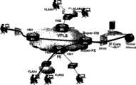
图1是VPLS的典型组网图,如图所示,CE(Custom Edge)设备所在接口加入VPLS VSI(虚拟交换实例,Virtual Switch Instance),PE(运营商边缘设备,Provider Edge)之间通过PW(伪连线,Pseudo Wire)互相连接,对客户形成一个仿真局域网,每个运营商边缘设备在虚拟交换实例内进行用户MAC地址学习(包括CE侧和PW侧),建立转发表项,使得加入相同虚拟交换实例的CE用户可以在二层进行互相访问。VPLS PW通常使用MPLS隧道,也可以使用其他任何隧道,如GRE、L2TPV3、TE等,其作用是完成以太网报文的透传。Figure 1 is a typical network diagram of VPLS. As shown in the figure, the interface where the CE (Custom Edge) device is located joins the VPLS VSI (Virtual Switch Instance, Virtual Switch Instance), and PEs (Provider Edge) pass through PW (pseudo wire, Pseudo Wire) are connected to each other to form a simulated local area network for customers, and each operator's edge device learns the user's MAC address (including the CE side and the PW side) in the virtual switching instance, and establishes a forwarding table entry, so that the joining CE users of the same virtual switching instance can access each other at Layer 2. VPLS PW usually uses MPLS tunnels, and can also use any other tunnels, such as GRE, L2TPV3, TE, etc., and its function is to complete the transparent transmission of Ethernet packets.
这里还需对QinQ(一种两层标签技术,802.1Q-in-802.1Q)技术进行简单介绍。QinQ又称VLAN-Stack,是一种对以太网报文进行两层VLAN TAG封装的技术,其总的思想都是将用户私网VLAN TAG封装在公网VLANTAG中,报文带着两层TAG穿越服务商的骨干网络,在服务商的骨干网络边缘剥离公网VLAN TAG,恢复用户私网VLAN TAG,从而为用户提供一种较为简单的二层VLAN TAG隧道。A brief introduction to QinQ (a two-layer label technology, 802.1Q-in-802.1Q) technology is also needed here. QinQ, also known as VLAN-Stack, is a technology for encapsulating Ethernet packets with two layers of VLAN TAG. Its general idea is to encapsulate the user's private network VLAN TAG in the public network VLAN TAG. Traversing the service provider's backbone network, stripping the public network VLAN TAG at the edge of the service provider's backbone network, and restoring the user's private network VLAN TAG, thus providing users with a relatively simple Layer 2 VLAN TAG tunnel.
在实际应用中,个人或企业用户可以通过虚拟专用局域网接入到远端接入认证设备BRAS(Broadband Remote Access Server,宽带接入服务器),访问Internet网络。个人或企业用户内部可以通过虚拟专用局域网在同一个虚拟交换实例内部进行二层访问,用户内部还可以划分VLAN(虚拟局域网)进行隔离,但是,因为不同用户之间不能互通,因此需要划分到不同的虚拟交换实例进行管理;同时,所有的用户可以访问同一个宽带接入服务器设备,宽带接入服务器设备可以为用户分配不同网段的IP地址,用户根据该IP地址接入到宽带接入服务器并且访问Internet网络。In practical applications, individual or enterprise users can access the remote access authentication device BRAS (Broadband Remote Access Server, Broadband Access Server) through a VPN to access the Internet. Individual or enterprise users can access Layer 2 within the same virtual switching instance through a virtual private area network. Users can also be divided into VLANs (virtual local area networks) for isolation. However, because different users cannot communicate with each other, they need to be divided into different At the same time, all users can access the same broadband access server device, and the broadband access server device can assign IP addresses of different network segments to users, and users can access the broadband access server according to the IP addresses And access to the Internet network.
如图2所示,属于同一虚拟交换实例(图中存在两个虚拟交换实例:VSI1和VSI2)的用户可以通过虚拟专用局域网互访,需要通过宽带接入服务器上网时,则需要在运营商边缘设备(PE)和宽带接入服务器设备(BRAS)上创建VLAN子接口,不同的子接口需要分别加入VSI1和VSI2,当用户数据携带用户VLAN时,PE设备到BRAS设备的用户数据成为QinQ报文(携带两层标签),宽带接入服务器需要终结该QinQ报文。As shown in Figure 2, users belonging to the same virtual switching instance (there are two virtual switching instances in the figure: VSI1 and VSI2) can access each other through a VPN. Create VLAN sub-interfaces on the device (PE) and broadband access server device (BRAS). Different sub-interfaces need to be added to VSI1 and VSI2 respectively. When user data carries user VLANs, the user data from the PE device to the BRAS device becomes a QinQ message. (carrying two layers of labels), the broadband access server needs to terminate the QinQ message.
因此,不同虚拟交换实例用户通过运营商边缘设备接入宽带接入服务器上网时,运营商边缘设备上要创建许多虚拟交换实例,并且运营商边缘设备与宽带接入服务器之间要创建许多子接口,不同子接口加入到不同虚拟交换实例,配置和管理都很复杂。Therefore, when users of different virtual switching instances access the broadband access server to surf the Internet through the carrier edge device, many virtual switching instances must be created on the carrier edge device, and many sub-interfaces must be created between the carrier edge device and the broadband access server , different sub-interfaces are added to different virtual switching instances, and the configuration and management are very complicated.
发明内容Contents of the invention
本发明的主要目的就是通过在虚拟专用局域网的运营商边缘设备上设置共享虚拟交换实例(Super-VSI),实现多个虚拟交换实例与一个共享虚拟交换实例进行互通,减小虚拟专用局域网接入到三层网络的配置和管理的复杂度。另外通过共享虚拟交换实例,实现不同虚拟交换实例用户在二层隔离,但可以方便地实现三层互访。The main purpose of the present invention is to realize intercommunication between multiple virtual switching instances and one shared virtual switching instance by setting a shared virtual switching instance (Super-VSI) on the operator's edge device of the virtual private local area network, and reduce the number of virtual private local area network access. to the complexity of the configuration and management of the three-tier network. In addition, by sharing virtual switching instances, users of different virtual switching instances are isolated at the second layer, but mutual access at the third layer can be easily realized.
本发明上述目的是这样实现的:The above-mentioned purpose of the present invention is achieved like this:
一种虚拟专用局域网的报文转发方法,包括步骤:在虚拟专用局域网中设置报文转发装置,该报文转发装置包括至少一个共享虚拟交换实例;配置所述共享虚拟交换实例的成员,该共享虚拟交换实例的成员为所述虚拟专用局域网中的多个不同的虚拟交换实例;当所述虚拟专用局域网中的用户经其所属的虚拟交换实例发送报文时,通过所述共享虚拟交换实例进行转发。A message forwarding method of a virtual private local area network, comprising the steps of: setting a message forwarding device in a virtual private local area network, the message forwarding device including at least one shared virtual exchange instance; configuring members of the shared virtual exchange instance, the shared The members of the virtual switching instance are a plurality of different virtual switching instances in the virtual private area network; when a user in the virtual private local area network sends a message through the virtual switching instance to which it belongs, it is performed through the shared virtual switching instance Forward.
其中,当所述虚拟专用局域网中的用户请求认证上网时,包括步骤:所述报文转发装置接收到用户发送的接入请求报文,检查所述用户所属的虚拟交换实例是否是所述共享虚拟交换实例的成员;如果检查结果为是,则该报文转发装置在所述共享虚拟交换实例及其所有的成员中查找MAC转发表项,找到相应出接口发送所述请求报文。Wherein, when a user in the virtual private local area network requests authentication to access the Internet, the steps include: the message forwarding device receives an access request message sent by the user, and checks whether the virtual switching instance to which the user belongs is the shared member of the virtual switching instance; if the check result is yes, then the message forwarding device searches the MAC forwarding entry in the shared virtual switching instance and all its members, and finds the corresponding outbound interface to send the request message.
其中,所述出接口为该报文转发装置与接入服务器相连的接口,所述请求报文通过该接口转发给该接入服务器连接上网。Wherein, the outgoing interface is an interface connecting the message forwarding device to the access server, and the request message is forwarded to the access server through the interface to connect to the Internet.
其中,如果所述转发表项是首包或者转发表项未找到,则包括下列步骤:所述报文转发装置在所述共享虚拟交换实例及除发送报文的用户所属的虚拟交换实例外的所有成员虚拟交换实例对应的接口内发送所述请求报文,同时进行MAC地址学习。Wherein, if the forwarding table item is the first packet or the forwarding table item is not found, the following steps are included: the message forwarding device is in the shared virtual switching instance and other than the virtual switching instance to which the user sending the message belongs. The interface corresponding to all member virtual switching instances sends the request message and learns the MAC address at the same time.
此外,本发明的方法还包括下列步骤:在报文转发装置上设置至少一个与共享虚拟交换实例相关的三层逻辑接口,并配置与成员虚拟交换实例的用户的IP地址属于同一网段的IP地址及配置MAC地址。In addition, the method of the present invention also includes the following steps: setting at least one layer-3 logical interface related to the shared virtual switching instance on the message forwarding device, and configuring the IP address belonging to the same network segment as the IP address of the user of the member virtual switching instance. address and configure the MAC address.
其中,当所述虚拟专用局域网中的用户请求进行三层访问时,包括步骤:报文转发装置接收到用户发送的arp请求报文,检查目的IP地址是否是要代理的IP地址,如果是,则查找目的用户MAC地址,回送包含有三层逻辑接口的MAC地址的arp响应消息。Wherein, when the user request in the virtual private local area network is carried out three layers of visits, comprises the step: the message forwarding device receives the arp request message that the user sends, checks whether the destination IP address is the IP address that will be proxied, if yes, Then search for the MAC address of the destination user, and send back an arp response message containing the MAC address of the three-layer logical interface.
其中,所述查找目的用户MAC地址的步骤包括:报文转发装置在所述共享虚拟交换实例及其配置的成员内查找。当所述MAC地址不存在时,则报文转发装置发送arp请求消息到所述共享虚拟交换实例及成员虚拟交换实例进行查找。Wherein, the step of finding the MAC address of the destination user includes: the message forwarding device searches in the shared virtual switching instance and its configured members. When the MAC address does not exist, the message forwarding device sends an arp request message to the shared virtual switching instance and member virtual switching instance to search.
其中,如果目的IP地址不是要代理的IP地址,则检查该目的IP地址是否是三层逻辑接口的IP地址,如果是,则回送包含有三层逻辑接口的MAC地址的arp响应消息。Wherein, if the destination IP address is not the IP address to be proxied, check whether the destination IP address is the IP address of the three-layer logical interface, and if so, send back an arp response message comprising the MAC address of the three-layer logical interface.
另外,上述方法还包括下列步骤:请求用户发送数据报文到报文转发装置,报文转发装置将所述数据报文上送到三层逻辑接口,查找路由表进行转发。In addition, the above method also includes the following steps: requesting the user to send the data message to the message forwarding device, and the message forwarding device sends the data message to the three-layer logical interface, and searches the routing table for forwarding.
其中,如果目的IP地址为代理的IP地址,则该报文转发装置根据查找到的目的用户MAC地址通过所述三层逻辑接口将数据报文发送到目的用户,如此即实现了虚拟专用局域网的不同虚拟交换实例的用户的二层隔离、三层互访。Wherein, if the destination IP address is the IP address of the proxy, the message forwarding device sends the data message to the destination user through the three-layer logical interface according to the destination user MAC address found, thus realizing the virtual private local area network Layer 2 isolation and Layer 3 mutual access of users of different virtual switching instances.
其中,如果目的IP地址为三层逻辑接口的IP地址,则该报文转发装置将数据报文通过该三层逻辑接口发送到三层网络,如此即实现了虚拟专用局域网的用户访问三层网络。Wherein, if the destination IP address is the IP address of the three-layer logical interface, the message forwarding device sends the data message to the three-layer network through the three-layer logical interface, so that the user of the virtual private local area network can access the three-layer network .
一种虚拟专用局域网的报文转发装置,包括:至少一个共享虚拟交换实例,配置有多个成员,该共享虚拟交换实例的成员为所述虚拟专用局域网中的多个不同的虚拟交换实例,其中,当所述虚拟专用局域网中的用户经其所属的虚拟交换实例发送报文时,通过所述共享虚拟交换实例进行转发。A message forwarding device for a virtual private local area network, comprising: at least one shared virtual switching instance configured with multiple members, the members of the shared virtual switching instance being a plurality of different virtual switching instances in the virtual private local area network, wherein , when a user in the virtual private local area network sends a message through the virtual switching instance to which it belongs, the packet is forwarded through the shared virtual switching instance.
其中,上述报文转发装置还包括:与一接入服务器相连的接口,用于转发所述虚拟专用局域网的用户的请求报文。Wherein, the above-mentioned message forwarding device further includes: an interface connected to an access server, for forwarding the request message of the user of the virtual private local area network.
所述接口为QinQ接口或普通接口;当接口为QinQ接口时,在该接口上配置有虚拟交换实例到外层标签的对应关系;当接口为普通接口时,在该接口上配置有不带虚拟局域网的虚拟交换实例用户报文的缺省外层标签。The interface is a QinQ interface or a common interface; when the interface is a QinQ interface, the interface is configured with a virtual exchange instance to the outer label correspondence; when the interface is a common interface, the interface is configured with no The default outer label of user packets of the virtual switching instance in the LAN.
其中,上述报文转发装置还包括:arp代理单元,用于根据所述虚拟专用局域网的不同虚拟交换实例的用户的arp请求报文查找目的用户MAC地址。Wherein, the message forwarding device further includes: an arp proxy unit, configured to search for the MAC address of the destination user according to the arp request messages of users of different virtual switching instances of the virtual private local area network.
其中,上述报文转发装置还包括:至少一个三层逻辑接口,配置有与所述虚拟专用局域网的请求用户属于同一网段的IP地址及MAC地址,用于虚拟专用局域网的用户进行三层访问。Wherein, the above-mentioned message forwarding device also includes: at least one layer-3 logical interface, configured with an IP address and a MAC address belonging to the same network segment as the requesting user of the virtual private local area network, for the user of the virtual private local area network to perform layer-3 access .
本发明的有益效果为:The beneficial effects of the present invention are:
1、实现虚拟专用局域网中多个虚拟交换实例进行共享或聚合使用,减小配置和管理的复杂性;1. Realize the sharing or aggregation of multiple virtual switching instances in the virtual private LAN, reducing the complexity of configuration and management;
2、共享虚拟交换实例可以实现不同虚拟交换实例内的二层隔离,但可以进行三层互访,其应用如基于安全的考虑,防止虚拟交换实例之间的二层攻击行为,但可以通过报文转发装置统一控制不同虚拟交换实例用户能否互访;2. Shared virtual switching instances can achieve Layer 2 isolation in different virtual switching instances, but Layer 3 mutual access is possible. For example, based on security considerations, it can prevent Layer 2 attacks between virtual switching instances, but it can be reported through The file forwarding device uniformly controls whether users of different virtual exchange instances can access each other;
3、通过虚拟交换实例接口(VSI-interface),即三层逻辑接口实现虚拟专用局域网接入到三层网络,解决了如果接入时不通过共享虚拟交换实例的方式,对每个虚拟交换实例都建立一个相关的三层逻辑接口,并且配置IP地址,会消耗大量IP地址的问题。3. Through the virtual switching instance interface (VSI-interface), that is, the three-layer logical interface, the virtual private local area network is connected to the three-layer network, which solves the problem that if the access is not shared by the virtual switching instance, each virtual switching instance Both establish a related layer-3 logical interface and configure IP addresses, which will consume a large number of IP addresses.
附图说明Description of drawings
图1是现有技术中虚拟专用局域网典型的组网图;Fig. 1 is a typical networking diagram of a virtual private local area network in the prior art;
图2是现有技术中用户通过虚拟专用局域网接入到宽带接入服务器上网的示意图;FIG. 2 is a schematic diagram of a user accessing a broadband access server to access the Internet through a virtual private local area network in the prior art;
图3是利用本发明,用户通过虚拟专用局域网接入到宽带接入服务器上网的示意图;Fig. 3 is a schematic diagram of using the present invention to access the broadband access server to the Internet through a virtual private local area network;
图4是利用本发明,不同虚拟交换实例用户通过虚拟专用局域网和共享虚拟交换实例实现三层访问的示意图。Fig. 4 is a schematic diagram of layer 3 access implemented by users of different virtual switching instances through a virtual private local area network and a shared virtual switching instance by using the present invention.
具体实施方式Detailed ways
本发明的核心内容是,通过在虚拟专用局域网的报文转发装置上(例如运营商边缘设备PE)设置共享虚拟交换实例,实现多个虚拟交换实例与一个共享虚拟交换实例进行互通,减小虚拟专用局域网接入到三层网络的配置和管理的复杂度;另外通过在设置有共享虚拟交换实例的报文转发装置上启动arp代理功能及设置三层逻辑接口,实现不同虚拟交换实例用户在二层隔离、三层访问。The core content of the present invention is that, by setting a shared virtual switching instance on the message forwarding device of the virtual private area network (for example, the operator's edge equipment PE), the intercommunication between multiple virtual switching instances and one shared virtual switching instance is realized, reducing the number of virtual switching instances. The configuration and management complexity of accessing the private LAN to the three-layer network; in addition, by starting the arp proxy function and setting the three-layer logical interface on the message forwarding device with the shared virtual switching instance, users of different virtual switching instances can be connected to each other Layer isolation, three-layer access.
下面结合附图和实施例对本发明进行详细说明。The present invention will be described in detail below in conjunction with the accompanying drawings and embodiments.
本发明提供的虚拟专用局域网的报文转发方法主要包括下列步骤:在虚拟专用局域网中设置报文转发装置,该报文转发装置包括至少一个共享虚拟交换实例;配置所述共享虚拟交换实例的成员,该成员虚拟交换实例为所述虚拟专用局域网中的多个虚拟交换实例;当所述虚拟专用局域网中的用户经其所属的虚拟交换实例发送报文时,通过所述共享虚拟交换实例进行转发。The message forwarding method of the virtual private local area network provided by the present invention mainly includes the following steps: a message forwarding device is set in the virtual private local area network, and the message forwarding device includes at least one shared virtual exchange instance; members of the shared virtual exchange instance are configured , the member virtual switching instance is a plurality of virtual switching instances in the virtual private area network; when a user in the virtual private local area network sends a message through the virtual switching instance to which it belongs, it is forwarded through the shared virtual switching instance .
下面以所述报文转发装置为该虚拟专用局域网中的运营商边缘设备为例进行说明,本发明所说的共享虚拟交换实例就是可以共享多个虚拟交换实例的一个超级VSI实例,我们称之为Super-VSI,该Super-VSI设置于报文转发装置上,即运营商边缘设备PE上,为了方便说明,这里将设置有Super-VSI的报文转发装置称为Super-PE。In the following, the message forwarding device is taken as an example of an operator edge device in the virtual private local area network. The shared virtual switching instance in the present invention is a super VSI instance that can share multiple virtual switching instances, which we call It is a Super-VSI, and the Super-VSI is set on the message forwarding device, that is, the operator edge equipment PE. For the convenience of description, the message forwarding device equipped with the Super-VSI is called Super-PE here.
接下来,为所述共享虚拟交换实例配置多个成员,称为成员虚拟交换实例(Sub-VSI),该成员即为所述虚拟专用局域网中的多个虚拟交换实例,可以将该虚拟专用局域网中的所有虚拟交换实例配置为共享虚拟交换实例的成员,也可以仅配置一部分。至于配置的方法,在本发明中不作限制,只要建立起Super-VSI与Sub-VSI的共享关系,使得在该虚拟专用局域网中,所有的成员虚拟交换实例都可以与共享虚拟交换实例进行互通即可。Next, configure multiple members for the shared virtual switching instance, which is called a member virtual switching instance (Sub-VSI). All virtual switching instances in a configuration are configured as members of a shared virtual switching instance, or only a subset of them can be configured. As for the configuration method, it is not limited in the present invention, as long as the sharing relationship between Super-VSI and Sub-VSI is established, so that in the virtual private local area network, all member virtual switching instances can communicate with the shared virtual switching instance. Can.
根据上述设置,当所述虚拟专用局域网中的用户发送请求时,即可通过所述报文转发装置,进一步说,通过所述共享虚拟交换实例进行转发。下面根据用户的请求不同,结合附图分别进行说明。According to the above settings, when a user in the virtual private area network sends a request, it can be forwarded through the packet forwarding device, more specifically, through the shared virtual switching instance. In the following, descriptions will be made respectively in conjunction with the accompanying drawings according to different requests of users.
范例一、虚拟专用局域网的用户请求认证上网:Example 1: A VPN user requests authentication to access the Internet:
图3为利用Super-VSI实现虚拟专用局域网用户通过宽带接入服务器上网的示意图。如图所示,Super-PE是虚拟专用局域网与宽带接入服务器相连的边缘设备,在Super-PE上配置Super-VSI,Super-VSI包含虚拟专用局域网中的VSI1和VSI2作为其成员虚拟交换实例,这里并不限定于此,可以包含所有的虚拟交换实例,此处仅以Super-VSI包括VSI1和VSI2为例进行说明,与宽带接入服务器相连的Super-PE上的接口加入到Super-VSI,这样VSI1和VSI2的用户都可以将报文发送到Super-PE的Super-VSI,并且转发给宽带接入服务器进行认证和上网。FIG. 3 is a schematic diagram of using the Super-VSI to realize that a virtual private area network user accesses the Internet through a broadband access server. As shown in the figure, Super-PE is an edge device connecting a virtual private area network to a broadband access server. Super-VSI is configured on Super-PE, and Super-VSI includes VSI1 and VSI2 in the virtual private area network as its member virtual switching instances , this is not limited to this, and can include all virtual switching instances. Here, only Super-VSI including VSI1 and VSI2 is used as an example for illustration. The interface on the Super-PE connected to the broadband access server is added to the Super-VSI , so that the users of VSI1 and VSI2 can send the packets to the Super-VSI of the Super-PE, and forward them to the broadband access server for authentication and Internet access.
因为不同客户端的用户通过虚拟交换实例连接认证接入服务器上网是现有技术的内容,而本发明只是以一个共享虚拟交换实例,即Super-VSI替代现有技术中与宽带接入服务器连接的虚拟交换实例而实现认证上网,因此,具体的接入过程在这里不再赘述。Because it is the content of the prior art that users of different clients connect to the authentication access server to access the Internet through a virtual exchange instance, but the present invention only uses a shared virtual exchange instance, i.e. Super-VSI, to replace the virtual server connected to the broadband access server in the prior art. Exchanging instances realizes authentication and access to the Internet. Therefore, the specific access process will not be repeated here.
注意,为了宽带接入服务器能区分不同的虚拟交换实例的用户,可以将与宽带接入服务器相连的Super-PE接口设为QinQ接口,不同虚拟交换实例的用户报文映射到不同的外层VLAN,宽带接入服务器进行QinQ终结并区分用户,注:可以区分到用户的不同VLAN。Note that in order for the broadband access server to distinguish users of different virtual switching instances, the Super-PE interface connected to the broadband access server can be set as a QinQ interface, and user packets of different virtual switching instances are mapped to different outer VLANs , the broadband access server performs QinQ termination and distinguishes users. Note: Different VLANs of users can be distinguished.
一种特殊情况是,在Super-VSI处理时,对于从其它虚拟交换实例,即不属于Super-VSI的成员虚拟交换实例发来的所有不带VLAN的数据统一使用缺省的VLAN标签进行QinQ封装。而当网络规划中不允许用户VLAN通过虚拟专用局域网发送时,Super-PE与宽带接入服务器的接口就是普通物理接口。A special case is that during Super-VSI processing, all data without VLANs sent from other virtual switching instances, that is, member virtual switching instances that do not belong to the Super-VSI, are uniformly encapsulated with the default VLAN tag for QinQ encapsulation. . And when the network planning does not allow the user VLAN to be sent through the virtual private area network, the interface between the Super-PE and the broadband access server is a common physical interface.
具体的实现方法为:The specific implementation method is:
步骤1:在Super-PE上配置Super-VSI,并且配置Super-VSI的成员Sub-VSI,在本实施例中,假设配置了VSI1和VSI2作为其成员虚拟交换实例;Step 1: Configure Super-VSI on the Super-PE, and configure the member Sub-VSI of Super-VSI. In this embodiment, it is assumed that VSI1 and VSI2 are configured as its member virtual switching instances;
步骤2:建立PE1、PE2和Super-PE的虚拟专用局域网的相关元素,这里,可以为该虚拟专用局域网中的全部PE,而不限于PE1、PE2,例如可以包括PE3,在此,仅以PE1和PE2为例进行说明;该过程具体包括建立相互的VPLS PW隧道,PE1、PE2上与用户PC1、PC2相关的接口加入到相应的VSI等,这个过程是VPLS的既有处理流程,在此不再赘述;Step 2: Establish the relevant elements of the virtual private area network of PE1, PE2 and Super-PE. Here, it can be all PEs in the virtual private area network, not limited to PE1 and PE2. For example, it can include PE3. Here, only PE1 Take PE2 as an example for illustration; this process specifically includes establishing mutual VPLS PW tunnels, and adding the interfaces related to user PC1 and PC2 on PE1 and PE2 to the corresponding VSI, etc. repeat;
步骤3:用户PC2发送认证请求报文经该用户所属的虚拟交换实例VSI2发送到所述报文转发装置Super-PE;Step 3: The user PC2 sends an authentication request message to the message forwarding device Super-PE via the virtual switching instance VSI2 to which the user belongs;
步骤4:将与宽带接入服务器相连的接口加入到Super-VSI,根据需要,将接口类型配置为QinQ接口或普通接口,对于QinQ接口,需要配置VSI到外层标签的对应关系,另外还可以根据需要配置不带VLAN的VSI用户报文的缺省外层标签;Step 4: Add the interface connected to the broadband access server to the Super-VSI, and configure the interface type as QinQ interface or common interface as required. For the QinQ interface, you need to configure the corresponding relationship between the VSI and the outer label. Configure the default outer label of VSI user packets without VLAN as required;
步骤5:当Super-PE收到虚拟专用局域网的用户PC2发送的认证请求报文后,检查其所属VSI2是否是Super-VSI的成员,如果是,则在该报文转发装置的Super-VSI及其配置的所有成员Sub-VSI(VSI1和VSI2)内查找MAC转发表项,找到相应出接口进行发送,在本实施例中,即为与接入服务器相连的接口;Step 5: After the Super-PE receives the authentication request message sent by the user PC2 of the virtual private area network, it checks whether its VSI2 is a member of the Super-VSI. All member Sub-VSIs (VSI1 and VSI2) of its configuration search the MAC forwarding table entry, find the corresponding outgoing interface and send it, in this embodiment, it is the interface connected with the access server;
如果出接口为QinQ接口,则所述请求报文使用缺省的虚拟局域网标签进行QinQ封装,再进行转发。If the outbound interface is a QinQ interface, the request message is encapsulated by QinQ using the default virtual local area network label, and then forwarded.
如果所述报文是首包或者转发表项未找到,则在Super-VSI及所有成员Sub-VSI对应的接口(包括PW,但去掉接收报文的那个接口)内发送;另外,还要在所属虚拟交换实例范围进行MAC地址学习,保存相关信息,这个过程也是虚拟专用局域网的既有处理流程,在此不再赘述。If the message is the first packet or the forwarding table entry is not found, it will be sent in the interfaces corresponding to the Super-VSI and all member Sub-VSIs (including the PW, but the interface that receives the message is removed); The scope of the virtual switching instance to which it belongs performs MAC address learning and saves relevant information. This process is also an existing processing flow of the virtual private area network, and will not be repeated here.
本实施例将配置有Super-VSI的Super-PE与接入服务器,如宽带接入服务器(BRAS,Broadband Remote Access Server)相连的接口加入Super-VSI,并根据需要将接口类型配置为QinQ接口或普通接口。对于QinQ接口,需要配置VSI到外层标签的对应关系。对于普通接口,则可以配置不带VLAN的VSI用户报文的缺省外层标签。如此一来,VPLS网络不同虚拟交换实例的用户即可通过该Super-VSI实现轻松接入到BRAS而上网。In this embodiment, the Super-PE configured with Super-VSI is connected to the access server, such as a broadband access server (BRAS, Broadband Remote Access Server) The interface connected to the Super-VSI is added, and the interface type is configured as a QinQ interface or as required. common interface. For QinQ interfaces, you need to configure the correspondence between VSIs and outer labels. For common interfaces, you can configure the default outer label of VSI user packets without VLAN. In this way, users of different virtual switching instances in the VPLS network can easily access the BRAS and surf the Internet through the Super-VSI.
范例二、虚拟专用局域网中不同虚拟交换实例的用户请求互访:Example 2: Users requesting mutual visits of different virtual switching instances in a VPN:
本实施例是当不同虚拟交换实例的用户需要进行三层互访时,在报文转发装置,也即本实施例中的Super-PE处启动arp代理功能。In this embodiment, when users of different virtual switching instances need to perform layer-3 mutual access, the arp proxy function is started at the message forwarding device, that is, the Super-PE in this embodiment.
arp代理功能是指对被其隔离的不同广播域内的arp请求报文进行代理应答的过程,在本发明中,该arp代理功能需实现对Super-VSI的所有成员Sub-VSI内的用户进行代理,要求用户发送报文到本地,即该报文转发装置处,由本地进行转发。The arp proxy function refers to the process of performing proxy responses to the arp request messages in the different broadcast domains isolated by it. In the present invention, the arp proxy function needs to be implemented to act as a proxy for users in all members of the Super-VSI Sub-VSI , the user is required to send the message to the local, that is, the message forwarding device, and the message is forwarded locally.
如图4所示,正常情况下,VSI1和VSI2的用户不能互相访问,例如图中的PC1和PC2,IP地址分别为IP1和IP2,属于同一网段,PC1发出的arp请求报文不能到达PC2,因此PC1不会收到PC2的arp响应消息,因此就不能获取PC2的MAC地址,因此PC1不能向PC2发出IP报文。As shown in Figure 4, under normal circumstances, users of VSI1 and VSI2 cannot access each other. For example, PC1 and PC2 in the figure have IP addresses IP1 and IP2, and they belong to the same network segment. The arp request message sent by PC1 cannot reach PC2. , so PC1 will not receive the arp response message from PC2, and therefore cannot obtain the MAC address of PC2, so PC1 cannot send IP packets to PC2.
当在Super-PE处配置Super-VSI时,同时配置与Super-VSI相关的三层逻辑接口,并配置该三层逻辑接口的IP地址和MAC地址,其中Super-VSI的成员包括VSI1和VSI2,此时PC1的arp请求报文(广播报文)可以发送到Super-PE,Super-PE启动arp代理功能,当检查到PC1的IP地址为其代理的IP地址时,则在Super-VSI的范围内(即VSI1和VSI2)发送arp请求消息查找PC2的MAC地址,该arp请求消息将通过PE2发送给PC2,PC2回送arp响应消息给Super-PE,然后Super-PE通过arp代理功能向PC1回送arp响应消息,告知“PC2的MAC地址”,请注意,此时,Super-PE告诉PC1的MAC地址并非是真正的PC2的MAC地址,而是三层逻辑接口的MAC地址,如此即完成了二层隔离,随后PC1向PC2发送IP数据报文,该IP数据报文将被本地收到并送到三层逻辑接口处理,通过查路由表转发到PC2,PC1和PC2实现了三层访问。When configuring Super-VSI at the Super-PE, configure the Layer 3 logical interface related to Super-VSI at the same time, and configure the IP address and MAC address of the Layer 3 logical interface. The members of Super-VSI include VSI1 and VSI2. At this time, the arp request message (broadcast message) of PC1 can be sent to Super-PE, and Super-PE starts the arp proxy function. Internally (that is, VSI1 and VSI2) send an arp request message to find the MAC address of PC2. The arp request message will be sent to PC2 through PE2, and PC2 will send back an arp response message to Super-PE, and then Super-PE will send back arp to PC1 through the arp proxy function. Respond to the message and inform "PC2's MAC address". Please note that at this time, the MAC address told by Super-PE to PC1 is not the real MAC address of PC2, but the MAC address of the three-layer logical interface, thus completing the two-layer After isolation, PC1 sends an IP data packet to PC2. The IP data packet will be received locally and sent to the layer-3 logical interface for processing, and forwarded to PC2 by checking the routing table. PC1 and PC2 realize layer-3 access.
具体的实现方法为:The specific implementation method is:
步骤1:在Super-PE上配置Super-VSI,并且配置Super-VSI的成员Sub-VSI,在本实施例中,假设配置了VSI1和VSI2作为其成员虚拟交换实例;Step 1: Configure Super-VSI on the Super-PE, and configure the member Sub-VSI of Super-VSI. In this embodiment, it is assumed that VSI1 and VSI2 are configured as its member virtual switching instances;
步骤2:设置与Super-VSI相关的至少一个三层逻辑接口,并配置该三层逻辑接口的IP地址和MAC地址;Step 2: Set at least one layer-3 logical interface related to Super-VSI, and configure the IP address and MAC address of the layer-3 logical interface;
步骤3:建立PE1、PE2和Super-PE的虚拟专用局域网的相关元素,这里,可以为该虚拟专用局域网中的全部PE,而不限于PE1、PE2,例如可以包括PE3,在此,仅以PE1和PE2为例进行说明;该过程具体包括建立相互的VPLS PW隧道,PE1、PE2上与用户PC1、PC2相关的接口加入到相应的VSI等,这个过程是VPLS的既有处理流程,在此不再赘述;Step 3: Establish the relevant elements of the virtual private area network of PE1, PE2 and Super-PE. Here, it can be all PEs in the virtual private area network, not limited to PE1 and PE2. For example, it can include PE3. Here, only PE1 Take PE2 as an example for illustration; this process specifically includes establishing mutual VPLS PW tunnels, and adding the interfaces related to user PC1 and PC2 on PE1 and PE2 to the corresponding VSI, etc. repeat;
步骤4:虚拟专用局域网的用户PC1发送arp请求报文要求访问PC2,其中,PC1属于PE1处的VSI1,其IP地址为IP1,PC2属于PE2处的VSI2,其IP地址为IP2,所述arp请求报文经该用户PC1所属的虚拟交换实例VSI1发送到所述报文转发装置Super-PE;Step 4: User PC1 of the virtual private area network sends an arp request message to request access to PC2, wherein PC1 belongs to VSI1 at PE1, and its IP address is IP1, and PC2 belongs to VSI2 at PE2, and its IP address is IP2, and the arp request The message is sent to the message forwarding device Super-PE via the virtual switching instance VSI1 to which the user PC1 belongs;
步骤5:所述报文转发装置Super-PE检查所述用户PC2,即目的用户的IP地址是否是其代理的IP地址,即是否是成员虚拟交换实例的用户的IP地址,如果是,则进行后续步骤;Step 5: The message forwarding device Super-PE checks the user PC2, that is, whether the IP address of the destination user is the IP address of its agent, that is, whether it is the IP address of the user of the member virtual switching instance, and if so, proceed next steps;
步骤6:Super-PE执行arp代理功能,该arp代理功能需实现对Super-VSI的所有成员Sub-VSI内的用户进行代理,所述报文转发装置Super-PE检查所述arp请求报文中目的用户PC2的IP地址对应的MAC地址,该过程可以通过在该共享虚拟交换实例及其配置的成员内进行查找,如果没有查到,则发送arp请求消息到所述共享虚拟交换实例Super-VSI及其所有的成员Sub-VSI(可以除了请求用户)进行查找;Step 6: Super-PE executes the arp proxy function, and the arp proxy function needs to implement proxying to users in all member Sub-VSIs of the Super-VSI, and the message forwarding device Super-PE checks the arp request message The MAC address corresponding to the IP address of the destination user PC2 can be searched in the shared virtual switching instance and its configured members. If not found, an arp request message is sent to the shared virtual switching instance Super-VSI and all of its member Sub-VSIs (except requesting users);
步骤7:Super-PE向PC1回送arp响应消息,告知其PC2的MAC地址,这里,该MAC地址实际为三层逻辑接口的MAC地址;Step 7: The Super-PE sends an arp response message back to PC1, informing it of the MAC address of PC2. Here, the MAC address is actually the MAC address of the Layer 3 logical interface;
步骤8:PC1发送数据报文到Super-PE,Super-PE将该数据报文上送到三层逻辑接口,再通过查找路由表转发到PC2。Step 8: PC1 sends the data packet to the Super-PE, and the Super-PE sends the data packet to the Layer 3 logical interface, and then forwards the data packet to PC2 by looking up the routing table.
在现有技术中,不同虚拟交换实例的用户在二层是隔离的,其互相之间不能进行三层互访,而利用本发明,进一步说,利用本发明设置的共享虚拟交换实例Super-VSI,即可方便地实现虚拟专用局域网中不同虚拟交换实例的用户在二层相互隔离,但在三层互相访问。In the prior art, users of different virtual exchange instances are isolated on the second floor, and they cannot perform mutual visits on the third floor. However, with the present invention, further speaking, the shared virtual exchange instance Super-VSI set by the present invention , users of different virtual switching instances in the virtual private area network can be easily isolated from each other at the second layer, but they can access each other at the third layer.
范例三、虚拟专用局域网中的用户请求接入到三层网络:Example 3: A user in a VPN requests access to a Layer 3 network:
本范例与范例二类似,都是在三层进行访问,不同之处在于,报文转发装置在检查到目的用户IP地址为三层逻辑接口的IP地址时,直接回送arp响应消息,请求用户再发送数据报文时,则直接上送到三层逻辑接口通过查找路由表进行转发。This example is similar to Example 2, both of which access at Layer 3. The difference is that when the packet forwarding device detects that the IP address of the destination user is the IP address of a Layer 3 logical interface, it directly returns an arp response message, requesting the user to When sending a data packet, it is directly sent to the layer-3 logical interface for forwarding by looking up the routing table.
如图4所示,图中Super-PE设备右侧是IP网,左侧是虚拟专用局域网,虚拟专用局域网内不同虚拟交换实例的用户(例如为PC1和PC2)要访问IP网络中的用户时,可以在报文转发装置上创建三层逻辑接口(可称为VSI-interface),然后在VSI-interface上配置IP地址,该IP地址与IP1和IP2属于同一网段,这样PC1、PC2就可以访问三层IP网络中的用户了。As shown in Figure 4, the right side of the Super-PE device in the figure is the IP network, and the left side is the virtual private area network. Users of different virtual switching instances in the virtual private area network (for example, PC1 and PC2) want to access users in the IP network , you can create a layer-3 logical interface (called a VSI-interface) on the message forwarding device, and then configure an IP address on the VSI-interface, which belongs to the same network segment as IP1 and IP2, so that PC1 and PC2 can Access to users in the three-layer IP network.
具体的实现方法为:The specific implementation method is:
步骤1:在Super-PE上配置Super-VSI,并且配置Super-VSI的成员Sub-VSI,在本实施例中,假设配置了VSI1和VSI2作为其成员虚拟交换实例;Step 1: Configure Super-VSI on the Super-PE, and configure the member Sub-VSI of Super-VSI. In this embodiment, it is assumed that VSI1 and VSI2 are configured as its member virtual switching instances;
步骤2:建立PE1、PE2和Super-PE的虚拟专用局域网的相关元素,这里,可以为该虚拟专用局域网中的全部PE,而不限于PE1、PE2,例如可以包括PE3,在此,仅以PE1和PE2为例进行说明;该过程具体包括建立相互的VPLS PW隧道,PE1、PE2上与用户PC1、PC2相关的接口加入到相应的VSI等,这个过程是VPLS的既有处理流程,在此不再赘述;Step 2: Establish the relevant elements of the virtual private area network of PE1, PE2 and Super-PE. Here, it can be all PEs in the virtual private area network, not limited to PE1 and PE2. For example, it can include PE3. Here, only PE1 Take PE2 as an example for illustration; this process specifically includes establishing mutual VPLS PW tunnels, and adding the interfaces related to user PC1 and PC2 on PE1 and PE2 to the corresponding VSI, etc. repeat;
步骤3:在报文转发装置上设置至少一个与Super-VSI相关的三层逻辑接口VSI-interface,在所述三层逻辑接口上配置与Sub-VSI用户的IP地址属于同一网段的IP地址以及配置MAC地址;另外Super-PE要实现路由功能,即可以通过目的地址如IP1找到其出接口为VSI-interface;Step 3: Set at least one layer-3 logical interface VSI-interface related to the Super-VSI on the message forwarding device, and configure an IP address belonging to the same network segment as the IP address of the Sub-VSI user on the layer-3 logical interface And configure the MAC address; in addition, the Super-PE needs to implement the routing function, that is, it can find out that its outgoing interface is VSI-interface through the destination address such as IP1;
步骤4:虚拟专用局域网的用户,例如PC1发送数据报文经该用户所属的虚拟交换实例VSI1发送到所述报文转发装置Super-PE;该报文转发装置Super-PE判断所述报文目的MAC地址是否为上述三层逻辑接口的MAC地址;如果判断结果为是,则该报文转发装置将所述接入请求报文上送三层处理,查找路由表进行转发;Step 4: A user of a virtual private local area network, such as PC1, sends a data message to the message forwarding device Super-PE through the virtual switching instance VSI1 to which the user belongs; the message forwarding device Super-PE determines the purpose of the message Whether the MAC address is the MAC address of the above-mentioned three-layer logical interface; if the judgment result is yes, then the message forwarding device will send the access request message to the three-layer processing, and search the routing table for forwarding;
当出接口为三层逻辑接口时,报文转发装置Super-PE在Super-VSI和所有成员Sub-VSI范围内查找目的IP对应的MAC地址并且通过相应的VSI发送消息;当所述MAC地址不存在时,报文转发装置Super-PE发送arp请求报文到所述共享虚拟实例Super-VSI及其成员Sub-VSI,以查找所述MAC地址。When the outgoing interface is a layer-3 logical interface, the packet forwarding device Super-PE searches for the MAC address corresponding to the destination IP within the scope of the Super-VSI and all member Sub-VSIs and sends a message through the corresponding VSI; If it exists, the message forwarding device Super-PE sends an arp request message to the shared virtual instance Super-VSI and its member Sub-VSI to find the MAC address.
本范例通过在Super-PE上创建Super-VSI相关的三层逻辑接口VSI-interface,并在该接口上配置与所有Sub-VSI用户的IP地址属于同一网段的IP地址以及设置MAC地址,即可实现该虚拟专用局域网通过Super-VSI接入到三层网络。此时,Super-PE要实现路由功能,就可以通过目的地址找到其出接口VSI-interface。This example creates a Super-VSI-related Layer 3 logical interface VSI-interface on the Super-PE, and configures an IP address on the same network segment as the IP addresses of all Sub-VSI users and sets a MAC address on the interface, that is, The Virtual Private LAN can be connected to the Layer 3 network through the Super-VSI. At this time, if the Super-PE needs to implement the routing function, it can find its outgoing interface VSI-interface through the destination address.
这里需要说明的是,本发明的虚拟专用局域网可以在报文转发装置,例如运营商边缘设备上创建多个Super-VSI和多个VSI-interface,在单个Super-VSI和VSI-interface内应用上述规则,不同VSI-interface之间的访问则按照正常的三层接口的访问来处理,即进行一般的路由转发。What needs to be explained here is that the virtual private local area network of the present invention can create multiple Super-VSIs and multiple VSI-interfaces on a message forwarding device, such as an operator's edge device, and apply the above-mentioned According to the rules, the access between different VSI-interfaces is handled according to the normal layer-3 interface access, that is, general routing and forwarding is performed.
根据以上的说明可知,本发明另提供一种虚拟专用局域网的报文转发系统及报文转发装置,所述系统包括:多个客户端,该多个客户端可以分布于不同的地理位置,也可以位于同一地理位置,在每一个地理位置,所述客户端都通过至少一个运营商边缘设备连接虚拟专用局域网;至少一个报文转发装置,在本发明的实施例中为Super-PE,该报文转发装置包括至少一个共享虚拟交换实例Super-VSI,用于转发所述虚拟专用局域网中的用户请求报文,其中,所述共享虚拟交换实例Super-VSI配置有多个成员,该成员为所述虚拟专用局域网中的为区分不同用户的多个虚拟交换实例,用于与所述共享虚拟交换实例互通,在本实施例中为VSI1和VSI2。According to the above description, it can be seen that the present invention further provides a message forwarding system and a message forwarding device of a virtual private local area network. The system includes: multiple clients, the multiple clients can be distributed in different geographic locations, Can be located in the same geographic location, in each geographic location, the client is connected to the virtual private local area network through at least one operator edge device; at least one message forwarding device, in the embodiment of the present invention is Super-PE, the report The document forwarding device includes at least one shared virtual switching instance Super-VSI, which is used to forward the user request message in the virtual private local area network, wherein the shared virtual switching instance Super-VSI is configured with multiple members, and the members are all Multiple virtual switching instances in the virtual private area network to distinguish different users are used to intercommunicate with the shared virtual switching instance, which are VSI1 and VSI2 in this embodiment.
其中,所述报文转发装置还包括一个与接入服务器相连的接口,所述虚拟专用局域网的用户的请求报文经由该报文转发装置的共享虚拟交换实例的处理通过所述接口转发给所述接入服务器进行认证上网,该接口可以配置为QinQ接口,在该接口上配置有虚拟交换实例到外层标签的对应关系,也可以配置为普通接口,在该接口上配置有不带虚拟局域网的虚拟交换实例用户报文的缺省外层标签。Wherein, the message forwarding device further includes an interface connected to the access server, and the request message of the user of the virtual private local area network is forwarded to the said interface through the processing of the shared virtual switching instance of the message forwarding device. This interface can be configured as a QinQ interface, on which the corresponding relationship between the virtual switching instance and the outer layer label is configured, or it can be configured as a common interface, on which an The default outer label of the user packet of the virtual switching instance.
另外,所述报文转发装置还包括对所述共享虚拟交换实例的所有成员进行代理的arp代理单元,用于根据所述虚拟专用局域网的不同虚拟交换实例的用户的arp请求报文在所述共享虚拟交换实例及其所有成员内查找目的用户MAC地址,在二层进行隔离,实现三层互访。In addition, the message forwarding device also includes an arp proxy unit that acts as a proxy for all members of the shared virtual exchange instance, and is used to transmit the arp request messages of users of different virtual exchange instances of the virtual private local area network in the Find the MAC address of the destination user in the shared virtual switching instance and all its members, isolate it at the second layer, and realize the mutual access at the third layer.
此外,所述报文转发装置还包括有至少一个三层逻辑接口,在该接口上配置有与所述虚拟专用局域网的用户属于同一网段的IP地址,以便所述虚拟专用局域网的用户实现三层访问。In addition, the message forwarding device also includes at least one layer-3 logical interface, on which an IP address belonging to the same network segment as the user of the virtual private local area network is configured, so that the user of the virtual private local area network can realize three-layer layer access.
综上所述,本发明是在虚拟专用局域网中的一个报文转发装置,例如运营商边缘设备上设置共享虚拟交换实例,并根据需要启动arp代理功能及创建三层逻辑接口来完成该虚拟专用局域网内的不同虚拟交换实例的用户访问外网或互相访问的目的,而不必在运营商边缘设备上创建过多的虚拟交换实例及在运营商边缘设备到外网之间创建许多子接口,从而简化了虚拟专用局域网的配置和管理,更方便了虚拟专用局域网内的用户访问外网及互相隔离或互相访问。In summary, the present invention is a message forwarding device in a virtual private local area network, such as setting a shared virtual switching instance on an operator's edge device, and starting the arp proxy function and creating a three-layer logical interface to complete the virtual private Users of different virtual switching instances in the local area network can access the external network or access each other without creating too many virtual switching instances on the operator's edge device and creating many sub-interfaces between the operator's edge device and the external network, thereby It simplifies the configuration and management of the virtual private area network, and makes it more convenient for users in the virtual private area network to access the external network and isolate or access each other.
上述实施例只是为了说明本发明,而不是限定其应用仅限于此,任何根据本发明,应用共享虚拟交换实例所做的均等变化与修饰,都应包含于本发明的保护范围。The above-mentioned embodiments are only for illustrating the present invention, rather than limiting its application to this. Any equal changes and modifications made in the application of the shared virtual exchange instance according to the present invention shall be included in the protection scope of the present invention.
Claims (17)
Priority Applications (2)
| Application Number | Priority Date | Filing Date | Title |
|---|---|---|---|
| CNB2006101599580ACN100514929C (en) | 2006-09-28 | 2006-09-28 | Method and device for message transfer of virtual private local area network |
| PCT/CN2007/070735WO2008037210A1 (en) | 2006-09-28 | 2007-09-20 | Method and device for transferring message in virtual private lan |
Applications Claiming Priority (1)
| Application Number | Priority Date | Filing Date | Title |
|---|---|---|---|
| CNB2006101599580ACN100514929C (en) | 2006-09-28 | 2006-09-28 | Method and device for message transfer of virtual private local area network |
Publications (2)
| Publication Number | Publication Date |
|---|---|
| CN1921441A CN1921441A (en) | 2007-02-28 |
| CN100514929Ctrue CN100514929C (en) | 2009-07-15 |
Family
ID=37779020
Family Applications (1)
| Application Number | Title | Priority Date | Filing Date |
|---|---|---|---|
| CNB2006101599580AExpired - Fee RelatedCN100514929C (en) | 2006-09-28 | 2006-09-28 | Method and device for message transfer of virtual private local area network |
Country Status (2)
| Country | Link |
|---|---|
| CN (1) | CN100514929C (en) |
| WO (1) | WO2008037210A1 (en) |
Families Citing this family (11)
| Publication number | Priority date | Publication date | Assignee | Title |
|---|---|---|---|---|
| CN100466590C (en)* | 2007-03-26 | 2009-03-04 | 中兴通讯股份有限公司 | A method for V_Switch to transparently transmit data to realize load sharing |
| CN101197779B (en)* | 2007-12-27 | 2012-10-17 | 华为技术有限公司 | A method, device and system for improving the efficiency of address resolution protocol agent sending packets |
| CN101631129B (en)* | 2009-08-18 | 2013-06-05 | 中兴通讯股份有限公司 | Method and device for transmitting multicast data |
| CN102368735B (en)* | 2011-11-07 | 2014-10-29 | 杭州华三通信技术有限公司 | Virtual private LAN service (VPLS) message processing method and equipment thereof |
| CN103812959B (en)* | 2012-11-15 | 2017-05-31 | 中国电信股份有限公司 | Manage the method and system of IP address concentratedly |
| US20160191371A1 (en)* | 2013-08-29 | 2016-06-30 | Yogesh Banwarilal Dujodwala | Automatically Configuring A Virtual Router |
| CN104702708B (en)* | 2013-12-06 | 2018-04-27 | 华为技术有限公司 | Obtain method, equipment, system and the network virtualization endpoint of ARP information |
| CN104954255B (en)* | 2014-03-24 | 2019-12-24 | 中兴通讯股份有限公司 | VPN message processing method and device |
| CN113923162B (en)* | 2021-10-09 | 2023-04-18 | 新华三信息安全技术有限公司 | Message forwarding method, device, equipment and storage medium |
| CN115334045B (en)* | 2022-08-12 | 2023-12-19 | 迈普通信技术股份有限公司 | Message forwarding method, device, gateway equipment and storage medium |
| CN116418631A (en)* | 2023-03-09 | 2023-07-11 | 新华三技术有限公司 | Method and device for multicast transmission |
Family Cites Families (3)
| Publication number | Priority date | Publication date | Assignee | Title |
|---|---|---|---|---|
| CN1214583C (en)* | 2002-08-23 | 2005-08-10 | 华为技术有限公司 | Three layer virtual private network and its construction method |
| US7872991B2 (en)* | 2003-02-04 | 2011-01-18 | Alcatel-Lucent Usa Inc. | Methods and systems for providing MPLS-based layer-2 virtual private network services |
| US20050190757A1 (en)* | 2004-02-27 | 2005-09-01 | Cisco Technology Inc. | Interworking between Ethernet and non-Ethernet customer sites for VPLS |
- 2006
- 2006-09-28CNCNB2006101599580Apatent/CN100514929C/ennot_activeExpired - Fee Related
- 2007
- 2007-09-20WOPCT/CN2007/070735patent/WO2008037210A1/enactiveApplication Filing
Also Published As
| Publication number | Publication date |
|---|---|
| CN1921441A (en) | 2007-02-28 |
| WO2008037210A1 (en) | 2008-04-03 |
Similar Documents
| Publication | Publication Date | Title |
|---|---|---|
| CN100514929C (en) | Method and device for message transfer of virtual private local area network | |
| US11463279B2 (en) | Method and apparatus for implementing a flexible virtual local area network | |
| CN107959654B (en) | A data transmission method, device and hybrid cloud system | |
| Lasserre et al. | Framework for data center (DC) network virtualization | |
| US7889738B2 (en) | Shared application inter-working with virtual private networks | |
| US6701437B1 (en) | Method and apparatus for processing communications in a virtual private network | |
| US9001829B2 (en) | Techniques for routing data between network areas | |
| US6765881B1 (en) | Virtual L2TP/VPN tunnel network and spanning tree-based method for discovery of L2TP/VPN tunnels and other layer-2 services | |
| JP6189942B2 (en) | Routing VLAN-tagged packets to the far-end address of a virtual forwarding instance using an individual management scheme | |
| EP2378720B1 (en) | Extranet networking method, system and device for multicast virtual private network | |
| US8531941B2 (en) | Intra-domain and inter-domain bridging over MPLS using MAC distribution via border gateway protocol | |
| US7660265B2 (en) | Network packet inspection and forwarding | |
| CN101808042B (en) | Access method and device of multiprotocol label switching double-layer virtual private network | |
| CN107948086A (en) | A kind of data packet sending method, device and mixed cloud network system | |
| US20040205188A1 (en) | Distributed server functionality for emulated lan | |
| CN102739501B (en) | Message forwarding method and system in two three layer virtual private networks | |
| WO2009021458A1 (en) | Method, apparatus and system for connecting layer2 network and layer3 network | |
| CN107026796A (en) | A VPN route notification method, data flow forwarding method, and related equipment | |
| WO2008046359A1 (en) | Method and apparatus for isolating the different virtual local area network services | |
| CN101616014A (en) | A kind of method that realizes cross-virtual private local area network multicast | |
| WO2011054263A1 (en) | Access method and access system for layer 3 virtual private networks(vpn) | |
| CN100407684C (en) | Method and system for user to access virtual private local area network service | |
| CN100490393C (en) | Method for accessing user network management platform | |
| CN106533984B (en) | A social resource access method and device | |
| CN110086720B (en) | Method and system for realizing L3VPN based on two-dimensional routing protocol |
Legal Events
| Date | Code | Title | Description |
|---|---|---|---|
| C06 | Publication | ||
| PB01 | Publication | ||
| C10 | Entry into substantive examination | ||
| SE01 | Entry into force of request for substantive examination | ||
| C14 | Grant of patent or utility model | ||
| GR01 | Patent grant | ||
| CF01 | Termination of patent right due to non-payment of annual fee | Granted publication date:20090715 Termination date:20170928 | |
| CF01 | Termination of patent right due to non-payment of annual fee |