CN100514868C - Receiving apparatus, integrated circuit, and receiving method - Google Patents
Receiving apparatus, integrated circuit, and receiving methodDownload PDFInfo
- Publication number
- CN100514868C CN100514868CCNB2005800043078ACN200580004307ACN100514868CCN 100514868 CCN100514868 CCN 100514868CCN B2005800043078 ACNB2005800043078 ACN B2005800043078ACN 200580004307 ACN200580004307 ACN 200580004307ACN 100514868 CCN100514868 CCN 100514868C
- Authority
- CN
- China
- Prior art keywords
- unit
- application data
- byte
- data table
- mpe
- Prior art date
- Legal status (The legal status is an assumption and is not a legal conclusion. Google has not performed a legal analysis and makes no representation as to the accuracy of the status listed.)
- Expired - Fee Related
Links
Images


Classifications
- Y—GENERAL TAGGING OF NEW TECHNOLOGICAL DEVELOPMENTS; GENERAL TAGGING OF CROSS-SECTIONAL TECHNOLOGIES SPANNING OVER SEVERAL SECTIONS OF THE IPC; TECHNICAL SUBJECTS COVERED BY FORMER USPC CROSS-REFERENCE ART COLLECTIONS [XRACs] AND DIGESTS
- Y02—TECHNOLOGIES OR APPLICATIONS FOR MITIGATION OR ADAPTATION AGAINST CLIMATE CHANGE
- Y02D—CLIMATE CHANGE MITIGATION TECHNOLOGIES IN INFORMATION AND COMMUNICATION TECHNOLOGIES [ICT], I.E. INFORMATION AND COMMUNICATION TECHNOLOGIES AIMING AT THE REDUCTION OF THEIR OWN ENERGY USE
- Y02D30/00—Reducing energy consumption in communication networks
- Y02D30/70—Reducing energy consumption in communication networks in wireless communication networks
Landscapes
- Detection And Prevention Of Errors In Transmission (AREA)
Abstract
Description
Translated fromChinese技术领域technical field
本发明属于在接收操作中省电控制的技术领域。The present invention belongs to the technical field of power saving control in receiving operation.
背景技术Background technique
接收操作中的省电控制按照以下方式进行。在数字广播中以时分方式发射多个节目的情况下,仅仅在发射所需要的节目期间提供电源给解调单元之类,并且在不发射所需要的节目期间停止提供,以减少电源消耗。随着近年来移动接收装置的广泛使用,对这种技术的关注持续增长。Power saving control in receiving operation is performed in the following manner. In the case of transmitting a plurality of programs in a time-division manner in digital broadcasting, power is supplied to a demodulation unit or the like only during transmission of a desired program, and is stopped during non-transmission of a desired program to reduce power consumption. With the widespread use of mobile receiving devices in recent years, interest in this technology continues to grow.
在多个节目以时分复用方式发射的广播信号中,发射所需要的节目的期间叫做“突发脉冲”。In a broadcast signal in which a plurality of programs are time-division multiplexed, the period during which a desired program is transmitted is called a "burst".
例如,专利文献1公开了根据这种突发脉冲的到达来间歇提供电源的已知的技术。For example,
根据在专利文献1中所描述的这种技术,说明到下一个突发脉冲的相对时间间隔的时间间隔信息包括在每个突发脉冲中,因此基于这个时间间隔信息,下一个突发脉冲到达时接收装置能够得到通知。既然告诉了接收装置下一个突发脉冲何时到达,这个接收装置就能停止电源供应直到下一个突发脉冲到达。According to this technique described in
于是按照这一技术,不接收突发脉冲时停止供给电源。因此,在由移动装置接收的情况中能够减少电源消耗,结果能够获得更长的电池寿命。Thus, according to this technique, the supply of power is stopped when the burst is not received. Accordingly, power consumption can be reduced in the case of reception by a mobile device, resulting in a longer battery life.
专利文献1:U.S.专利申请公开号2003/0153369。Patent Document 1: U.S. Patent Application Publication No. 2003/0153369.
发明内容Contents of the invention
本发明将要解决的问题The problem that the present invention will solve
在专利文献1中描述的传统方法中,在突发脉冲以外的周期中停止供电,但是在突发脉冲期间继续供电。这样在突发脉冲到达期间就没有降低电源消耗的概念。In the conventional method described in
在开发这种进行移动接收的接收装置的过程中,最高的市场要求也许是进一步降低电源消耗。然而,因为广播信号中的突发脉冲基本上包含了再现广播内容所必须的全部信息,因此不接收部分突发脉冲会导致广播内容的部分丢失。这样,在响应省电要求和品质要求之间就有一个难点。In developing such a receiving device for mobile reception, perhaps the highest market requirement is a further reduction of power consumption. However, since the bursts in the broadcast signal basically contain all the information necessary to reproduce the broadcast content, not receiving part of the burst results in partial loss of the broadcast content. In this way, there is a difficulty between responding to power saving requirements and quality requirements.
本发明致力于提供一种接收装置,它能在满足品质要求的同时进一步降低电源消耗。The present invention seeks to provide a receiving device which can further reduce power consumption while satisfying quality requirements.
解决上述问题的手段means to solve the above problems
为了进一步降低电源消耗,本发明将注意力集中在针对移动装置的广播方法中使用的纠错方法的特性上。这种针对移动装置的广播方法中的纠错方法的特性如下:除了针对静止装置的广播方法的纠错功能以外,使用更强的纠错功能。In order to further reduce power consumption, the present invention focuses attention on the characteristics of the error correction method used in the broadcast method for mobile devices. The characteristics of this error correction method in the broadcast method for mobile devices are as follows: In addition to the error correction function of the broadcast method for stationary devices, a stronger error correction function is used.
在这里,将DVB-H(数字视频广播-手持的)中的纠错和DVB-T(数字视频广播—陆地的)中的纠错做一个比较。DVB-T是欧洲用于静止装置的一种数字广播方法,而DVB-H则是当前正在研究中的用于移动装置的一种数字广播方法。在DVB-T中,发射机使用代码对信号进行编码,例如用于TS(传输流)包的卷积码或RS(里德-索罗蒙)码,接收机进行纠错,例如维特比解码和RS解码,从而再现正确的数据。Here, a comparison is made between error correction in DVB-H (Digital Video Broadcasting-Handheld) and DVB-T (Digital Video Broadcasting-Terrestrial). DVB-T is a digital broadcasting method for stationary devices in Europe, and DVB-H is a digital broadcasting method for mobile devices currently under study. In DVB-T, the transmitter encodes the signal using a code, such as a convolutional code or RS (Reed-Solomon) code for TS (Transport Stream) packets, and the receiver performs error correction, such as Viterbi decoding and RS decoding, thus reproducing the correct data.
与此同时,在DVB-H中,除了在DVB-T中的TS包上进行的RS编码和卷积编码之外,采用对IP(因特网协议)数据报进行RS编码,叫做MPE-FEC(多协议封装—前向纠错)的一种纠错功能。Meanwhile, in DVB-H, in addition to RS encoding and convolutional encoding performed on TS packets in DVB-T, RS encoding of IP (Internet Protocol) datagrams is adopted, called MPE-FEC (Multiple Protocol Encapsulation—Forward Error Correction) An error correction function.
这样,除了DVB-T的纠错功能之外,DVB-H使用MPE-FEC纠错功能。在移动接收的情况中,存在接收环境很差的情形。为了防止在这种情形下纠错失败,在DVB-H中额外采用了这种MPE-FEC纠错功能。Thus, in addition to the error correction function of DVB-T, DVB-H uses the MPE-FEC error correction function. In the case of mobile reception, there are cases where the reception environment is poor. In order to prevent error correction failure in this situation, this MPE-FEC error correction function is additionally adopted in DVB-H.
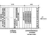
作为增加MPE-FEC纠错功能的结果,在DVB-H中的突发脉冲有这样一种结构,其中发射对应于应用数据表的数据的周期(第一周期)后面跟有发射对应于RS数据表的奇偶校验数据的周期(第二周期)。As a result of the addition of the MPE-FEC error correction function, bursts in DVB-H have a structure in which a period (first period) of transmitting data corresponding to the application data table is followed by transmitting data corresponding to the RS The cycle (second cycle) of the parity data of the table.
考虑到这种突发脉冲结构,本发明的接收装置是这样一种接收装置,它在广播信号的服务周期内进行接收,在非服务周期内切换到省电模式,所述服务周期包括发射应用数据表的第一周期和跟在第一周期后面发射RS数据表的第二周期,包括:接收电路,用于在所述第一周期内进行接收以获取所述应用数据表,并在所述第二周期内进行接收;纠错单元,用于有选择地进行使用整个所述RS数据表的第一纠正和使用所述RS数据表一部分的第二纠正,以纠正在已获取的应用数据表中的位差错;以及切换单元,当作为所述纠错单元进行所述第二纠正的结果纠正所述位差错时,用于在所述第二周期结束之前切换到省电模式。In consideration of this burst structure, the receiving device of the present invention is a receiving device that receives during a service period of a broadcast signal and switches to a power saving mode during a non-service period that includes transmitting applications A first cycle of the data table and a second cycle of transmitting the RS data table following the first cycle, comprising: a receiving circuit for receiving in the first cycle to obtain the application data table, and in the Receive in the second cycle; an error correction unit is used to selectively perform the first correction using the entire RS data table and the second correction using a part of the RS data table, so as to correct the acquired application data table and a switching unit for switching to a power saving mode before the end of the second period when the bit error is corrected as a result of the second correction by the error correction unit.
本发明的效果Effect of the present invention
根据以上的结构,使用整个RS数据表的奇偶校验数据的第一纠正和使用部分RS数据表的奇偶校验数据的第二纠正是有选择地进行的。进行第二纠正时,接收装置可以切换到省电模式而无需等到第二周期结束。这样可以进一步降低电源消耗。According to the above structure, the first correction using the parity data of the entire RS data table and the second correction using the parity data of a part of the RS data table are selectively performed. When the second correction is made, the receiving device can switch to the power saving mode without waiting until the end of the second period. This further reduces power consumption.
在第二周期期间切换到省电模式仅在进行第二纠正时进行。因此,接收装置不会损失接收品质。因此,本发明的接收装置可以在满足品质要求的同时进一步降低电源消耗。Switching to power saving mode during the second period is only done when the second correction is made. Therefore, the reception device does not lose reception quality. Therefore, the receiving device of the present invention can further reduce power consumption while meeting quality requirements.
在这里,应用数据表可以由排列在矩阵中的多个字节组成,其中接收装置进一步包括:检测单元,当所述接收电路获取所述应用数据表时,用于在已获取的所述应用数据表的每一行中,检测有位差错的每个字节的位置,所述第二纠正是擦除纠正,如果所述检测单元在所述行中检测到有位差错的每个字节的位置,则通过使用与每个都有位差错的字节具有相同数目的奇偶校验字节来纠正位差错,以及由所述切换单元切换到省电模式,是在所述第二周期中,将与每个都有位差错的字节具有相同数目的奇偶校验字节添加到所述行时进行的。Here, the application data table may be composed of a plurality of bytes arranged in a matrix, wherein the receiving device further includes: a detection unit, when the receiving circuit obtains the application data table, for In each row of the data table, the position of each byte with a bit error is detected, and the second correction is erasure correction, if the detection unit detects the position of each byte with a bit error in the row position, correcting the bit error by using the same number of parity bytes as each byte having a bit error, and switching to the power saving mode by the switching unit is in the second cycle, This is done when parity bytes are added to the row with the same number of bytes each having a bit error.
根据以上的结构,要接收的奇偶校验字节的数目可以依照应用数据表的每一行中有多少个位差错出现在来增加或减少。一旦接收到数目足以进行擦除纠正的奇偶校验字节,接收装置就可以切换到省电模式。因为用这种方法加速了到省电模式的切换,因此接收装置可以在省电模式中持续较长时间,这样就能够实现更长的电池寿命。According to the above structure, the number of parity bytes to be received can be increased or decreased according to how many bit errors are present in each row of the application data table. Once a sufficient number of parity bytes have been received for erasure correction, the receiving device may switch to a power saving mode. Since switching to the power saving mode is accelerated in this way, the receiving device can last longer in the power saving mode, which enables a longer battery life.
在这里,接收装置可以进一步包括:检测单元,用于检测说明广播信号接收环境的信息,其中如果检测到的所述信息满足预先确定的条件,则在所述第二周期开始之前所述切换单元切换到省电模式,以及如果检测到的所述信息不满足所述预先确定的条件,则所述纠错单元进行所述第一纠正和所述第二纠正中的一个。Here, the receiving device may further include: a detecting unit configured to detect information indicating a broadcast signal receiving environment, wherein if the detected information satisfies a predetermined condition, the switching unit switching to a power saving mode, and if the detected information does not satisfy the predetermined condition, the error correction unit performs one of the first correction and the second correction.
在接收装置进行移动接收的情形中,接收环境随着接收装置的移动速度和周围障碍物的存在这种因素而改变。例如,如果接收装置位于无障碍物的地方或缓慢移动,就能够获得正确的应用数据表而不需要使用RS数据表的任何奇偶校验数据。在这种情形中,RS数据表的奇偶校验数据是不必要的,因此接收装置切换到省电模式而不等待第二周期到达。所以接收电路能在省电模式中停留更长时间。In the case of mobile reception by a receiving device, the receiving environment changes with such factors as the moving speed of the receiving device and the presence of surrounding obstacles. For example, if the receiving device is located in an unobstructed place or moving slowly, the correct application data table can be obtained without using any parity data of the RS data table. In this case, the parity data of the RS data table is unnecessary, so the receiving device switches to the power saving mode without waiting for the arrival of the second cycle. So the receiving circuit can stay in the power saving mode for a longer time.
附图说明Description of drawings
图1示出使用接收装置100的一个系统的结构。FIG. 1 shows the structure of a system using a receiving device 100 .
图2示出广播电台200发射的广播信号和接收装置的状态之间的对应关系。FIG. 2 shows the correspondence between the broadcast signal transmitted by the broadcast station 200 and the state of the receiving device.
图3示出服务突发脉冲的结构。Figure 3 shows the structure of a service burst.
图4示出MPE-FEC帧的结构。Fig. 4 shows the structure of an MPE-FEC frame.
图5说明如何将IP数据中的多个IP数据报存储在应用数据表中。Figure 5 illustrates how multiple IP datagrams in IP data are stored in the application data table.
图6说明产生RS数据表的过程。Figure 6 illustrates the process of generating the RS data table.
图7说明如何发射应用数据表和RS数据表。Figure 7 illustrates how to transmit the application data table and the RS data table.
图8示出与本发明第一实施例相关的接收装置的内部结构。Fig. 8 shows the internal structure of a receiving apparatus related to the first embodiment of the present invention.
图9示出接收装置100的接收操作。FIG. 9 shows the receiving operation of the receiving device 100 .
图10示出要进行擦除纠正的应用数据表。Figure 10 shows an application data table to be erased corrected.
图11示出如何对图10所示应用数据表执行擦除纠正。FIG. 11 shows how erasure correction is performed on the application data table shown in FIG. 10 .
图12示出要进行擦除纠正的一个191字节行的结构。Fig. 12 shows the structure of a 191-byte row to be erased.
图13A示出字节可靠性确定单元14是如何结合对使用CRC-32的MPE段或MPE-FEC段的检错结果,以及对构成使用RS(204,188,16)的段的TS包的纠错结果来确定可靠性的。Fig. 13A shows how the byte
图13B示出如何将可靠性信息表的标志设置为字节可靠性确定单元14确定的结果。FIG. 13B shows how to set the flag of the reliability information table as a result of the determination by the byte
图14A至14C示出了增加一个所有字节都具有可靠性A的MPE-FEC段的实例。14A to 14C show an example of adding an MPE-FEC segment with reliability A for all bytes.
图15A至15C示出了增加一个包括可靠性B字节数据的MPE-FEC段的实例。15A to 15C show an example of adding an MPE-FEC segment including reliability B byte data.
图16说明在认为MPE-FEC帧的每一行至少具有191个可靠性A字节的情形中到省电模式的切换。Figure 16 illustrates switching to power saving mode in the case where each row of an MPE-FEC frame is considered to have at least 191 reliability A bytes.
图17说明在第二周期期间接收第二MPE-FEC段的时候,认识到至少有191个可靠性A字节存在的情形中,到省电模式的切换。Fig. 17 illustrates switching to power save mode in the case where at least 191 reliability A bytes are recognized to be present upon reception of the second MPE-FEC segment during the second period.
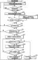
图18是说明FEC控制单元15和电源控制单元30对接收装置进行全面控制的程序的流程图。FIG. 18 is a flowchart illustrating a procedure for overall control of the receiving apparatus by the
图19示出与本发明第二实施例相关的接收装置的内部结构。Fig. 19 shows the internal structure of a receiving apparatus related to the second embodiment of the present invention.
图20是说明第二实施例中解调电路10和电源控制单元30控制程序的流程图。FIG. 20 is a flowchart illustrating the control procedures of the
图21示出与本发明第三实施例相关的接收装置的内部结构。Fig. 21 shows the internal structure of a receiving apparatus related to the third embodiment of the present invention.
图22是说明第三实施例中FEC控制单元15和电源控制单元30的控制程序的流程图。FIG. 22 is a flowchart illustrating control procedures of the
图23是说明本发明第四实施例中FEC控制单元15和电源控制单元30的控制程序的流程图。FIG. 23 is a flowchart illustrating control procedures of the
标号描述Label description
1 …… 天线1 ... antenna
2 …… 调谐器2 ... tuner
3 …… 解调单元3 …… Demodulation unit
4 …… 时间信息提取单元4 …… time information extraction unit
5 …… IP数据再现单元5 ... ... IP data reproduction unit
6 …… 接收环境检测单元6 …… Receiving environment detection unit
10 …… 解调电路10 …… Demodulation circuit
11 …… 帧存储单元11 ... Frame storage unit
12 …… 纠错单元12 …… error correction unit
13 …… 可靠性信息表存储单元13 …… Reliability information table storage unit
14 …… 段可靠性确定单元14 ... segment reliability determination unit
15 …… FEC控制单元15 …… FEC control unit
20 …… MPE-FEC单元20 …… MPE-FEC unit
30 …… 电源控制单元30 …… Power control unit
100 …… 接收装置100 …… Receiver
200 …… 广播电台200 ... radio stations
具体实施方式Detailed ways
<系统中的接收装置><receiving device in the system>
图1示出了使用接收装置100的系统的结构。这一系统为移动终端进行数字广播。接收装置100是在移动终端里接收广播的一种移动装置,并且也具有作为移动电话的功能。正因为如此,接收装置100从广播电台200接收DVB-H广播信号并再现视频和/或音频。FIG. 1 shows the configuration of a system using a receiving device 100 . This system performs digital broadcasting for mobile terminals. The receiving device 100 is a mobile device that receives broadcasts in a mobile terminal, and also functions as a mobile phone. As such, the receiving device 100 receives a DVB-H broadcast signal from the broadcast station 200 and reproduces video and/or audio.
根据DVB-H,同一频道的节目数据以时分复用的方式通过大约每套节目7MHz的合适频带发射。DVB-H采用OFDM(正交频分复用)。OFDM是一种多载波发射技术,它在发射频带内使用多个正交子载波。根据这种技术,发射频带由多个子载波所分割,因此每个码元的持续时间可以更长,这样做具有很强的对抗多径干扰的能力。具有这种特性的OFDM不仅被广泛用于DVB-T和DVB-H中,也被用在日本的陆地数字广播格式ISDB-T(综合服务数字广播—陆地)、无线LAN、第四代移动电话和其它类似的领域中。According to DVB-H, the program data of the same channel are transmitted in a time-division multiplexed manner through a suitable frequency band of approximately 7 MHz per program. DVB-H uses OFDM (Orthogonal Frequency Division Multiplexing). OFDM is a multicarrier transmission technique that uses multiple orthogonal subcarriers within the transmit band. According to this technology, the transmit frequency band is divided by multiple subcarriers, so the duration of each symbol can be longer, which has a strong ability to resist multipath interference. OFDM with this characteristic is widely used not only in DVB-T and DVB-H, but also in Japan's terrestrial digital broadcasting format ISDB-T (Integrated Services Digital Broadcasting-Terrestrial), wireless LAN, fourth-generation mobile phones and other similar fields.
<广播信号和模式切换之间的关系><Relationship between broadcast signal and mode switching>
图2示出了广播电台200发射的广播信号和接收装置100状态之间的对应关系。在第一级上,n个服务的突发脉冲在广播信号中被时分复用。假设接收装置100接收n个服务中服务1的突发脉冲。那么在服务1的突发脉冲中接收装置100处于普通模式中,在服务1的突发脉冲以外的其它周期中处于省电模式,正如在第二级上所示的。FIG. 2 shows the correspondence between the broadcast signal transmitted by the broadcast station 200 and the state of the receiving device 100 . At the first level, bursts of n services are time multiplexed in the broadcast signal. Assume that the receiving apparatus 100 receives a burst of
<突发脉冲结构><burst structure>
图3示出一个服务的突发脉冲结构。在这个图中,第一级示出了服务1的一个突发脉冲,第二级示出了这个突发脉冲的内部结构。服务1的突发脉冲由发射多个MPE段的第一周期和发射64个MPE-FEC段的第二周期组成。将这些MPE段和MPE-FEC段被换成TS包(在第三级),将RS-16(16字节RS码)加到每个TS包中(在第四级),然后对加有RS-16的TS包执行OFDM调制。将结果从广播电台200发射给接收装置100。Figure 3 shows the burst structure of a service. In this figure, the first level shows a burst of
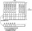
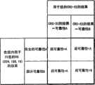
图4示出了MPE-FEC帧的结构。MPE-FEC帧是用于对IP数据报进行编码的编码表。MPE-FEC帧由m行×256列组成。行数m是可变的,可以一直到1024。MPE-FEC帧的前m行×191列称为应用数据表,其中存储了IP数据报。MPE-FEC帧的后m行×64列称为RS数据表或奇偶校验数据表,其中存储了用于IP数据报的m行×64列(奇偶校验字节被装载在段0、1、2、……、最后的FEC段)的奇偶校验数据。在这个规范中,IP数据报和m行×64列的奇偶校验数据的组合称为“IP数据”。Fig. 4 shows the structure of an MPE-FEC frame. MPE-FEC frames are encoding tables used to encode IP datagrams. An MPE-FEC frame consists of m rows x 256 columns. The number of rows m is variable and can be up to 1024. The first m rows × 191 columns of the MPE-FEC frame are called application data tables, in which IP datagrams are stored. The last m rows × 64 columns of the MPE-FEC frame are called RS data tables or parity data tables, which store m rows × 64 columns for IP datagrams (the parity bytes are loaded in
广播电台200在191列的应用数据表和64列的RS数据表的范围内进行RS(255,191,64)编码,以产生64列的奇偶校验数据。在产生m行×64列的奇偶校验数据后,广播电台200能决定是否发射奇偶校验数据。在发射中省略产生的64列奇偶校验数据的一部分这一处理称为“穿孔(puncturing)”。The broadcasting station 200 performs RS (255, 191, 64) encoding within the scope of the 191-column application data table and the 64-column RS data table to generate 64-column parity data. After generating the parity data of m rows×64 columns, the broadcasting station 200 can decide whether to transmit the parity data. The process of omitting a part of the generated 64-column parity data in transmission is called "puncturing".
图5说明包括在IP数据内的多个IP数据报是如何存储在应用数据表中的。如图5A所示,在多个IP数据报的开头构成第一IP数据报(第一IP数据报)的字节数据,从顶部到底部存储在应用数据表的最左边一列。一旦存满了最左边的列,第一IP数据报的其余字节数据(第一IP数据报内容),从顶部到底部存储在左边第二列。在完成对第一IP数据报的存储之后,构成下一个IP数据报(第二IP数据报)的字节数据,从顶部到底部存储在左边第二列的剩余部分,如图5B所示。一旦左边第二列存满,下一个IP数据报中的其余字节数据(第二IP数据报继续),从顶部到底部存储在应用数据表的左边第三列。这个操作重复进行直到IP数据的最后IP数据报(最后的IP数据报)存储完毕(图5C)。Figure 5 illustrates how multiple IP datagrams included in IP data are stored in the application data table. As shown in FIG. 5A, the byte data constituting the first IP datagram (first IP datagram) at the beginning of a plurality of IP datagrams is stored in the leftmost column of the application data table from top to bottom. Once the leftmost column is filled, the remaining byte data of the first IP datagram (content of the first IP datagram), from top to bottom, is stored in the second left column. After the storage of the first IP datagram is completed, the byte data constituting the next IP datagram (the second IP datagram) is stored in the remainder of the second column on the left from top to bottom, as shown in FIG. 5B . Once the second left column is full, the remaining bytes of data in the next IP datagram (continuing with the second IP datagram), are stored in the third left column of the application data table from top to bottom. This operation is repeated until the last IP datagram (last IP datagram) of the IP data is stored (FIG. 5C).
这样,包括在IP数据中的IP数据报被存储在m行×191列的应用数据表中,从最左边的列的顶部开始存储,它们之间没有任何间隙。当IP数据报无任何间隙地存储在应用数据表中时,在应用数据表的末端存在一个空白区域。将一个静止的值(通常为“00H”)作为填充字节插入这个空白区域,如图5D所示。Thus, the IP datagrams included in the IP data are stored in the application data table of m rows x 191 columns starting from the top of the leftmost column without any gaps between them. When an IP datagram is stored in the application data table without any gap, there is a blank area at the end of the application data table. A static value (usually "00H") is inserted into this blank space as a stuffing byte, as shown in FIG. 5D.
图6说明产生RS数据表的过程。Figure 6 illustrates the process of generating the RS data table.
在填充整个应用数据表之后,在应用数据表的每一行(由191个字节组成)进行RS(255,191,64)编码以获得对应于这一行的64字节奇偶校验数据,如图6A所示。作为对应用数据表的每一行进行RS(255,191,64)编码的结果,获得m组64字节的奇偶校验数据(图6B)。假设64字节的奇偶校验数据构成RS数据表的一行。于是获得了m行×64列的RS数据表(图6C)。After filling the entire application data table, perform RS (255, 191, 64) encoding on each row of the application data table (composed of 191 bytes) to obtain the 64-byte parity data corresponding to this row, as shown in the figure 6A. As a result of performing RS (255, 191, 64) encoding on each row of the application data table, m sets of 64-byte parity data are obtained (FIG. 6B). Assume that 64 bytes of parity data constitute one row of the RS data table. Then the RS data table with m rows×64 columns is obtained ( FIG. 6C ).
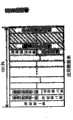
图7说明应用数据表和RS数据表是如何发射的。第一级示出了应用数据表和RS数据表。如第二级所示,应用数据表中的每个IP数据报都通过添加报头给IP数据报的开头和添加CRC-32(32字节循环冗余码)给IP数据报的末尾来进行封装。结果,产生了MPE段。同样,RS数据表的每一列都通过添加报头给这一列的开头和添加CRC-32(32字节循环冗余码)给这一列的末尾来进行封装。结果,产生MPE-FEC段。每一段的报头都包括了时间信息ΔT,它表明从段的接收开始到下一个突发脉冲开始之间的时间。同样,每个MPE-FEC段的报头也包括信息表明产生应用数据表时所用填充字节的列数。Figure 7 illustrates how the application data table and RS data table are transmitted. The first level shows the application data table and the RS data table. As shown in the second level, each IP datagram in the application data table is encapsulated by adding a header to the beginning of the IP datagram and adding a CRC-32 (32-byte cyclic redundancy code) to the end of the IP datagram . As a result, MPE segments are generated. Likewise, each column of the RS data table is encapsulated by adding a header to the beginning of the column and a CRC-32 (32-byte cyclic redundancy code) to the end of the column. As a result, MPE-FEC segments are generated. The header of each segment includes time information ΔT, which indicates the time between the reception of the segment and the start of the next burst. Likewise, the header of each MPE-FEC section also includes information indicating the column number of padding bytes used when generating the application data table.
在这里,不发射应用数据表中填充字节中的穿孔数据串和RS数据表中的奇偶校验数据。Here, the punctured data string in the stuffing bytes in the application data table and the parity data in the RS data table are not transmitted.
将利用以上方法产生的MPE段和MPE-FEC段转换为如第三级所示的TS包。将TS报头添加给TS包,对TS包进行RS(204,188,16)编码,然后将DVB-H调制应用于TS包,如第四级所示。将结果从广播电台200发射给接收装置100。在这里,将对应于一个MPE-FEC帧的数据作为一个突发脉冲发射。在以下说明中,假设要发射的MPE-FEC帧没有填充字节,也没有穿孔数据。Convert the MPE section and MPE-FEC section generated by the above method into TS packets as shown in the third level. A TS header is added to the TS packet, the TS packet is RS(204, 188, 16) encoded, and then DVB-H modulation is applied to the TS packet, as shown in the fourth stage. The result is transmitted from the broadcasting station 200 to the receiving device 100 . Here, data corresponding to one MPE-FEC frame is transmitted as one burst. In the following description, it is assumed that the MPE-FEC frame to be transmitted has no padding bytes and no punctured data.
这样,根据DVB-H,突发脉冲的第一部分携带数据,突发脉冲的后一部分携带奇偶校验数据。在本发明的第一实施例中,将DVB-H的这一特性用于降低电源消耗。Thus, according to DVB-H, the first part of the burst carries the data and the second part of the burst carries the parity data. In a first embodiment of the invention, this feature of DVB-H is used to reduce power consumption.
图8说明与第一实施例相关的接收装置的内部构造。在附图中,这个接收装置包括三个组成部件,它们是解调电路10、MPE-FEC单元20和电源控制单元30。Fig. 8 illustrates the internal configuration of the receiving apparatus related to the first embodiment. In the drawing, this receiving device includes three components, which are a
<解调电路10的内部构造><Internal Structure of
首先说明解调电路10的内部构造。解调电路10是一个集成电路,包括天线1、调谐器2、解调单元3、时间信息提取单元4和IP数据再现单元5。在从接收装置的内部电池接受电力时,解调电路10接收DVB-H广播信号并输出MPE段和MPE-FEC段。当突发脉冲开始时解调电路10的电源供应开始,并且当电源控制单元30确定停止电源供应时电源供应结束。在本实施例中,将电源供应给电源控制单元30而不供应给解调电路10的状态称为“省电模式”。First, the internal structure of the
天线1接收DVB-H广播信号,并把接收到的信号输出给调谐器2。
调谐器2为天线1的接收选择所需要的信道,并把所选信道的信号转换为中频信号。The
解调单元3使用A/D转换器将从调谐器2输出的中频信号转换为数字信号,然后通过正交解调将这个数字信号转换为OFDM基带信号。这个OFDM基带信号是一个时域信号。解调单元3通过FFT(快速傅立叶变换)将这个属于时域信号的基带信号进一步转换为频域信号。在转换期间,再现时钟和其它的同步信息。转换为频域信号的基带信号经过发射线路均衡。在这之后,解调单元3对频域信号进行纠错,例如Viterbi解码和RS(204,188,16)解码。解调单元3输出用这种方法获取的TS包给时间信息提取单元4。时间信息提取单元3传递这个TS包给IP数据再现单元5。解调单元3也通知字节可靠性确定单元14作为RS解码结果的TS包中的字节差错是否被完全纠正。The
时间信息提取单元4提取时间信息ΔT,它表明从MPE段或MPE-FEC段的报头到下一个突发脉冲开头的时间。时间信息提取单元4输出提取的时间信息ΔT给电源控制单元30。The time
IP数据再现单元5去除从时间信息提取单元4传递来的多个TS包的封装。去除封装是从组成MPE段的TS包再现IP数据报以及从组成MPE-FEC段的TS包再现奇偶校验数据列所进行的操作。IP数据再现单元5将再现的IP数据报输入MPE-FEC单元20。在去除封装的时候,IP数据再现单元5利用CRC-32对每一段进行检错,并通知字节可靠性确定单元14这个段中是否有差错存在。The IP
<MPE-FEC单元20的内部构造><Internal structure of MPE-
到此为止结束了对解调电路10内部构造的说明。下面说明MPE-FEC单元20的内部构造。This concludes the description of the internal structure of the
MPE-FEC单元20是一个集成电路,包括帧存储单元11、纠错单元12、可靠性信息表存储单元13、字节可靠性确定单元14和FEC控制单元15。在从接收装置的内部电池接受电力时,MPE-FEC单元20进行纠错并输出IP数据报。当突发脉冲开始时对MPE-FEC单元20的电源供应开始,并且当纠错单元12完成纠错时结束。The MPE-
帧存储单元11存储从IP数据再现单元5输出的MPE段和MPE-FEC段,以重建MPE-FEC帧。
纠错单元12对帧存储单元11中以行为单元的MPE-FEC帧进行RS(255,191,64)解码。还有,纠错单元12在预定条件下进行擦除纠正。在这里所提到的擦除纠正是这样一项操作,它是在接收应用数据表时,在有位差错的各个字节的位置是可检测到的情形中,通过使用与具有位差错的字节一样数目的奇偶校验字节来纠正具有位差错的字节。The
将64列奇偶校验数据以水平方向添加到应用数据表的行中。在每一行中,如果在64列奇偶校验数据中与具有位差错的字节一样数量的奇偶校验字节里没有位差错存在,那么具有位差错的字节是可纠正的。Adds 64 columns of parity data horizontally to the rows of the application data table. In each row, a byte with a bit error is correctable if no bit error exists in as many parity bytes as there are bytes with a bit error in the parity data of 64 columns.
也就是说,如果识别出结合了MPE-FEC帧每一行的字节数据和奇偶校验数据的255字节中的191(=255-64)字节没有位差错,那么具有位差错的字节可以通过擦除纠正来纠正。That is, if it is recognized that 191 (=255-64) bytes of 255 bytes combining byte data and parity data of each row of the MPE-FEC frame have no bit error, then the byte with bit error Can be corrected by erasing correction.
可靠性信息表存储单元13是用于存储可靠性信息表的存储器。可靠性信息表由m行×255列的标志组成。每一个标志对应于MPE-FEC帧的m行×255列中一个不同的字节或奇偶校验字节。当这个标志为“开”时,这表明对应的字节或奇偶校验字节也许有位差错。当这个标志为“关”时,这表明对应的字节或奇偶校验字节没有位差错。详细的说,在可靠性信息表中的每一个标志通过表明对应的字节或奇偶校验字节是否可能有位差错,来说明对应的字节或奇偶校验字节是有可靠性A(无位差错)还是有可靠性B(有位差错)。令x是从1到m的任意数字,y是从1到255的任意数字。于是,在可靠性信息表中的第x行和第y列的标志表明,在MPE-FEC帧中的第x行和第y列的字节或奇偶校验字节是否具有位差错。The reliability information
基于面向包的可靠性和面向段的可靠性,字节可靠性确定单元14确定MPE-FEC帧每个字节的可靠性,所述包可靠性是作为在每个TS包上使用RS(204,188,16)进行纠错的结果获得的,并且是从所述解调器单元3得到的通知,所述段可靠性是作为在每个段上使用CRC-32进行检错的结果而获得的,并且是从IP数据再现单元5得到的通知。字节可靠性确定单元14根据这一确定结果在可靠性信息表存储单元13中产生可靠性信息表。Based on packet-oriented reliability and segment-oriented reliability, the byte
FEC控制单元15确定在应用数据表的每一行中是否至少有191个字节没有位差错。如果在应用数据表的191列中发现有位差错,FEC控制单元15执行RS(255,191,64)或擦除纠正。如果在应用数据表的191列中没有发现位差错,FEC控制单元15就确定没有必要进行纠错。如果在MPE-FEC帧的每一行中无位差错的字节的数目比191要少,FEC控制单元15就确定纠错是不可能的。换句话说,参照不仅和应用数据表有关,还和RS数据表有关的可靠性信息表,如果在每一行内,在255列中至少有191列没有位差错,则纠错是可能的。即使应用数据表的每一行中有190个字节无位差错时,如果RS数据表每一行中的所有64个字节都有位差错,则纠错是不可能的。The
<电源控制单元30><
基于字节可靠性确定单元14的确定结果和时间信息ΔT,电源控制单元30控制对解调电路10和MPE-FEC单元20的电源供应。电源控制单元30从时间信息ΔT计算下一个突发脉冲的时间,并且考虑到同步时间之类,计算下一个突发脉冲的接收开始时间。电源控制单元30基于这个接收开始时间给解调电路10和MPE-FEC电路20提供电源供应。当字节可靠性确定单元14确定在MPE-FEC帧的每一行中至少有191个字节具有可靠性A时,电源控制单元30决定停止对解调电路10的电源供应。Based on the determination result of the byte
<接收操作><receive action>
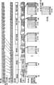
图9示出了通过接收装置100执行的接收操作。第一级说明通过解调单元3进行维特比解码后的TS包(每一个都是204个字节长)。第二级说明使用RS(204,188,16)进行纠错的结果。作为通过解调单元3使用RS(204,188,16)进行的这一纠错的结果,获得TS包(每一个都是188个字节长)。FIG. 9 shows receiving operations performed by the receiving device 100 . The first level shows Viterbi-decoded TS packets (each 204 bytes long) by
第三级说明将TS包转换成以段为单位以后的MPE段和MPE-FEC段。第四级说明MPE段和MPE-FEC段的内部结构。每一个MPE段和MPE-FEC段都包含报头和CRC-32。IP数据再现单元5从每一段中移除报头,并且使用CRC-32执行检错。作为IP数据再现单元5在顺序输入其中的每一个MPE段和MPE-FEC段上执行这个操作的结果,在存储器上一次获得应用数据表的所有IP数据报和RS数据表的一列,如第五级所示。在这里,将值“00H”赋给每一个填充字节,并且将一个适当的值赋给穿孔字节。The third level describes the conversion of TS packets into MPE segments and MPE-FEC segments in units of segments. The fourth level describes the internal structure of the MPE section and the MPE-FEC section. Each MPE section and MPE-FEC section contains a header and a CRC-32. The IP
在获取MPE-FEC帧的应用数据表和RS数据表后,基于MPE-FEC帧的RS数据表,使用RS(255,191,64)的进行纠错,作为如第六级所示的获得m行×191列的字节数据的结果。After obtaining the application data table and RS data table of the MPE-FEC frame, based on the RS data table of the MPE-FEC frame, use RS (255, 191, 64) to perform error correction, as the obtained m as shown in the sixth level The result of byte data in rows × 191 columns.
下面说明字节可靠性确定单元14用什么样的判据来确定每个字节的可靠性。What criterion the byte
<擦除纠正的细节><details corrected by erasure>
下面参考图10至12说明用于RS解码的擦除纠正如何执行。How erasure correction for RS decoding is performed is explained below with reference to FIGS. 10 to 12 .
图10示出了要进行擦除纠正的应用数据表。Figure 10 shows an application data table to be erased corrected.
在附图中,阴影区表明第二、第四和第六列的MPE段中的位差错不能由解调单元3通过面向包的纠错和IP数据再现单元5通过使用CRC-32的面向段的检错来纠正,因此位差错仍旧存在于第二、第四和第六列的MPE段中(这里应该指出,MPE段没有以列为单位布局)。In the figure, the shaded area indicates that bit errors in the MPE segments of the second, fourth and sixth columns cannot be corrected by the
图11说明如何在图10所示的应用数据表上执行擦除纠正。在附图中,水平箭头表明擦除纠正是在应用数据表的每一行(191个字节数据)上进行的。Figure 11 illustrates how erasure correction is performed on the application data table shown in Figure 10. In the attached figure, horizontal arrows indicate that erasure correction is performed on each row (191 bytes of data) of the application data table.
图12说明要进行擦除纠正的191字节行的结构。假设附图中画上了圈的行(191个字节的数据)要进行擦除纠正。因为应用数据表的第二、第四和第六列有位差错,如图10所示,可以认为组成这一行的191个字节的第二、第四和第六个字节有位差错。因此,如果在水平方向上将与有位差错的那些相同数目的字节添加给应用数据表,则这一行中的位差错可以通过擦除纠正来纠正。通过对应用数据表的所有行重复这种擦除纠正,可以纠正应用数据表中的位差错而不使用整个RS数据表。Fig. 12 illustrates the structure of a 191-byte row to be erasure corrected. Assume that the circled rows (191 bytes of data) in the drawing are subject to erasure correction. Because there are bit errors in the second, fourth, and sixth columns of the application data table, as shown in FIG. 10, it can be considered that the second, fourth, and sixth bytes of the 191 bytes that make up this row have bit errors. Therefore, if the same number of bytes as those with bit errors are added to the application data table in the horizontal direction, the bit errors in this row can be corrected by erasure correction. By repeating this erasure correction for all rows of the application data table, bit errors in the application data table can be corrected without using the entire RS data table.
<纠错结果和可靠性确定之间的关系><Relationship between Error Correction Result and Reliability Determination>
如上所述,擦除纠正基于这样一个前提,也就是能够正确地确定在每一个MPE段和MPE-FEC段中是否存在位差错。下面详细说明如何确定位差错是否存在,也就是说,如何确定每个字节的可靠性。As described above, erasure correction is based on the premise that whether or not a bit error exists in each MPE segment and MPE-FEC segment can be correctly determined. The following explains in detail how to determine whether a bit error exists, that is, how to determine the reliability of each byte.
图13A说明根据在字节所属段上使用CRC-32进行检错的结果,以及在字节所属TS包上使用RS(204,188,16)进行纠错的结果这两者的结合,字节可靠性确定单元14做什么种类的确定。Figure 13A illustrates the combination of the result of using CRC-32 for error detection on the segment to which the byte belongs and the result of error correction using RS(204, 188, 16) on the TS packet to which the byte belongs. The
如果使用字节所属段的CRC-32进行检错的结果是可靠性A,并且使用字节所属TS包的RS(204,188,16)进行纠错的结果是可靠性A,就确定这个字节具有可靠性A。If the result of error detection using the CRC-32 of the segment to which the byte belongs is reliability A, and the result of error correction using the RS (204, 188, 16) of the TS packet to which the byte belongs is reliability A, then determine this word Section has reliability A.
如果使用字节所属段的CRC-32进行检错的结果是可靠性B,但是使用字节所属TS包的RS(204,188,16)进行纠错的结果是可靠性A,就确定这个字节具有可靠性A。If the result of error detection using the CRC-32 of the segment to which the byte belongs is reliability B, but the result of error correction using the RS (204, 188, 16) of the TS packet to which the byte belongs is reliability A, then determine this word Section has reliability A.
如果使用字节所属段的CRC-32进行检错的结果是可靠性A,但是使用字节所属TS包的RS(204,188,16)进行纠错的结果是可靠性B,就确定这个字节具有可靠性A。If the result of error detection using the CRC-32 of the segment to which the byte belongs is reliability A, but the result of error correction using the RS (204, 188, 16) of the TS packet to which the byte belongs is reliability B, then determine this word Section has reliability A.
另一方面,如果使用字节所属段的CRC-32进行检错的结果是可靠性B,并且使用字节所属TS包的RS(204,188,16)进行纠错的结果是可靠性B,就确定这个字节具有可靠性B。On the other hand, if the result of error detection using the CRC-32 of the segment to which the byte belongs is reliability B, and the result of error correction using the RS (204, 188, 16) of the TS packet to which the byte belongs is reliability B, It is determined that this byte has reliability B.
这样,如果在使用这个段的CRC-32进行检错的结果和使用这个TS包的RS(204,188,16)进行纠错的结果中没有检测到差错,就确定这个字节具有可靠性A。In this way, if no error is detected in the result of error detection using CRC-32 of this segment and the result of error correction using RS (204, 188, 16) of this TS packet, it is determined that this byte has reliability A .
<根据可靠性确定进行标志设置><Flag setting based on reliability determination>
图13B说明如何根据字节可靠性确定单元14的确定结果设置可靠性信息表的标志。作为图13A所示确定的结果,确定字节具有可靠性A时,将可靠性信息表中对应于这个字节的标志设置为可靠性A。在图13B中的标记o表明对应的字节具有可靠性A。FIG. 13B illustrates how to set the flag of the reliability information table according to the determination result of the byte
<更新可靠性信息表的过程><Process of Updating Reliability Information Table>
下面说明作为对MPE-FEC段接收的结果,更新可靠性信息表的过程。The procedure for updating the reliability information table as a result of reception of the MPE-FEC section will be described below.
在图14A至14C中,在左边给出的说明表明在应用数据表的第一至第四行的每一行中有多少个。标志(也就是多少个可靠性A的字节)。图14A涉及再现应用数据表所有IP数据报的一个阶段。从附图中可以看到,第一行有191个可靠性A字节,第二行有190个可靠性A字节,第三行和第四行每个都有189个可靠性A字节。In FIGS. 14A to 14C, the description given on the left shows how many are in each of the first to fourth rows of the application data table. Flag (that is, how many bytes of reliability A). Figure 14A relates to a phase of rendering all IP datagrams of the application data table. As you can see from the attached image, the first row has 191 Reliability A bytes, the second row has 190 Reliability A bytes, and the third and fourth rows each have 189 Reliability A bytes .
图14B说明作为增加第一MPE-FEC段的结果,可靠性信息表是如何更新的。当组成增加给MPE-FEC帧的奇偶校验数据的MPE-FEC段具有可靠性A时,第一行至第四行中可靠性A字节的数目加1,分别变为192、191、190和190,如同左边的注释所表明的一样。Fig. 14B illustrates how the reliability information table is updated as a result of adding the first MPE-FEC section. When the MPE-FEC segment that makes up the parity data added to the MPE-FEC frame has reliability A, the number of reliability A bytes in the first to fourth rows is increased by 1, and becomes 192, 191, and 190 respectively and 190, as the note on the left indicates.
图14C说明作为增加第二MPE-FEC段的结果,可靠性信息表是如何更新的。当组成增加给MPE-FEC帧的奇偶校验数据的MPE-FEC段具有可靠性A时,第一行至第四行中可靠性A字节的数目加1,分别变为193、192、191和191,如同左边的注释所表明的一样。Fig. 14C illustrates how the reliability information table is updated as a result of adding the second MPE-FEC segment. When the MPE-FEC segment that makes up the parity data added to the MPE-FEC frame has reliability A, the number of reliability A bytes in the first to fourth rows is increased by 1, and becomes 193, 192, and 191 respectively and 191, as the note on the left indicates.
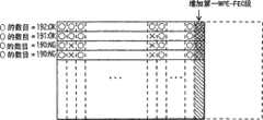
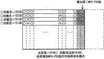
图14A至14C示出了增加一个所有字节都具有可靠性A的MPE-FEC段的实例。图15A至15C示出了增加一个包括可靠性B字节数据的MPE-FEC段的实例。14A to 14C show an example of adding an MPE-FEC segment with reliability A for all bytes. 15A to 15C show an example of adding an MPE-FEC segment including reliability B byte data.
图15A与图14B相同。也就是说,在第一行至第四行中可靠性A字节的数目分别为192、191、190和190。Fig. 15A is the same as Fig. 14B. That is, the numbers of reliability A bytes in the first to fourth rows are 192, 191, 190, and 190, respectively.
图15B说明作为增加第二MPE-FEC段的结果,可靠性信息表是如何更新的。当增加到应用数据表中的MPE-FEC段包含第三行中的可靠性B字节时,第一行到第四行中可靠性A字节的数目分别为193、192、190和191,如左边的注释所示。Fig. 15B illustrates how the reliability information table is updated as a result of adding the second MPE-FEC section. When the MPE-FEC section added to the application data table contains reliability B bytes in the third row, the numbers of reliability A bytes in the first to fourth rows are 193, 192, 190, and 191, respectively, As indicated in the note to the left.
图15C说明作为增加第三MPE-FEC段的结果,可靠性信息表是如何更新的。当增加给应用数据表的MPE-FEC段由全部具有可靠性A的字节组成时,第一行到第四行中可靠性A字节的数目加1,分别为194、193、191和192,如左边的注释所示。Fig. 15C illustrates how the reliability information table is updated as a result of adding the third MPE-FEC section. When the MPE-FEC section added to the application data table consists of all bytes with reliability A, the number of reliability A bytes in the first row to the fourth row is increased by 1, which are 194, 193, 191 and 192 respectively , as shown in the note on the left.
在图14和图15所示的以上过程中,如果在MPE-FEC帧的每一行中可靠性A字节的数目至少为191,则在MPE-FEC帧中的位差错可以通过执行擦除纠正来纠正。这样就不必等待在第二周期内接收全部的64个MPE-FEC段。因此可加速切换到省电模式。In the above process shown in Figure 14 and Figure 15, if the number of reliability A bytes in each row of the MPE-FEC frame is at least 191, the bit errors in the MPE-FEC frame can be corrected by performing erasure to correct. This eliminates the need to wait for all 64 MPE-FEC segments to be received within the second period. Switching to power saving mode can thus be accelerated.
图16说明在认为MPE-FEC帧的每一行至少具有191个可靠性A字节的情形中到省电模式的切换。Figure 16 illustrates switching to power saving mode in the case where each row of an MPE-FEC frame is considered to have at least 191 reliability A bytes.
如果是在第二周期开始之前认识到至少有191个可靠性A字节存在的,则电源控制单元30能够在第二周期开始之前切换到省电模式。If it is recognized that at least 191 reliability A bytes are present before the start of the second cycle, the
图17说明在第二周期期间接收第二MPE-FEC段的时候,认识到至少有191个可靠性A字节存在的情形中,到省电模式的切换。如果是在第二周期期间认识到的,电源控制单元30甚至能够在第二周期中切换到省电模式。Fig. 17 illustrates switching to power save mode in the case where at least 191 reliability A bytes are recognized to be present upon reception of the second MPE-FEC segment during the second period. If recognized during the second period, the
<通过软件实现FEC控制单元15和电源控制单元30><Realization of
下面说明通过软件实现FEC控制单元15和电源控制单元30。通过产生一个程序用于图18的流程图所示的控制程序,并且在接收装置中有一个CPU来执行这个程序,FEC控制单元15和电源控制单元30可以在接收装置中实现。Realization of the
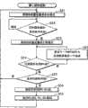
图18是说明FEC控制单元15和电源控制单元30对接收装置整体控制过程的流程图。在这个流程图中,重复以下过程。将接收装置设置为省电模式后(步骤S21),检测目标服务的突发脉冲是否开始(步骤S22)。如果目标服务的突发脉冲开始了(步骤S22:是),就将接收装置设置成正常模式(步骤S23),并且在返回步骤S21之前执行步骤S24至S23。FIG. 18 is a flowchart illustrating the overall control process of the receiving device by the
步骤S24至S32包括由步骤S24和S25组成的第一循环和由步骤S28至S30组成的第二循环。Steps S24 to S32 include a first loop consisting of steps S24 and S25 and a second loop consisting of steps S28 to S30.
第一循环重复获得一个MPE段,并将其设置成应用数据表的一部分或整个列(步骤S25)的处理,直到获得所有MPE段(步骤S24:是)。The first loop repeats the process of obtaining one MPE segment and setting it as a part or the entire column of the application data table (step S25) until all MPE segments are obtained (step S24: Yes).
步骤S26确定用这种方法获得的应用数据表的每一行中所有字节是否都具有可靠性A。如果所有字节都具有可靠性A,那么这一过程回到步骤S21,切换到省电模式。Step S26 determines whether or not all bytes in each row of the application data table obtained in this way have reliability A. If all bytes have reliability A, then the process goes back to step S21 to switch to power saving mode.
如果任何一行包括有不具有可靠性A的字节,则构造应用数据表(步骤S27),然后执行由步骤S28至S30组成的第二循环。If any row includes bytes that do not have reliability A, the application data table is constructed (step S27), and then the second loop consisting of steps S28 to S30 is executed.
第二循环重复获得一个MPE-FEC段,并将其设置成RS数据表的一列(步骤S29)的处理,直到步骤S28和S30的任何一个结果为是。The second loop repeats the process of obtaining an MPE-FEC segment and setting it as a column of the RS data table (step S29) until either the result of steps S28 or S30 is YES.
步骤S28确定在MPE-FEC帧的每一行中是否至少有191个字节具有可靠性A。如果至少191个字节具有可靠性A,则执行擦除纠正(步骤S31),然后过程回到步骤S21,切换到省电模式。Step S28 determines whether at least 191 bytes have reliability A in each row of the MPE-FEC frame. If at least 191 bytes have reliability A, erasure correction is performed (step S31), and then the process returns to step S21 to switch to the power saving mode.
步骤S30确定是否获得了RS数据表的所有MPE-FEC段。如果已经获得了所有的MPE-FEC段,则执行使用RS(255,191,64)的纠错(步骤S32),然后过程回到步骤S21,切换到省电模式。Step S30 determines whether all MPE-FEC sections of the RS data table are obtained. If all MPE-FEC sections have been obtained, error correction using RS (255, 191, 64) is performed (step S32), and then the process returns to step S21, switching to power saving mode.
如果步骤S28的结果为是,就将接收装置切换到省电模式,而不等候收到所有的MPE-FEC段。因此接收装置可以在更长的时间内处在省电模式中。If the result of step S28 is yes, the receiving device is switched to power saving mode without waiting for all MPE-FEC segments to be received. Therefore, the receiving device can be in the power saving mode for a longer period of time.
这样,根据本实施例,可以根据在应用数据表的每一行中会发生多少个位差错来调整要接收的奇偶校验字节的数目。也就是说,一旦收到数量足够进行擦除纠正的奇偶校验字节,就可以将接收装置切换到省电模式。因为使用这种方法能加速切换到省电模式,因此接收装置可以在更长时间内处在省电模式中,这样就能促成电池寿命更长。Thus, according to this embodiment, the number of parity bytes to be received can be adjusted according to how many bit errors will occur in each row of the application data table. That is, once a sufficient number of parity bytes has been received for erasure correction, the receiving device can be switched to a power saving mode. Because switching to power-saving mode is accelerated using this method, the receiving device can stay in power-saving mode for a longer period of time, which results in longer battery life.
降低电源消耗的这一效果取决于在一个突发脉冲中应用数据表和RS数据表的构成比率。假设应用数据表有191列,而RS数据表由没有穿孔数据表的64列的奇偶校验数据表组成。在这种情形中,如果接收环境良好,那么电源周期最多可以缩短大约25%(=64/255)。This effect of reducing power consumption depends on the composition ratio of the application data table and the RS data table in one burst. Assume that the application data table has 191 columns, and the RS data table consists of a 64-column parity data table without a punched data table. In this case, if the reception environment is good, the power cycle can be shortened by at most about 25% (=64/255).
同样,根据本实施例,如果使用部分RS数据表就能够纠正位差错,那么即使在第二周期中,接收装置也能切换到省电模式。这也就是说,在不能通过与DVB-T所具有的同样的纠错功能进行纠正位差错,但是没有必要使用整个RS数据表纠错的情形中,接收装置可以通过执行擦除纠正切换到省电模式,而无须等待第二周期结束。因为接收装置可以切换到省电模式而无须等待第二周期结束,因此接收装置可以在更长时间内处在省电模式中。Also, according to the present embodiment, if a bit error can be corrected using a part of the RS data table, the receiving apparatus can switch to the power saving mode even in the second cycle. That is to say, in the case where bit errors cannot be corrected by the same error correction function as DVB-T has, but it is not necessary to use the entire RS data table for error correction, the receiving device can switch to save by performing erasure correction. power mode without waiting for the end of the second cycle. Since the receiving device can switch to the power saving mode without waiting for the end of the second period, the receiving device can stay in the power saving mode for a longer period of time.
这里应该指出,依赖于解调电路10的电源供应什么时候停止,存在已经收到确定要停止电源供应的列之后的一列或多列的可能性。即使在这种情形中接收到一个额外的列,接收装置仍然可以切换到省电模式而无须等待收到整个RS数据表。因此依然可以达到降低电源消耗的效果。It should be noted here that depending on when the power supply to the
(第二实施例)(second embodiment)
图19示出了一个与本发明的第二实施例相关的接收装置的内部构造。第二实施例的接收装置与图8中示出的不同,差别在于提供了解调电路10中的接收环境检测单元6来代替可靠性信息表存储单元13和字节可靠性确定单元14。FIG. 19 shows an internal construction of a receiving apparatus related to a second embodiment of the present invention. The receiving apparatus of the second embodiment differs from that shown in FIG. 8 in that a reception
接收环境检测单元6检测接收环境,并输出一个值(评估值)用于评估检测到的接收环境。将输出的接收环境评估值输入FEC控制单元15。在本实施例中,将AGC电平、C/N值、接收信号差错率和接收装置移动速度用作这种接收环境评估值。The reception
<接收环境评估值><Receiving environmental assessment value>
将以上每个接收环境评估值说明如下。Each of the above reception environment evaluation values is explained as follows.
AGC电平是解调单元3中自动增益控制(AGC)的信号电平。当这个AGC的信号电平低于指定值时,FEC控制单元15就认为接收环境不好。The AGC level is the signal level of automatic gain control (AGC) in the
接收信号的C/N值是接收信号的信号功率与噪声功率之比,并且是从接收信号中包含的导频信号估计出来的发射路径中计算出来的。当C/N值低于指定值时,FEC控制单元15就认为接收环境不好。The C/N value of the received signal is the ratio of the signal power of the received signal to the noise power, and is calculated from the transmission path estimated from the pilot signal contained in the received signal. When the C/N value is lower than a specified value, the
从包含在接收信号中的导频信号中所估计的发射路径的时间变化来计算接收装置移动速度。当接收装置移动速度大于指定值时,FEC控制单元15就认为接收环境不好。The receiving device moving speed is calculated from the time variation of the transmission path estimated from the pilot signal included in the received signal. When the moving speed of the receiving device is greater than a specified value, the
按照TS包在RS解码前后的差错数量来检测差错率。当差错率较高时,FEC控制单元15就认为接收环境更差。The error rate is detected according to the number of errors of TS packets before and after RS decoding. When the error rate is high, the
在终端也使用例如无线LAN、移动电话、蓝牙或红外通信这种通信功能的情形中,广播信号的接收环境由于无线通信干扰之类可能不好。因此,突发脉冲的接收期间通过通信功能检测到发射或接收时,认为接收环境不好。在这里,基于来自终端的外部CPU的通知信息,检测终端是否正在进行通信是可能的。In a case where a terminal also uses a communication function such as wireless LAN, mobile phone, Bluetooth, or infrared communication, the reception environment of broadcast signals may be bad due to wireless communication interference or the like. Therefore, when transmission or reception is detected by the communication function during burst reception, it is considered that the reception environment is not good. Here, based on the notification information from the external CPU of the terminal, it is possible to detect whether the terminal is communicating.
(FEC控制单元15,电源控制单元30)(
到此为止完成了对接收环境评估值的说明。下面介绍第二实施例中FEC控制单元15和电源控制单元30的控制程序。This completes the description of receiving the environmental evaluation value. The control procedures of the
图20是一个流程图,它说明第二实施例中FEC控制单元15和电源控制单元30的控制程序。在这个流程图中,提供步骤S35至S36来代替图18中的步骤S26至S30和S32。步骤S35使用接收环境评估值判断接收环境是否好。如果接收环境好,过程回到步骤S21。如果接收环境不好,在接收所有MPE-FEC段之后(步骤S36),用RS(255,191,64)进行纠错(步骤S32)。Fig. 20 is a flowchart illustrating the control procedures of the
这样,根据本实施例,例如当接收装置保持几乎静止的时候,根本就不接收RS数据表,这样就能降低大约25%的电源消耗。例如,一旦接收装置开始移动,执行与DVB-H相同的纠错以保证接收品质。这样就可以实现高移动性的接收装置。Thus, according to the present embodiment, for example, when the receiving apparatus remains almost stationary, the RS data table is not received at all, so that power consumption can be reduced by about 25%. For example, once the receiving device starts to move, the same error correction as DVB-H is performed to ensure reception quality. In this way, a receiving device with high mobility can be realized.
同样,根据本实施例,如果接收环境良好或者接收内容没有位差错,就保持停止给部分MPE-FEC单元20供电。这样就能进一步降低电源消耗。Also, according to the present embodiment, if the receiving environment is good or the received content has no bit errors, the power supply to part of the MPE-
(第三实施例)(third embodiment)
本发明的第三实施例涉及在一个接收装置中结合第一实施例的字节可靠性确定单元14和FEC控制单元15以及第二实施例的接收环境检测单元6的改进。The third embodiment of the present invention relates to an improvement combining the byte
图21示出了本发明的第三实施例涉及的接收装置的内部构造。第三实施例的接收装置与图8中所示出的不同,差别在于,字节可靠性确定单元14、可靠性信息表存储单元13和接收环境检测单元6全部包括在接收装置中。FIG. 21 shows the internal structure of a receiving device according to a third embodiment of the present invention. The receiving device of the third embodiment is different from that shown in FIG. 8 in that the byte
图22是一个流程图,它说明第三实施例中FEC控制单元15和电源控制单元30的控制程序。在这个流程图中,在图18中的步骤S24和S26之间提供步骤S35。步骤S35判断接收环境是否好。如果接收环境良好,则过程返回到步骤S21。如果接收环境不好,则使用图18中所示同样的方法执行步骤S26至S32。Fig. 22 is a flowchart illustrating the control procedures of the
这样,根据本实施例,如果接收环境良好,就根本不接收RS数据表,这样做能够降低大约25%的电源消耗。如果接收环境适中,则执行擦除纠正。如果接收环境不好,就用RS(255,191,64)进行纠错。用这种方法,即使接收环境始终在变化,也能达到最小的电源消耗。Thus, according to the present embodiment, if the receiving environment is good, the RS data table is not received at all, which can reduce the power consumption by about 25%. If the receiving environment is moderate, perform erasure correction. If the receiving environment is not good, use RS (255, 191, 64) for error correction. In this way, a minimum power consumption can be achieved even though the receiving environment is constantly changing.
(第四实施例)(fourth embodiment)
本发明的第四实施例涉及在第三实施例中的接收装置里为接收环境评估值设置不同的电平并根据电平执行纠错的改进。在这里,为接收环境检测单元6检测到的接收环境评估值指定电平1(良好)、电平2(适中)和电平3(不好)这三个电平。The fourth embodiment of the present invention relates to an improvement in which different levels are set for reception environment evaluation values and error correction is performed according to the levels in the receiving apparatus in the third embodiment. Here, three levels of level 1 (good), level 2 (moderate), and level 3 (bad) are designated for the reception environment evaluation value detected by the reception
图23是一个流程图,它说明第四实施例中FEC控制单元15和电源控制单元30的控制程序。在这个流程图中,在图18中的步骤S24和S26之间提供步骤S35。步骤S35判断接收环境是电平1(良好)、电平2(适中)还是电平3(不好)。如果接收环境是电平1(良好),则过程返回到步骤S21。如果接收环境是电平2(适中),则使用图18中所示同样的方法执行步骤S26至S32。如果接收环境是电平3(不好),则使用图20中所示同样的方法执行步骤S36。Fig. 23 is a flowchart illustrating the control procedures of the
这样,根据本实施例,如果接收环境良好,则根本就不接收RS数据表,这样做能够降低大约25%的电源消耗。如果接收环境适中,则执行擦除纠正。如果接收环境不好,则用RS(255,191,64)进行纠错。用这种方法,即使接收环境始终在变化,也能达到最小的电源消耗。Thus, according to the present embodiment, if the receiving environment is good, the RS data table is not received at all, which can reduce power consumption by about 25%. If the receiving environment is moderate, perform erasure correction. If the receiving environment is not good, use RS(255, 191, 64) for error correction. In this way, a minimum power consumption can be achieved even though the receiving environment is constantly changing.
(评语)(comments)
尽管以上描述了在提交的时候实施本发明的申请人认为的最好模式,但是进一步的改进和变化可以应用到以下的技术方面。应该指出,可以由实施本发明的人任意决定是否采用这些改进和变化。While the above describes what the applicant considers to be the best mode of carrying out the invention at the time of filing, further improvements and changes may be applied to the following technical aspects. It should be noted that those who practice the present invention can freely decide whether to adopt these improvements and changes.
(省电模式的定义)(Definition of power saving mode)
当实施本发明的时候,例如如何控制给解调电路10和MPE-FEC单元20的电源供应以降低电源消耗,以及接收装置的哪个状态可以认为是省电模式这样的事情是可以任意确定的。因此,省电模式可以与示出在上述实施例中的不同。例如,给解调电路10的电源供应为低的状态可以认为是省电模式。When implementing the present invention, things such as how to control the power supply to the
(在MPE-FEC纠错和擦除纠正之间切换)(toggle between MPE-FEC error correction and erasure correction)
可以用以下方法对MPE-FEC帧进行MPE-FEC纠错。The MPE-FEC error correction can be performed on the MPE-FEC frame by the following method.
首先,在应用数据表的每一行中计算可靠性A字节和可靠性B字节中每一个的数目。如果一行中的所有字节都具有可靠性A,那么这一行不需要纠错。如果可靠性B字节的数目是1至32,就对这一行进行正常的纠错或擦除纠正。First, count the number of each of reliability A bytes and reliability B bytes in each row of the application data table. If all bytes in a row have reliability A, then this row does not require error correction. If the number of reliability B bytes is 1 to 32, normal error correction or erasure correction is performed on this row.
如果可靠性B字节的数目是33至64,则只能使用擦除纠正来纠正差错,所以在这一行执行擦除纠正。If the number of reliability B bytes is 33 to 64, only erasure correction can be used to correct errors, so erasure correction is performed on this line.
如果可靠性B字节的数目大于64,则擦除纠正是不可能的,所以在这一行执行正常纠错。在这里,即使可靠性B字节的数目是64,这些可靠性B字节中的某一些也许实际上没有差错,这就仍然有可能使用正常纠错来纠正这一行。If the number of reliability B bytes is greater than 64, erasure correction is impossible, so normal error correction is performed on this line. Here, even though the number of reliability B bytes is 64, some of these reliability B bytes may actually be error-free, which still makes it possible to correct the row using normal error correction.
(擦除纠正的时序)(Timing of Erase Correction)
通过只要一行中可靠性A字节的数目变成至少为191,就在这一行上进行擦除纠正,可以实现实时处理。当根据可靠性计算字节的数目时,如果在一行中可靠性B字节的数目超过了64,那么对这一行来说就不可能根据可靠性进行纠错。在这种情况下,必须接收完整的数据并进行正常纠错。当如此处理时,通过停止可靠性信息的存储和计算可以降低计算量。By performing erasure correction on a row whenever the number of reliability A bytes in the row becomes at least 191, real-time processing can be realized. When counting the number of bytes by reliability, if the number of reliability B bytes exceeds 64 in one line, error correction by reliability is impossible for this line. In this case, the complete data must be received and corrected normally. When doing so, the amount of calculation can be reduced by stopping the storage and calculation of the reliability information.
(接收环境的判断时序)(Judgement timing of reception environment)
当实施本发明的时候,可以任意决定接收环境的判断时序。例如,在接收部分MPE段期间,或在接收MPE-FEC段期间,可以进行接收环境的判断。When implementing the present invention, the judgment timing of the reception environment can be arbitrarily determined. For example, the reception environment can be judged during the reception of part of the MPE segment, or during the reception of the MPE-FEC segment.
如果接收环境非常好,不仅可以省略MPE-FEC纠错,而且还可以省略TS包的RS(204,188,16)解码。If the receiving environment is very good, not only the MPE-FEC error correction can be omitted, but also the RS (204, 188, 16) decoding of TS packets can be omitted.
(按照电平对接收环境进行分类)(Classification of reception environments by level)
第四实施例可以做如下修改。基于前面的接收条件,在获得MPE段之前实施接收环境按电平的分类。如果接收环境被判断为电平3(不好),则不进行可靠性确定。这样,可以忽略可靠性确定和可靠性信息的存储。The fourth embodiment can be modified as follows. Based on the foregoing reception conditions, the classification of the reception environment by level is carried out before obtaining the MPE section. If the reception environment is judged to be level 3 (bad), no reliability determination is made. In this way, reliability determination and storage of reliability information can be omitted.
(DVB-H)(DVB-H)
以上实施例描述了称为DVB-H的多载波格式的一种接收装置,但是本发明同样适合于采用类似帧结构的单载波接收装置。The above embodiments describe a receiving apparatus of a multi-carrier format called DVB-H, but the present invention is equally applicable to a single-carrier receiving apparatus employing a similar frame structure.
以上实施例描述了称为DVB-H的时分复用发射系统的一种接收装置,但是本发明同样适合于不进行时分复用发射而是连续包发射的系统,只要数据结构的第一部分是数据并且数据结构的后面的部分是奇偶数据。The above embodiment has described a receiving device of a time-division multiplexing transmission system called DVB-H, but the present invention is equally applicable to systems that do not perform time-division multiplexing transmission but continuous packet transmission, as long as the first part of the data structure is data And the latter part of the data structure is parity data.
(控制程序的实现)(Implementation of the control program)
上述实施例里流程图中示出的控制程序以及功能性结构部件执行的控制程序实际上可以用硬件资源实现。这样,可以认为这些控制程序是利用自然规律的技术思想的创新。因此这些控制程序满足作为“程序发明”的要求。The control programs shown in the flow charts in the above embodiments and the control programs executed by the functional structural components can actually be realized by hardware resources. In this way, these control programs can be considered as innovations in technological ideas that exploit the laws of nature. These control programs therefore satisfy the requirements as "program inventions".
<本发明的程序的产生><Generation of program of the present invention>
根据本发明的程序可以用以下方式产生。首先,软件开发人员使用编程语言编制实现以上流程图和功能性结构部件的源程序。这样做的时候,软件开发人员根据编程语言的语法编制这样的程序,使用类结构、变量、数组变量和对外部函数的调用,实现以上流程图和功能性的结构部件。A program according to the present invention can be generated in the following manner. First, software developers use a programming language to compile source programs that implement the above flow charts and functional structural components. In doing so, software developers write such programs according to the syntax of the programming language, using class structures, variables, array variables, and calls to external functions to implement the above flow charts and functional structural components.
将编制的源程序以文件的形式提供给编译器。编译器翻译这些源程序以生成目标程序。Provide the compiled source program to the compiler in the form of a file. A compiler translates these source programs to generate an object program.
编译器的翻译由多个步骤组成,例如语法分析、优化、资源分配和代码生成。在语法分析中,对源程序进行词汇分析、语法分析和语义分析,以便把源程序转换为中间程序。在优化中,对中间程序进行例如基本分块、控制流分析、数据流分析这样的操作。在资源分配中,为了适合目标处理器的指令集,将中间程序中的变量分配给目标处理器中的寄存器或存储器。在代码生成中,将中间程序中的每个中间指令转换为程序代码,从而获得目标程序。A compiler's translation consists of multiple steps such as syntax analysis, optimization, resource allocation, and code generation. In syntax analysis, lexical analysis, syntax analysis, and semantic analysis are performed on the source program in order to convert the source program into an intermediate program. In optimization, operations such as basic blocking, control flow analysis, and data flow analysis are performed on intermediate programs. In resource allocation, variables in the intermediate program are allocated to registers or memories in the target processor in order to suit the instruction set of the target processor. In code generation, each intermediate instruction in the intermediate program is converted into program code, thereby obtaining the target program.
这样所产生的目标程序由一块或多块程序代码组成,用于使计算机执行上述实施例中的流程图或功能性结构部件的各个步骤。存在多种类型的程序代码,例如处理器本身的代码或JAVA(注册商标)字节代码。同样,有多种方法用于通过程序代码实现各个步骤。如果可以使用外部函数实现每个步骤,就用调用这一外部函数的调用语句充当程序代码。同样,存在用于实现一个步骤的程序代码属于不同目标程序的情形。对于具有有限指令集的RISC处理器,可以通过组合算术指令、逻辑指令、分枝指令和其它指令来实现上述流程图中的每个步骤。The object program generated in this way is composed of one or more pieces of program codes, which are used to make the computer execute the flowcharts or the steps of the functional structural components in the above-mentioned embodiments. There are various types of program codes such as codes of the processor itself or JAVA (registered trademark) byte codes. Likewise, there are various methods for implementing various steps through program code. If each step can be implemented using an external function, a call statement that calls this external function is used as the program code. Also, there are cases where program codes for realizing one step belong to different object programs. For a RISC processor with a limited instruction set, each step in the above flowchart can be realized by combining arithmetic instructions, logic instructions, branch instructions and other instructions.
在产生目标程序后,程序员激活用于目标程序的连接器。连接器分配目标程序和相关的库程序给存储器区域,并将它们链接在一起以产生装载模块。由计算机读取所产生的这种装载模块,并使计算机执行上述实施例中流程图的过程和功能性结构部件的过程。作为上述处理的结果,可以产生符合本发明的程序。After generating the object program, the programmer activates the linker for the object program. The linker allocates object programs and associated library programs to memory regions and links them together to produce load modules. The generated loading module is read by the computer, and the computer is made to execute the procedures of the flow charts in the above-mentioned embodiments and the procedures of the functional structural components. As a result of the above processing, a program conforming to the present invention can be generated.
<使用根据本发明的程序的实例><Example using the program according to the present invention>
符合本发明的程序可作如下用途。The program according to the present invention can be used as follows.
(i)用作嵌入式程序(i) Used as an embedded program
将符合本发明的程序用作嵌入式程序时,将作为程序的装载模块与基本输入/输出程序(BIOS)和各种中间件(操作系统)写入指令ROM中。然后将指令ROM结合到控制单元中并由CPU执行。这样,可以将符合本发明的程序用作接收装置的控制程序。When a program according to the present invention is used as an embedded program, a load module as a program and a basic input/output program (BIOS) and various middleware (operating systems) are written in an instruction ROM. The instruction ROM is then incorporated into the control unit and executed by the CPU. In this way, a program conforming to the present invention can be used as a control program of the receiving apparatus.
(ii)用作应用程序(ii) as an application
当接收装置配备有硬盘时,基本输入/输出程序(BIOS)包括在指令ROM中,多种类型的中间件(操作系统)预先安装在硬盘中。同样,还在接收装置中提供用于从硬盘激活系统的自举ROM。When the receiving apparatus is equipped with a hard disk, a basic input/output program (BIOS) is included in an instruction ROM, and various types of middleware (operating system) are preinstalled in the hard disk. Also, a boot ROM for activating the system from the hard disk is provided in the receiving device.
在这种情况下,通过便携式记录媒介或网络,仅仅将装载模块提供给接收装置,并作为应用程序安装在硬盘中。结果,接收装置通过自举ROM进行自举来启动操作系统,并且让CPU执行这个应用程序。这样,本发明的程序得到了应用。In this case, only the loading module is provided to the receiving device through a portable recording medium or a network, and installed in a hard disk as an application program. As a result, the receiving device boots through the boot ROM to start the operating system, and causes the CPU to execute the application program. Thus, the program of the present invention is applied.
配备有硬盘的接收装置可以把本发明的程序用作应用程序。因此,可以将本发明的程序独立地分配、出租或者通过网络提供。(解调电路10和MPE-FEC单元20的实现)A receiving device equipped with a hard disk can use the program of the present invention as an application program. Therefore, the program of the present invention can be independently distributed, leased, or provided through a network. (Realization of
上述实施例中的解调电路10、MPE-FEC单元20和电源控制单元30中的每一个都可以作为一个系统LSI而各自实现。作为一种选择,可以将解调电路10、MPE-FEC单元20和电源控制单元30的组合作为一个系统LSI来实现。Each of the
系统LSI是通过在高密度基板上安装裸片并封装它们所产生的电路。通过在高密度基板上安装多个裸片并封装它们(这样的系统LSI称为多芯片模块),系统LSI包括这样一个结构,在这个结构中多个裸片具有象一个LSI的外部构造。System LSI is a circuit produced by mounting bare chips on a high-density substrate and packaging them. By mounting multiple bare chips on a high-density substrate and packaging them (such a system LSI is called a multi-chip module), the system LSI includes a structure in which multiple bare chips have an external configuration like one LSI.
对于系统LSI有两种类型的封装,即QFP(四线扁平封装)和PGA(针栅阵列)。QFP是引脚连接到封装的四边的系统LSI。PGA是很多引脚在整个底部表面的系统LSI。There are two types of packages for the system LSI, that is, QFP (Quad Flat Package) and PGA (Pin Grid Array). QFP is a system LSI in which pins are connected to the four sides of the package. The PGA is a system LSI with many pins on the entire bottom surface.
这些引脚充当其它电路的接口。因为在系统LSI中的引脚具有这种接口功能,所以当其它电路连接到系统LSI的引脚时,系统LSI可以充当接收装置的核心部分。These pins serve as an interface to other circuitry. Since the pins in the system LSI have such an interface function, the system LSI can function as a core part of the receiving device when other circuits are connected to the pins of the system LSI.
封装在系统LSI中的裸片形成一个“前端部分”、一个“后端部分”和一个“数字处理部分”。前端部分将模拟信号数字化。后端部分将作为数字处理结果获得的数据转换为模拟信号,并输出这个模拟信号。The bare chips packaged in the system LSI form a "front-end section", a "back-end section" and a "digital processing section". The front end digitizes the analog signal. The back-end section converts data obtained as a result of digital processing into an analog signal, and outputs this analog signal.
上述实施例的内部结构图中示出的每个结构部件都包括在数字处理部分中。Each of the structural components shown in the internal structural diagrams of the above-described embodiments is included in the digital processing section.
正如早先在上述“作为嵌入式程序使用”的段中所提及的一样,将作为程序、基本输入/输出程序(BIOS)和多种类型中间件(操作系统)的装载模块写入指令ROM中。因为上述实施例与作为程序的装载模块的产生特别相关,因此本发明的系统LSI可以通过封装作为裸片,存储有作为程序的装载模块的指令ROM来产生。As mentioned earlier in the paragraph "Used as an embedded program" above, load modules that are programs, basic input/output programs (BIOS) and various types of middleware (operating systems) are written into the instruction ROM . Since the above-described embodiments are particularly related to the generation of a load module as a program, the system LSI of the present invention can be produced by packaging, as a bare chip, an instruction ROM in which a load module as a program is stored.
在实际实施中,可以使用SoC或SiP。SoC(片上系统)是一种集成多个电路到一片单芯片上的技术。SiP(封装内系统)是一种使用树脂或其它类似物质合并多片芯片到一个封装中去的技术。经过上述处理,基于上述每个实施例中的接收装置的内部结构图,可以产生本发明的系统LSI。In actual implementation, SoC or SiP can be used. SoC (System on Chip) is a technology that integrates multiple circuits onto a single chip. SiP (System in Package) is a technology that combines multiple chips into one package using resin or other similar substances. Through the above processing, the system LSI of the present invention can be produced based on the internal configuration diagram of the receiving apparatus in each of the above embodiments.
用上述方法成生的集成电路按照集成度称为IC、LSI、超级LSI或者超LSI。The integrated circuits produced by the above method are called IC, LSI, super LSI or super LSI according to the degree of integration.
而且,接收装置的一些或全部结构部件可以在一个芯片上实现。同样,集成不限于上述SoC和SiP,而是可以通过使用专用电路或通用处理来进行。在产生LSI之后,可以使用能够编程的FPGA(现场可编程门阵列)或可重构LSI中电路部件连接和设置的可重构处理器。同样,如果从半导体技术和其它衍生技术的进步中出现能够替换LSI的集成电路技术,那么也可以为功能块的集成使用这种技术。例如,可以用这种方式使甩生物技术。Also, some or all of the structural components of the receiving device may be implemented on one chip. Also, integration is not limited to the above-mentioned SoC and SiP, but can be performed by using dedicated circuits or general-purpose processing. After the LSI is generated, a programmable FPGA (Field Programmable Gate Array) or a reconfigurable processor that reconfigurable connection and arrangement of circuit components in the LSI can be used. Also, if integrated circuit technology capable of replacing LSI emerges from the advancement of semiconductor technology and other derivative technologies, this technology can also be used for integration of functional blocks. For example, biotechnology can be used in this way.
工业实用性Industrial Applicability
上述实施例各自公布了与本发明相关的接收装置的内部结构,并且基于已公开的内部结构,可以大量生产这种接收装置。换句话说,这种接收装置能够被工业化的使用。因此本发明的接收装置具有工业实用性。The above-mentioned embodiments each disclose the internal structure of the receiving device related to the present invention, and based on the disclosed internal structure, such a receiving device can be mass-produced. In other words, this receiving device can be used industrially. Therefore, the receiving device of the present invention has industrial applicability.
Claims (8)
Applications Claiming Priority (3)
| Application Number | Priority Date | Filing Date | Title |
|---|---|---|---|
| JP355127/2004 | 2004-12-08 | ||
| JP2004355127 | 2004-12-08 | ||
| JP111979/2005 | 2005-04-08 |
Publications (2)
| Publication Number | Publication Date |
|---|---|
| CN1918801A CN1918801A (en) | 2007-02-21 |
| CN100514868Ctrue CN100514868C (en) | 2009-07-15 |
Family
ID=37738733
Family Applications (1)
| Application Number | Title | Priority Date | Filing Date |
|---|---|---|---|
| CNB2005800043078AExpired - Fee RelatedCN100514868C (en) | 2004-12-08 | 2005-12-02 | Receiving apparatus, integrated circuit, and receiving method |
Country Status (1)
| Country | Link |
|---|---|
| CN (1) | CN100514868C (en) |
Families Citing this family (1)
| Publication number | Priority date | Publication date | Assignee | Title |
|---|---|---|---|---|
| KR101435840B1 (en)* | 2007-08-24 | 2014-08-29 | 엘지전자 주식회사 | Digital broadcasting system and data processing method |
Citations (2)
| Publication number | Priority date | Publication date | Assignee | Title |
|---|---|---|---|---|
| CN1134632A (en)* | 1995-03-30 | 1996-10-30 | 卡西欧计算机公司 | FM multiplexed broadcast receiving apparatus |
| JP2003264531A (en)* | 2002-03-07 | 2003-09-19 | Sanyo Electric Co Ltd | Error correction circuit |
- 2005
- 2005-12-02CNCNB2005800043078Apatent/CN100514868C/ennot_activeExpired - Fee Related
Patent Citations (2)
| Publication number | Priority date | Publication date | Assignee | Title |
|---|---|---|---|---|
| CN1134632A (en)* | 1995-03-30 | 1996-10-30 | 卡西欧计算机公司 | FM multiplexed broadcast receiving apparatus |
| JP2003264531A (en)* | 2002-03-07 | 2003-09-19 | Sanyo Electric Co Ltd | Error correction circuit |
Also Published As
| Publication number | Publication date |
|---|---|
| CN1918801A (en) | 2007-02-21 |
Similar Documents
| Publication | Publication Date | Title |
|---|---|---|
| US7865218B2 (en) | Receiving device, integrated circuit, program, and receiving method | |
| KR101975546B1 (en) | Method and apparatus for signalling in digital radio system | |
| US7525993B2 (en) | Robust transmission system and method for mobile television applications | |
| KR100856525B1 (en) | System and method for data transmission and reception | |
| US9124396B2 (en) | COFDM digital television receivers for iterative-diversity reception | |
| US8799739B2 (en) | Receiving apparatus, receiving method, program, and receiving system | |
| US8000395B2 (en) | System and method for statistical multiplexing of video channels for DVB-H mobile TV applications | |
| US20130028336A1 (en) | Receivers for COFDM digital television transmissions | |
| US8817626B2 (en) | Interoperability of digital broadcasting and cellular communication systems | |
| US20130028269A1 (en) | DTV systems employing parallel concatenated coding in COFDM transmissions for iterative diversity reception | |
| WO2007007338A2 (en) | A method for efficient energy consumption in battery powered handheld and mobile devices | |
| KR20070079719A (en) | Apparatus and method for receiving data in portable broadcasting terminal | |
| US20080022345A1 (en) | Demodulator and demodulation method | |
| KR20090130292A (en) | Method and apparatus for coding a communication signal | |
| US20140177731A1 (en) | Remedying low densities of ONEs in transmission and reception of digital television signals | |
| KR20160052313A (en) | Transmitting apparatus and receiving apparatus and signal processing method thereof | |
| JP4245602B2 (en) | Digital demodulator, digital receiver, digital demodulator control method, digital demodulator control program, and recording medium recording the control program | |
| CN100514868C (en) | Receiving apparatus, integrated circuit, and receiving method | |
| JP4073863B2 (en) | Decoding circuit and digital broadcast receiving apparatus | |
| CN114415946B (en) | Method and device for rate de-matching, terminal equipment, chip and storage medium | |
| JP2006005490A (en) | Decoding processing device and digital signal receiving device including the decoding processing device |
Legal Events
| Date | Code | Title | Description |
|---|---|---|---|
| C06 | Publication | ||
| PB01 | Publication | ||
| C10 | Entry into substantive examination | ||
| SE01 | Entry into force of request for substantive examination | ||
| C14 | Grant of patent or utility model | ||
| GR01 | Patent grant | ||
| CF01 | Termination of patent right due to non-payment of annual fee | ||
| CF01 | Termination of patent right due to non-payment of annual fee | Granted publication date:20090715 Termination date:20211202 |