CN100508910C - Radio frequency based catheter system with improved deflection and steering mechanism - Google Patents
Radio frequency based catheter system with improved deflection and steering mechanismDownload PDFInfo
- Publication number
- CN100508910C CN100508910CCNB028261488ACN02826148ACN100508910CCN 100508910 CCN100508910 CCN 100508910CCN B028261488 ACNB028261488 ACN B028261488ACN 02826148 ACN02826148 ACN 02826148ACN 100508910 CCN100508910 CCN 100508910C
- Authority
- CN
- China
- Prior art keywords
- catheter
- conduit system
- deflection
- catheter guide
- guide
- Prior art date
- Legal status (The legal status is an assumption and is not a legal conclusion. Google has not performed a legal analysis and makes no representation as to the accuracy of the status listed.)
- Expired - Lifetime
Links
Images


Classifications
- H—ELECTRICITY
- H01—ELECTRIC ELEMENTS
- H01Q—ANTENNAS, i.e. RADIO AERIALS
- H01Q1/00—Details of, or arrangements associated with, antennas
- H01Q1/42—Housings not intimately mechanically associated with radiating elements, e.g. radome
- A—HUMAN NECESSITIES
- A61—MEDICAL OR VETERINARY SCIENCE; HYGIENE
- A61B—DIAGNOSIS; SURGERY; IDENTIFICATION
- A61B18/00—Surgical instruments, devices or methods for transferring non-mechanical forms of energy to or from the body
- A61B18/04—Surgical instruments, devices or methods for transferring non-mechanical forms of energy to or from the body by heating
- A61B18/12—Surgical instruments, devices or methods for transferring non-mechanical forms of energy to or from the body by heating by passing a current through the tissue to be heated, e.g. high-frequency current
- A61B18/14—Probes or electrodes therefor
- A61B18/1492—Probes or electrodes therefor having a flexible, catheter-like structure, e.g. for heart ablation
- A—HUMAN NECESSITIES
- A61—MEDICAL OR VETERINARY SCIENCE; HYGIENE
- A61B—DIAGNOSIS; SURGERY; IDENTIFICATION
- A61B17/00—Surgical instruments, devices or methods
- A61B17/00234—Surgical instruments, devices or methods for minimally invasive surgery
- A61B2017/00292—Surgical instruments, devices or methods for minimally invasive surgery mounted on or guided by flexible, e.g. catheter-like, means
- A61B2017/003—Steerable
- A—HUMAN NECESSITIES
- A61—MEDICAL OR VETERINARY SCIENCE; HYGIENE
- A61B—DIAGNOSIS; SURGERY; IDENTIFICATION
- A61B17/00—Surgical instruments, devices or methods
- A61B2017/00831—Material properties
- A61B2017/00867—Material properties shape memory effect
- A—HUMAN NECESSITIES
- A61—MEDICAL OR VETERINARY SCIENCE; HYGIENE
- A61B—DIAGNOSIS; SURGERY; IDENTIFICATION
- A61B18/00—Surgical instruments, devices or methods for transferring non-mechanical forms of energy to or from the body
- A61B2018/00315—Surgical instruments, devices or methods for transferring non-mechanical forms of energy to or from the body for treatment of particular body parts
- A61B2018/00345—Vascular system
- A61B2018/00351—Heart
- A61B2018/00357—Endocardium
- A—HUMAN NECESSITIES
- A61—MEDICAL OR VETERINARY SCIENCE; HYGIENE
- A61B—DIAGNOSIS; SURGERY; IDENTIFICATION
- A61B18/00—Surgical instruments, devices or methods for transferring non-mechanical forms of energy to or from the body
- A61B2018/00636—Sensing and controlling the application of energy
- A61B2018/00773—Sensed parameters
- A61B2018/00839—Bioelectrical parameters, e.g. ECG, EEG
- C—CHEMISTRY; METALLURGY
- C08—ORGANIC MACROMOLECULAR COMPOUNDS; THEIR PREPARATION OR CHEMICAL WORKING-UP; COMPOSITIONS BASED THEREON
- C08L—COMPOSITIONS OF MACROMOLECULAR COMPOUNDS
- C08L2201/00—Properties
- C08L2201/12—Shape memory
Landscapes
- Health & Medical Sciences (AREA)
- Surgery (AREA)
- Life Sciences & Earth Sciences (AREA)
- Engineering & Computer Science (AREA)
- Heart & Thoracic Surgery (AREA)
- Medical Informatics (AREA)
- Otolaryngology (AREA)
- Plasma & Fusion (AREA)
- Physics & Mathematics (AREA)
- Biomedical Technology (AREA)
- Cardiology (AREA)
- Nuclear Medicine, Radiotherapy & Molecular Imaging (AREA)
- Molecular Biology (AREA)
- Animal Behavior & Ethology (AREA)
- General Health & Medical Sciences (AREA)
- Public Health (AREA)
- Veterinary Medicine (AREA)
- Surgical Instruments (AREA)
- Electrotherapy Devices (AREA)
- Media Introduction/Drainage Providing Device (AREA)
Abstract
Description
Translated fromChinese发明领域field of invention
本发明通常涉及射频(“RF”)或微波能量的医疗装置以及生物组织的消融术(ablation),且尤其涉及一种具有改进的可偏转与操纵性能的基于射频的导管系统。The present invention relates generally to radio frequency ("RF") or microwave energy medical devices and ablation of biological tissue, and more particularly to a radio frequency based catheter system with improved deflectability and steerability.
发明背景Background of the invention
近年来医学界已经广为认同利用医疗装置作为心脏疾病以及其它严重疾病的重要治疗手段,而这些疾病通常是通过药物或外科手段进行治疗的。在心脏病治疗方面显现出了两个基本趋势。第一个趋势是,由采用打开心脏式的外科手术转变为采用对身体侵害较小且费用较便宜的基于导管的治疗,基于导管治疗较为安全且病人身体状况因此治疗而致衰弱的程度较小。In recent years the medical community has widely recognized the use of medical devices as an important treatment for heart disease and other serious conditions that are often treated with drugs or surgery. Two basic trends are emerging in the treatment of heart disease. The first is a shift away from open-heart surgery to less invasive and less expensive catheter-based treatments that are safer and less debilitating to the patient's condition .
第二个趋势是,由采用抗心律失常药物转变为采用侵害程度最低的导管或其它基于医疗装置的疗法,从而减轻无法治愈的心律失常症状。例如,通常将自动心脏电复律器(cardioverter)-去纤颤器置入患有致命的心室心律失常的病人体内,从而可减少病人猝死的可能性。因此,射频(“RF”)导管消融术现在已经大量施用于深受心脏心律失常之患的病人。The second trend is the shift from antiarrhythmic drugs to minimally invasive catheter or other medical device-based therapies to alleviate incurable arrhythmias. For example, an automatic cardioverter (cardioverter)-defibrillator is often placed in a patient suffering from a life-threatening ventricular arrhythmia, thereby reducing the likelihood of the patient's sudden death. Accordingly, radiofrequency ("RF") catheter ablation is now practiced in large numbers in patients suffering from cardiac arrhythmias.
尽管在技术上有这么多的优点,但心房纤颤(“AF”)仍然是一个严峻的挑战。AF是由不均匀电脉冲所诱发的心房或上心室的快速不规则的节律,它是中风(stoke)和心脏病发作的主要原因,且是健康护理的首要重点。到目前为止,治疗AF最有效的外科方法一直是在“打开心脏”手术中采用的梅兹(Maze)法。在Maze法中,沿着心房外部预先确定的线切开,术后再缝合起来。在康复过程中,沿切线形成瘢痕,因此构成了阻碍电脉冲传导的屏障。由于形成了这种屏障,所以AF就不再会持续存在从而恢复规律的心脏律动。然而,由于开心手术费用和死亡率都很高,所以Maze法尚未得到广泛施用,而只是做为其它主要手术(如二尖瓣置换手术)的附随手术。Despite all these technical advantages, atrial fibrillation ("AF") remains a serious challenge. AF, the rapid irregular rhythm of the atria or upper ventricles induced by uneven electrical impulses, is a major cause of stroke and heart attack and is a primary focus of health care. Until now, the most effective surgical approach to treating AF has been the Maze method in "open heart" surgery. In the Maze method, an incision is made along a pre-determined line outside the atrium, which is then sutured together after surgery. During the healing process, scars are formed along the tangent lines and thus constitute a barrier to the conduction of electrical impulses. Because of this barrier, AF can no longer persist and regular heart rhythm can be restored. However, due to the high cost and mortality of open heart surgery, the Maze method has not been widely used, but only as an adjunct to other major procedures such as mitral valve replacement surgery.
效仿Maze操作的一种新方法由基于导管的射频消融技术代表,其中,作为外科切割的替代,采用导管天线用以破坏或消融房室内的心脏组织。如医学领域所通常实践的那样,导管天线穿过静脉抵达心房。在心房内对导管天线的顶端所进行的定位通常借助于x射线或荧光装置,并且使顶端在需要消融的理想位置或位点(spot)处接触心脏组织。在该位点处,通过导管天线产生的电阻性加热而使该组织遭受破坏。之后,导管天线被再定位至下一位点以进行消融。因此通过一系列的位点消融仿效Maze法形成线性伤痕以阻止电脉冲传导。A new approach to emulate Maze's operation is represented by catheter-based radiofrequency ablation techniques, in which, instead of surgical cutting, a catheter antenna is used to destroy or ablate cardiac tissue within the atrium. As is commonly practiced in the medical field, the catheter antenna is passed through the vein to the atrium. Positioning of the tip of the catheter antenna within the atrium is usually by means of x-ray or fluoroscopic means, and brings the tip into contact with cardiac tissue at the desired location or spot to be ablated. At this site, the tissue is destroyed by resistive heating generated by the catheter antenna. Afterwards, the catheter antenna is repositioned to the next site for ablation. Therefore, a series of site ablation imitated the Maze method to form a linear scar to prevent electrical impulse conduction.
现有的基于导管的消融法,其侵害性被认为小于“打开心脏”式外科手术。另外,在消融过程中,降低了对心血管功能的损害。然而,成功的基于导管的射频消融术要求组织位点的消融在相邻位点之间的空间允许误差或邻近允许误差一般小于2毫米,以防止电脉冲通过。由于这种关系,对导管天线进行精确定位作业成为了消融手术成功的关键因素。Existing catheter-based ablation methods are considered less invasive than "open heart" surgery. Additionally, during ablation, damage to cardiovascular function is reduced. However, successful catheter-based radiofrequency ablation requires tissue sites to be ablated with a spatial or proximity tolerance between adjacent sites typically less than 2 millimeters to prevent the passage of electrical pulses. Because of this relationship, precise positioning of the catheter antenna is a critical factor in the success of the ablation procedure.
这种现有消融法的主要缺陷在于,在心室肌肉进行脉动的同时将导管天线定位到心房中所需的消融位点这一作业过程耗费时间长。心房壁或心脏肌肉的运动常常会让精确放置导管天线变得很困难,而导管天线滑移则趋向于损害那些不需要进行消融的心房部分。因此,由于导管放置问题而不能有效实现基于导管的射频(RF)消融,而可以预料手术时间会持续很久以超出12小时。另外,在处理过程中,通常采用x射线或其它辐射装置以用于导管天线的定位和放置,这就要求电生理学者(electro-physiologist)使用厚的铅防护装置。因此,这种不便通常因手术时间持续很长而倍感突出,这不利于将基于导管的天线作为有效的组织消融手段。A major drawback of this existing method of ablation is the time consuming procedure of positioning the catheter antenna to the desired ablation site in the atrium while the ventricular muscle is pulsating. Movement of the atrial wall or heart muscle often makes precise catheter antenna placement difficult, and catheter antenna slippage tends to damage portions of the atria that do not require ablation. Thus, catheter-based radiofrequency (RF) ablation cannot be effectively achieved due to catheter placement issues, while procedural times can be expected to last long beyond 12 hours. Additionally, x-rays or other radiation devices are often employed for catheter antenna positioning and placement during the procedure, requiring the electro-physiologist to use thick lead guards. Consequently, this inconvenience is often accentuated by the long duration of the procedure, which discourages catheter-based antennae as an effective means of tissue ablation.
为了将滑移风险减低到最小程度,例如,第5,741,249号美国专利披露了一种基于导管的微波天线,其中,有一末端与天线合并成一体,用于将天线锚固到心房壁上。虽然这一设计减小了天线或导管天线在每一消融步骤过程中滑移的可能性,但却没有解决沿着所需的消融路径对每一消融步骤都要进行的确保天线精确放置这一耗费时间的作业过程。因此,在每一消融步骤之后,都不得不对天线进行精确的再定位和锚固,以将其定位、锚固于下一位点,所述下一位点必须位于消融路径上如上所述的空间允许误差或相邻允许误差之内。To minimize the risk of slippage, for example, US Patent No. 5,741,249 discloses a catheter-based microwave antenna in which an end is integrated with the antenna for anchoring the antenna to the atrium wall. While this design reduces the likelihood of the antenna or catheter antenna slipping during each ablation step, it does not address the issue of ensuring precise antenna placement for each ablation step along the desired ablation path. Time-consuming work process. Therefore, after each ablation step, the antenna has to be precisely repositioned and anchored in order to position and anchor it at the next site, which must be located on the ablation path as space permits as described above. error or adjacent allowable error.
因此,利用导管消融术对心房纤维性颤动进行有效治疗将需要在心房内表面上生成长的或重叠的直线或曲线形的消融伤痕。而后这些伤痕就可以用作阻碍电脉冲传导的屏障,因此避免心房纤维性颤动。Thus, effective treatment of atrial fibrillation by catheter ablation would require the creation of long or overlapping linear or curved ablation lesions on the inner surface of the atrium. These scars can then act as a barrier to the conduction of electrical impulses, thus preventing atrial fibrillation.
针对心房纤维性颤动的有效的基于导管的消融术的一项迫切要求是将导管和微波天线稳定并锚固到房室内的能力。需要有新的导管消融系统,它能够将导管和微波天线稳定并锚固到房室内,优选地能够产生长的或重叠的直线或曲线形的消融伤痕,从而开发出侵害程度最小的基于导管的治疗心房纤维性颤动的治疗方法。An urgent requirement for effective catheter-based ablation of atrial fibrillation is the ability to stabilize and anchor the catheter and microwave antenna into the atrioventricular compartment. There is a need for new catheter ablation systems capable of stabilizing and anchoring the catheter and microwave antenna into the atrioventricular compartment, preferably capable of producing long or overlapping straight or curved ablation lesions, thereby developing minimally invasive catheter-based treatments Treatment for atrial fibrillation.
2001年2月20日授权的第6,190,382号美国专利和2000年12月11日提交的第09/459,058号美国专利申请披露了一种用于对病人身体脉管内的生物组织进行消融的基于射频或微波能量的导管。该导管包括近端部分、具有远端开口的远端部分以及从近端部分延伸到远端部分的管腔。该导管包括细长的导管导向件,导向件被置于导管的管腔内并且其一端连接导管的远端部分、其另一端部分朝着近端一侧在导管的管腔内延伸并将连接到一定位机构。该导管导向件的主要优点是,它可超出导管的末端开口而展开以形成一个可与身体脉管内部轮廓起伏相适应的缓冲弯。该导管导向件使导管具有一个与导管远端部分相接的射频能量天线或微波能量天线。该天线包括螺旋线圈,螺旋线圈包绕容纳从中穿过的导管导向件。U.S. Patent No. 6,190,382, issued February 20, 2001, and U.S. Patent Application No. 09/459,058, filed December 11, 2000, disclose a radiofrequency-based or Conduit of microwave energy. The catheter includes a proximal portion, a distal portion having a distal opening, and a lumen extending from the proximal portion to the distal portion. The catheter includes an elongated catheter guide, which is placed in the lumen of the catheter and has one end connected to the distal portion of the catheter and the other end portion extends within the lumen of the catheter toward the proximal side and connects to the catheter. to a location agency. A major advantage of the catheter guide is that it can be deployed beyond the distal opening of the catheter to form a soft bend that conforms to the undulations of the inner contours of the body vessel. The catheter guide provides the catheter with an antenna for radiofrequency energy or microwave energy coupled to the distal portion of the catheter. The antenna includes a helical coil surrounding a catheter guide received therethrough.
该射频天线用于接收和辐射在电磁波谱中处于典型频率大于300兆赫(MHz)的微波波段内的射频能量,用以沿着生物消融路径消融生物组织。The radio frequency antenna is used to receive and radiate radio frequency energy in the microwave band of the electromagnetic spectrum at frequencies typically greater than 300 megahertz (MHz) for ablating biological tissue along a bioablation path.
发明简介Introduction to the invention
本发明的导管与第6,190,382号美国专利和第09/459,058号美国专利申请中所述的导管相比,提供了更多的功效增强以及技术特征。其中,这些改进和特征包括可塑形天线,各种位于末端的预塑形天线,用于方便实现导管的偏转、操纵和控制的筋腱型天线偏转与操纵机构,以及用于监视消融过程中各种参数的传感器。The catheter of the present invention provides additional efficacy enhancements and technical features over the catheters described in US Patent No. 6,190,382 and US Patent Application No. 09/459,058. Among other things, these improvements and features include shapeable antennas, a variety of pre-shaped antennas at the tip, tendon-type antenna deflection and steering mechanisms for easy catheter deflection, steering, and control, and monitoring of various aspects of the ablation process. parameters of the sensor.
本发明可塑形天线能够实现对身体组织的精确消融,并且尤其适用于在心房内表面上产生直线或曲线形的消融伤痕。这些伤痕可随后用作阻碍电脉冲传导的屏障,因此避免心房纤维性颤动。可塑形天线装置能够使天线快速、方便且精确地实现对目标组织的最佳定位,并且在施加RF能量给目标组织以产生治疗作用期间保持其稳定性。The shapeable antenna of the present invention can realize precise ablation of body tissue, and is especially suitable for producing straight or curved ablation scars on the inner surface of the atrium. These scars can then act as a barrier to the conduction of electrical impulses, thus avoiding atrial fibrillation. The shapeable antenna device enables the antenna to be quickly, conveniently and precisely positioned optimally for the target tissue and maintains its stability during the application of RF energy to the target tissue for therapeutic effect.
本发明的一个方面涉及一种基于射频的导管系统,用于消融病人身体脉管内的生物组织。基于射频的导管系统包括:包括远端部分和细长管腔的柔性导管体;管状的内导体和管状的外导体,它们同轴对准地设置在所述导管体内并且同轴地延伸,所述内导体有一个管腔;以及柔性的可塑形曲线射频天线由柔性导管体的远端部分承载,并且与同轴对准的内、外导体电连接。柔性的可塑形曲线射频天线适于接收和发射用于消融生物组织的射频能量,并且可塑形为笔直构型(straight configuration)和曲线构型(curvilinear configuration),用以在病人的身体脉管内的生物组织中产生曲线形消融图案。One aspect of the present invention relates to a radio frequency based catheter system for ablating biological tissue within a vessel of a patient's body. A radio frequency based catheter system comprising: a flexible catheter body including a distal portion and an elongated lumen; a tubular inner conductor and a tubular outer conductor coaxially aligned within the catheter body and extending coaxially, the The inner conductor has a lumen; and a flexible, shapeable curvilinear radio frequency antenna is carried by the distal portion of the flexible catheter body and is electrically connected to the coaxially aligned inner and outer conductors. The flexible and shapeable curved RF antenna is suitable for receiving and transmitting RF energy for ablation of biological tissue, and can be shaped into a straight configuration and a curvilinear configuration for use in a patient's body vasculature. Curvilinear ablation patterns are generated in biological tissue.
本发明的再另一个方面涉及一种消融病人身体脉管内的生物组织的方法。该方法包括步骤:提供用于消融病人身体脉管内的生物组织的可塑形曲线射频天线装置,该可塑形曲线射频天线装置包括:柔性导管体,其包括远端部分和细长管腔;同轴对准的内、外导体,它们在导管内延伸且与管腔共轴;和柔性的可塑形曲线射频天线,其由柔性导管体的远端部分承载,并且与同轴对准的内、外导体电连接,所述柔性的可塑形曲线射频天线适用于接收和发射用于消融生物组织的射频能量,并且可在笔直构型和曲线构型之间进行塑形,用以在病人的身体脉管内的生物组织中产生曲线形消融图案;将所述可塑形曲线射频天线装置输送至病人身体脉管内的目标身体组织消融位点;将柔性可塑形曲线射频天线的构型从笔直构型改变为预塑形记忆曲线构型,因此使柔性可塑形曲线射频天线接近需要进行消融的身体组织;以及利用柔性可塑形曲线射频天线消融该身体组织。Yet another aspect of the invention relates to a method of ablating biological tissue within a vessel of a patient's body. The method includes the steps of: providing a shapeable curve radio frequency antenna device for ablation of biological tissue within a patient's body vessel, the shape shape curve radio frequency antenna device comprising: a flexible catheter body including a distal end portion and an elongated lumen; a coaxial aligned inner and outer conductors extending within the catheter and coaxial with the lumen; and a flexible, shapeable curvilinear radio frequency antenna carried by the distal portion of the flexible catheter body and coaxially aligned with the inner and outer Electrically connected to the conductor, the flexible, shapeable curvilinear radio frequency antenna is adapted to receive and transmit radio frequency energy for ablation of biological tissue, and can be shaped between a straight configuration and a curved configuration for use in a patient's body veins Generating a curvilinear ablation pattern in biological tissue within the tube; delivering the malleable curvilinear radiofrequency antenna device to a target body tissue ablation site within a patient's body vessel; changing the configuration of the flexible modulable curvilinear radiofrequency antenna from a straight configuration to A pre-shaped memory curve configuration, thereby bringing the flexible shapeable curve RF antenna close to body tissue to be ablated; and ablating the body tissue with the flexible shapeable curve RF antenna.
在看了附图和下面展开的关于本发明优选实施例的说明之后,进一步的目的和优点对于本领域普通技术人员而言是显而易见的。Further objects and advantages will become apparent to those of ordinary skill in the art after reviewing the accompanying drawings and the ensuing description of preferred embodiments of the invention.
附图的简要说明Brief description of the drawings
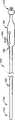
图1A和1B是RF消融导管的侧面视图,该RF消融导管包括具有用于操纵本发明所述可塑形天线装置的操纵机构的一个实施例的手柄。1A and 1B are side views of an RF ablation catheter including a handle with one embodiment of a steering mechanism for manipulating the morphable antenna device of the present invention.
图2A和2B是RF消融导管的侧面视图,该RF消融导管包括具有用于操纵本发明所述可塑形天线装置的操纵机构的另一个实施例的手柄。2A and 2B are side views of an RF ablation catheter including a handle with another embodiment of a steering mechanism for manipulating the morphable antenna device of the present invention.
图3A和3B是本发明所述可塑形天线装置处于笔直构型和塑造构型时的一个实施例的侧面剖视图。3A and 3B are side cross-sectional views of one embodiment of the morphable antenna assembly of the present invention in a straight configuration and in a molded configuration.
图4A和4B是本发明所述可塑形天线装置处于笔直构型和塑造构型时的另一个实施例的侧面剖视图。4A and 4B are side cross-sectional views of another embodiment of the morphable antenna assembly of the present invention in a straight configuration and a molded configuration.
图5A和5B是本发明所述可塑形天线装置处于笔直构型和塑造构型时的又一个实施例的侧面剖视图。5A and 5B are side cross-sectional views of yet another embodiment of the morphable antenna assembly of the present invention in a straight configuration and a molded configuration.
图6A和6B是本发明所述可塑形天线装置处于笔直构型和塑造构型时的还一个实施例的侧面剖视图。6A and 6B are side cross-sectional views of yet another embodiment of the morphable antenna assembly of the present invention in a straight configuration and a molded configuration.
图7A-7C是图5A、5B和图6A、6B所示可塑形天线装置实施例的预塑形偏转件和偏转调整件的备选实施例。7A-7C are alternative embodiments of pre-shaped deflection members and deflection adjustment members of the embodiment of the shapeable antenna device shown in FIGS. 5A, 5B and 6A, 6B.
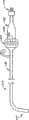
图8是RF消融导管的侧面视图,该RF消融导管包括依照本发明另一实施例构造的可塑形天线装置。8 is a side view of an RF ablation catheter including a shapeable antenna device constructed in accordance with another embodiment of the present invention.
图9A和9B是图8所示RF消融导管的可塑形天线装置的侧面剖视图。9A and 9B are side cross-sectional views of the shapeable antenna assembly of the RF ablation catheter shown in FIG. 8 .
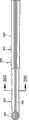
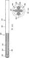
图10是依照本发明实施例的具有可偏转和操纵能力的射频导管的立体图。Figure 10 is a perspective view of a radio frequency catheter with deflectable and steerable capabilities in accordance with an embodiment of the present invention.
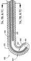
图11A是图10所示射频导管的远端部分的局部侧面剖视图,并且示出了可偏转导管导向件的一个实施例。11A is a partial side cross-sectional view of the distal portion of the radio frequency catheter shown in FIG. 10 and showing one embodiment of a deflectable catheter guide.
图11B是沿图11A中的线1iB-2B获取的横断面视图。FIG. 11B is a cross-sectional view taken along line 1iB-2B in FIG. 11A .
图11C是沿图11A中的线11C-11C获取的横断面视图。Fig. 11C is a cross-sectional view taken along line 11C-11C in Fig. 11A.
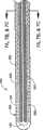
图12A是可偏转导管导向件的另一实施例的局部视图,其中导管导向件具有尺寸有变化的脊。12A is a partial view of another embodiment of a deflectable catheter guide with ridges of varying size.
图12B是图12A可偏转导管导向件的同一实施例的局部俯视图。12B is a partial top view of the same embodiment of the deflectable catheter guide of FIG. 12A.
图12C是沿图12B中的线12C-12C获取的横断面视图。Figure 12C is a cross-sectional view taken along
图12D是沿图12B中的线12D-12D获取的横断面视图。Figure 12D is a cross-sectional view taken along
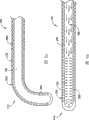
图13是设置在图10所示射频导管的远端部分的管腔内的图12B的可偏转导管导向件的局部视图。13 is a partial view of the deflectable catheter guide of FIG. 12B disposed within a lumen of the distal portion of the radiofrequency catheter shown in FIG. 10 .
图14是图13所示射频导管的远端部分处于偏转构型时的局部视图。14 is a partial view of the distal portion of the radiofrequency catheter shown in FIG. 13 in a deflected configuration.
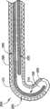
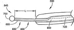
图15是射频导管的远端部分的另一实施例的局部侧面剖视图,并且示出了具有局部管状构造的柔性脊和在柔性脊的管腔内延伸的拉线筋的可偏转导管导向件的实施例。15 is a partial side cross-sectional view of another embodiment of a distal portion of a radio frequency catheter and showing an implementation of a deflectable catheter guide having a flexible spine of partial tubular configuration and a tendon extending within the lumen of the flexible spine example.
图16是图15所示射频导管的远端部分的局部侧视图,并且示出了具有朝着远端一侧向射频导管的远端部分延伸的导向件引导部分的可偏转导管导向件。16 is a partial side view of the distal portion of the radiofrequency catheter shown in FIG. 15 and showing a deflectable catheter guide having a guide guide portion extending towards the distal end of the radiofrequency catheter towards the distal end.
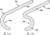
图17A和17B是射频导管的顺时针和逆时针预塑形的远端部分的示意图。17A and 17B are schematic illustrations of a clockwise and counterclockwise pre-shaped distal portion of an RF catheter.
图18A和18B是射频导管的顺时针和逆时针预塑形的远端部分的示意图,该射频导管包括有助于对远端部分进行塑形的拉线。18A and 18B are schematic illustrations of a clockwise and counterclockwise pre-shaped distal portion of a radiofrequency catheter including pull wires to aid in shaping the distal portion.
图19是射频导管实施例的局部侧面剖视图,该射频导管结合采用了可偏转导管导向件的实施例,可偏转导管导向件连接于滑动控制器用以偏转和操纵射频导管的远端部分。19 is a partial side cross-sectional view of an embodiment of an RF catheter incorporating an embodiment employing a deflectable catheter guide coupled to a slide controller for deflecting and steering the distal portion of the RF catheter.
图20A是具有双向偏转能力的可偏转导管导向件的另一实施例的局部俯视图。20A is a partial top view of another embodiment of a deflectable catheter guide with bi-directional deflection capability.
图20B是图20A可偏转导管导向件的同一实施例的局部正视图。Figure 20B is a partial front view of the same embodiment of the deflectable catheter guide of Figure 20A.
图20C是沿着图20A中剖线20C-20C获得的图20A的可偏转导管导向件的横截面视图。20C is a cross-sectional view of the deflectable catheter guide of FIG. 20A taken along
优选实施例详细说明Detailed Description of Preferred Embodiments
参看图1A和1B,其中示出了依照本发明一个实施例构造的包括可塑形天线装置110的射频(“RF”)消融导管100。导管100适用于插入病人的身体脉管内,而可塑形天线装置110包括用于将电磁能量传送给处置位点的射频天线。在说明本发明的可塑形天线装置之前,首先对导管100进行说明。Referring to Figures 1A and 1B, there is shown a radio frequency ("RF")
导管100包括柔软细长的管状体120,管状体120具有近端部分130和远端部分140。一个或多个腔内管腔150(图3A、3B)从导管100的近端部分130延伸到远端部分140。手柄底盘(handle chassis)160设置位于导管100的近端部分130,用于容纳所必需的操纵与定位控制机构,下面将进一步对此加以详细说明。连接头170结合形成在导管100的近端部分160,用于将导管100连接到一个或多个用以帮助实现消融处理的电子装置,如RF发生器和控制器(未示出)。
导管100的尺寸适合特定医疗手术所用,这是医学领域所公知的。在优选实施例中,导管100用于消融心脏组织;但是,导管100也可以用于消融其它类型的身体组织。导管的管状体120通常是由可在人体脉管环境中不会引起排斥反应的聚合体材料构造的。这些材料的例子包括但不局限于,来自德国的奥托凯姆(Autochem Germany)的Pebax、聚乙烯、聚氨酯、聚酯、聚酰亚胺和聚酰胺,这些材料的辐射不透过度、硬度和弹性各不相同。
导管100可以形成为采用一种或多种上述材料的多个片段,以便使得管状体120越是靠近其远端就具有越好的柔韧性。各段可通过热接、对接或粘接而结合到一起。还可以将编织层(braiding reinforcement)附加到管状体120的周边表面,以便使导管100达到所需的刚度和抗扭强度要求。这就使得导管100能够向前行进并成功地穿入病人的身体脉管,从而能够沿着导管长度将转动力矩从近端部分传送到远端部分。
另外参看图3A、B,管状体120的远端部分140可包括与近端部分130相比较软的聚合体化合物,带有一点编织套或不带有编织套,从而提供所需柔韧性以适应可塑形天线装置110的远端偏转和塑形。可塑形天线装置110的偏转和塑形可以通过使用预塑形偏转件180和偏转调整件190来实现。预塑形偏转件180和/或偏转调整件190可以从手柄底盘160延伸到导管体140的远端部分140。3A, B, the
预塑形偏转件180和/或偏转调整件190可以就近固定到偏转控制手柄或拇指滑动触头(thumb slide)200(图1A、1B),偏转控制手柄或拇指滑动触头200可以沿着手柄底盘160的轴向缝隙可滑动地啮合。沿着轴向隙缝对拇指滑动触头200进行轴向位移,使得医师能够对可塑形天线装置110进行塑形或偏转,形成为直线构型(图1A)以及偏转构型(图1B)、或者介于两者之间的任意其它构型。可在拇指滑动触头200中结合形成摩擦保持机构(未示出),用以保持手柄在轴向隙缝中的位置。许多这种装置都可以从市场上获取到。这种装置的例子包括擒纵装置(set-release)、压力操纵开关或自锁机构。The
图2A和2B显示了RF消融导管210,其与前述RF消融导管100相似,但是带有偏转控制机构220的可选实施例,偏转控制机构220用以对可塑形天线装置110进行塑形或偏转。偏转控制机构220可包括可转动卡圈(collar)230,可转动卡圈230沿圆周环绕着手柄底盘160的手柄杆240并且可旋转地与手柄杆240耦合连接,用以控制预塑形偏转件180和/或偏转调整件190的轴向位移。手柄底盘160可容纳有转换机构,用以将卡圈230的转动转换为预塑形偏转件180和/或偏转调整件190的轴向位移。卡圈230相对于手柄杆240的转动使得医师能够以直线构型(图2A)和偏转构型(图2B)或介于其间的任意形状对可塑形天线装置110进行塑形或偏转。2A and 2B show an
参看图3A和3B,现在将对可塑形天线装置110的一个实施例进行详细说明。导管体140的远端部分包括RF天线250,RF天线250具有用于身体组织消融的柔性螺旋形线圈状的RF辐射天线元件255。在一个代表性的实施例中,RF天线250包括呈螺旋状环绕形成螺旋线圈绕组的电导材料或导线条。线圈绕组的适当的直径、节距和长度,以及电导材料或导线条的选择,都是设计选择因素,可根据特定手术和柔韧性要求来改变这些因素。Referring to Figures 3A and 3B, one embodiment of the
RF天线250适合用于接收和辐射来自射频能量源(未示出)的电磁能。例如,合适的射频谱是通常大于300MHz的微波频段。RF天线250能够沿RF天线250施加基本上均匀分布的电磁场能量,其与RF天线250和待消融组织之间的接触无关。发射的电磁场基本上垂直于RF天线250的纵轴,且因此产生环绕RF天线250分布并由RF天线250限定的均匀能量场。
RF天线250可与一个或多个电导体260电接触,电导体260又可与RF能量源电连接。例如,该一个或多个电导体260可以,但不局限于,由柔性网或编织线结构制成,或者由薄膜电导材料制成,其近似地从RF天线250延伸到手柄底盘160。如下面参照图11A-11C所进行的详细说明,该一个或多个电导体260优选地包括细长的、共轴的、周边对准的内导体640和外导体660。内导体640可包括或周边环绕同轴套件630。套件630的内表面限定出管腔150。The
RF天线250和该一个或多个电导体260可以沿着它们的长度走向涂覆聚合体电介质密封剂、涂料、或层,以确保结构的完整性,从而保护其不受生物环境影响,隔离电部件,且有助于将电磁场限制在可塑形天线装置110之外。该密封剂、涂料、或层可以由合适材料制成,例如硅或聚合物基材料或者橡胶化合物。The
偏转调整件190可以是与预塑形偏转件180共轴、并且可滑移地安装在预塑形偏转件180之上的鞘套。偏转调整件190优选地具有细长的、笔直的管状构型,并且可由塑料或金属柔性材料制成。偏转调整件190可以预先塑形为所希望的构型。
预塑形偏转件180可以是预先塑形成所需构型的细长的、柔韧的线或脊。预塑形偏转件180可由金属材料(例如双金属或形状记忆合金(“SMA”)材料)或者具有适当程度的记忆、生物适应性以及类似于弹簧的结构特性的聚合体材料。这种材料例如是,但不局限于,镍-钛合金(以镍钛诺(nitinol)商标售卖)、不锈钢、聚酰胺、以及聚四氟乙烯(“PTFE”)。所用金属材料也可以根据需要做加热处理或冷却,以提供理想的结构特性,如刚度和柔韧性。只有远端部分270或整个预塑形偏转件180可以被预先塑形或由预塑形材料制成。使用预塑形材料能够对预塑形偏转件180或偏转调整件190进行预塑形,以使可塑形天线装置110与所需的直线或曲线轮廓相一致,因此,有助于优化可塑形天线装置110结构和沿循目标位点处的内部轮廓线或几何结构来放置可塑形天线装置110。
在如图3A、3B所示的可塑形天线装置110实施例中,通过向远端滑动预塑形偏转件180而使预塑形偏转件180滑出偏转调整件190(经由手柄底盘160处的偏转控制机构)并进入管腔150,就可使可塑形天线装置110的形状由预塑形偏转件180规定。3A, 3B, the
可以通过可塑形天线装置110带有的一个或多个射频不透过标记(未示出)来实现可塑形天线装置110的正确塑形和放置。利用一个或多个射频不透过标记,可塑形天线装置110在用x射线或荧光检测时变得不透明,因此有助于在塑形和放置用以组织消融的可塑形天线装置110的过程中识别其位置。Proper shaping and placement of the
此外,可塑形天线装置110可以携带一个或多个心脏内部心电图(“ECG”)电极(未示出),用以帮助医师获取最佳的组织接近度并获取组织消融前后的电导活性,以及获取它们动作的反馈。这些电极可以固定在可塑形天线装置110的长度方向上。Additionally, the
参看图4A,其中显示了可塑形天线装置280的另一实施例,与图4A相类似,可塑形天线装置280的形状由预塑形偏转件180规定。但是,在这个实施例中,通过可滑移地朝着近端一侧方向缩回偏转调整件190从而使偏转调整件190远离预塑形偏转件180远端部分270,使预塑形偏转件180对可塑形天线装置280进行塑形以达到理想构型。这就使得远端部分270呈现为预先设定形状,而后使得可塑形天线装置280达成理想构型。Referring to FIG. 4A , another embodiment of a
图5A、5B和图6A、6B还分别描述了可塑形天线装置290、300呈现为直线形状时和塑型形状时的各个实施例。在图5A、5B中,可塑形天线装置290与上述图3A、3B所示的可塑形天线装置110类似之处在于,可塑形天线装置290通过轴向滑移预塑形偏转件320的远端部分310而远离偏转调整件330的远端从而达到所期望的构型。在图6A、6B中,可塑形天线装置300与上述图4A、4B所示的可塑形天线装置280的类似之处在于,可塑形天线装置300通过轴向滑移偏转调整件340以使其接近预塑形偏转件360的远端部分350从而达到所期望的构型。Figures 5A, 5B and Figures 6A, 6B also describe various embodiments when the
参看图7A-7C,其中示出了可以用于图5A、5B和图6A、6B所示的可塑形天线装置290、300的偏转调整件330、340和预塑形偏转件320、360的一些典型实施例。Referring to Figures 7A-7C, some of the
在图7A中,预塑形偏转件320、360具有窄的通常为矩形的截面,而相邻的偏转调整件330、340则具有较宽的通常为矩形的截面。在这个实施例中,预塑形偏转件320、360和偏转调整件330、340彼此平行,并且可以沿它们的长度而彼此接触。预塑形偏转件320、360和/或偏转调整件330、340可以可滑动地容纳于套件(未示出)中,以确保在对可塑形天线装置290、300进行塑形之前由偏转调整件330、340将预塑形偏转件320、360保持为直线构型(或者其它所希望的构型)。In FIG. 7A, the
在图7B中,偏转调整件330、340具有通常为方块C-形的截面,而相邻的预塑形偏转件320、360具有通常为矩形的截面。在这个实施例中,预塑形偏转件320、360可滑动地容纳于偏转调整件330、340中。In FIG. 7B, the
在图7C中,偏转调整件330、340具有通常为曲线C-形的截面,而相邻的预塑形偏转件320、360具有通常为圆形的截面。在这个实施例中,预塑形偏转件320、360可滑动地容纳于偏转调整件330、340中。In FIG. 7C, the
以下将参照图8对依照本发明另一实施例构造的包括可塑形天线装置410的RF消融导管400进行说明。RF消融导管400与上面图1A、1B和2A、2B所示导管100相类似,只是可塑形天线装置410的形状是由液压的或气动的流体压力调整而非由偏转调整件190调整的。在导管400的近端,可使用锁闭开关420连接导管400和液压的或气动的流体压力源430。在所示实施例中,流体压力源430是充有流体(例如盐水)的注射器,但是,在另选实施例中,流体压力源430可以是泵或其它另选的流体压力源。An
另外参看图9A、9B,诸如上述图4A、4B所示的预塑形偏转件180的预塑形偏转件可以被完全配置或集成到可塑形天线装置410中,因此可塑形天线装置410可以呈现出如图9A所示的预塑形偏转件180的形状。预塑形偏转件180可以设置在导管400的一个或多个管腔150中,可以设置在天线250中,可以设置在导管体120的壁中,或者导管体120可以被预先塑形。为了使可塑形天线装置410变直为如图9B所示的形状,可以由流体压力源430将流体压力给送到导管400的远端部分140的内部。例如,在锁闭开关420的阀处于打开位置的情况下,可以压按注射器流体压力源的柱塞,致使流体从注射器注入到导管体120的远端部分140。这就使得施加到可塑形天线装置410中的压力通常沿着图示压力箭头方向分布,使得预塑形的可塑形天线装置410伸直。通过关闭锁闭开关420上的阀以使导管体120中的流体不能逸出导管体120,就可使可塑形天线装置410保持如图9B所示的伸直形状。为了使可塑形天线装置410回复到如图9A所示的形状,可以打开锁闭开关420上的阀以使注射器流体压力源430的柱塞缩退回来。这样就消除了导管体120远端部分140中的流体,而可塑形天线装置410就回复了预塑形偏转件的形状。因此,可塑形天线装置410中的流体压力起到了与上述偏转调整件同样的作用,而对可塑形天线装置的流体压力控制(例如,通过注射器流体压力源430和锁闭开关420)相当于偏转控制机构。Referring additionally to Figures 9A, 9B, a pre-shaped deflector such as the
在另一实施例中,其中预塑形偏转件180设置在天线250上,设置在导管体120的壁中,或导管体120是预塑形的,诸如偏转调整件190的偏转调整件能够可滑移地容纳在细长管腔150中用以对可塑形天线装置的偏转进行调整。In another embodiment, in which the
现在将对可塑形天线装置的使用情况进行大致介绍。通过开口将导管插入病人身体脉管中,伸入到要消融的目标组织附近。在插入之前,可塑形天线装置设置为笔直形状。一旦插入,操纵导管的远端部分140以抵达需要消融的位置附近。可以使用导管的操纵装置来操纵导管通过病人的脉管系统到达目标消融位点,并且/或者可以利用上述的可塑形天线装置和偏转控制机构来实现操纵导管的远端部分140到达目标消融位点。利用拇指滑动触头200、可转动卡圈230,或通过控制给可塑形天线装置的流体压力(例如,利用导管400),来实现方向控制。A general introduction to the use of the shapeable antenna device will now be given. A catheter is inserted through the opening into a vessel in the patient's body and into the vicinity of the target tissue to be ablated. Prior to insertion, the shapeable antenna assembly is set into a straight shape. Once inserted, the
设置在导管的远端部分140上的一个或多个射频不透过标记可有助于可塑形天线装置的放置、塑形和偏转。如本领域所公知的那样,通过适当的x射线或荧光装置可以检测出该一个或多个射频不透过标记的位置。在将导管的远端部分140放置到组织消融位点附近之后,可以通过上述任意对可塑形天线装置的塑形方法将可塑形天线装置塑形为所希望的形状(例如,朝着偏转调整件的远侧方向展开(deploying)预塑形偏转件由此使可塑形天线装置呈现为预塑形偏转件的远端部分的形状,向着预塑形偏转件远端部分的近侧方向收撤缩回预塑形偏转件由此使可塑形天线装置呈现为预塑形偏转件的远端部分的形状,释放消除导管远端部分140的流体压力由此使可塑形天线装置呈现为预塑形偏转件的远端部分的形状)。操纵可塑形天线装置以达到所希望形状,从而使对目标体组织的消融达到最佳效果。使用心脏内ECG电极可进一步有助于使RF天线250对准目标消融位点。One or more radio-opaque markers disposed on the
举个例子,在对象为心房的情况下,可以调整可塑形天线装置的形状以适合心房内壁的轮廓起伏,以便让至少一部分可塑形天线装置搁放到心房壁上,形成心房和可塑形天线装置之间的线接触。可塑形天线装置足够柔韧,以便让至少一部分可塑形天线装置适合身体脉管的内部轮廓并且搁放抵靠其内壁。当心房壁脉动时,与心房壁接触的可塑形天线装置也将一齐移动,因此与希望进行处理的身体脉管部位形成贴附且稳定的关系。For example, where the subject is an atrium, the shape of the shapeable antenna device can be adjusted to fit the contour undulations of the inner wall of the atrium, so that at least a portion of the shapeable antenna device rests on the wall of the atrium to form the atrium and the shapeable antenna device line contact between. The shapeable antenna device is flexible enough to allow at least a portion of the shapeable antenna device to conform to the inner contour of a body vessel and to rest against the inner wall thereof. As the atrial wall pulsates, the shapeable antenna assembly in contact with the atrial wall also moves in unison, thus forming an affixed and stable relationship with the desired body vascular site to be treated.
一旦当可塑形天线装置已达成所希望的塑造外形并且平行对准所希望消融路径,则可塑形天线装置的形状就会被在适当的位置稳固下来(例如,利用擒纵装置、压力操纵开关、自锁机构,将锁闭开关420的阀移到关闭位置上)。之后,通过施用射频能量可实现组织消融。根据特定的方法步骤要求,可通过在施用RF能量之后随即沿着各种目标组织位置对RF天线进行定位来调整消融的长度。因此,易于形成长而连续的消融线,从而消除了在已消融的组织路径之间电脉冲泄露的危险。Once the shapeable antenna assembly has achieved the desired contour and is aligned parallel to the desired ablation path, the shape of the shapeable antenna assembly is stabilized in place (e.g., using escapements, pressure-operated switches, The self-locking mechanism moves the valve of the
上述这些过程可以对心房内其它位置或特定手术要求所需的身体其它部位进行重复或加以执行。These procedures described above can be repeated or performed at other locations within the atrium or other parts of the body as required by specific surgical requirements.
通过上述说明,显而易见,本发明的可塑形天线装置能够使电极快速、便捷而准确地到达目标组织上的最佳位置,并且在施加RF能量给目标组织实施治疗期间保持稳定。From the above description, it is obvious that the shapeable antenna device of the present invention can make the electrode reach the optimal position on the target tissue quickly, conveniently and accurately, and keep stable during the application of RF energy to the target tissue for treatment.
以下将参照图10-11C对用于消融身体脉管(例如但不限于病人的心脏)的生物组织的射频导管500的另一实施例进行说明。导管500适合插入到身体的脉管内,且包括可偏转的导管导向件510,导向件510设置位于导管管腔520内。除了上述可塑形天线装置之外可将可偏转导管导向件510设置位于导管500内。另选地,导管500可包括可偏转导管导向件510而不包括可塑形天线装置。射频或微波天线530设置在导管500的远端部分540。天线530接收并发射用于组织消融的射频(微波)能量。Another embodiment of a
导管导向件510规定了用于组织消融的天线530的消融路径。在本发明的典型实施例中,导管导向件510包括与导管手柄570的滑动控制机构560相连接的细长部分,导管手柄570的滑动控制机构560处于身体脉管的外面,用于偏转、操纵、定位与展开(deployment)控制。
连接缆线580从导管手柄570的近端590延伸而出,且包括电接插件或电连接件600,用于连接导管500与一个或多个集成的和/或分立的电子装置,例如但不限于RF发生器、ECG系统以及用于消融处理的控制器(未示出)。A
导管位置控制器610可从导管手柄570的近端590延伸而出,用于操纵导管500进入病人的脉管和/或用于控制导管导向件510的轴向移动。
RF天线530可包括以螺旋形式盘绕形成柔性螺旋线圈620的导电材料或导线条带。线圈绕组的适当的直径、节距和长度以及电导材料或导线条的选择,都是设计选择因素,可根据特定手术和柔韧性要求来改变这些因素。
为了提高其外形的完整性,RF天线530设置有内管、管状衬套或套件630,其具有从螺旋线圈620朝着近端一侧向导管500的手柄570延伸的柔性的延伸体。套件630由电介质材料构成,其降低了螺旋线圈620金属表面和管腔520内体液之间短路的风险,并且有助于将电磁场限制在管腔520之外。To improve the integrity of its shape, the
螺旋线圈620与第一导体或内导体640电连接,第一导体或内导体640又通过电连接件600与RF能量源连接。内导体640由柔性网或编织线结构制成,或者由薄膜导电材料制成,其外接于套件630的外表面,且从螺旋线圈620朝着近端一侧向手柄570延伸。在这个实施例中,内导体640呈现为细长的管状结构形状。套件630的内壁限定了管腔520。
内导体640沿其外周缘表面涂覆有聚合体电介质保护涂料或层650,并向近端一侧延伸到手柄570。电介质层650用做第二导体或外导体660的衬底,且将内导体640和外导体660电隔离。
螺旋线圈620缠绕在电介质层650的外周缘表面上,且电连接到外导体660。而后,外导体660电连接到RF能量源。The
在图示的实施例中,外导体660由导电材料制成,其外接于电介质层650周围,且从螺旋线圈620朝着近端一侧伸向手柄570延伸。外导体660可由编织线结构或薄膜导电材料制成。In the illustrated embodiment, the
螺旋线圈620可沿其外周缘表面涂覆聚合体电介质密封剂,用以确保螺旋线圈620的结构整体性,并且用以保护其不受生物环境的侵害。该密封剂由合适材料制成,例如硅或聚合体基材料或者橡胶化合物。The
类似地,由相同材料制成的外壳670被提供用于包裹螺旋线圈620和外导体660,从而提供与生物环境之间的电磁隔离和热隔离。Similarly, a
因此,导管500的远端部分540包括一组电导体,每个电导体都构造为细长管状形状,并且彼此以基本上共轴且周边对准的方式排列,从而形成从螺旋线圈620朝着近端一侧向手柄570延伸的用以传送RF能量的空心电缆。这种结构的优越性在于,因为管状导体640、660(其可为螺旋缠绕形式)和螺旋线圈天线530使导电表面面积最大化,且因此,使微波能量传送效率最大化,而且具有容纳导管导向件和/或可塑形天线装置的中心共轴管腔。尽管图示给出的管腔520是与导体640、660共轴的,但在另选实施例中,管腔520可以包括一个或多个管腔,该一个或多个管腔可以不与导体640、660共轴。Accordingly, the
导管导向件510可以从位于身体脉管中的导管500纵向展开并且可以柔性地顺应身体脉管的轮廓起伏。利用一个或多个射频不透过标记以及沿导管导向件510安设的心内电极,可有助于将导管导向件510对准所希望的组织消融路径。在一个另选实施例中,可以使导管导向件500相对于导管500固定。
导管导向件510包括细长柔性脊(spine)680,该细长柔性脊680具有包含远端防损端头(atraumatic tip)700在内的远端部分690。远端部分690可连接到位于导管500远端的天线530的远端部分,使得防损端头700与天线530相邻。在一个另选实施例中,导管导向件510可固定到导管500,以使得防损端头700从导管500端部延伸一段距离。
端头700是防损的,从而减少了刺戳身体组织的可能性。任选地,由不透过辐射的材料制成防损端头700,从而有助于在实施消融术期间识别天线530的位置。
脊680由一个或多个类似于弹簧的柔性材料制成。举例来说,在本发明的一个实施例中,脊680由不锈钢制成。在本发明的另一个实施例中,脊680是由多个细长元件构成的,这些细长元件具有预先设定的尺寸大小并且连接形成一个整体。可将脊680的近端部分固定至滑动控制机构560。
在脊680的另一个实施例中,脊680的远端部分690比脊680的其余部分更为柔韧,即,脊680至少在其部分长度上具有可变的刚度。这种柔韧性的差异可以通过改变脊680的横截剖面的形状和大小来获取。In another embodiment of the
在脊680的另一个实施例中,至少脊680的远端部分690是由双金属或形状记忆合金(“SMA”)材料制成的,例如以镍钛诺(nitinol)商标售卖的镍钛合金。另选地,整个脊680或者与远端部分690相比更大的一部分脊680是由这种SMA材料制成的。使用SMA材料能够确保导管导向件510或导管500的远端部分540的预塑形与导管体一致从而达到所希望的曲线轮廓,因此有助于根据身体脉管的内轮廓或几何结构来导引和放置导管500。SMA材料预塑形的装置和方法是本领域所公知的,因而不在此进行详细讨论。In another embodiment of the
图17A和17B显示了导管导向件510预塑形的应用实例。在图17A中,脊680如图所示具有预塑形的逆时针方向的钩或弯。在图17B中,脊680如图所示具有预塑形的顺时针方向的钩或弯。Figures 17A and 17B show an example application of
下面将参照图12A-19对导管导向件710的另一实施例进行说明。导管导向件710包括脊680、防损端头700以及第二细长条带或拉线筋(pullwire tendon)720,拉线筋720在导管管腔520内沿着脊680长度方向延伸分布。拉线筋720由弹性的类似弹簧的材料构成。拉线筋720也可以由SMA材料构成,其任选地可被预先塑形为适合内部身体脉管的特定几何形状要求的样子。拉线筋720的远端部分固定于防损端头700。脊680的远端部分690也固定在此位置上。拉线筋720的近端部分730(图19)可通过接合件760固定于滑动控制机构750的拇指滑动触头740。拇指滑动触头740可以沿着手柄570的手柄套780的纵向隙缝770滑动地啮合。拇指滑动触头740沿纵向隙缝770的纵向移动可确保医师能够偏转导管导向件的远端部分690。可在拇指滑动触头740中结合形成摩擦保持机构(未示出),用以保持手柄在纵向隙缝770中的夹持位置。许多这种装置都可以从市场上获取到。这种装置的例子包括擒纵装置、压力操纵开关或自锁机构。Another embodiment of a
脊680的近端部分790在电接点800处连接到手柄570。电接点800设置在电导体810的远端部分。ECG导体820从电接点800起延伸穿过连接缆线580,用以在外部ECG系统和位于导管500远端部分540的一个或多个ECG电极之间传送ECG信号。一个或多个附加导体可延伸穿过连接缆线580,用以连接导管500的电学特征和一个或多个外部电学系统。连接缆线580包括有绝缘外壳830并且终止于电连接件600,电连接件600用于连接导管500和一个或多个外部电学系统。
特别参看图12A-14,脊680的远端部分690可比脊680的近端部分840更为柔韧。这种柔韧性的差异可以通过改变脊680的横截剖面的形状和大小来获取。例如,脊680的远端部分690可具有横截面宽度W1和厚度T1,而脊680的近端部分840可具有横截面宽度W2和厚度T2。在所示实施例中,远端部分690的横截面宽度W1宽而远端部分690的厚度T1窄,而近端部分840的横截面宽度W2窄而近端部分840的厚度T2宽。这种结构连同如图所示的拉线筋720的定向可致使脊680的远端部分690与近端部分840相比更为柔韧。Referring specifically to FIGS. 12A-14 , the
图13和14分别显示了导管500的远端部分540处于笔直构型和偏转构型时的情形。在图13所示的笔直构型中,拉线筋720没有拉拽防损端头700。在图14所示的偏转构型中,在拉线筋720拉拽防损端头700的作用下导管导向件710被偏转或者弯曲。13 and 14 show the
如上文结合图17A和17B所述,脊680的远端部分690可由双金属或形状记忆合金(“SMA”)材料制成,以确保导管导向件710或导管500的远端部分540的预塑形与导管体一致从而达到所希望的直线轮廓。图18A和18B显示了导管导向件710的预塑形结构的应用实例。在图18A中,脊680如图所示具有预塑形的逆时针方向的钩或弯。在图18B中,脊680如图所示具有预塑形的顺时针方向的钩或弯。通过滑动控制机构750使拉线筋720纵向移动,可让导管导向件710和导管500的远端部分690呈现出预塑形构型或笔直构型。As described above in connection with FIGS. 17A and 17B , the
参看图15和16,其中示出了导管导向件845的一个另选实施例。在这个实施例中,导管导向件845包括细长的管状体850,管状体850在其大部分或整个长度上环绕并包裹了脊680和拉线筋740。细长管状体850的远端部分860可具有近于环状的剖露出脊680和拉线筋720的横截面。细长管状体850包括管状管腔870,脊680和拉线筋720从中延伸穿过。Referring to Figures 15 and 16, an alternative embodiment of a
在图16中,导管导向件845的远端部分向远侧延伸超出导管体的端部以限定出导向件引导部分(guide leader)880。导向件引导部分880的长度L可根据由RF天线530和防损端头700之间的相对位置或距离定义的具体应用而变化。防损端头700用于锚固导管500。可预先确定导向件引导部分880的长度L并在制造导管500的过程中使长度L固定。另选地,可对导向件引导部分880的长度L进行调整,并且一旦达到所希望的长度L,则锁定滑动控制机构以防止导向件引导部分长度L改变。在一个典型实施例中,导向件引导部分880具有大约3厘米的长度L。In FIG. 16 , the distal end portion of
在应用中,导管导向件845用于建立与身体脉管表面的定位和接触。通过防损的远端端头700将导管500(和螺旋天线530)锚固到身体脉管上,减小了刺穿的风险。导管导向件845的柔韧性使其能够挠曲以适应身体脉管的轮廓起伏,从而确保射频天线或微波天线530的消融路径安全可靠。可偏转导管导向件845设置位于管腔520中,导管500的远端部分540与导管导向件845的直线构型适应一致。拉线筋720与导管导向件845的防损端头700相连,进一步提供了对导管导向件845的操纵能力。在滑动控制机构750处单独对脊680和拉线筋720进行操控或者成对(或远端或近端地)操控,进一步提供了对导管导向件845的形状改变(且因此导管500地远端部分540形状改变)和操纵方向改变。因此,除了提供对导管导向件845的预塑形(且因此,导管500的远端部分540被预塑形)之外,导管100还提供了在身体脉管中的基本性能和通用性。In application,
任选地,可将一个或多个心内心电图(“ECG”)电极安设在导管导向件845之上或之中,以帮助收集使用导管100时的心内电信号。Optionally, one or more intracardiac electrographic ("ECG") electrodes may be mounted on or in
下面将参照图20A-20C对采用双向偏转控制的导管导向件900的实施例加以说明。导管导向件900与上述导管导向件710相类似,只是导管导向件900包括有一对相对设置的拉线筋930、940,拉线筋930、940是沿着导管导向件900的长度方向延伸设置,用以提供对管腔950中的脊915的双向偏转或操纵。拉线筋930、940可滑动地设置在细长筋槽(tendon grooves)960中。可将拉线筋930、940的远端可固定至防损端头970。脊915包括塑形的半柔性脊920和平的柔性脊910,半柔性脊920延伸占据了脊915的大部分长度,而平的柔性脊910则位于脊915的远端部分且从塑形的半柔性脊920的远端980延伸。平的柔性脊910和塑形的半柔性脊920可由上述针对脊680的任意材料以及适于本文所述应用的所有其它材料或材料混合物(例如,金属、聚合物)制成。拉线筋930、940的近端可与滑动控制机构相连接,用以控制拉线筋930、940的移动,且因此控制导管导向件900的偏转。An embodiment of a
使用中,滑动控制机构的驱动可导致一个拉线筋930拉拽防损端头970。这就导致脊915朝筋930的方向弯曲或偏转。同样,滑动控制机构的驱动还可导致相对的侧拉线筋940以相反方向拉拽防损端头970。导管导向件900的双向偏转控制给医师提供了更多对导管远端部分构型的控制。尽管前面描述的是单向偏转控制和双向偏转控制,但可对导管导向件900进行构造以实现其它数目个方向的控制(例如:三个方向的偏转控制,等等)。In use, actuation of the slide control mechanism may cause one of the
由上述说明,显而易见本发明不仅有效减少了(若不能避免的话)对消融导管天线的重复性精确定位的高精度放置要求(如现有技术的做法),而且还为在身体脉管中使用天线530提供了基本导引能力。本发明方便地沿着限定出组织消融路径的导管导向件轨迹来放置射频天线530。同时,本发明确保消融路径连续并且实际上减少了消融位点之间电脉冲泄露(如现有技术所表现的那样)的风险。因此,本发明实质上是无须进行开心手术就实现了梅兹(Maze)法获取曲线伤痕的目的。本发明的这些和其它方面的特征以及优点通常下面的详细说明和附图将变得更加明晰,这些附图通过示例说明了本发明的技术特征。From the above description, it is apparent that the present invention not only effectively reduces, if not avoids, the high precision placement requirement for repeatable precise positioning of the ablation catheter antenna (as is done in the prior art), but also provides a new path for the use of the antenna in body vessels. The 530 provides basic guidance capabilities. The present invention conveniently places the
对本领域普通技术人员而言显而易见的是,可以容易地对本发明所述实际思路做进一步的改变或变型,但这不会背离本发明如后面的权利要求书所限定的精神和范围。It will be apparent to those skilled in the art that further changes or modifications can easily be made to the practical concepts of the invention without departing from the spirit and scope of the invention as defined in the following claims.
Claims (26)
Applications Claiming Priority (2)
| Application Number | Priority Date | Filing Date | Title |
|---|---|---|---|
| US33419901P | 2001-11-29 | 2001-11-29 | |
| US60/334,199 | 2001-11-29 |
Publications (2)
| Publication Number | Publication Date |
|---|---|
| CN1625371A CN1625371A (en) | 2005-06-08 |
| CN100508910Ctrue CN100508910C (en) | 2009-07-08 |
Family
ID=23306064
Family Applications (1)
| Application Number | Title | Priority Date | Filing Date |
|---|---|---|---|
| CNB028261488AExpired - LifetimeCN100508910C (en) | 2001-11-29 | 2002-11-27 | Radio frequency based catheter system with improved deflection and steering mechanism |
Country Status (9)
| Country | Link |
|---|---|
| US (3) | US7004938B2 (en) |
| EP (1) | EP1460954B1 (en) |
| JP (1) | JP2005511135A (en) |
| CN (1) | CN100508910C (en) |
| AT (1) | ATE375127T1 (en) |
| AU (1) | AU2002365882A1 (en) |
| CA (1) | CA2468531C (en) |
| DE (1) | DE60222934T2 (en) |
| WO (1) | WO2003047448A1 (en) |
Cited By (1)
| Publication number | Priority date | Publication date | Assignee | Title |
|---|---|---|---|---|
| CN104411264A (en)* | 2012-10-02 | 2015-03-11 | 柯惠有限合伙公司 | Selectively deformable ablation device |
Families Citing this family (137)
| Publication number | Priority date | Publication date | Assignee | Title |
|---|---|---|---|---|
| US6302880B1 (en)* | 1996-04-08 | 2001-10-16 | Cardima, Inc. | Linear ablation assembly |
| US6702789B1 (en) | 1997-03-11 | 2004-03-09 | Alcove Medical, Inc. | Catheter having insertion control mechanism and anti-bunching mechanism |
| US6096037A (en) | 1997-07-29 | 2000-08-01 | Medtronic, Inc. | Tissue sealing electrosurgery device and methods of sealing tissue |
| US20070066972A1 (en)* | 2001-11-29 | 2007-03-22 | Medwaves, Inc. | Ablation catheter apparatus with one or more electrodes |
| US7594913B2 (en)* | 1998-12-14 | 2009-09-29 | Medwaves, Inc. | Radio-frequency based catheter system and method for ablating biological tissues |
| US20060095032A1 (en) | 1999-11-16 | 2006-05-04 | Jerome Jackson | Methods and systems for determining physiologic characteristics for treatment of the esophagus |
| US20040215235A1 (en) | 1999-11-16 | 2004-10-28 | Barrx, Inc. | Methods and systems for determining physiologic characteristics for treatment of the esophagus |
| US6447443B1 (en) | 2001-01-13 | 2002-09-10 | Medtronic, Inc. | Method for organ positioning and stabilization |
| US6932811B2 (en) | 2000-04-27 | 2005-08-23 | Atricure, Inc. | Transmural ablation device with integral EKG sensor |
| US6905498B2 (en) | 2000-04-27 | 2005-06-14 | Atricure Inc. | Transmural ablation device with EKG sensor and pacing electrode |
| US6546935B2 (en) | 2000-04-27 | 2003-04-15 | Atricure, Inc. | Method for transmural ablation |
| US20020107514A1 (en) | 2000-04-27 | 2002-08-08 | Hooven Michael D. | Transmural ablation device with parallel jaws |
| US7628780B2 (en) | 2001-01-13 | 2009-12-08 | Medtronic, Inc. | Devices and methods for interstitial injection of biologic agents into tissue |
| US7740623B2 (en) | 2001-01-13 | 2010-06-22 | Medtronic, Inc. | Devices and methods for interstitial injection of biologic agents into tissue |
| US20040138621A1 (en) | 2003-01-14 | 2004-07-15 | Jahns Scott E. | Devices and methods for interstitial injection of biologic agents into tissue |
| CN100508910C (en)* | 2001-11-29 | 2009-07-08 | 麦迪威公司 | Radio frequency based catheter system with improved deflection and steering mechanism |
| US8150519B2 (en) | 2002-04-08 | 2012-04-03 | Ardian, Inc. | Methods and apparatus for bilateral renal neuromodulation |
| US8774913B2 (en) | 2002-04-08 | 2014-07-08 | Medtronic Ardian Luxembourg S.A.R.L. | Methods and apparatus for intravasculary-induced neuromodulation |
| US7653438B2 (en) | 2002-04-08 | 2010-01-26 | Ardian, Inc. | Methods and apparatus for renal neuromodulation |
| US7572257B2 (en) | 2002-06-14 | 2009-08-11 | Ncontact Surgical, Inc. | Vacuum coagulation and dissection probes |
| US9439714B2 (en)* | 2003-04-29 | 2016-09-13 | Atricure, Inc. | Vacuum coagulation probes |
| US7063698B2 (en)* | 2002-06-14 | 2006-06-20 | Ncontact Surgical, Inc. | Vacuum coagulation probes |
| US6893442B2 (en) | 2002-06-14 | 2005-05-17 | Ablatrics, Inc. | Vacuum coagulation probe for atrial fibrillation treatment |
| US8235990B2 (en) | 2002-06-14 | 2012-08-07 | Ncontact Surgical, Inc. | Vacuum coagulation probes |
| US20040054350A1 (en)* | 2002-09-17 | 2004-03-18 | Shaughnessy Michael C. | Enteral feeding unit having a reflux device and reflux method |
| US7291161B2 (en) | 2002-10-02 | 2007-11-06 | Atricure, Inc. | Articulated clamping member |
| US20040116899A1 (en)* | 2002-12-16 | 2004-06-17 | Shaughnessy Michael C. | Bolus for non-occluding high flow enteral feeding tube |
| US7288092B2 (en) | 2003-04-23 | 2007-10-30 | Atricure, Inc. | Method and apparatus for ablating cardiac tissue with guide facility |
| US20050080471A1 (en)* | 2003-08-28 | 2005-04-14 | Yougandh Chitre | Lead body construction |
| US7150745B2 (en) | 2004-01-09 | 2006-12-19 | Barrx Medical, Inc. | Devices and methods for treatment of luminal tissue |
| US7530980B2 (en) | 2004-04-14 | 2009-05-12 | Atricure, Inc | Bipolar transmural ablation method and apparatus |
| WO2005120376A2 (en) | 2004-06-02 | 2005-12-22 | Medtronic, Inc. | Ablation device with jaws |
| US7976518B2 (en)* | 2005-01-13 | 2011-07-12 | Corpak Medsystems, Inc. | Tubing assembly and signal generator placement control device and method for use with catheter guidance systems |
| US20070060898A1 (en)* | 2005-09-07 | 2007-03-15 | Shaughnessy Michael C | Enteral medical treatment assembly having a safeguard against erroneous connection with an intravascular treatment system |
| US7997278B2 (en) | 2005-11-23 | 2011-08-16 | Barrx Medical, Inc. | Precision ablating method |
| US8702694B2 (en)* | 2005-11-23 | 2014-04-22 | Covidien Lp | Auto-aligning ablating device and method of use |
| US9833595B2 (en)* | 2005-12-30 | 2017-12-05 | Biosense Webster, Inc. | Dual-lever bi-directional handle |
| US10363092B2 (en) | 2006-03-24 | 2019-07-30 | Neuwave Medical, Inc. | Transmission line with heat transfer ability |
| US7890174B2 (en)* | 2006-06-02 | 2011-02-15 | Cardiac Pacemakers, Inc. | Medical electrical lead with deployable fixation features |
| US11389235B2 (en) | 2006-07-14 | 2022-07-19 | Neuwave Medical, Inc. | Energy delivery systems and uses thereof |
| US10376314B2 (en) | 2006-07-14 | 2019-08-13 | Neuwave Medical, Inc. | Energy delivery systems and uses thereof |
| DE102006034389B4 (en)* | 2006-07-25 | 2018-06-07 | Siemens Healthcare Gmbh | Catheter for use in magnetic resonance assisted interventional procedures |
| WO2008021321A2 (en) | 2006-08-17 | 2008-02-21 | Rjf Holdings Iv, Inc | Method and apparatus for plasma incision of cardiovascular tissue |
| US8197494B2 (en)* | 2006-09-08 | 2012-06-12 | Corpak Medsystems, Inc. | Medical device position guidance system with wireless connectivity between a noninvasive device and an invasive device |
| US20080094228A1 (en)* | 2006-10-12 | 2008-04-24 | Welch James P | Patient monitor using radio frequency identification tags |
| US20100286477A1 (en)* | 2009-05-08 | 2010-11-11 | Ouyang Xiaolong | Internal tissue visualization system comprising a rf-shielded visualization sensor module |
| JP5054116B2 (en)* | 2006-11-09 | 2012-10-24 | エヌコンタクト サージカル, インコーポレイテッド | Vacuum coagulation probe |
| US7643886B2 (en)* | 2007-01-25 | 2010-01-05 | Cardiac Pacemakers, Inc. | Hydraulic actuation of lead fixation member |
| US10932848B2 (en)* | 2007-02-06 | 2021-03-02 | Microcube, Llc | Delivery system for delivering a medical device to a location within a patient's body |
| EP2136714A4 (en)* | 2007-02-06 | 2013-04-03 | Microcube Llc | A delivery system for delivering a medical device to a location within a patient's body |
| US8641711B2 (en) | 2007-05-04 | 2014-02-04 | Covidien Lp | Method and apparatus for gastrointestinal tract ablation for treatment of obesity |
| US8157789B2 (en) | 2007-05-24 | 2012-04-17 | Endosense Sa | Touch sensing catheter |
| US8784338B2 (en) | 2007-06-22 | 2014-07-22 | Covidien Lp | Electrical means to normalize ablational energy transmission to a luminal tissue surface of varying size |
| CN102688092B (en)* | 2007-07-06 | 2015-04-22 | 柯惠有限合伙公司 | Ablation in the gastrointestinal tract to achieve hemostasis and eradicate lesions with a propensity for bleeding |
| WO2009009443A1 (en) | 2007-07-06 | 2009-01-15 | Barrx Medical, Inc. | Method and apparatus for gastrointestinal tract ablation to achieve loss of persistent and/or recurrent excess body weight following a weight-loss operation |
| US8273012B2 (en) | 2007-07-30 | 2012-09-25 | Tyco Healthcare Group, Lp | Cleaning device and methods |
| US8646460B2 (en)* | 2007-07-30 | 2014-02-11 | Covidien Lp | Cleaning device and methods |
| US20090082762A1 (en)* | 2007-09-20 | 2009-03-26 | Ormsby Theodore C | Radio frequency energy transmission device for the ablation of biological tissues |
| US8133222B2 (en)* | 2008-05-28 | 2012-03-13 | Medwaves, Inc. | Tissue ablation apparatus and method using ultrasonic imaging |
| US20090318914A1 (en)* | 2008-06-18 | 2009-12-24 | Utley David S | System and method for ablational treatment of uterine cervical neoplasia |
| US8679106B2 (en)* | 2008-07-01 | 2014-03-25 | Medwaves, Inc. | Angioplasty and tissue ablation apparatus and method |
| US20100121139A1 (en) | 2008-11-12 | 2010-05-13 | Ouyang Xiaolong | Minimally Invasive Imaging Systems |
| US20110009694A1 (en)* | 2009-07-10 | 2011-01-13 | Schultz Eric E | Hand-held minimally dimensioned diagnostic device having integrated distal end visualization |
| US8652129B2 (en) | 2008-12-31 | 2014-02-18 | Medtronic Ardian Luxembourg S.A.R.L. | Apparatus, systems, and methods for achieving intravascular, thermally-induced renal neuromodulation |
| US9326819B2 (en)* | 2009-04-15 | 2016-05-03 | Medwaves, Inc. | Electrically tunable tissue ablation system and method |
| EP3549544B1 (en) | 2009-07-28 | 2021-01-06 | Neuwave Medical, Inc. | DEVICE FOR ABLATION |
| CN102711585B (en)* | 2009-11-02 | 2016-04-20 | 波士顿科学国际医疗贸易公司 | There is the soft endoscope that can change rigidity |
| US8469953B2 (en) | 2009-11-16 | 2013-06-25 | Covidien Lp | Twin sealing chamber hub |
| WO2011066445A2 (en)* | 2009-11-30 | 2011-06-03 | Medwaves, Inc. | Radio frequency ablation system with tracking sensor |
| US8870863B2 (en) | 2010-04-26 | 2014-10-28 | Medtronic Ardian Luxembourg S.A.R.L. | Catheter apparatuses, systems, and methods for renal neuromodulation |
| ES2856026T3 (en) | 2010-05-03 | 2021-09-27 | Neuwave Medical Inc | Power supply systems |
| US8672933B2 (en) | 2010-06-30 | 2014-03-18 | Covidien Lp | Microwave antenna having a reactively-loaded loop configuration |
| US8696620B2 (en) | 2010-07-30 | 2014-04-15 | St. Jude Medical, Atrial Fibrillation Division, Inc. | Catheter with a mechanism for omni-directional deflection of a catheter shaft |
| US9545253B2 (en) | 2010-09-24 | 2017-01-17 | Ethicon Endo-Surgery, Llc | Surgical instrument with contained dual helix actuator assembly |
| US9089327B2 (en) | 2010-09-24 | 2015-07-28 | Ethicon Endo-Surgery, Inc. | Surgical instrument with multi-phase trigger bias |
| US9220559B2 (en) | 2010-09-24 | 2015-12-29 | Ethicon Endo-Surgery, Inc. | Articulation joint features for articulating surgical device |
| US20120078244A1 (en) | 2010-09-24 | 2012-03-29 | Worrell Barry C | Control features for articulating surgical device |
| US9084610B2 (en) | 2010-10-21 | 2015-07-21 | Medtronic Ardian Luxembourg S.A.R.L. | Catheter apparatuses, systems, and methods for renal neuromodulation |
| KR101912960B1 (en) | 2010-10-25 | 2018-10-29 | 메드트로닉 아르디언 룩셈부르크 에스에이알엘 | Catheter Appratuses having Multi-Electrode Arrays for Renal Neuromodulation and Associated Systems and Methods |
| US9504518B2 (en) | 2010-11-29 | 2016-11-29 | Medtronic Ablation Frontiers Llc | System and method for adaptive RF ablation |
| US10278774B2 (en) | 2011-03-18 | 2019-05-07 | Covidien Lp | Selectively expandable operative element support structure and methods of use |
| EP2792322B1 (en) | 2011-08-25 | 2017-10-04 | Covidien LP | Systems and devices for treatment of luminal tissue |
| CN102551874B (en)* | 2011-10-20 | 2015-07-22 | 上海微创电生理医疗科技有限公司 | Renal artery radiofrequency ablation catheter |
| US9192438B2 (en) | 2011-12-21 | 2015-11-24 | Neuwave Medical, Inc. | Energy delivery systems and uses thereof |
| US9162036B2 (en) | 2011-12-30 | 2015-10-20 | Biosense Webster (Israel), Ltd. | Medical device control handle with multiple puller wires |
| US9345528B2 (en)* | 2012-01-27 | 2016-05-24 | Medtronic Cryocath Lp | Large area cryoablation catheter with multi-geometry tip ECG/CRYO mapping capabilities |
| WO2013142906A1 (en)* | 2012-03-27 | 2013-10-03 | Cathrx Ltd | An ablation catheter |
| CN107374723B (en) | 2012-05-11 | 2020-08-28 | 美敦力Af卢森堡有限责任公司 | Catheter apparatus |
| CN102688093B (en)* | 2012-06-20 | 2014-08-27 | 深圳市惠泰医疗器械有限公司 | Renal artery cold saline water radio frequency ablation controllable electrode catheter |
| CN104507408B (en) | 2012-06-22 | 2017-06-20 | 柯惠有限合伙公司 | For the microwave thermometric of microwave ablation system |
| US9993295B2 (en) | 2012-08-07 | 2018-06-12 | Covidien Lp | Microwave ablation catheter and method of utilizing the same |
| US9044575B2 (en) | 2012-10-22 | 2015-06-02 | Medtronic Adrian Luxembourg S.a.r.l. | Catheters with enhanced flexibility and associated devices, systems, and methods |
| ES2733273T3 (en) | 2012-10-22 | 2019-11-28 | Medtronic Ardian Luxembourg | Catheters with improved flexibility |
| US9233225B2 (en) | 2012-11-10 | 2016-01-12 | Curvo Medical, Inc. | Coaxial bi-directional catheter |
| US9549666B2 (en) | 2012-11-10 | 2017-01-24 | Curvo Medical, Inc. | Coaxial micro-endoscope |
| US9204921B2 (en) | 2012-12-13 | 2015-12-08 | Cook Medical Technologies Llc | RF energy controller and method for electrosurgical medical devices |
| US9364277B2 (en) | 2012-12-13 | 2016-06-14 | Cook Medical Technologies Llc | RF energy controller and method for electrosurgical medical devices |
| US10058310B2 (en) | 2013-03-13 | 2018-08-28 | Ethicon Llc | Electrosurgical device with drum-driven articulation |
| US9066726B2 (en) | 2013-03-15 | 2015-06-30 | Medtronic Ardian Luxembourg S.A.R.L. | Multi-electrode apposition judgment using pressure elements |
| US9987087B2 (en) | 2013-03-29 | 2018-06-05 | Covidien Lp | Step-down coaxial microwave ablation applicators and methods for manufacturing same |
| EP2996754B1 (en) | 2013-05-18 | 2023-04-26 | Medtronic Ardian Luxembourg S.à.r.l. | Neuromodulation catheters with shafts for enhanced flexibility and control and associated devices and systems |
| KR101459941B1 (en)* | 2013-08-23 | 2014-11-07 | 고려대학교 산학협력단 | Multi-electrode catheter for mapping and ablating lesion parts |
| US11547446B2 (en) | 2014-01-13 | 2023-01-10 | Trice Medical, Inc. | Fully integrated, disposable tissue visualization device |
| US10342579B2 (en) | 2014-01-13 | 2019-07-09 | Trice Medical, Inc. | Fully integrated, disposable tissue visualization device |
| US9370295B2 (en) | 2014-01-13 | 2016-06-21 | Trice Medical, Inc. | Fully integrated, disposable tissue visualization device |
| EP4253024B1 (en) | 2014-01-27 | 2025-02-26 | Medtronic Ireland Manufacturing Unlimited Company | Neuromodulation catheters having jacketed neuromodulation elements and related devices |
| US20160367314A1 (en)* | 2014-02-28 | 2016-12-22 | Tenjin LLC | Bendable and rebendable endoscopic electrosurgical device |
| DK3122414T3 (en) | 2014-03-26 | 2021-05-31 | Venclose Inc | Cable unit |
| CN106232043B (en) | 2014-04-24 | 2019-07-23 | 美敦力阿迪安卢森堡有限公司 | Nerve modulation conduit and relevant system and method with braiding axle |
| US10624697B2 (en) | 2014-08-26 | 2020-04-21 | Covidien Lp | Microwave ablation system |
| US10813691B2 (en) | 2014-10-01 | 2020-10-27 | Covidien Lp | Miniaturized microwave ablation assembly |
| US10154905B2 (en) | 2015-08-07 | 2018-12-18 | Medtronic Vascular, Inc. | System and method for deflecting a delivery catheter |
| WO2017027749A1 (en) | 2015-08-11 | 2017-02-16 | Trice Medical, Inc. | Fully integrated, disposable tissue visualization device |
| CN113367788B (en) | 2015-10-26 | 2024-09-06 | 纽韦弗医疗设备公司 | Energy delivery systems and uses thereof |
| CN105336416B (en)* | 2015-11-05 | 2017-09-29 | 广东爱晟电子科技有限公司 | A kind of small radiation proof wire of diameter and small size temperature sensor |
| US11721476B1 (en)* | 2015-11-05 | 2023-08-08 | St Jude Medical International Holding S.À R.L. | Sensor coil assembly |
| US10813692B2 (en) | 2016-02-29 | 2020-10-27 | Covidien Lp | 90-degree interlocking geometry for introducer for facilitating deployment of microwave radiating catheter |
| US10531917B2 (en) | 2016-04-15 | 2020-01-14 | Neuwave Medical, Inc. | Systems and methods for energy delivery |
| US10376309B2 (en) | 2016-08-02 | 2019-08-13 | Covidien Lp | Ablation cable assemblies and a method of manufacturing the same |
| US11065053B2 (en) | 2016-08-02 | 2021-07-20 | Covidien Lp | Ablation cable assemblies and a method of manufacturing the same |
| US11197715B2 (en) | 2016-08-02 | 2021-12-14 | Covidien Lp | Ablation cable assemblies and a method of manufacturing the same |
| CN110603005A (en)* | 2016-09-28 | 2019-12-20 | 项目莫里股份有限公司 | Delivery methods and devices for arrhythmia diagnosis and/or treatment, and robotic systems for other uses |
| GB2561167A (en)* | 2017-03-30 | 2018-10-10 | Creo Medical Ltd | Electrosurgical energy conveying structure and electrosurgical device incorporating the same |
| US11648047B2 (en) | 2017-10-06 | 2023-05-16 | Vive Scientific, Llc | System and method to treat obstructive sleep apnea |
| US11672596B2 (en) | 2018-02-26 | 2023-06-13 | Neuwave Medical, Inc. | Energy delivery devices with flexible and adjustable tips |
| EP3773235B1 (en) | 2018-03-29 | 2023-07-19 | Trice Medical, Inc. | Fully integrated endoscope with biopsy capabilities |
| CN111684650B (en)* | 2018-03-29 | 2024-12-24 | 直观外科手术操作公司 | Systems and methods related to flexible antennas |
| US11246644B2 (en) | 2018-04-05 | 2022-02-15 | Covidien Lp | Surface ablation using bipolar RF electrode |
| CN110811821A (en)* | 2018-08-14 | 2020-02-21 | 复旦大学附属中山医院 | Ablation catheter |
| US11832879B2 (en) | 2019-03-08 | 2023-12-05 | Neuwave Medical, Inc. | Systems and methods for energy delivery |
| WO2021033275A1 (en)* | 2019-08-20 | 2021-02-25 | 株式会社Alivas | Catheter device and treatment method |
| US11471650B2 (en) | 2019-09-20 | 2022-10-18 | Biosense Webster (Israel) Ltd. | Mechanism for manipulating a puller wire |
| US20210128231A1 (en)* | 2019-11-04 | 2021-05-06 | Medwaves, Inc. | Energy transmitting therapeutic medical device |
| EP4240460A4 (en) | 2020-11-09 | 2024-05-08 | Agile Devices, Inc. | CATHETER CONTROL DEVICES |
| CN115381549B (en)* | 2022-08-01 | 2024-12-17 | 上海玮琅医疗科技有限公司 | Radio frequency ablation microcatheter with adjustable camber |
| WO2025113777A1 (en)* | 2023-11-28 | 2025-06-05 | Straub Medical Ag | Endovascular catheter and thrombectomy or atherectomy system having an endovascular catheter |
| JP7653210B1 (en)* | 2024-04-16 | 2025-03-28 | 株式会社Alivas | Medical Devices |
Citations (4)
| Publication number | Priority date | Publication date | Assignee | Title |
|---|---|---|---|---|
| US5500012A (en)* | 1992-07-15 | 1996-03-19 | Angeion Corporation | Ablation catheter system |
| US5656029A (en)* | 1992-12-01 | 1997-08-12 | Cardiac Pathways Corporation | Steerable catheter with adjustable bend location and/or radius and method |
| US5849028A (en)* | 1997-05-16 | 1998-12-15 | Irvine Biomedical, Inc. | Catheter and method for radiofrequency ablation of cardiac tissue |
| US6190382B1 (en)* | 1998-12-14 | 2001-02-20 | Medwaves, Inc. | Radio-frequency based catheter system for ablation of body tissues |
Family Cites Families (101)
| Publication number | Priority date | Publication date | Assignee | Title |
|---|---|---|---|---|
| US612318A (en)* | 1898-10-11 | Pencil-retaining device | ||
| US2847990A (en)* | 1956-03-20 | 1958-08-19 | Ayre James Ernest | Instrument for obtaining cells for cytodiagnosis |
| US3058473A (en)* | 1959-11-27 | 1962-10-16 | Alfred E Whitchead | Remotely directing catheters and tools |
| US3309455A (en)* | 1964-09-21 | 1967-03-14 | Dow Chemical Co | Coaxial cable with insulating conductor supporting layers bonded to the conductors |
| US3552384A (en)* | 1967-07-03 | 1971-01-05 | American Hospital Supply Corp | Controllable tip guide body and catheter |
| US3521620A (en)* | 1967-10-30 | 1970-07-28 | William A Cook | Vascular coil spring guide with bendable tip |
| US4271848A (en) | 1979-01-11 | 1981-06-09 | Bio Systems Design, Corp. | Apparatus for electromagnetic radiation of living tissue and the like |
| US4408089A (en)* | 1979-11-16 | 1983-10-04 | Nixon Charles E | Extremely low-attenuation, extremely low radiation loss flexible coaxial cable for microwave energy in the gigaHertz frequency range |
| US4583556A (en)* | 1982-12-13 | 1986-04-22 | M/A-Com, Inc. | Microwave applicator/receiver apparatus |
| US4700716A (en)* | 1986-02-27 | 1987-10-20 | Kasevich Associates, Inc. | Collinear antenna array applicator |
| US4723936A (en)* | 1986-07-22 | 1988-02-09 | Versaflex Delivery Systems Inc. | Steerable catheter |
| US4906230A (en)* | 1987-06-30 | 1990-03-06 | Baxter Travenol Laboratories, Inc. | Steerable catheter tip |
| US5129396A (en)* | 1988-11-10 | 1992-07-14 | Arye Rosen | Microwave aided balloon angioplasty with lumen measurement |
| US4960134A (en)* | 1988-11-18 | 1990-10-02 | Webster Wilton W Jr | Steerable catheter |
| US4945912A (en)* | 1988-11-25 | 1990-08-07 | Sensor Electronics, Inc. | Catheter with radiofrequency heating applicator |
| JPH05506174A (en)* | 1990-09-14 | 1993-09-16 | アメリカン・メディカル・システムズ・インコーポレーテッド | Combined hyperthermia and dilatation catheter |
| US5327905A (en)* | 1992-02-14 | 1994-07-12 | Boaz Avitall | Biplanar deflectable catheter for arrhythmogenic tissue ablation |
| US5413588A (en)* | 1992-03-06 | 1995-05-09 | Urologix, Inc. | Device and method for asymmetrical thermal therapy with helical dipole microwave antenna |
| US5370677A (en) | 1992-03-06 | 1994-12-06 | Urologix, Inc. | Gamma matched, helical dipole microwave antenna with tubular-shaped capacitor |
| US5275597A (en) | 1992-05-18 | 1994-01-04 | Baxter International Inc. | Percutaneous transluminal catheter and transmitter therefor |
| US5298682A (en)* | 1992-08-20 | 1994-03-29 | Wireworld By David Salz, Inc. | Optimized symmetrical coaxial cable |
| US6161543A (en)* | 1993-02-22 | 2000-12-19 | Epicor, Inc. | Methods of epicardial ablation for creating a lesion around the pulmonary veins |
| US5476495A (en) | 1993-03-16 | 1995-12-19 | Ep Technologies, Inc. | Cardiac mapping and ablation systems |
| US5656796A (en)* | 1993-04-26 | 1997-08-12 | Fmc Corp. | High energy flexible coaxial cable and connections |
| US5693082A (en)* | 1993-05-14 | 1997-12-02 | Fidus Medical Technology Corporation | Tunable microwave ablation catheter system and method |
| US5545193A (en)* | 1993-10-15 | 1996-08-13 | Ep Technologies, Inc. | Helically wound radio-frequency emitting electrodes for creating lesions in body tissue |
| US6071280A (en)* | 1993-11-08 | 2000-06-06 | Rita Medical Systems, Inc. | Multiple electrode ablation apparatus |
| US5730127A (en)* | 1993-12-03 | 1998-03-24 | Avitall; Boaz | Mapping and ablation catheter system |
| US5462545A (en)* | 1994-01-31 | 1995-10-31 | New England Medical Center Hospitals, Inc. | Catheter electrodes |
| US5882333A (en)* | 1994-05-13 | 1999-03-16 | Cardima, Inc. | Catheter with deflectable distal section |
| US5617854A (en)* | 1994-06-22 | 1997-04-08 | Munsif; Anand | Shaped catheter device and method |
| DE4425195C1 (en)* | 1994-07-16 | 1995-11-16 | Osypka Peter | Heart catheter with multiple electrode device |
| US5885278A (en)* | 1994-10-07 | 1999-03-23 | E.P. Technologies, Inc. | Structures for deploying movable electrode elements |
| US5857997A (en)* | 1994-11-14 | 1999-01-12 | Heart Rhythm Technologies, Inc. | Catheter for electrophysiological procedures |
| US5683382A (en)* | 1995-05-15 | 1997-11-04 | Arrow International Investment Corp. | Microwave antenna catheter |
| JP3782113B2 (en)* | 1995-06-12 | 2006-06-07 | コーディス ウェブスター,インコーポレイティド | Catheter with electromagnetic guidance sensor |
| US5702433A (en)* | 1995-06-27 | 1997-12-30 | Arrow International Investment Corp. | Kink-resistant steerable catheter assembly for microwave ablation |
| US5788692A (en) | 1995-06-30 | 1998-08-04 | Fidus Medical Technology Corporation | Mapping ablation catheter |
| US5810717A (en)* | 1995-09-22 | 1998-09-22 | Mitsubishi Cable Industries, Ltd. | Bending mechanism and stereoscope using same |
| US5837001A (en)* | 1995-12-08 | 1998-11-17 | C. R. Bard | Radio frequency energy delivery system for multipolar electrode catheters |
| SE506168C2 (en) | 1996-01-17 | 1997-11-17 | Allgon Ab | Method and apparatus for measuring the reflection loss of a radio frequency signal |
| US5800482A (en)* | 1996-03-06 | 1998-09-01 | Cardiac Pathways Corporation | Apparatus and method for linear lesion ablation |
| US6032077A (en) | 1996-03-06 | 2000-02-29 | Cardiac Pathways Corporation | Ablation catheter with electrical coupling via foam drenched with a conductive fluid |
| JP3609192B2 (en)* | 1996-03-07 | 2005-01-12 | ヤマハ株式会社 | Karaoke equipment |
| US5755760A (en)* | 1996-03-11 | 1998-05-26 | Medtronic, Inc. | Deflectable catheter |
| US5863291A (en)* | 1996-04-08 | 1999-01-26 | Cardima, Inc. | Linear ablation assembly |
| US5904709A (en) | 1996-04-17 | 1999-05-18 | The United States Of America As Represented By The Administrator Of The National Aeronautics And Space Administration | Microwave treatment for cardiac arrhythmias |
| US5902251A (en)* | 1996-05-06 | 1999-05-11 | Vanhooydonk; Neil C. | Transcervical intrauterine applicator for intrauterine hyperthermia |
| US5776176A (en)* | 1996-06-17 | 1998-07-07 | Urologix Inc. | Microwave antenna for arterial for arterial microwave applicator |
| US5752951A (en) | 1996-07-02 | 1998-05-19 | Yanik; Gary W. | Shielded monopolar electrosurgical apparatus |
| US5800494A (en)* | 1996-08-20 | 1998-09-01 | Fidus Medical Technology Corporation | Microwave ablation catheters having antennas with distal fire capabilities |
| US5741249A (en)* | 1996-10-16 | 1998-04-21 | Fidus Medical Technology Corporation | Anchoring tip assembly for microwave ablation catheter |
| US5893885A (en)* | 1996-11-01 | 1999-04-13 | Cordis Webster, Inc. | Multi-electrode ablation catheter |
| US5785706A (en)* | 1996-11-18 | 1998-07-28 | Daig Corporation | Nonsurgical mapping and treatment of cardiac arrhythmia using a catheter contained within a guiding introducer containing openings |
| US6508825B1 (en)* | 1997-02-28 | 2003-01-21 | Lumend, Inc. | Apparatus for treating vascular occlusions |
| US5904667A (en)* | 1997-03-17 | 1999-05-18 | C.R. Bard, Inc. | Rotatable control mechanism for steerable catheter |
| US5876373A (en)* | 1997-04-04 | 1999-03-02 | Eclipse Surgical Technologies, Inc. | Steerable catheter |
| US5971983A (en)* | 1997-05-09 | 1999-10-26 | The Regents Of The University Of California | Tissue ablation device and method of use |
| US6014579A (en)* | 1997-07-21 | 2000-01-11 | Cardiac Pathways Corp. | Endocardial mapping catheter with movable electrode |
| US6123699A (en)* | 1997-09-05 | 2000-09-26 | Cordis Webster, Inc. | Omni-directional steerable catheter |
| US5897529A (en)* | 1997-09-05 | 1999-04-27 | Cordis Webster, Inc. | Steerable deflectable catheter having improved flexibility |
| US6183463B1 (en)* | 1997-12-01 | 2001-02-06 | Cordis Webster, Inc. | Bidirectional steerable cathether with bidirectional control handle |
| CA2321671C (en)* | 1998-03-02 | 2009-07-14 | Atrionix, Inc. | Tissue ablation system and method for forming long linear lesion |
| US6592581B2 (en)* | 1998-05-05 | 2003-07-15 | Cardiac Pacemakers, Inc. | Preformed steerable catheter with movable outer sleeve and method for use |
| US6033403A (en)* | 1998-10-08 | 2000-03-07 | Irvine Biomedical, Inc. | Long electrode catheter system and methods thereof |
| US6245062B1 (en)* | 1998-10-23 | 2001-06-12 | Afx, Inc. | Directional reflector shield assembly for a microwave ablation instrument |
| US6123718A (en) | 1998-11-02 | 2000-09-26 | Polymerex Medical Corp. | Balloon catheter |
| US6067475A (en)* | 1998-11-05 | 2000-05-23 | Urologix, Inc. | Microwave energy delivery system including high performance dual directional coupler for precisely measuring forward and reverse microwave power during thermal therapy |
| US6319250B1 (en) | 1998-11-23 | 2001-11-20 | C.R. Bard, Inc | Tricuspid annular grasp catheter |
| US7594913B2 (en)* | 1998-12-14 | 2009-09-29 | Medwaves, Inc. | Radio-frequency based catheter system and method for ablating biological tissues |
| US7070595B2 (en)* | 1998-12-14 | 2006-07-04 | Medwaves, Inc. | Radio-frequency based catheter system and method for ablating biological tissues |
| US20070066972A1 (en)* | 2001-11-29 | 2007-03-22 | Medwaves, Inc. | Ablation catheter apparatus with one or more electrodes |
| US6267746B1 (en)* | 1999-03-22 | 2001-07-31 | Biosense Webster, Inc. | Multi-directional steerable catheters and control handles |
| WO2000066211A1 (en)* | 1999-04-30 | 2000-11-09 | Usaminanotechnology, Inc. | Catheter and guide wire |
| US6277113B1 (en)* | 1999-05-28 | 2001-08-21 | Afx, Inc. | Monopole tip for ablation catheter and methods for using same |
| GB9912625D0 (en) | 1999-05-28 | 1999-07-28 | Gyrus Medical Ltd | An electrosurgical generator and system |
| US20010007940A1 (en)* | 1999-06-21 | 2001-07-12 | Hosheng Tu | Medical device having ultrasound imaging and therapeutic means |
| US6254568B1 (en)* | 1999-08-10 | 2001-07-03 | Biosense Webster, Inc. | Deflectable catheter with straightening element |
| US6230060B1 (en) | 1999-10-22 | 2001-05-08 | Daniel D. Mawhinney | Single integrated structural unit for catheter incorporating a microwave antenna |
| US7033352B1 (en)* | 2000-01-18 | 2006-04-25 | Afx, Inc. | Flexible ablation instrument |
| US6663622B1 (en)* | 2000-02-11 | 2003-12-16 | Iotek, Inc. | Surgical devices and methods for use in tissue ablation procedures |
| US6673068B1 (en)* | 2000-04-12 | 2004-01-06 | Afx, Inc. | Electrode arrangement for use in a medical instrument |
| US6582536B2 (en)* | 2000-04-24 | 2003-06-24 | Biotran Corporation Inc. | Process for producing steerable sheath catheters |
| US6475214B1 (en)* | 2000-05-01 | 2002-11-05 | Biosense Webster, Inc. | Catheter with enhanced ablation electrode |
| JP3521253B2 (en)* | 2000-05-18 | 2004-04-19 | 株式会社東北テクノアーチ | Shape memory alloy for living body |
| US6669692B1 (en)* | 2000-08-21 | 2003-12-30 | Biosense Webster, Inc. | Ablation catheter with cooled linear electrode |
| DK176207B1 (en) | 2000-09-28 | 2007-02-05 | Xo Care As | Electrosurgical apparatus |
| US6893155B2 (en)* | 2000-09-30 | 2005-05-17 | Dolores C. Kaiser | Cooking thermometer with audible alarm |
| US20020087151A1 (en)* | 2000-12-29 | 2002-07-04 | Afx, Inc. | Tissue ablation apparatus with a sliding ablation instrument and method |
| US6610058B2 (en)* | 2001-05-02 | 2003-08-26 | Cardiac Pacemakers, Inc. | Dual-profile steerable catheter |
| US6878147B2 (en)* | 2001-11-02 | 2005-04-12 | Vivant Medical, Inc. | High-strength microwave antenna assemblies |
| US7194297B2 (en)* | 2001-11-13 | 2007-03-20 | Boston Scientific Scimed, Inc. | Impedance-matching apparatus and construction for intravascular device |
| US6706040B2 (en) | 2001-11-23 | 2004-03-16 | Medlennium Technologies, Inc. | Invasive therapeutic probe |
| CN100508910C (en)* | 2001-11-29 | 2009-07-08 | 麦迪威公司 | Radio frequency based catheter system with improved deflection and steering mechanism |
| AU2002360464A1 (en)* | 2001-12-03 | 2003-06-17 | Memgen Corporation | Miniature rf and microwave components and methods for fabricating such components |
| US6907298B2 (en)* | 2002-01-09 | 2005-06-14 | Medtronic, Inc. | Method and apparatus for imparting curves in implantable elongated medical instruments |
| EP1585572A4 (en)* | 2002-09-20 | 2010-02-24 | Flowmedica Inc | Method and apparatus for intra aortic substance delivery to a branch vessel |
| US6941953B2 (en)* | 2003-02-20 | 2005-09-13 | Medwaves, Inc. | Preformed catheter set for use with a linear ablation system to produce ablation lines in the left and right atrium for treatment of atrial fibrillation |
| US7736362B2 (en)* | 2003-09-15 | 2010-06-15 | Boston Scientific Scimed, Inc. | Catheter balloons |
| US7331959B2 (en)* | 2004-05-27 | 2008-02-19 | St. Jude Medical, Atrial Fibrillation Division, Inc. | Catheter electrode and rail system for cardiac ablation |
| US20090082762A1 (en)* | 2007-09-20 | 2009-03-26 | Ormsby Theodore C | Radio frequency energy transmission device for the ablation of biological tissues |
- 2002
- 2002-11-27CNCNB028261488Apatent/CN100508910C/ennot_activeExpired - Lifetime
- 2002-11-27USUS10/306,757patent/US7004938B2/ennot_activeExpired - Lifetime
- 2002-11-27EPEP02804448Apatent/EP1460954B1/ennot_activeExpired - Lifetime
- 2002-11-27DEDE60222934Tpatent/DE60222934T2/ennot_activeExpired - Lifetime
- 2002-11-27ATAT02804448Tpatent/ATE375127T1/ennot_activeIP Right Cessation
- 2002-11-27WOPCT/US2002/037886patent/WO2003047448A1/enactiveIP Right Grant
- 2002-11-27JPJP2003548714Apatent/JP2005511135A/enactivePending
- 2002-11-27AUAU2002365882Apatent/AU2002365882A1/ennot_activeAbandoned
- 2002-11-27CACA2468531Apatent/CA2468531C/ennot_activeExpired - Lifetime
- 2006
- 2006-02-22USUS11/359,808patent/US7815637B2/ennot_activeExpired - Lifetime
- 2010
- 2010-09-08USUS12/877,887patent/US8152799B2/ennot_activeExpired - Fee Related
Patent Citations (4)
| Publication number | Priority date | Publication date | Assignee | Title |
|---|---|---|---|---|
| US5500012A (en)* | 1992-07-15 | 1996-03-19 | Angeion Corporation | Ablation catheter system |
| US5656029A (en)* | 1992-12-01 | 1997-08-12 | Cardiac Pathways Corporation | Steerable catheter with adjustable bend location and/or radius and method |
| US5849028A (en)* | 1997-05-16 | 1998-12-15 | Irvine Biomedical, Inc. | Catheter and method for radiofrequency ablation of cardiac tissue |
| US6190382B1 (en)* | 1998-12-14 | 2001-02-20 | Medwaves, Inc. | Radio-frequency based catheter system for ablation of body tissues |
Cited By (1)
| Publication number | Priority date | Publication date | Assignee | Title |
|---|---|---|---|---|
| CN104411264A (en)* | 2012-10-02 | 2015-03-11 | 柯惠有限合伙公司 | Selectively deformable ablation device |
Also Published As
| Publication number | Publication date |
|---|---|
| AU2002365882A1 (en) | 2003-06-17 |
| US20060142752A1 (en) | 2006-06-29 |
| CN1625371A (en) | 2005-06-08 |
| US8152799B2 (en) | 2012-04-10 |
| EP1460954B1 (en) | 2007-10-10 |
| DE60222934D1 (en) | 2007-11-22 |
| US20110009858A1 (en) | 2011-01-13 |
| EP1460954A1 (en) | 2004-09-29 |
| WO2003047448A1 (en) | 2003-06-12 |
| ATE375127T1 (en) | 2007-10-15 |
| US7815637B2 (en) | 2010-10-19 |
| CA2468531A1 (en) | 2003-06-12 |
| DE60222934T2 (en) | 2008-10-16 |
| HK1073239A1 (en) | 2005-09-30 |
| US7004938B2 (en) | 2006-02-28 |
| CA2468531C (en) | 2010-06-01 |
| US20030114844A1 (en) | 2003-06-19 |
| JP2005511135A (en) | 2005-04-28 |
| EP1460954A4 (en) | 2005-12-14 |
Similar Documents
| Publication | Publication Date | Title |
|---|---|---|
| CN100508910C (en) | Radio frequency based catheter system with improved deflection and steering mechanism | |
| JP4340320B2 (en) | Hollow coaxial cable device suitable for conducting high-frequency energy and ablating living tissue | |
| US7063682B1 (en) | Catheter distal assembly with pull wires | |
| US5910129A (en) | Catheter distal assembly with pull wires | |
| US6203525B1 (en) | Catheterdistal assembly with pull wires | |
| US6711444B2 (en) | Methods of deploying helical diagnostic and therapeutic element supporting structures within the body | |
| US6607505B1 (en) | Catheter distal assembly with pull wires | |
| US20030125730A1 (en) | Flexible device for ablation of biological tissue | |
| JP2003514605A (en) | Loop structure for contacting body tissue to support diagnostic and therapeutic elements | |
| EP1108441A2 (en) | Catheter distal assembly with pull wires | |
| HK1073239B (en) | Radio-frequency-based catheter system with improved deflection and steering mechanisms | |
| HK1037313B (en) | Radio-frequency based catheter system and hollow co-axial cable for ablation of body tissues |
Legal Events
| Date | Code | Title | Description |
|---|---|---|---|
| C06 | Publication | ||
| PB01 | Publication | ||
| C10 | Entry into substantive examination | ||
| SE01 | Entry into force of request for substantive examination | ||
| REG | Reference to a national code | Ref country code:HK Ref legal event code:DE Ref document number:1073239 Country of ref document:HK | |
| C14 | Grant of patent or utility model | ||
| GR01 | Patent grant | ||
| REG | Reference to a national code | Ref country code:HK Ref legal event code:GR Ref document number:1073239 Country of ref document:HK | |
| CX01 | Expiry of patent term | ||
| CX01 | Expiry of patent term | Granted publication date:20090708 |