CN100508888C - Dampening and retraction mechanism for a lancing device - Google Patents
Dampening and retraction mechanism for a lancing deviceDownload PDFInfo
- Publication number
- CN100508888C CN100508888CCNB2005800041439ACN200580004143ACN100508888CCN 100508888 CCN100508888 CCN 100508888CCN B2005800041439 ACNB2005800041439 ACN B2005800041439ACN 200580004143 ACN200580004143 ACN 200580004143ACN 100508888 CCN100508888 CCN 100508888C
- Authority
- CN
- China
- Prior art keywords
- spring
- lancing device
- lancing
- lancet holder
- lancet
- Prior art date
- Legal status (The legal status is an assumption and is not a legal conclusion. Google has not performed a legal analysis and makes no representation as to the accuracy of the status listed.)
- Expired - Fee Related
Links
- 230000007246mechanismEffects0.000titleclaimsabstractdescription23
- 210000004369bloodAnatomy0.000claimsdescription13
- 239000008280bloodSubstances0.000claimsdescription13
- 230000000284resting effectEffects0.000claimsdescription6
- 235000008429breadNutrition0.000claims2
- 238000009738saturatingMethods0.000claims2
- 238000012360testing methodMethods0.000description9
- 210000001124body fluidAnatomy0.000description8
- 238000000034methodMethods0.000description8
- 230000035515penetrationEffects0.000description7
- WQZGKKKJIJFFOK-GASJEMHNSA-NGlucoseNatural productsOC[C@H]1OC(O)[C@H](O)[C@@H](O)[C@@H]1OWQZGKKKJIJFFOK-GASJEMHNSA-N0.000description6
- 239000008103glucoseSubstances0.000description6
- 239000010839body fluidSubstances0.000description5
- BPYKTIZUTYGOLE-IFADSCNNSA-NBilirubinChemical compoundN1C(=O)C(C)=C(C=C)\C1=C\C1=C(C)C(CCC(O)=O)=C(CC2=C(C(C)=C(\C=C/3C(=C(C=C)C(=O)N\3)C)N2)CCC(O)=O)N1BPYKTIZUTYGOLE-IFADSCNNSA-N0.000description4
- POIUWJQBRNEFGX-XAMSXPGMSA-NcathelicidinChemical compoundC([C@@H](C(=O)N[C@@H](CCCNC(N)=N)C(=O)N[C@@H](CCCCN)C(=O)N[C@@H](CO)C(=O)N[C@@H](CCCCN)C(=O)N[C@@H](CCC(O)=O)C(=O)N[C@@H](CCCCN)C(=O)N[C@@H]([C@@H](C)CC)C(=O)NCC(=O)N[C@@H](CCCCN)C(=O)N[C@@H](CCC(O)=O)C(=O)N[C@@H](CC=1C=CC=CC=1)C(=O)N[C@@H](CCCCN)C(=O)N[C@@H](CCCNC(N)=N)C(=O)N[C@@H]([C@@H](C)CC)C(=O)N[C@@H](C(C)C)C(=O)N[C@@H](CCC(N)=O)C(=O)N[C@@H](CCCNC(N)=N)C(=O)N[C@@H]([C@@H](C)CC)C(=O)N[C@@H](CCCCN)C(=O)N[C@@H](CC(O)=O)C(=O)N[C@@H](CC=1C=CC=CC=1)C(=O)N[C@@H](CC(C)C)C(=O)N[C@@H](CCCNC(N)=N)C(=O)N[C@@H](CC(N)=O)C(=O)N[C@@H](CC(C)C)C(=O)N[C@@H](C(C)C)C(=O)N1[C@@H](CCC1)C(=O)N[C@@H](CCCNC(N)=N)C(=O)N[C@@H]([C@@H](C)O)C(=O)N[C@@H](CCC(O)=O)C(=O)N[C@@H](CO)C(O)=O)NC(=O)[C@H](CC=1C=CC=CC=1)NC(=O)[C@H](CC(O)=O)NC(=O)CNC(=O)[C@H](CC(C)C)NC(=O)[C@@H](N)CC(C)C)C1=CC=CC=C1POIUWJQBRNEFGX-XAMSXPGMSA-N0.000description4
- HVYWMOMLDIMFJA-DPAQBDIFSA-NcholesterolChemical compoundC1C=C2C[C@@H](O)CC[C@]2(C)[C@@H]2[C@@H]1[C@@H]1CC[C@H]([C@H](C)CCCC(C)C)[C@@]1(C)CC2HVYWMOMLDIMFJA-DPAQBDIFSA-N0.000description4
- 238000013016dampingMethods0.000description4
- 230000001681protective effectEffects0.000description3
- JVTAAEKCZFNVCJ-UHFFFAOYSA-MLactateChemical compoundCC(O)C([O-])=OJVTAAEKCZFNVCJ-UHFFFAOYSA-M0.000description2
- 206010033372Pain and discomfortDiseases0.000description2
- 239000012491analyteSubstances0.000description2
- 235000012000cholesterolNutrition0.000description2
- 238000004519manufacturing processMethods0.000description2
- 238000012986modificationMethods0.000description2
- 230000004048modificationEffects0.000description2
- 238000011084recoveryMethods0.000description2
- DWKDMDLAHXJIMH-UHFFFAOYSA-N1-(3-chloro-4-methylphenyl)-N-(2-oxo-1-propyl-3,4-dihydroquinolin-6-yl)methanesulfonamideChemical compoundClC1=CC(CS(=O)(=O)NC2=CC=C3N(CCC)C(=O)CCC3=C2)=CC=C1CDWKDMDLAHXJIMH-UHFFFAOYSA-N0.000description1
- 229930091371FructoseNatural products0.000description1
- RFSUNEUAIZKAJO-ARQDHWQXSA-NFructoseChemical compoundOC[C@H]1O[C@](O)(CO)[C@@H](O)[C@@H]1ORFSUNEUAIZKAJO-ARQDHWQXSA-N0.000description1
- 239000005715FructoseSubstances0.000description1
- 102000001554HemoglobinsHuman genes0.000description1
- 108010054147HemoglobinsProteins0.000description1
- 230000005856abnormalityEffects0.000description1
- 230000002411adverseEffects0.000description1
- WQZGKKKJIJFFOK-VFUOTHLCSA-Nbeta-D-glucoseChemical compoundOC[C@H]1O[C@@H](O)[C@H](O)[C@@H](O)[C@@H]1OWQZGKKKJIJFFOK-VFUOTHLCSA-N0.000description1
- 230000036770blood supplyEffects0.000description1
- 238000010276constructionMethods0.000description1
- 238000011109contaminationMethods0.000description1
- 230000000881depressing effectEffects0.000description1
- 230000000994depressogenic effectEffects0.000description1
- 206010012601diabetes mellitusDiseases0.000description1
- 238000003745diagnosisMethods0.000description1
- 230000037213dietEffects0.000description1
- 235000005911dietNutrition0.000description1
- 239000012530fluidSubstances0.000description1
- 239000006260foamSubstances0.000description1
- 239000006261foam materialSubstances0.000description1
- 150000002632lipidsChemical class0.000description1
- 238000005259measurementMethods0.000description1
- 238000012544monitoring processMethods0.000description1
- 210000001640nerve endingAnatomy0.000description1
- 230000000149penetrating effectEffects0.000description1
- 238000011002quantificationMethods0.000description1
- 230000000717retained effectEffects0.000description1
- 150000003626triacylglycerolsChemical class0.000description1
Images


Classifications
- A—HUMAN NECESSITIES
- A61—MEDICAL OR VETERINARY SCIENCE; HYGIENE
- A61B—DIAGNOSIS; SURGERY; IDENTIFICATION
- A61B5/00—Measuring for diagnostic purposes; Identification of persons
- A61B5/15—Devices for taking samples of blood
- A61B5/151—Devices specially adapted for taking samples of capillary blood, e.g. by lancets, needles or blades
- A61B5/15186—Devices loaded with a single lancet, i.e. a single lancet with or without a casing is loaded into a reusable drive device and then discarded after use; drive devices reloadable for multiple use
- A61B5/15188—Constructional features of reusable driving devices
- A61B5/15192—Constructional features of reusable driving devices comprising driving means, e.g. a spring, for retracting the lancet unit into the driving device housing
- A61B5/15194—Constructional features of reusable driving devices comprising driving means, e.g. a spring, for retracting the lancet unit into the driving device housing fully automatically retracted, i.e. the retraction does not require a deliberate action by the user, e.g. by terminating the contact with the patient's skin
- A—HUMAN NECESSITIES
- A61—MEDICAL OR VETERINARY SCIENCE; HYGIENE
- A61B—DIAGNOSIS; SURGERY; IDENTIFICATION
- A61B5/00—Measuring for diagnostic purposes; Identification of persons
- A61B5/14—Devices for taking samples of blood ; Measuring characteristics of blood in vivo, e.g. gas concentration within the blood, pH-value of blood
- A61B5/1405—Devices for taking blood samples
- A—HUMAN NECESSITIES
- A61—MEDICAL OR VETERINARY SCIENCE; HYGIENE
- A61B—DIAGNOSIS; SURGERY; IDENTIFICATION
- A61B5/00—Measuring for diagnostic purposes; Identification of persons
- A61B5/15—Devices for taking samples of blood
- A61B5/150007—Details
- A61B5/150015—Source of blood
- A61B5/150022—Source of blood for capillary blood or interstitial fluid
- A—HUMAN NECESSITIES
- A61—MEDICAL OR VETERINARY SCIENCE; HYGIENE
- A61B—DIAGNOSIS; SURGERY; IDENTIFICATION
- A61B5/00—Measuring for diagnostic purposes; Identification of persons
- A61B5/15—Devices for taking samples of blood
- A61B5/150007—Details
- A61B5/150175—Adjustment of penetration depth
- A61B5/150183—Depth adjustment mechanism using end caps mounted at the distal end of the sampling device, i.e. the end-caps are adjustably positioned relative to the piercing device housing for example by rotating or screwing
- A—HUMAN NECESSITIES
- A61—MEDICAL OR VETERINARY SCIENCE; HYGIENE
- A61B—DIAGNOSIS; SURGERY; IDENTIFICATION
- A61B5/00—Measuring for diagnostic purposes; Identification of persons
- A61B5/15—Devices for taking samples of blood
- A61B5/150007—Details
- A61B5/150206—Construction or design features not otherwise provided for; manufacturing or production; packages; sterilisation of piercing element, piercing device or sampling device
- A61B5/150259—Improved gripping, e.g. with high friction pattern or projections on the housing surface or an ergonometric shape
- A—HUMAN NECESSITIES
- A61—MEDICAL OR VETERINARY SCIENCE; HYGIENE
- A61B—DIAGNOSIS; SURGERY; IDENTIFICATION
- A61B5/00—Measuring for diagnostic purposes; Identification of persons
- A61B5/15—Devices for taking samples of blood
- A61B5/150007—Details
- A61B5/150374—Details of piercing elements or protective means for preventing accidental injuries by such piercing elements
- A61B5/150381—Design of piercing elements
- A61B5/150412—Pointed piercing elements, e.g. needles, lancets for piercing the skin
- A—HUMAN NECESSITIES
- A61—MEDICAL OR VETERINARY SCIENCE; HYGIENE
- A61B—DIAGNOSIS; SURGERY; IDENTIFICATION
- A61B5/00—Measuring for diagnostic purposes; Identification of persons
- A61B5/15—Devices for taking samples of blood
- A61B5/150007—Details
- A61B5/150374—Details of piercing elements or protective means for preventing accidental injuries by such piercing elements
- A61B5/150381—Design of piercing elements
- A61B5/150503—Single-ended needles
- A—HUMAN NECESSITIES
- A61—MEDICAL OR VETERINARY SCIENCE; HYGIENE
- A61B—DIAGNOSIS; SURGERY; IDENTIFICATION
- A61B5/00—Measuring for diagnostic purposes; Identification of persons
- A61B5/15—Devices for taking samples of blood
- A61B5/150007—Details
- A61B5/150374—Details of piercing elements or protective means for preventing accidental injuries by such piercing elements
- A61B5/150534—Design of protective means for piercing elements for preventing accidental needle sticks, e.g. shields, caps, protectors, axially extensible sleeves, pivotable protective sleeves
- A61B5/150541—Breakable protectors, e.g. caps, shields or sleeves, i.e. protectors separated destructively, e.g. by breaking a connecting area
- A61B5/150549—Protectors removed by rotational movement, e.g. torsion or screwing
- A—HUMAN NECESSITIES
- A61—MEDICAL OR VETERINARY SCIENCE; HYGIENE
- A61B—DIAGNOSIS; SURGERY; IDENTIFICATION
- A61B5/00—Measuring for diagnostic purposes; Identification of persons
- A61B5/15—Devices for taking samples of blood
- A61B5/150007—Details
- A61B5/150374—Details of piercing elements or protective means for preventing accidental injuries by such piercing elements
- A61B5/150534—Design of protective means for piercing elements for preventing accidental needle sticks, e.g. shields, caps, protectors, axially extensible sleeves, pivotable protective sleeves
- A61B5/15058—Joining techniques used for protective means
- A61B5/150618—Integrally moulded protectors, e.g. protectors simultaneously moulded together with a further component, e.g. a hub, of the piercing element
- A—HUMAN NECESSITIES
- A61—MEDICAL OR VETERINARY SCIENCE; HYGIENE
- A61B—DIAGNOSIS; SURGERY; IDENTIFICATION
- A61B5/00—Measuring for diagnostic purposes; Identification of persons
- A61B5/15—Devices for taking samples of blood
- A61B5/150007—Details
- A61B5/150374—Details of piercing elements or protective means for preventing accidental injuries by such piercing elements
- A61B5/150534—Design of protective means for piercing elements for preventing accidental needle sticks, e.g. shields, caps, protectors, axially extensible sleeves, pivotable protective sleeves
- A61B5/150694—Procedure for removing protection means at the time of piercing
- A61B5/150717—Procedure for removing protection means at the time of piercing manually removed
- A—HUMAN NECESSITIES
- A61—MEDICAL OR VETERINARY SCIENCE; HYGIENE
- A61B—DIAGNOSIS; SURGERY; IDENTIFICATION
- A61B5/00—Measuring for diagnostic purposes; Identification of persons
- A61B5/15—Devices for taking samples of blood
- A61B5/151—Devices specially adapted for taking samples of capillary blood, e.g. by lancets, needles or blades
- A61B5/15101—Details
- A61B5/15103—Piercing procedure
- A61B5/15107—Piercing being assisted by a triggering mechanism
- A61B5/15113—Manually triggered, i.e. the triggering requires a deliberate action by the user such as pressing a drive button
- A—HUMAN NECESSITIES
- A61—MEDICAL OR VETERINARY SCIENCE; HYGIENE
- A61B—DIAGNOSIS; SURGERY; IDENTIFICATION
- A61B5/00—Measuring for diagnostic purposes; Identification of persons
- A61B5/15—Devices for taking samples of blood
- A61B5/151—Devices specially adapted for taking samples of capillary blood, e.g. by lancets, needles or blades
- A61B5/15101—Details
- A61B5/15115—Driving means for propelling the piercing element to pierce the skin, e.g. comprising mechanisms based on shape memory alloys, magnetism, solenoids, piezoelectric effect, biased elements, resilient elements, vacuum or compressed fluids
- A61B5/15117—Driving means for propelling the piercing element to pierce the skin, e.g. comprising mechanisms based on shape memory alloys, magnetism, solenoids, piezoelectric effect, biased elements, resilient elements, vacuum or compressed fluids comprising biased elements, resilient elements or a spring, e.g. a helical spring, leaf spring, or elastic strap
- A—HUMAN NECESSITIES
- A61—MEDICAL OR VETERINARY SCIENCE; HYGIENE
- A61B—DIAGNOSIS; SURGERY; IDENTIFICATION
- A61B5/00—Measuring for diagnostic purposes; Identification of persons
- A61B5/15—Devices for taking samples of blood
- A61B5/151—Devices specially adapted for taking samples of capillary blood, e.g. by lancets, needles or blades
- A61B5/15101—Details
- A61B5/15126—Means for controlling the lancing movement, e.g. 2D- or 3D-shaped elements, tooth-shaped elements or sliding guides
- A61B5/1513—Means for controlling the lancing movement, e.g. 2D- or 3D-shaped elements, tooth-shaped elements or sliding guides comprising linear sliding guides
- A—HUMAN NECESSITIES
- A61—MEDICAL OR VETERINARY SCIENCE; HYGIENE
- A61B—DIAGNOSIS; SURGERY; IDENTIFICATION
- A61B5/00—Measuring for diagnostic purposes; Identification of persons
- A61B5/15—Devices for taking samples of blood
- A61B5/151—Devices specially adapted for taking samples of capillary blood, e.g. by lancets, needles or blades
- A61B5/15186—Devices loaded with a single lancet, i.e. a single lancet with or without a casing is loaded into a reusable drive device and then discarded after use; drive devices reloadable for multiple use
- A61B5/15188—Constructional features of reusable driving devices
- A61B5/1519—Constructional features of reusable driving devices comprising driving means, e.g. a spring, for propelling the piercing unit
Landscapes
- Health & Medical Sciences (AREA)
- Life Sciences & Earth Sciences (AREA)
- Engineering & Computer Science (AREA)
- General Health & Medical Sciences (AREA)
- Veterinary Medicine (AREA)
- Hematology (AREA)
- Biophysics (AREA)
- Pathology (AREA)
- Biomedical Technology (AREA)
- Heart & Thoracic Surgery (AREA)
- Medical Informatics (AREA)
- Molecular Biology (AREA)
- Surgery (AREA)
- Animal Behavior & Ethology (AREA)
- Physics & Mathematics (AREA)
- Public Health (AREA)
- Dermatology (AREA)
- Manufacturing & Machinery (AREA)
- Measurement Of The Respiration, Hearing Ability, Form, And Blood Characteristics Of Living Organisms (AREA)
- Automobile Manufacture Line, Endless Track Vehicle, Trailer (AREA)
- Support Of Aerials (AREA)
- Forklifts And Lifting Vehicles (AREA)
- Surgical Instruments (AREA)
- Transplanting Machines (AREA)
- Glass Compositions (AREA)
- Pharmaceuticals Containing Other Organic And Inorganic Compounds (AREA)
- Materials Applied To Surfaces To Minimize Adherence Of Mist Or Water (AREA)
- Earth Drilling (AREA)
- Separation Using Semi-Permeable Membranes (AREA)
- Processing Of Meat And Fish (AREA)
Abstract
Translated fromChinese
Description
Translated fromChinese技术领域technical field
本发明大体上涉及诊断仪器,并且更特别地涉及使用第二弹簧用于对可移动的壳进行重新定位并且对刺血针进行阻尼的系统和方法。The present invention relates generally to diagnostic instruments, and more particularly to systems and methods for repositioning a movable housing and damping a lancet using a secondary spring.
背景技术Background technique
对在体液内的分析物进行定量测定,这在对某些生理异常进行诊断和养护时是非常重要的。例如,在某些个体内,乳酸盐、胆固醇和胆红素应该被监测。特定地,对在体液内的葡萄糖进行测定,这对于糖尿病个体是重要的,糖尿病个体必须频繁地对在其体液内的葡萄糖水平进行检查,以调节在其饮食内的葡萄糖摄入量。Quantification of analytes in body fluids is important in the diagnosis and management of certain physiological abnormalities. For example, lactate, cholesterol and bilirubin should be monitored in some individuals. In particular, the measurement of glucose in body fluids is important for diabetic individuals, who must frequently check the glucose levels in their body fluids in order to regulate the glucose intake in their diet.
得到体液样本例如全血样本的一种方法是使用刺血装置。全血样本可以用于对个体的葡萄糖进行监测。现有的刺血装置使用刺血针,以刺破皮肤的组织,这允许血液样本形成在皮肤的表面上。然后,全血样本转移到检验装置。全血样本通常从检验对象的指尖采集,用于对葡萄糖进行监测,因为可以提供有效血液供给的毛细血管很集中。然而,从指尖采集血液是不利的,因为对于许多个体引起疼痛和不适的神经末梢很集中。One method of obtaining a sample of bodily fluid, such as a whole blood sample, is by using a lancing device. Whole blood samples can be used to monitor an individual's glucose. Existing lancing devices use a lancet to pierce the tissue of the skin, which allows a blood sample to form on the surface of the skin. The whole blood sample is then transferred to the testing device. Whole blood samples are usually collected from a test subject's fingertip for glucose monitoring because of the concentration of capillaries that provide an efficient blood supply. However, collecting blood from a fingertip is disadvantageous because of the concentration of nerve endings that cause pain and discomfort in many individuals.
除了在刺破指尖时固有的疼痛和不适之外,由于在初始刺破皮肤之后不能对刺血针进行适当的阻尼,现有的刺血装置对于许多个体可能使疼痛增加。这可能导致多次刺透个体的皮肤,对于使用者,这需要额外的复原时间,并且增加了不适。可选择地,过分的阻尼作用可能减小刺血针的力度,并且对刺透深度有不利的影响,这使样本量是不充足的,并且需要再次进行刺血。In addition to the inherent pain and discomfort when lancing a fingertip, existing lancing devices can cause increased pain for many individuals due to the inability to properly dampen the lancet after the initial puncture of the skin. This can result in multiple punctures of the individual's skin, requiring additional recovery time and increased discomfort for the user. Alternatively, excessive damping may reduce the strength of the lancet and adversely affect the penetration depth, making the sample volume insufficient and requiring re-lancing.
希望的是,刺血装置和方法解决这些问题,同时减少制造刺血装置所需要的构件的数量,因而减少装置的整体成本。It is desirable that a lancing device and method address these issues while reducing the number of components required to manufacture the lancing device, thereby reducing the overall cost of the device.
发明内容Contents of the invention
根据本发明的一个实施例,披露了刺血装置。刺血装置包括主壳,该主壳具有内部表面,该内部表面包封了刺血机构的部分。刺血机构驱动弹簧和包括连接到杆上的刺血针固定件,该驱动弹簧围绕杆的部分。驱动弹簧位于刺血针固定件和内部表面之间。刺血机构适合于在静止位置、扳起位置和刺透位置之间进行移动。刺血装置还包括邻近主壳的可移动的壳。可移动的壳适合于从静止位置移动到扳起位置。可移动的壳具有内部表面,该内部表面包封了刺血机构的杆的部分。所包封的杆的部分具有保持件和第二弹簧,该第二弹簧围绕杆的至少部分。第二弹簧位于保持件和可移动的壳的内部表面之间。第二弹簧适合于使可移动的壳从扳起位置移动到静止位置。第二弹簧还适合于使刺血机构从刺透位置移动到静止位置。According to one embodiment of the present invention, a lancing device is disclosed. The lancing device includes a main housing having an interior surface enclosing a portion of the lancing mechanism. The lancing mechanism drives a spring around a portion of the rod and includes a lancet holder connected to the rod. The drive spring is located between the lancet holder and the interior surface. The lancing mechanism is adapted to move between a rest position, a cocked position, and a piercing position. The lancing device also includes a movable housing adjacent to the main housing. The movable shell is adapted to move from a rest position to a cocked position. The movable housing has an interior surface that encloses a portion of the stem of the lancing mechanism. The enclosed portion of the rod has a retainer and a second spring surrounding at least part of the rod. The second spring is located between the retainer and the interior surface of the movable housing. The second spring is adapted to move the movable housing from the cocked position to the rest position. The second spring is also adapted to move the lancing mechanism from the piercing position to the rest position.
根据本发明的另一个实施例,披露了使用上述的刺血装置用于对刺血针进行阻尼的方法。方法包括以下动作:提供上述的刺血装置,并且通过移动可移动的壳使之远离主壳而到达扳起位置,压缩驱动弹簧和第二弹簧。方法还包括以下动作:解除对第二弹簧的压缩,以使可移动的壳从扳起位置移动到静止位置,使之邻近主壳,并且激励驱动弹簧,以使刺血针固定件从扳起位置移动到刺透位置。方法还包括以下动作:当刺血针固定件从扳起位置移动到刺透位置的时候,重新压缩第二弹簧,并且解除对第二弹簧的压缩,以使刺血针固定件从刺透位置移动到静止位置。According to another embodiment of the present invention, a method for damping a lancet using the above-described lancing device is disclosed. The method includes the acts of providing a lancing device as described above, and compressing the drive spring and the second spring by moving the movable housing away from the main housing to a cocked position. The method also includes the acts of decompressing the second spring to move the movable housing from the cocked position to the rest position adjacent the main housing and energizing the drive spring to move the lancet holder from the cocked position to the rest position. The position moves to the piercing position. The method also includes the acts of recompressing the second spring when the lancet holder moves from the cocked position to the piercing position, and decompressing the second spring to move the lancet holder from the piercing position Move to resting position.
以上对本发明的概述不是旨在代表本发明的每个实施例或每一个方面。这是接下来的附图和详细描述的目的。The above summary of the present invention is not intended to represent each embodiment or every aspect of the present invention. This is the purpose of the figures and detailed description that follow.
附图说明Description of drawings
当阅读接下来的详细描述时,并且当对附图进行参考时,本发明的前述优点和其它优点是显而易见的。The foregoing and other advantages of the present invention will become apparent upon reading the ensuing detailed description and when referring to the accompanying drawings.
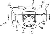
图1是根据本发明的一个实施例的刺血装置和端罩的透视图。Figure 1 is a perspective view of a lancing device and end shield according to one embodiment of the present invention.
图2是图1的刺血装置的前视图。Figure 2 is a front view of the lancing device of Figure 1 .
图3是图1的刺血装置的前视图,而刺血针容纳在其内。Figure 3 is a front view of the lancing device of Figure 1 with the lancet received therein.
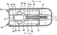
图4是图1的刺血装置的截面图,而刺血针容纳在其内,刺血装置在静止位置内。4 is a cross-sectional view of the lancing device of FIG. 1 with the lancet received therein and the lancing device in a rest position.
图5是在扳起位置内的图1的刺血装置的截面图。5 is a cross-sectional view of the lancing device of FIG. 1 in a cocked position.
图6是在扳起好的位置内的图1的刺血装置的截面图。Figure 6 is a cross-sectional view of the lancing device of Figure 1 in the cocked position.
图7是在刺透位置内的图1的刺血装置的截面图。Figure 7 is a cross-sectional view of the lancing device of Figure 1 in the lancing position.
图8是根据本发明的一个实施例的图1的刺血装置的按钮的前视图。8 is a front view of a button of the lancing device of FIG. 1 according to one embodiment of the present invention.
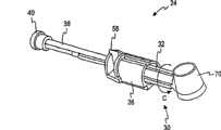
图9是根据本发明的一个实施例的包含在图1的刺血装置内的刺血机构的透视图。9 is a perspective view of a lancing mechanism included in the lancing device of FIG. 1 in accordance with one embodiment of the present invention.
尽管本发明可以进行多种更改并且可以采用多种可选择的形式,但在这里,通过在附图中的例子,显示了特定的实施例,并且详细地描述了特定的实施例。然而,应该理解的是,本发明不是旨在受到所披露的特别形式的限制。相反地,本发明涵盖了在如附加的权利要求书所限定的本发明的主旨和范围内的所有更改、等价物和替代物。While the invention is capable of many modifications and alternative forms, herein, by way of example in the drawings, specific embodiments are shown and described in detail. It should be understood, however, that the invention is not intended to be limited to the particular forms disclosed. On the contrary, the invention covers all modifications, equivalents and alternatives falling within the spirit and scope of the invention as defined by the appended claims.
具体实施方式Detailed ways
本发明涉及适合于容纳刺血针用于从检验对象抽取体液的刺血装置。体液大体上包含至少一种分析物,分析物然后可以被检定,以测定其在体液样本内的浓度。The present invention relates to a lancing device adapted to receive a lancet for withdrawing bodily fluid from a test subject. The body fluid generally contains at least one analyte, which can then be assayed to determine its concentration within the body fluid sample.
刺血装置和刺血针可以用于从检验对象产生血液样本或体液样本。这个样本然后用仪表和检验条或类似的装置进行分析,以测定所要检定的分析物的浓度。可以用刺血装置进行收集的分析物的类型的例子包括葡萄糖、脂质类(例如胆固醇、甘油三酸酯、LDL或HDL)、微白蛋白、血红蛋白A1C、果糖、乳酸盐或胆红素。Lancing devices and lancets may be used to produce a sample of blood or bodily fluid from a test subject. This sample is then analyzed using a meter and test strip or similar device to determine the concentration of the analyte to be assayed. Examples of the types of analytes that can be collected with a lancing device include glucose, lipids (such as cholesterol, triglycerides, LDL, or HDL), microalbumin, hemoglobin A1C, fructose, lactate, or bilirubin .
现在翻到附图,并且首先翻到图1-3,图示了根据本发明的一个实施例的用于从检验对象得到流体样本的刺血装置10。刺血装置10具有主壳12,可移动的壳14是可相对于主壳12进行移动的。主壳12包括第一主壳部分12a和第二主壳部分12b。第一主壳部分12a和第二主壳部分12b可以是可移开地可连接的,或可以形成为或模制为一个永久连接的物件。在刺血装置10的检验端上,端罩支撑件16连接到主壳12。端罩18可以可移开地连接到端罩支撑件16。当连接的时候,例如通过一对与端罩支撑件16整合形成在一起的支撑臂20a-b,端罩18保持在端罩支撑件16上。Turning now to the drawings, and first to FIGS. 1-3 , there is illustrated a
当使用的时候,可移动的壳14受到拉动而远离主壳12,以使内部刺血机构移动到扳起好的位置,然后下压按钮22,以激励刺血机构24(图9),从而使刺血针30的针尖34的锐利尖端被推过形成在端罩18内的孔(未显示)。刺血装置10可以配备许多不同的端罩18,每个端罩18具有不同的宽度,以有助于以多种深度刺透皮肤。可选择地,端罩18可以包括可调整的调节控制盘26,以通过使用单一的端罩18而允许以不同的深度进行刺透。When in use, the
图2-3图示了移开了端罩18的刺血装置10。刺血针固定件36包括形成在其内的位于中心的大体上为圆柱形的孔28。如图3所示,孔28适合于容纳刺血针30。刺血针30包括刺血针主体32,而带有锐利尖端的针尖34从针主体延伸。针尖34可以包封在保护罩70(图9)内,以使使用者免于发生意外刺透。另外,保护罩70有助于防止针尖34在使用之前受到污染,并且也可以在使用针尖34之后在废弃刺血针30之前进行替换。2-3 illustrate lancing
也参考图4,图示了在静止位置内的分离了端罩18的刺血装置10的截面图。通过与其整合形成在一起,刺血针固定件36连接到延长杆38。杆38具有支撑在可移动的壳14内的保持件40。驱动弹簧42围绕杆38布置在刺血针固定件36和与第一主壳部分12a整合形成在一起的弹簧停止件44之间。Referring also to FIG. 4 , there is illustrated a cross-sectional view of the lancing
可移动的壳14具有一对与其整合形成在一起的延长的柱48a、b。柱48a、b中的每个都经过形成在第一主壳部分12a内的孔(未显示)延伸到主壳12内。在可移动的壳14内,第二弹簧46围绕杆38布置。第二弹簧46的第一端布置靠在可移动的壳14的内部表面上,而第二弹簧46的第二端布置靠在杆38的保持件46上。第二弹簧46沿着刺血装置10的纵向轴线在中心位于可移动的壳14内。The
图4图示了当刺血装置10没有使用的时候的刺血装置10的内部。在这个位置内,刺血针固定件36布置在位于刺透位置和扳起好的位置之间的静止位置内。在静止位置内,驱动弹簧42和第二弹簧46都大致上解除压缩,并且彼此处于平衡。图5图示了当刺血针固定件36和可移动的壳14在扳起位置内的时候的刺血装置10的内部(刺血针30未显示),在这个位置内,可移动的壳14受到拉动而远离主壳12。在扳起位置内,当使用者移动可移动的壳14在箭头A的方向上远离壳12的时候,驱动弹簧42和第二弹簧46都大致上受到压缩。Figure 4 illustrates the interior of the lancing
现在参考图4-6和图8,为了使刺血针固定件36从其静止位置移动到其扳起位置,可移动的壳14受到拉动而在箭头A的方向上远离主壳12。可移动的壳14继续受到拉动—对抗驱动弹簧42和第二弹簧46的力—直到多个形成在刺血针固定件36上的成角度的停止部件50a、b移动经过(如图4-6所示向右)多个位于按钮22上的抓持臂52a、b(如图8最佳所示)。抓持臂52a、b中的每个具有适合于接合成角度的停止部件50a、b的各自的端部53a、b。抓持臂52a、b的端部53a、b相反于成角度的停止部件50a、b成角度,从而当成角度的停止部件50a、b在箭头A的方向上进行移动的时候,它们接触抓持臂52a、b的端部53a、b。成角度的停止部件50a、b的移动在第一主壳部分12a的方向上推动抓持臂52a、b的端部53a、b及所连接的按钮22。Referring now to FIGS. 4-6 and 8 , to move the
一旦成角度的停止部件50a、b移动经过抓持臂52a、b的端部53a、b,位于第二主壳部分12b和按钮22之间的弹簧机构64(图8)推动抓持臂52a、b朝向第一主壳部分12a。这个移动使抓持臂52a、b的端部53a、b接合成角度的停止部件50a、b。在这个位置内,防止由于驱动弹簧42而引起的刺血针固定件36在箭头B的方向上的移动。如图6所示,在接合了成角度的停止部件50a、b之后,使用者释放可移动的壳14,并且允许现在受到压缩的第二弹簧46推动可移动的壳14回到其邻近主壳12的初始位置。刺血装置10现在在其扳起好的位置内,在其中,驱动弹簧42大致上受到压缩,同时第二弹簧46大致上解除压缩。Once the
通过形成在刺血针固定件36的部分上的引导肋56(图9),刺血针固定件36在其静止位置和扳起好的位置之间受到引导。引导肋56行进在形成在一对凸起的引导轨道60a、b之间的槽58内,引导轨道60a、b形成在第一主壳12a的内部部分内。The
为了在检验对象的皮肤上形成刺孔,端罩18连接到刺血装置10。当端罩18连接的时候,刺血针固定件36可以在扳起好的位置内,或一旦当端罩18可移开地连接到端罩支撑件16的时候,刺血针固定件36就可以扳起。端罩18然后牢固地放置靠在进行刺透的皮肤上,并且下压按钮22。下压按钮22使与按钮22的底部整合形成在一起的抓持臂52a、b(图8)朝向第一主壳部分12a进行移动而远离刺血针固定件36。因而,不再通过抓持臂52a、b的端部53a、b与刺血针固定件36的成角度的停止部件50a、b接触而防止刺血针固定件36在箭头B的方向上进行移动。弹簧机构64(图8)—例如可发生弹性变形的泡沫材料—布置在按钮22和主壳12的部分之间,以使按钮22偏置到其非激励的位置。The
当如上所述释放刺血针固定件36时,驱动弹簧42在箭头B的方向上推动刺血针固定件36,直到针尖34的锐利尖(图3)经过在端罩18内的孔24,以进行刺透。当刺血针固定件36在箭头B的方向上进行移动的时候,所连接的杆38也在箭头B的方向上进行移动。当刺血针固定件36移动到刺透位置的时候,杆38的保持件40使第二弹簧46进行压缩。最后,受到压缩的第二弹簧46的返回力变得比驱动弹簧42的刺透力大。在此时,第二弹簧46的返回力使刺血针固定件36改变方向并且通过在箭头A的方向上进行移动而返回到其静止位置。可选择地,在一些实施例中,所提供的停止部件使刺血针固定件36停止而不会在箭头B的方向上移动得太远,此时第二弹簧46使刺血针固定件36返回到其静止位置。When the
然而,刺血针固定件36典型地在箭头A的方向上移动得比返回到其静止位置所需要的远。因而,轻微地对驱动弹簧42进行重新压缩,这使刺血针固定件36再次行进在箭头B的方向上。当刺血针固定件36开始在箭头B的方向上移动回来(由于轻微地对驱动弹簧42进行重新压缩)的时候,第二弹簧重新压缩。重新压缩第二弹簧46所需的力有效地对刺血针固定件36的移动进行阻尼。这样的阻尼有助于抑制或防止驱动弹簧42引起对皮肤进行第二次不想要的刺透-并且抑制或防止其本来的发生振动的趋势(由于它是可发生弹性变形的)。However,
现在翻到图8,图示了根据本发明的一个实施例的按钮22。按钮22包括主体62,两个抓持臂52a、b从主体62延伸。抓持臂52a、b中的每个分别包括相反于主体62的端部53a、b。每个端部53a、b适合于接合刺血针固定件36的成角度的停止部件50a、b。弹簧机构64例如可发生弹性变形的泡沫位于主体62的下侧上。如以上就图4-6所讨论的那样,当按钮22合并到刺血装置10内的时候,弹簧机构64接触第二主壳部分12b的部分,以使按钮22偏置在非激励位置内。Turning now to Figure 8, a
现在翻到图9,图示了布置在刺血针固定件36内的刺血针30的透视图。所显示的刺血针30带有具有与刺血针主体32整合形成在一起的部分并且覆盖了针尖34的锐利尖的保护罩70。在使用刺血装置10之前,新的刺血针30的刺血针主体32插入到布置在刺血针固定件36内的圆柱形的孔内,然后在图9所示的箭头C的方向上,将保护罩70从刺血针组件30拧下来。Turning now to FIG. 9 , a perspective view of
刺血针固定件36包括适合于插入到槽58(图5-6)内的引导肋56。引导肋56和槽58适合于有助于通过刺血针30对检验对象的皮肤进行线性的刺透。线性的刺孔是优选的,因为对于刺破皮肤,它们具有产生较小疼痛并且使复原加快的趋势。
上述刺血装置10的结构提供了许多先前通过典型的刺血装置没有认识的优点。例如,第二弹簧46既用于使可移动的壳14从扳起位置移动到静置位置,也用于使刺血针固定件36从其刺透位置返回到其静置位置。因而,通过只使用两个弹簧,刺血装置10是全功能的。The structure of the lancing
使用两个相反的弹簧,这允许只通过对在驱动弹簧42和第二弹簧46之间的弹簧比值进行调整而对刺透强度进行调整,这减小了对计算装置的多种构件的摩擦相互作用和质量的需要。典型地,驱动弹簧42的弹簧常数大于第二弹簧46的弹簧常数,这使第二弹簧46由于由驱动弹簧42提供的力而初始受到压缩。Using two opposing springs, this allows the penetration strength to be adjusted only by adjusting the spring ratio between the
上述刺血装置10的结构也允许驱动弹簧42和第二弹簧46都自由地浮置在杆38上。因而,不再需要连接每个弹簧的一端或两端,这减小了制造刺血装置10所需要的成本和时间。The construction of the lancing
尽管就一个或多个特别的实施例对本发明进行了描述,但本领域的那些技术人员应该认识到的是,在不偏离本发明的主旨和范围的情况下,可以对其进行许多改变。这些实施例和其明显的变体中的每个都被认为在本发明的主旨和范围内,这在接下来的权利要求书中进行了阐述。While the invention has been described in terms of one or more particular embodiments, those skilled in the art will recognize that many changes may be made without departing from the spirit and scope of the invention. Each of these embodiments and obvious variations thereof are considered to be within the spirit and scope of the present invention, which is set forth in the following claims.
Claims (6)
Applications Claiming Priority (2)
| Application Number | Priority Date | Filing Date | Title |
|---|---|---|---|
| US54277904P | 2004-02-06 | 2004-02-06 | |
| US60/542779 | 2004-02-06 |
Publications (2)
| Publication Number | Publication Date |
|---|---|
| CN1917809A CN1917809A (en) | 2007-02-21 |
| CN100508888Ctrue CN100508888C (en) | 2009-07-08 |
Family
ID=34860339
Family Applications (1)
| Application Number | Title | Priority Date | Filing Date |
|---|---|---|---|
| CNB2005800041439AExpired - Fee RelatedCN100508888C (en) | 2004-02-06 | 2005-02-04 | Dampening and retraction mechanism for a lancing device |
Country Status (18)
| Country | Link |
|---|---|
| US (1) | US20080039885A1 (en) |
| EP (2) | EP2011439A1 (en) |
| JP (1) | JP2007521122A (en) |
| KR (1) | KR20060134055A (en) |
| CN (1) | CN100508888C (en) |
| AT (1) | ATE415127T1 (en) |
| AU (1) | AU2005212297A1 (en) |
| BR (1) | BRPI0507324A (en) |
| CA (1) | CA2553624A1 (en) |
| CR (1) | CR8598A (en) |
| DE (1) | DE602005011251D1 (en) |
| ES (1) | ES2315844T3 (en) |
| MA (1) | MA28351A1 (en) |
| NO (1) | NO20063975L (en) |
| PL (1) | PL1713391T3 (en) |
| PT (1) | PT1713391E (en) |
| RU (1) | RU2006132065A (en) |
| WO (1) | WO2005077275A1 (en) |
Families Citing this family (85)
| Publication number | Priority date | Publication date | Assignee | Title |
|---|---|---|---|---|
| US6391005B1 (en) | 1998-03-30 | 2002-05-21 | Agilent Technologies, Inc. | Apparatus and method for penetration with shaft having a sensor for sensing penetration depth |
| US7175641B1 (en) | 1998-06-11 | 2007-02-13 | Stat Medical Devices, Inc. | Lancet having adjustable penetration depth |
| US8641644B2 (en) | 2000-11-21 | 2014-02-04 | Sanofi-Aventis Deutschland Gmbh | Blood testing apparatus having a rotatable cartridge with multiple lancing elements and testing means |
| US9427532B2 (en) | 2001-06-12 | 2016-08-30 | Sanofi-Aventis Deutschland Gmbh | Tissue penetration device |
| US9226699B2 (en) | 2002-04-19 | 2016-01-05 | Sanofi-Aventis Deutschland Gmbh | Body fluid sampling module with a continuous compression tissue interface surface |
| EP1395185B1 (en) | 2001-06-12 | 2010-10-27 | Pelikan Technologies Inc. | Electric lancet actuator |
| US7344507B2 (en) | 2002-04-19 | 2008-03-18 | Pelikan Technologies, Inc. | Method and apparatus for lancet actuation |
| JP4209767B2 (en) | 2001-06-12 | 2009-01-14 | ペリカン テクノロジーズ インコーポレイテッド | Self-optimized cutting instrument with adaptive means for temporary changes in skin properties |
| US7041068B2 (en) | 2001-06-12 | 2006-05-09 | Pelikan Technologies, Inc. | Sampling module device and method |
| US7981056B2 (en) | 2002-04-19 | 2011-07-19 | Pelikan Technologies, Inc. | Methods and apparatus for lancet actuation |
| US7749174B2 (en) | 2001-06-12 | 2010-07-06 | Pelikan Technologies, Inc. | Method and apparatus for lancet launching device intergrated onto a blood-sampling cartridge |
| US9795747B2 (en) | 2010-06-02 | 2017-10-24 | Sanofi-Aventis Deutschland Gmbh | Methods and apparatus for lancet actuation |
| US8337419B2 (en) | 2002-04-19 | 2012-12-25 | Sanofi-Aventis Deutschland Gmbh | Tissue penetration device |
| US9795334B2 (en) | 2002-04-19 | 2017-10-24 | Sanofi-Aventis Deutschland Gmbh | Method and apparatus for penetrating tissue |
| US7892183B2 (en) | 2002-04-19 | 2011-02-22 | Pelikan Technologies, Inc. | Method and apparatus for body fluid sampling and analyte sensing |
| US7297122B2 (en) | 2002-04-19 | 2007-11-20 | Pelikan Technologies, Inc. | Method and apparatus for penetrating tissue |
| US8360992B2 (en) | 2002-04-19 | 2013-01-29 | Sanofi-Aventis Deutschland Gmbh | Method and apparatus for penetrating tissue |
| US7674232B2 (en) | 2002-04-19 | 2010-03-09 | Pelikan Technologies, Inc. | Method and apparatus for penetrating tissue |
| US7491178B2 (en) | 2002-04-19 | 2009-02-17 | Pelikan Technologies, Inc. | Method and apparatus for penetrating tissue |
| US7901362B2 (en) | 2002-04-19 | 2011-03-08 | Pelikan Technologies, Inc. | Method and apparatus for penetrating tissue |
| US7229458B2 (en) | 2002-04-19 | 2007-06-12 | Pelikan Technologies, Inc. | Method and apparatus for penetrating tissue |
| US8267870B2 (en) | 2002-04-19 | 2012-09-18 | Sanofi-Aventis Deutschland Gmbh | Method and apparatus for body fluid sampling with hybrid actuation |
| US8372016B2 (en) | 2002-04-19 | 2013-02-12 | Sanofi-Aventis Deutschland Gmbh | Method and apparatus for body fluid sampling and analyte sensing |
| US9314194B2 (en) | 2002-04-19 | 2016-04-19 | Sanofi-Aventis Deutschland Gmbh | Tissue penetration device |
| US8579831B2 (en) | 2002-04-19 | 2013-11-12 | Sanofi-Aventis Deutschland Gmbh | Method and apparatus for penetrating tissue |
| US8784335B2 (en) | 2002-04-19 | 2014-07-22 | Sanofi-Aventis Deutschland Gmbh | Body fluid sampling device with a capacitive sensor |
| US7976476B2 (en) | 2002-04-19 | 2011-07-12 | Pelikan Technologies, Inc. | Device and method for variable speed lancet |
| US7708701B2 (en) | 2002-04-19 | 2010-05-04 | Pelikan Technologies, Inc. | Method and apparatus for a multi-use body fluid sampling device |
| US7547287B2 (en) | 2002-04-19 | 2009-06-16 | Pelikan Technologies, Inc. | Method and apparatus for penetrating tissue |
| US9248267B2 (en) | 2002-04-19 | 2016-02-02 | Sanofi-Aventis Deustchland Gmbh | Tissue penetration device |
| US7232451B2 (en) | 2002-04-19 | 2007-06-19 | Pelikan Technologies, Inc. | Method and apparatus for penetrating tissue |
| US7909778B2 (en) | 2002-04-19 | 2011-03-22 | Pelikan Technologies, Inc. | Method and apparatus for penetrating tissue |
| US7331931B2 (en) | 2002-04-19 | 2008-02-19 | Pelikan Technologies, Inc. | Method and apparatus for penetrating tissue |
| US8221334B2 (en) | 2002-04-19 | 2012-07-17 | Sanofi-Aventis Deutschland Gmbh | Method and apparatus for penetrating tissue |
| US8702624B2 (en) | 2006-09-29 | 2014-04-22 | Sanofi-Aventis Deutschland Gmbh | Analyte measurement device with a single shot actuator |
| US8574895B2 (en) | 2002-12-30 | 2013-11-05 | Sanofi-Aventis Deutschland Gmbh | Method and apparatus using optical techniques to measure analyte levels |
| DE602004028463D1 (en) | 2003-05-30 | 2010-09-16 | Pelikan Technologies Inc | METHOD AND DEVICE FOR INJECTING LIQUID |
| US7850621B2 (en) | 2003-06-06 | 2010-12-14 | Pelikan Technologies, Inc. | Method and apparatus for body fluid sampling and analyte sensing |
| WO2006001797A1 (en) | 2004-06-14 | 2006-01-05 | Pelikan Technologies, Inc. | Low pain penetrating |
| US7905898B2 (en)* | 2003-08-15 | 2011-03-15 | Stat Medical Devices, Inc. | Adjustable lancet device and method |
| US8282576B2 (en) | 2003-09-29 | 2012-10-09 | Sanofi-Aventis Deutschland Gmbh | Method and apparatus for an improved sample capture device |
| EP1680014A4 (en) | 2003-10-14 | 2009-01-21 | Pelikan Technologies Inc | METHOD AND DEVICE FOR A VARIABLE USER INTERFACE |
| US8668656B2 (en) | 2003-12-31 | 2014-03-11 | Sanofi-Aventis Deutschland Gmbh | Method and apparatus for improving fluidic flow and sample capture |
| US7822454B1 (en) | 2005-01-03 | 2010-10-26 | Pelikan Technologies, Inc. | Fluid sampling device with improved analyte detecting member configuration |
| WO2006011062A2 (en) | 2004-05-20 | 2006-02-02 | Albatros Technologies Gmbh & Co. Kg | Printable hydrogel for biosensors |
| WO2005120365A1 (en) | 2004-06-03 | 2005-12-22 | Pelikan Technologies, Inc. | Method and apparatus for a fluid sampling device |
| US9775553B2 (en) | 2004-06-03 | 2017-10-03 | Sanofi-Aventis Deutschland Gmbh | Method and apparatus for a fluid sampling device |
| US8652831B2 (en)* | 2004-12-30 | 2014-02-18 | Sanofi-Aventis Deutschland Gmbh | Method and apparatus for analyte measurement test time |
| US20090054811A1 (en)* | 2004-12-30 | 2009-02-26 | Dirk Boecker | Method and apparatus for analyte measurement test time |
| US9289161B2 (en) | 2005-01-28 | 2016-03-22 | Stat Medical Divices, Inc. | Multi-lancet unit, method and lancet device using the multi-lancet unit, and method of assembling and/or making the multi-lancet unit |
| CN101163446A (en) | 2005-03-04 | 2008-04-16 | 拜尔保健有限公司 | Lancet-release mechanism |
| US8784444B2 (en) | 2005-03-04 | 2014-07-22 | Bayer Healthcare Llc | Lancet release mechanism |
| EP1903927A2 (en)* | 2005-06-30 | 2008-04-02 | Bayer Healthcare, LLC | Single-puncture lancing system |
| WO2007005665A1 (en) | 2005-06-30 | 2007-01-11 | Bayer Healthcare Llc | Single-puncture lancing system |
| US8048098B2 (en) | 2005-07-14 | 2011-11-01 | Bayer Healthcare Llc | Lancing device for one skin puncture |
| US8617195B2 (en) | 2005-08-04 | 2013-12-31 | Bayer Healthcare Llc | Lancing device |
| US7704265B2 (en) | 2005-11-03 | 2010-04-27 | Stat Medical Devices, Inc. | Disposable/single-use blade lancet device and method |
| US20070173876A1 (en)* | 2006-01-20 | 2007-07-26 | Lifescan, Inc. | Lancing device with dampened spring |
| EP1992285A4 (en)* | 2006-03-08 | 2011-12-28 | Arkray Inc | Lancet device |
| US8469986B2 (en) | 2007-03-30 | 2013-06-25 | Stat Medical Devices, Inc. | Lancet device with combined trigger and cocking mechanism and method |
| WO2008157610A1 (en) | 2007-06-19 | 2008-12-24 | Stat Medical Devices, Inc. | Lancet device with depth adjustment and lancet removal system and method |
| USD612279S1 (en) | 2008-01-18 | 2010-03-23 | Lifescan Scotland Limited | User interface in an analyte meter |
| EP2265324B1 (en) | 2008-04-11 | 2015-01-28 | Sanofi-Aventis Deutschland GmbH | Integrated analyte measurement system |
| US8932314B2 (en)* | 2008-05-09 | 2015-01-13 | Lifescan Scotland Limited | Prime and fire lancing device with contacting bias drive and method |
| USD586465S1 (en) | 2008-05-09 | 2009-02-10 | Lifescan Scotland Limited | Handheld lancing device |
| US8454533B2 (en) | 2008-05-09 | 2013-06-04 | Lifescan Scotland Limited | Lancing devices and methods |
| US20090281457A1 (en)* | 2008-05-09 | 2009-11-12 | Lifescan Soctland Ltd. | Prime and fire lancing device with non-contacting bias drive and method |
| USD586916S1 (en) | 2008-05-09 | 2009-02-17 | Lifescan Scotland, Ltd. | Handheld lancing device |
| US8828038B2 (en) | 2008-06-05 | 2014-09-09 | Bayer Healthcare Llc | Lancing device |
| WO2009148431A1 (en)* | 2008-06-05 | 2009-12-10 | Bayer Healthcare Llc | Lancing device |
| DE102008039111B4 (en) | 2008-06-06 | 2012-01-12 | Gerresheimer Regensburg Gmbh | Lancing device for a blood sampling and method for taking a blood sample |
| DE102008037082B4 (en)* | 2008-06-06 | 2012-05-24 | Gerresheimer Regensburg Gmbh | Lancing device for a blood sampling |
| USD611372S1 (en) | 2008-09-19 | 2010-03-09 | Lifescan Scotland Limited | Analyte test meter |
| US8944990B2 (en) | 2008-10-27 | 2015-02-03 | Ams Research Corporation | Surgical needle and anchor system with retractable features |
| USD775729S1 (en)* | 2008-10-27 | 2017-01-03 | Astora Women's Health, Llc | Surgical needle device |
| US9375169B2 (en) | 2009-01-30 | 2016-06-28 | Sanofi-Aventis Deutschland Gmbh | Cam drive for managing disposable penetrating member actions with a single motor and motor and control system |
| DE102009025443B4 (en)* | 2009-04-03 | 2012-06-06 | Gerresheimer Regensburg Gmbh | Blood lancet device with puncture depth adjustment |
| USD611602S1 (en)* | 2009-05-11 | 2010-03-09 | Facet Technologies, Llc | Lancing device |
| USD634426S1 (en) | 2010-04-08 | 2011-03-15 | Facet Technologies, Llc | Lancing device |
| US8965476B2 (en) | 2010-04-16 | 2015-02-24 | Sanofi-Aventis Deutschland Gmbh | Tissue penetration device |
| USD745675S1 (en)* | 2011-11-08 | 2015-12-15 | “HTL-STREFA” Spolka Akcyjna | Device for puncturing the patient's skin |
| RU2531471C1 (en)* | 2013-07-04 | 2014-10-20 | федеральное государственное бюджетное учреждение "Межотраслевой научно-технический комплекс "Микрохирургия глаза" имени академика С.Н. Федорова" Министерства здравоохранения Российской Федерации | Instrument for graduated scarification of corneal epithelium |
| US10070811B2 (en) | 2014-06-26 | 2018-09-11 | Stat Medical Devices, Inc. | Lancing device with depth adjustment and lancet removal system and method |
| USD794790S1 (en)* | 2014-08-29 | 2017-08-15 | Sterilance Medical (Suzhou) Inc. | Disposable safety lancet |
| CA189341S (en)* | 2018-10-29 | 2020-11-23 | Mir Srl Medical International Res | Hand operated medical instrument |
Citations (1)
| Publication number | Priority date | Publication date | Assignee | Title |
|---|---|---|---|---|
| US4517978A (en)* | 1983-01-13 | 1985-05-21 | Levin Paul D | Blood sampling instrument |
Family Cites Families (11)
| Publication number | Priority date | Publication date | Assignee | Title |
|---|---|---|---|---|
| US4535769A (en)* | 1981-03-23 | 1985-08-20 | Becton, Dickinson And Company | Automatic retractable lancet assembly |
| US5797942A (en)* | 1996-09-23 | 1998-08-25 | Schraga; Steven | Re-usable end cap for re-usable lancet devices for removing and disposing of a contaminated lancet |
| US6027459A (en)* | 1996-12-06 | 2000-02-22 | Abbott Laboratories | Method and apparatus for obtaining blood for diagnostic tests |
| US5954738A (en)* | 1997-07-31 | 1999-09-21 | Bayer Corporation | Blood sampling device with lancet damping system |
| US6706000B2 (en)* | 1997-11-21 | 2004-03-16 | Amira Medical | Methods and apparatus for expressing body fluid from an incision |
| US6168606B1 (en)* | 1999-11-10 | 2001-01-02 | Palco Labs, Inc. | Single-use lancet device |
| US6558402B1 (en)* | 1999-08-03 | 2003-05-06 | Becton, Dickinson And Company | Lancer |
| US6283982B1 (en)* | 1999-10-19 | 2001-09-04 | Facet Technologies, Inc. | Lancing device and method of sample collection |
| CA2461370A1 (en)* | 2001-09-26 | 2003-05-15 | F. Hoffmann-La Roche Ag | Method and apparatus for sampling bodily fluid |
| DE10222235A1 (en)* | 2002-05-16 | 2003-11-27 | Roche Diagnostics Gmbh | Blood Collection system |
| US7303573B2 (en)* | 2003-05-29 | 2007-12-04 | Abbott Laboratories | Lancet device |
- 2005
- 2005-02-04JPJP2006552279Apatent/JP2007521122A/ennot_activeWithdrawn
- 2005-02-04EPEP08018281Apatent/EP2011439A1/ennot_activeWithdrawn
- 2005-02-04DEDE602005011251Tpatent/DE602005011251D1/ennot_activeExpired - Lifetime
- 2005-02-04CACA002553624Apatent/CA2553624A1/ennot_activeAbandoned
- 2005-02-04PLPL05712899Tpatent/PL1713391T3/enunknown
- 2005-02-04KRKR1020067015913Apatent/KR20060134055A/ennot_activeWithdrawn
- 2005-02-04WOPCT/US2005/003623patent/WO2005077275A1/enactiveApplication Filing
- 2005-02-04PTPT05712899Tpatent/PT1713391E/enunknown
- 2005-02-04EPEP05712899Apatent/EP1713391B1/ennot_activeExpired - Lifetime
- 2005-02-04ATAT05712899Tpatent/ATE415127T1/ennot_activeIP Right Cessation
- 2005-02-04RURU2006132065/14Apatent/RU2006132065A/ennot_activeApplication Discontinuation
- 2005-02-04USUS10/590,533patent/US20080039885A1/ennot_activeAbandoned
- 2005-02-04ESES05712899Tpatent/ES2315844T3/ennot_activeExpired - Lifetime
- 2005-02-04AUAU2005212297Apatent/AU2005212297A1/ennot_activeAbandoned
- 2005-02-04BRBRPI0507324-3Apatent/BRPI0507324A/ennot_activeIP Right Cessation
- 2005-02-04CNCNB2005800041439Apatent/CN100508888C/ennot_activeExpired - Fee Related
- 2006
- 2006-08-07MAMA29247Apatent/MA28351A1/enunknown
- 2006-09-05NONO20063975Apatent/NO20063975L/ennot_activeApplication Discontinuation
- 2006-09-06CRCR8598Apatent/CR8598A/ennot_activeApplication Discontinuation
Patent Citations (1)
| Publication number | Priority date | Publication date | Assignee | Title |
|---|---|---|---|---|
| US4517978A (en)* | 1983-01-13 | 1985-05-21 | Levin Paul D | Blood sampling instrument |
Also Published As
| Publication number | Publication date |
|---|---|
| CA2553624A1 (en) | 2005-08-25 |
| DE602005011251D1 (en) | 2009-01-08 |
| EP1713391B1 (en) | 2008-11-26 |
| PT1713391E (en) | 2009-01-23 |
| US20080039885A1 (en) | 2008-02-14 |
| AU2005212297A1 (en) | 2005-08-25 |
| EP2011439A1 (en) | 2009-01-07 |
| EP1713391A1 (en) | 2006-10-25 |
| KR20060134055A (en) | 2006-12-27 |
| NO20063975L (en) | 2006-09-05 |
| PL1713391T3 (en) | 2009-05-29 |
| WO2005077275A1 (en) | 2005-08-25 |
| BRPI0507324A (en) | 2007-07-03 |
| JP2007521122A (en) | 2007-08-02 |
| CN1917809A (en) | 2007-02-21 |
| RU2006132065A (en) | 2008-03-20 |
| CR8598A (en) | 2007-02-07 |
| MA28351A1 (en) | 2006-12-01 |
| ES2315844T3 (en) | 2009-04-01 |
| ATE415127T1 (en) | 2008-12-15 |
Similar Documents
| Publication | Publication Date | Title |
|---|---|---|
| CN100508888C (en) | Dampening and retraction mechanism for a lancing device | |
| US8303615B2 (en) | Lancet-eject mechanism | |
| US5871494A (en) | Reproducible lancing for sampling blood | |
| US8864783B2 (en) | Lancing device | |
| US6183489B1 (en) | Disposable element for use in a body fluid sampling device | |
| US20080167673A1 (en) | Lancet Release Mechanism | |
| US9055898B2 (en) | Lancet release mechanism | |
| US20090131966A1 (en) | Single-puncture lancing system | |
| CN102309343B (en) | Micropore forming apparatus and micropore forming method | |
| US8940006B2 (en) | Single-puncture lancing system | |
| US8333782B2 (en) | Lancing device for one skin puncture | |
| KR20200016070A (en) | Pain-free blood collection device | |
| HK1104203A (en) | Dampening and retraction mechanism for a lancing device | |
| MXPA06008844A (en) | Dampening and retraction mechanism for a lancing device | |
| GB2373731A (en) | Apparatus and method for sampling blood |
Legal Events
| Date | Code | Title | Description |
|---|---|---|---|
| C06 | Publication | ||
| PB01 | Publication | ||
| C10 | Entry into substantive examination | ||
| SE01 | Entry into force of request for substantive examination | ||
| REG | Reference to a national code | Ref country code:HK Ref legal event code:DE Ref document number:1104203 Country of ref document:HK | |
| C14 | Grant of patent or utility model | ||
| GR01 | Patent grant | ||
| REG | Reference to a national code | Ref country code:HK Ref legal event code:WD Ref document number:1104203 Country of ref document:HK | |
| CF01 | Termination of patent right due to non-payment of annual fee | ||
| CF01 | Termination of patent right due to non-payment of annual fee | Granted publication date:20090708 |