CN100506588C - Work vehicle with transverse travel system - Google Patents
Work vehicle with transverse travel systemDownload PDFInfo
- Publication number
- CN100506588C CN100506588CCNB018127150ACN01812715ACN100506588CCN 100506588 CCN100506588 CCN 100506588CCN B018127150 ACNB018127150 ACN B018127150ACN 01812715 ACN01812715 ACN 01812715ACN 100506588 CCN100506588 CCN 100506588C
- Authority
- CN
- China
- Prior art keywords
- wheel
- pair
- wheels
- battery
- vehicle body
- Prior art date
- Legal status (The legal status is an assumption and is not a legal conclusion. Google has not performed a legal analysis and makes no representation as to the accuracy of the status listed.)
- Expired - Fee Related
Links
Images


Classifications
- B—PERFORMING OPERATIONS; TRANSPORTING
- B62—LAND VEHICLES FOR TRAVELLING OTHERWISE THAN ON RAILS
- B62D—MOTOR VEHICLES; TRAILERS
- B62D7/00—Steering linkage; Stub axles or their mountings
- B62D7/06—Steering linkage; Stub axles or their mountings for individually-pivoted wheels, e.g. on king-pins
- B62D7/14—Steering linkage; Stub axles or their mountings for individually-pivoted wheels, e.g. on king-pins the pivotal axes being situated in more than one plane transverse to the longitudinal centre line of the vehicle, e.g. all-wheel steering
- B—PERFORMING OPERATIONS; TRANSPORTING
- B60—VEHICLES IN GENERAL
- B60K—ARRANGEMENT OR MOUNTING OF PROPULSION UNITS OR OF TRANSMISSIONS IN VEHICLES; ARRANGEMENT OR MOUNTING OF PLURAL DIVERSE PRIME-MOVERS IN VEHICLES; AUXILIARY DRIVES FOR VEHICLES; INSTRUMENTATION OR DASHBOARDS FOR VEHICLES; ARRANGEMENTS IN CONNECTION WITH COOLING, AIR INTAKE, GAS EXHAUST OR FUEL SUPPLY OF PROPULSION UNITS IN VEHICLES
- B60K7/00—Disposition of motor in, or adjacent to, traction wheel
- B60K7/0007—Disposition of motor in, or adjacent to, traction wheel the motor being electric
- B—PERFORMING OPERATIONS; TRANSPORTING
- B60—VEHICLES IN GENERAL
- B60K—ARRANGEMENT OR MOUNTING OF PROPULSION UNITS OR OF TRANSMISSIONS IN VEHICLES; ARRANGEMENT OR MOUNTING OF PLURAL DIVERSE PRIME-MOVERS IN VEHICLES; AUXILIARY DRIVES FOR VEHICLES; INSTRUMENTATION OR DASHBOARDS FOR VEHICLES; ARRANGEMENTS IN CONNECTION WITH COOLING, AIR INTAKE, GAS EXHAUST OR FUEL SUPPLY OF PROPULSION UNITS IN VEHICLES
- B60K7/00—Disposition of motor in, or adjacent to, traction wheel
- B60K7/0015—Disposition of motor in, or adjacent to, traction wheel the motor being hydraulic
- B—PERFORMING OPERATIONS; TRANSPORTING
- B62—LAND VEHICLES FOR TRAVELLING OTHERWISE THAN ON RAILS
- B62D—MOTOR VEHICLES; TRAILERS
- B62D7/00—Steering linkage; Stub axles or their mountings
- B62D7/06—Steering linkage; Stub axles or their mountings for individually-pivoted wheels, e.g. on king-pins
- B62D7/14—Steering linkage; Stub axles or their mountings for individually-pivoted wheels, e.g. on king-pins the pivotal axes being situated in more than one plane transverse to the longitudinal centre line of the vehicle, e.g. all-wheel steering
- B62D7/15—Steering linkage; Stub axles or their mountings for individually-pivoted wheels, e.g. on king-pins the pivotal axes being situated in more than one plane transverse to the longitudinal centre line of the vehicle, e.g. all-wheel steering characterised by means varying the ratio between the steering angles of the steered wheels
- B62D7/1509—Steering linkage; Stub axles or their mountings for individually-pivoted wheels, e.g. on king-pins the pivotal axes being situated in more than one plane transverse to the longitudinal centre line of the vehicle, e.g. all-wheel steering characterised by means varying the ratio between the steering angles of the steered wheels with different steering modes, e.g. crab-steering, or steering specially adapted for reversing of the vehicle
- B—PERFORMING OPERATIONS; TRANSPORTING
- B66—HOISTING; LIFTING; HAULING
- B66F—HOISTING, LIFTING, HAULING OR PUSHING, NOT OTHERWISE PROVIDED FOR, e.g. DEVICES WHICH APPLY A LIFTING OR PUSHING FORCE DIRECTLY TO THE SURFACE OF A LOAD
- B66F9/00—Devices for lifting or lowering bulky or heavy goods for loading or unloading purposes
- B66F9/06—Devices for lifting or lowering bulky or heavy goods for loading or unloading purposes movable, with their loads, on wheels or the like, e.g. fork-lift trucks
- B66F9/075—Constructional features or details
- B66F9/07568—Steering arrangements
- B—PERFORMING OPERATIONS; TRANSPORTING
- B66—HOISTING; LIFTING; HAULING
- B66F—HOISTING, LIFTING, HAULING OR PUSHING, NOT OTHERWISE PROVIDED FOR, e.g. DEVICES WHICH APPLY A LIFTING OR PUSHING FORCE DIRECTLY TO THE SURFACE OF A LOAD
- B66F9/00—Devices for lifting or lowering bulky or heavy goods for loading or unloading purposes
- B66F9/06—Devices for lifting or lowering bulky or heavy goods for loading or unloading purposes movable, with their loads, on wheels or the like, e.g. fork-lift trucks
- B66F9/075—Constructional features or details
- B66F9/07572—Propulsion arrangements
- B—PERFORMING OPERATIONS; TRANSPORTING
- B60—VEHICLES IN GENERAL
- B60K—ARRANGEMENT OR MOUNTING OF PROPULSION UNITS OR OF TRANSMISSIONS IN VEHICLES; ARRANGEMENT OR MOUNTING OF PLURAL DIVERSE PRIME-MOVERS IN VEHICLES; AUXILIARY DRIVES FOR VEHICLES; INSTRUMENTATION OR DASHBOARDS FOR VEHICLES; ARRANGEMENTS IN CONNECTION WITH COOLING, AIR INTAKE, GAS EXHAUST OR FUEL SUPPLY OF PROPULSION UNITS IN VEHICLES
- B60K1/00—Arrangement or mounting of electrical propulsion units
- B60K1/04—Arrangement or mounting of electrical propulsion units of the electric storage means for propulsion
- B—PERFORMING OPERATIONS; TRANSPORTING
- B60—VEHICLES IN GENERAL
- B60K—ARRANGEMENT OR MOUNTING OF PROPULSION UNITS OR OF TRANSMISSIONS IN VEHICLES; ARRANGEMENT OR MOUNTING OF PLURAL DIVERSE PRIME-MOVERS IN VEHICLES; AUXILIARY DRIVES FOR VEHICLES; INSTRUMENTATION OR DASHBOARDS FOR VEHICLES; ARRANGEMENTS IN CONNECTION WITH COOLING, AIR INTAKE, GAS EXHAUST OR FUEL SUPPLY OF PROPULSION UNITS IN VEHICLES
- B60K17/00—Arrangement or mounting of transmissions in vehicles
- B60K17/04—Arrangement or mounting of transmissions in vehicles characterised by arrangement, location or kind of gearing
- B60K17/043—Transmission unit disposed in on near the vehicle wheel, or between the differential gear unit and the wheel
- B—PERFORMING OPERATIONS; TRANSPORTING
- B60—VEHICLES IN GENERAL
- B60K—ARRANGEMENT OR MOUNTING OF PROPULSION UNITS OR OF TRANSMISSIONS IN VEHICLES; ARRANGEMENT OR MOUNTING OF PLURAL DIVERSE PRIME-MOVERS IN VEHICLES; AUXILIARY DRIVES FOR VEHICLES; INSTRUMENTATION OR DASHBOARDS FOR VEHICLES; ARRANGEMENTS IN CONNECTION WITH COOLING, AIR INTAKE, GAS EXHAUST OR FUEL SUPPLY OF PROPULSION UNITS IN VEHICLES
- B60K7/00—Disposition of motor in, or adjacent to, traction wheel
- B60K2007/0046—Disposition of motor in, or adjacent to, traction wheel the motor moving together with the vehicle body, i.e. moving independently from the wheel axle
- B—PERFORMING OPERATIONS; TRANSPORTING
- B60—VEHICLES IN GENERAL
- B60K—ARRANGEMENT OR MOUNTING OF PROPULSION UNITS OR OF TRANSMISSIONS IN VEHICLES; ARRANGEMENT OR MOUNTING OF PLURAL DIVERSE PRIME-MOVERS IN VEHICLES; AUXILIARY DRIVES FOR VEHICLES; INSTRUMENTATION OR DASHBOARDS FOR VEHICLES; ARRANGEMENTS IN CONNECTION WITH COOLING, AIR INTAKE, GAS EXHAUST OR FUEL SUPPLY OF PROPULSION UNITS IN VEHICLES
- B60K7/00—Disposition of motor in, or adjacent to, traction wheel
- B60K2007/0069—Disposition of motor in, or adjacent to, traction wheel the motor axle being perpendicular to the wheel axle
- B60K2007/0084—Disposition of motor in, or adjacent to, traction wheel the motor axle being perpendicular to the wheel axle the motor axle being vertical
- B—PERFORMING OPERATIONS; TRANSPORTING
- B60—VEHICLES IN GENERAL
- B60K—ARRANGEMENT OR MOUNTING OF PROPULSION UNITS OR OF TRANSMISSIONS IN VEHICLES; ARRANGEMENT OR MOUNTING OF PLURAL DIVERSE PRIME-MOVERS IN VEHICLES; AUXILIARY DRIVES FOR VEHICLES; INSTRUMENTATION OR DASHBOARDS FOR VEHICLES; ARRANGEMENTS IN CONNECTION WITH COOLING, AIR INTAKE, GAS EXHAUST OR FUEL SUPPLY OF PROPULSION UNITS IN VEHICLES
- B60K7/00—Disposition of motor in, or adjacent to, traction wheel
- B60K2007/0092—Disposition of motor in, or adjacent to, traction wheel the motor axle being coaxial to the wheel axle
- B—PERFORMING OPERATIONS; TRANSPORTING
- B60—VEHICLES IN GENERAL
- B60L—PROPULSION OF ELECTRICALLY-PROPELLED VEHICLES; SUPPLYING ELECTRIC POWER FOR AUXILIARY EQUIPMENT OF ELECTRICALLY-PROPELLED VEHICLES; ELECTRODYNAMIC BRAKE SYSTEMS FOR VEHICLES IN GENERAL; MAGNETIC SUSPENSION OR LEVITATION FOR VEHICLES; MONITORING OPERATING VARIABLES OF ELECTRICALLY-PROPELLED VEHICLES; ELECTRIC SAFETY DEVICES FOR ELECTRICALLY-PROPELLED VEHICLES
- B60L2220/00—Electrical machine types; Structures or applications thereof
- B60L2220/40—Electrical machine applications
- B60L2220/46—Wheel motors, i.e. motor connected to only one wheel
- B—PERFORMING OPERATIONS; TRANSPORTING
- B60—VEHICLES IN GENERAL
- B60Y—INDEXING SCHEME RELATING TO ASPECTS CROSS-CUTTING VEHICLE TECHNOLOGY
- B60Y2200/00—Type of vehicle
- B60Y2200/10—Road Vehicles
- B60Y2200/15—Fork lift trucks, Industrial trucks
- B—PERFORMING OPERATIONS; TRANSPORTING
- B60—VEHICLES IN GENERAL
- B60Y—INDEXING SCHEME RELATING TO ASPECTS CROSS-CUTTING VEHICLE TECHNOLOGY
- B60Y2200/00—Type of vehicle
- B60Y2200/40—Special vehicles
- B60Y2200/41—Construction vehicles, e.g. graders, excavators
Landscapes
- Engineering & Computer Science (AREA)
- Transportation (AREA)
- Mechanical Engineering (AREA)
- Chemical & Material Sciences (AREA)
- Combustion & Propulsion (AREA)
- Structural Engineering (AREA)
- Life Sciences & Earth Sciences (AREA)
- Geology (AREA)
- Civil Engineering (AREA)
- Steering-Linkage Mechanisms And Four-Wheel Steering (AREA)
- Forklifts And Lifting Vehicles (AREA)
- Handcart (AREA)
- Arrangement Or Mounting Of Propulsion Units For Vehicles (AREA)
Abstract
Description
Translated fromChinese技术领域technical field
本发明涉及具有可切换成横向行走的横行系统的作业车辆。The present invention relates to a work vehicle having a traverse system switchable to traverse.
背景技术Background technique
在现有技术中,作为具有横行系统的车辆,见诸于大型搬运车、一部分装载机等,存在于叉车、伸缩式电气车辆。另外,还有对车辆运动横向安装有柱与叉的处理长物件的侧叉车。但是在配重式的叉车中,除通常的作业之外,并不存在可横行、与侧叉车具有同样的功能的。为了成就这样的叉车,必须把作为驱动轮的前车轮向正横向操纵。In the prior art, as a vehicle having a traverse system, there are large trucks, some loaders, etc., and there are forklifts and telescopic electric vehicles. In addition, there are side forklifts that handle long objects with columns and forks installed transversely to the movement of the vehicle. However, counterweight forklifts do not have the same functions as side forklifts, except for normal operations. In order to achieve such a forklift, it is necessary to steer the front wheels as the driving wheels to the positive side.
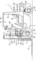
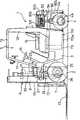
即,图15中所示出的现有叉车1,在其车身2的前部设有左右一对前车轮(驱动轮)3,并在后部设有左右一对后车轮(换向轮)4,在车身2的前部上方设驾驶室5。在所述车身2的前端部,通过车宽方向的连结轴7可在前后方向自由转动地安装着在上下方向可自由伸缩的柱6,同时,在车身2与柱6间设进行前后转动的倾倒用液压缸8。That is, the existing
所述柱6由叉车1一侧的左右一对外框9、和由该外框9导向自由升降的左右一对内框10构成,在外框9与内框10间设升降液压缸11。另外还设有由内框10侧导向自由升降的升降托架12,同时在该升降托架12上,通过上下一对伸缩杆设有左右一对叉13。The
在所述驾驶室5中,配设有驾驶座15和位于该驾驶座15前方的手柄16等;在上方通过从本体2一侧立设的前管17与后管18配设顶盖19。在驾驶座15后方于本体2上设配重20。In the cab 5, a driver's
但在上述现有叉车1中,由于左右前车轮3由共同的行走驱动装置驱动等,不能操纵这些前车轮3向着正横向,因而不能进行横向行走。But in above-mentioned existing
另外,由于左右前车轮3之间与左右后车轮4间存在车轴,必须避开这些车轴搭载电池,由于这种限制,不能很容易地进行这些电池的装拆、即不方便维护;还有,由于搭载状态决定了重心处于上位,恐怕稳定性会变得不好。In addition, since there are axles between the left and right
发明内容Contents of the invention
因此,本发明的第一个目的即在于,提供具有可将驱动式前车轮向正横向操纵、且可紧凑地构成与前车轮连动的行走驱动装置部分的横行系统的作业车辆。Therefore, a first object of the present invention is to provide a work vehicle having a traverse system capable of steering the driven front wheels in a positive lateral direction and compactly constituting a traveling drive unit that interlocks with the front wheels.
本发明的第二个目的在于,提供具有可容易装拆并稳定搭载电池的横行系统的作业车辆。A second object of the present invention is to provide a work vehicle having a traverse system on which a battery can be easily attached and detached and stably mounted.
为达到上述第一个目的,本发明提供一种具有横行系统的作业车辆,车身上分别可90°换向地设置着左右一对前车轮和左右一对后车轮;左右一对前车轮分别安装于可绕纵轴心自由转动地设在车身侧的旋转构件上,同时,设有使旋转构件转动的转动装置;左右一对前车轮分别与收纳在前车轮的旋转范围内的行走驱动装置连动。In order to achieve the above-mentioned first purpose, the present invention provides a working vehicle with a traverse system. A pair of left and right front wheels and a pair of left and right rear wheels are respectively arranged on the vehicle body in a direction reversible by 90°; The rotating member on the side of the vehicle body can be freely rotated around the longitudinal axis, and at the same time, a rotating device for rotating the rotating member is provided; the pair of left and right front wheels are respectively connected with the driving device accommodated in the rotation range of the front wheels. move.
如依上述构成,在通常行走时,左右前车轮与左右后车轮向着前后方向。当从通常行走切换成横向行走时,首先使转动装置动作,借使旋转构件绕纵轴转动,可使前车轮对车身换向成90°状态(换向为正横向)。这样,在使前车轮换向成正横向之后,由行走驱动装置正反驱动前车轮,可使作业车辆左右横向行走;这时后车轮成旋转脚轮形式的跟随换向,或者也可与前车轮一样强制换向。这时,由于将连动于左右一对前车轮的行走驱动装置分别收纳于前车轮的范围内,使得整体成紧凑结构。According to the above structure, when walking normally, the left and right front wheels and the left and right rear wheels face the front and rear directions. When switching from normal walking to lateral walking, at first the rotating device is moved, and the rotating member is rotated around the longitudinal axis, so that the front wheel can be turned into a 90° state (reversing is positive and transverse) to the vehicle body. In this way, after the front wheels are reversed into positive and lateral directions, the front wheels are driven positively and negatively by the travel drive device, so that the work vehicle can be driven laterally from side to side; Forced commutation. At this time, since the travel driving devices linked to the left and right pair of front wheels are respectively accommodated in the range of the front wheels, the whole body becomes a compact structure.
为达到上述第二个目的,本发明提供一种具有横行系统的作业车辆,在车身上分别可90°换向地设置有左右一对前车轮与左右一对后车轮;左右一对前车轮分别可绕纵轴心自由转动地设于车身侧,同时,设有使其转动的前轮转动装置;左右一对后车轮分别可绕纵轴心自由转动地设于车身侧,同时,设有使其转动的后轮转动装置;自由搭载于车身上的电池俯视呈T字形,该T字形电池的宽幅的前部的横宽是电池可在直进行走姿势的两后车轮间沿车长方向移动的宽度,该T字形电池的窄幅的后部的横宽是两后车轮可位于横向行走姿势的可绕纵轴心自由转动的宽度。In order to achieve the above-mentioned second purpose, the present invention provides a work vehicle with a traverse system, in which a pair of left and right front wheels and a pair of left and right rear wheels are provided on the vehicle body so that they can be reversed by 90° respectively; It can freely rotate around the longitudinal axis and is arranged on the side of the vehicle body. At the same time, it is provided with a front wheel rotating device to make it rotate; Its rotating rear wheel rotation device; the battery freely mounted on the vehicle body is T-shaped when viewed from above. The width of movement, the lateral width of the narrow rear portion of this T-shaped battery is that two rear wheels can be positioned at the width that can rotate freely around the longitudinal axis of the horizontal walking posture.
如依上述构成,在通常行走时,左右前车轮与左右后车轮向着前后方向。在从通常行走切换成横向行走时,比如操作杆式横行模式开关,使前轮转动装置与后轮转动装置动作。即,由使前轮转动装置动作,使前车轮绕纵轴转动,可相对车身换向为90°(正横向);而借后轮转动装置动作,使后车轮绕纵轴心转动,可相对车身换向成90°(正横向)。这样,在前车轮与后车轮换向成正横向之后,可使作业车辆左右横向行走。According to the above structure, when walking normally, the left and right front wheels and the left and right rear wheels face the front and rear directions. When switching from normal running to lateral running, for example, a lever-type horizontal running mode switch is operated to operate the front wheel turning device and the rear wheel turning device. That is, by making the front wheel rotating device act, the front wheel is rotated around the longitudinal axis, which can be reversed at 90° (positive and horizontal) relative to the vehicle body; The body changes direction to 90° (positive lateral direction). In this way, after the front wheels and the rear wheels are reversed into positive and lateral directions, the work vehicle can be made to travel laterally from side to side.
电池,由于在直进行走姿势两后车轮间的宽幅的前部可沿车长方向无任何障碍地移动,故可从车身后方容易而迅速地对车身进行装拆,因而可很容易地进行维护。另外,搭载于车身的电池,由于窄幅的后部位于两后轮间,故两后车轮向横向行走姿势的换向可无障碍地进行;而且,从车身中间部分向后端延伸的下部上可搭载大型物件,因而可提供重心低而且稳定的作业车辆。The battery can be easily and quickly assembled and disassembled from the rear of the vehicle because the wide front part between the two rear wheels in the straight-going posture can move along the length of the vehicle without any obstacles. maintain. In addition, since the narrow rear part of the battery mounted on the body is located between the two rear wheels, the reversing of the two rear wheels to the lateral walking posture can be carried out without hindrance; Can carry large objects, thus providing a low center of gravity and stable work vehicle.
另外,在适于本发明的具有横行系统的作业车辆的第一实施例中,左右一对前车轮分别通过横向的车轮轴安装于旋转构件上;在所述车身侧,以行走驱动装置的驱动轴向下位于纵轴心部分的状态设置所述行走驱动装置;在所述旋转构件侧,设置使驱动轴与车轮轴连动的转动传递装置。In addition, in the first embodiment of the work vehicle with a traverse system suitable for the present invention, the pair of left and right front wheels are respectively mounted on the rotating member through the transverse wheel shaft; The travel driving device is arranged in a state where the axis is located downward at the center of the longitudinal axis; on the side of the rotating member, a rotation transmission device for interlocking the drive shaft and the wheel shaft is arranged.
如依该第一实施例,可通过转动传递装置,将行走驱动装置中驱动轴的转动传递给车轮轴。这时,可与旋转构件无关地向固定于本体的行走驱动装置配设动力源供给零件,因此,可以简单而有效地进行配设。As in the first embodiment, the rotation of the drive shaft in the travel drive device can be transmitted to the wheel shaft through the rotation transmission device. In this case, since the power source supply parts can be arranged to the travel drive device fixed to the main body regardless of the rotating member, the arrangement can be performed simply and efficiently.
在适于本发明的具有横行系统的作业车辆的第二实施例中,行走驱动装置被分别安装在左右一对旋转构件上;在其横向的驱动轴上连动地连结各前车轮。In the second embodiment of the working vehicle with a traverse system suitable for the present invention, the travel driving device is mounted on a pair of left and right rotating members, respectively;
如依该第二实施例,可将行走驱动装置的驱动轴的转动传递给前车轮;这里,由于前车轮分别与行走驱动装置成为一体,故可很容易而平滑地进行其90°的换向。According to this second embodiment, the rotation of the drive shaft of the traveling drive device can be transmitted to the front wheels; here, since the front wheels are respectively integrated with the traveling drive device, it can easily and smoothly perform its 90° reversing .
在适于本发明的具有横行系统的作业车辆的第三实施例中,在车身的前端侧设柱,同时在该柱侧设叉。In a third embodiment of the work vehicle with a traverse system suitable for the present invention, a pillar is provided on the front end side of the vehicle body, and a fork is provided on the side of the pillar.
如依该第三实施例,在通常行走时,左右前车轮与左右后车轮向着前后方向,且通过操作升降用杆,可使叉沿柱升降运动进行所希望的叉车作业。这样,可进行通常的叉车作业,而通过操纵使驱动式前车轮向着正横向,可进行横向行走,比如通过叉可很容易进行长物件的搬运。According to this third embodiment, when walking normally, the left and right front wheels and the left and right rear wheels face the front and rear directions, and by operating the lifting lever, the fork can be moved up and down along the column to carry out the desired forklift operation. In this way, the normal forklift operation can be performed, and the drive type front wheel can be operated to face the positive lateral direction, and lateral travel can be performed. For example, long objects can be easily carried by the fork.
附图说明Description of drawings
图1示出本发明第一实施例,是具有横行系统的作业车辆通常行走时的侧视图。Fig. 1 shows a first embodiment of the present invention, and is a side view of a working vehicle with a traverse system when it is normally traveling.
图2是图1中具有横行系统的作业车辆的前车轮部分的局部剖正视图。FIG. 2 is a partially cut-away front view of the front wheel portion of the work vehicle with the traverse system in FIG. 1 .
图3是图1中具有横行系统的作业车辆的前车轮部分的局部剖侧视图。FIG. 3 is a partial sectional side view of the front wheel portion of the work vehicle with the traverse system in FIG. 1 .
图4是图1中具有横行系统的作业车辆的前车轮部分的平面图。FIG. 4 is a plan view of the front wheel portion of the work vehicle with the traverse system of FIG. 1 .
图5是图1中具有横行系统的作业车辆通常行走时的概略平面图。Fig. 5 is a schematic plan view of the work vehicle with the traverse system in Fig. 1 when it is normally traveling.
图6是图1中具有横行系统的作业车辆横向行走时的概略平面图。Fig. 6 is a schematic plan view of the work vehicle with the traverse system in Fig. 1 when traveling laterally.
图7示出了本发明第二实施例,是具有横行系统的作业车辆的前车轮部分的局部剖正视图。Fig. 7 shows a second embodiment of the present invention, and is a partially cut-away front view of the front wheel portion of a work vehicle with a traverse system.
图8是图7中具有横行系统的作业车辆的前车轮部分的平面图。FIG. 8 is a plan view of the front wheel portion of the work vehicle with the traverse system of FIG. 7 .
图9是图7中具有横行系统的作业车辆通常行走时的概略平面图。Fig. 9 is a schematic plan view of the work vehicle having the traverse system in Fig. 7 when it is normally traveling.
图10是图7中具有横行系统的作业车辆横向行走时的概略平面图。Fig. 10 is a schematic plan view of the work vehicle having the traverse system in Fig. 7 when traveling laterally.
图11示出本发明第三实施例,是具有横行系统的作业车辆通常行走时的侧视图。Fig. 11 shows a third embodiment of the present invention, which is a side view of a work vehicle with a traverse system when it is normally traveling.
图12是图11中具有横行系统的作业车辆的后车轮部分的背面图。FIG. 12 is a rear view of the rear wheel portion of the work vehicle with the traverse system in FIG. 11 .
图13是图11中具有横行系统的作业车辆的后车轮部分的局部剖平面图。FIG. 13 is a partial cutaway plan view of the rear wheel portion of the work vehicle with the traverse system shown in FIG. 11 .
图14是图11中具有横行系统的作业车辆概略平面图,(a)是通常行走时的图,(b)是横向行走时的图。Fig. 14 is a schematic plan view of the work vehicle provided with the traverse system in Fig. 11, (a) is a diagram during normal travel, and (b) is a diagram during lateral travel.
图15是表示现有例的叉车的侧视图。Fig. 15 is a side view showing a conventional forklift.
具体实施方式Detailed ways
下边借图1~图6来说明本发明第一实施例。在第一实施例中,对与所述现有例(图15)相同的构成物或大致相同的构成物,标记相同的附图标记,而省去详细说明。The first embodiment of the present invention will be described below with reference to FIGS. 1 to 6 . In the first embodiment, the same or substantially the same components as those in the conventional example ( FIG. 15 ) are assigned the same reference numerals, and detailed description thereof will be omitted.
即,1是作为作业车辆的一例的叉车,2是车身,3是前车轮(驱动轮),4是后车轮(换向轮),5是驾驶室,6是柱,7是连结轴,8是倾倒用液压缸,9是外框,10是内框,11是升降缸,12是升降托架,13是叉,15是驾驶座,16是手柄,17是前管,18是后管,19是顶导向件,20是配重。That is, 1 is a forklift as an example of a work vehicle, 2 is a vehicle body, 3 is a front wheel (drive wheel), 4 is a rear wheel (reversing wheel), 5 is a cab, 6 is a column, 7 is a connecting shaft, and 8 9 is the hydraulic cylinder for dumping, 9 is the outer frame, 10 is the inner frame, 11 is the lifting cylinder, 12 is the lifting bracket, 13 is the fork, 15 is the driver's seat, 16 is the handle, 17 is the front pipe, 18 is the rear pipe, 19 is a top guide, and 20 is a counterweight.
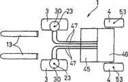
左右一对前车轮3,设置成可分别相对车身2换向90°(可换成正横向)。即,在车身2侧固定上下方向的筒构件21,相对该筒构件21(相对车身2侧)可绕纵轴心23自由转动地设置旋转构件22。A pair of
这里旋转构件22由成倒T字形且成壳体状的上位旋转部22A、和成C字形且成壳体状的下位旋转部22B构成,下位旋转部22B的上部连结于上位旋转部22A的下部成为一体。上位旋转部22A的上部插入筒构件21内由轴承装置24支承导向,借此构成为旋转构件22可绕纵向的纵轴心23自由转动。Here, the rotating
在所述下位旋转部22B的下端部分,通过轴承装置26可自由转动地安装着横向车轮轴25。左右一对前车轮3,借其轮缘3A分别通过连结件27安装于车轮轴25的外端,设置成连同旋转构件22绕纵轴心23自由转动。这时,前车轮3位于纵轴心23的大致正下方位置。A
左右一对前车轮3,分别与收纳进前车轮3的旋转范围3a内的行走驱动装置连动。即,以电动马达(行走驱动装置的一例)30的驱动轴31向下位于纵轴心23部分的状态,将该电动马达30设于所述筒构件21的上部(车身2侧)。而且在所述旋转构件22侧,设置使驱动轴31连动于车轮轴25的转动传递装置32。The left and right pair of
该转动传递装置32作为其一例由如下部分构成:在上位旋转部22A内并位于纵轴心23上部的上位转动轴33,使该上位转动轴33的上端部分连动于驱动轴31的连动构件34,设于该连动构件34部分的制动装置35,可自由转动地设于下位旋转部22B内的纵向下位转动轴36,使上位转动轴33的下端连动于下位转动轴36的上端的减速齿轮装置37,使下位转动轴36的下端连动于车轮轴25内端的锥齿轮装置38。This
在所述车身2侧,设有使所述旋转构件22转动的转动装置。即,左右的旋转构件22由连杆40等连结,而后由共同的旋转液压缸(作为转动装置之一例)41使其转动,左右前车轮3相互向相反方向换向,向着正横向。On the side of the
在所述车身2侧搭载着电池45,同时在该电池45上设控制器46。从控制器46伸出来的电缆(动力源供给零件)47,分别连接于所述电动马达30。这时,电缆47与旋转构件22一侧无关,从而可实现简单有效地配置。A
左右一对后车轮4,分别设置成可对车身2成90°换向(可换向成正横向)。即,左右一对后车轮4的轮缘4A,分别可自由空转地安装于倒L字形的旋转构件50的纵板部分,同时旋转构件50的横板部分可设置成,通过轴承51与纵轴52,相对车身2侧绕纵轴心53自由转动。这时后车轮4位于纵轴心53的大致正下方部分。由此,左右一对后车轮4构成为随动换向。A pair of
下边来说明上述第一实施例的作用。Next, the operation of the first embodiment described above will be described.
图1与图2的实线以及图3~图5示出了通常行走时的状态。这时左右前车轮3与左右后车轮4向着前后方向。这种状态的叉车1,由坐在驾驶室5的驾驶座15上的操作者操纵手柄16,可行走运动。The solid lines in FIGS. 1 and 2 and FIGS. 3 to 5 show the state during normal walking. At this time, the left and right
即,将电池45的电力由控制器46控制之后通过电缆47分别供给电动马达30,由驱动该电动马达30,通过转动传递装置32等对前车轮3进行正反驱动,从而可使叉车1前后行走运动。That is, the electric power of the
这时,将电动马达30的驱动轴31的转动,通过连动构件34、上位转动轴33、减速齿轮装置37、下位转动轴36、锥形齿轮装置38、车轮轴25可传递到前车轮3。而且借助使制动装置35动作,可使其适时停止。At this time, the rotation of the
而后,借操作升降用杆使升降液压缸11动作,可通过升降托架12等使叉13沿柱6升降运动,从而可进行所希望的叉车作业。另外,借操作摆动用杆使倾倒用液压缸8动作,可使柱6绕连结轴7转动,从而可通过升降托架12等改变叉13的姿势。Then, by operating the lifting rod to make the lifting
在从这样的通常行走状态切换到横向行走时,首先操作杆式横行模式开关(图中未示出),由使杆倾斜可使旋转液压缸41动作,通过连杆40使旋转构件22绕纵轴心23转动。因而像图1与图2虚线与图6所示,使前车轮3对车身2转90°(换向成正横向)。When switching from such a normal walking state to lateral travel, first operate the lever type traverse mode switch (not shown in the figure), and the rotary
这时,电动马达30被设于车身2侧,而后释放电动马达30且打开制动装置35,由此可通过旋转构件22轻快容易而平滑地进行前车轮3的90°换向。另外,由于前车轮3位于纵轴心23的大致正下方位置,前车轮3等变得很紧凑并可进行90°换向。At this time, the
这样,如由传感器感受到前车轮3所进行的换向,即前车轮3换向成正横向,指示灯亮,由此即可转入横行模式。Like this, feel the reversing that
从而,叉车1,由坐在驾驶室5中驾驶座15上的操作手操纵手柄16,和所述一样,可将电池45的电力经控制器46控制后通过电缆47分别供给电动马达30,驱动电动马达30、通过转动传递装置32等向正反向驱动前车轮3,因而可使叉车1左右横向行走。这时,左右一对后车轮4跟随转动。Thereby,
由这样进行横向行走,可通过叉13很容易地进行比如长物件的搬运。而且,使杆前后倾斜、并使旋转液压缸41微动、对前车轮3的角度进行微调,从而很容易进行横向行走的直进性修正。By traveling laterally in this way, for example, long objects can be easily transported by the
如依上述第一实施例,借左右一对前车轮3分别连动于收纳进前车轮3旋转范围3a内的纵向的电动马达30,可使其整体紧凑化,同时电缆47向固定于本体2的电动马达30的配设与旋转构件22侧无关,从而可简单有效地进行配设。As in the above-mentioned first embodiment, the pair of left and right
下边借图7~图10说明本发明第二实施例。而且,在第二实施例中,对于与所述第一实施例(图1~图6)相同的构成物或大致相同的构成物,给予相同的附图标记而省去详细说明。The second embodiment of the present invention will be described below with reference to FIGS. 7 to 10 . In addition, in the second embodiment, the same or substantially the same components as those of the first embodiment ( FIGS. 1 to 6 ) are denoted by the same reference numerals and detailed description thereof will be omitted.
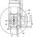
左右一对前车轮3,分别连动于收纳在前车轮3的旋转范围3a内的行走驱动装置。即,左右一对前车轮3,其轮缘3A分别通过连接件63直接安装于油压马达(行走驱动装置的一例)61的横向转动法兰(驱动轴的一例)62上,借此连动连结于油压马达61侧。在这里油压马达61形成为可收纳于旋转范围3a内的大小。The left and right pair of
油压马达61的安装是,横向安装于倒L字形的旋转构件64的纵板部分,同时旋转构件64的横板部分设置成,通过轴承装置65与纵轴66,可相对车身2绕纵轴心67自由转动。这时,前车轮3位于纵轴心67的大致正下方。The installation of the
左右的旋转构件64由连杆40等连结,而后,由共同的旋转液压缸(转动装置)41使其转动,因而左右前车轮3可相互换成相反方向,而向着正横向。Left and right rotating
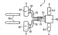
在所述车身2侧设发动机70,同时设由该发动机70驱动的一对油压泵71。而后,以各油压泵71分别对应一个油压马达61的状态、即成双泵双马达型的油压驱动系统(HST系统),通过配管(油压软管等)72将对应的油压泵71与油压马达61连通。An
下边来说明上述第二实施例的作用。Next, the operation of the above-mentioned second embodiment will be described.
图7、图8与图9示出了通常行走时的情况。这时,左右前车轮3与左右后车轮4向着前后方向。从而,可将由发动机70驱动的一对油压泵71来的油压,经驾驶室5的正反控制,通过配管72供给对应的油压马达61,借此正反驱动前车轮3,可使叉车1前后行走运动。Figure 7, Figure 8 and Figure 9 show the situation during normal walking. At this time, the left and right
在由这样的通常行走切换到横向行走时,如图10所示,使前车轮3对车身2进行90°换向(换向为正横向)。这样在进行前车轮3的换向之后,将油压泵71来的油压通过配管72供给对应的油压马达61,对前车轮3正反驱动,因而可使叉车1左右横向行走。这时,作为旋转脚轮形式的左右一对后车轮4也跟随换向。When switching from such normal running to lateral running, as shown in FIG. 10 , the
如依上述第二实施例,由于左右一对前车轮3,分别连动于收纳在前车轮3的旋转范围3a内的横向油压马达61,故使得整体上紧凑化。另外,作为叉车1的驱动形式,由于采用了双泵双马达型式的油压驱动系统,所述通常行走时的旋转,以方向盘操纵前车轮3的转动方向、转速差来进行,而进行横向行走时,以电气方式使旋转系统停止。As in the above-mentioned second embodiment, since the pair of left and right
下边,借图11~图14来说明本发明第三实施例。而且,在第三实施例中,对与所述第一实施例(图1~图6)相同的构成物或大致相同的构成物给予相同的附图标记,而省去详细说明。Next, a third embodiment of the present invention will be described with reference to FIGS. 11 to 14 . In addition, in the third embodiment, the same reference numerals are assigned to the same components as those in the first embodiment ( FIGS. 1 to 6 ) or substantially the same components, and detailed description thereof will be omitted.
在车身2侧设有使所述旋转构件22转动的前轮转动装置80。即,前轮转动装置80具有前轮横行用液压缸81,该前轮横行用液压缸81,其本体81a通过纵销82可自由摇动地安装于车身2侧,同时活塞杆81b,通过纵向连结销84可自由相对转动地连结于固定在单侧旋转构件22的连杆83。从左右旋转构件22连设的臂85之间通过连杆体86与连结销87可自由相对转动地连结着。A front wheel turning device 80 for turning the rotating
从而,由所述前轮横行用液压缸81的动作,通过连杆83使旋转构件22转动,由此,使单侧前车轮3绕纵轴心23换向成向着正横向,同时通过臂85与连杆体86等,使另一侧前车轮3绕旋转轴心23换向成向着正横向。即,借助前轮转动装置80,由共同的前轮横行用液压缸81的动作,使左右前车轮3相互向相反方向换向成向着正横向。由以上的81~87等构成了前轮转动装置80的一例。Thereby, by the action of the
左右一对后车轮4,设置成可分别相对车身2换向成90°(正横向)。即,左右一对后车轮4的轮缘4A,可分别通过横向车轴91等可自由空转地安装于倒L字形旋转构件90的纵板部分,另外,旋转构件90的横板部分可设置成,通过轴承92与纵轴93相对车身2侧绕纵轴心94自由转动。这时,后车轮4位于纵轴心94的大致正下方。A pair of
另外还设有可使左右一对后车轮4绕纵轴心94转动的后轮转动装置100,该后轮转动装置100,由换向用液压缸101与后轮横行用液压缸103等构成。Also be provided with the rear
即,换向用液压缸101,其本体101a配置于车宽方向,同时连结于其活塞101b的活塞杆101c向车宽方向两侧突出。而活塞杆101c突出的两端部,分别通过保持框体102固定于车身2侧,因而本体101a可自由移动于车宽方向。That is, in the
后轮横行用液压缸103是左右一对,其各自的本体103a通过连结件104与所述换向用液压缸101的本体101a连成一体(连结)。这时,连结于这些后轮横行用液压缸103的活塞103b的活塞杆103c,分别向车宽方向外侧突出。而连设于所述纵轴93上端的臂体105与活塞杆103c的突出端之间,通过连杆106以及纵向连结销107、108等自由相对转动地连结起来。The
借助上述后轮转动装置100,换向用液压缸101的动作,由其本体101a相对于固定的活塞杆101c向车宽方向移动来进行,而后轮横行用液压缸103的本体103a同换向用液压缸101的本体101a一体向车宽方向移动。这时,在保持框体102侧,设贯穿连结件104的导向体(图中未示出),因而,可由导向体对本体101a、103a的移动导向、并防止其转动。By means of the above-mentioned rear
所述换向用液压缸101的动作,借转动手柄16由轨道滚子(全液压式动力转向装置)来进行。而且后轮横行用液压缸103左右设置一对,在换向用液压缸101处于中立状态时使控制阀动作,由此可分别转动后车轮4,同时,在换向用液压缸101动作时成为规定的非动作姿势。The action of the
从而,由后轮横行用液压缸103的动作,通过连杆106与臂体105等使纵轴93转动,由此通过旋转构件90等使后车轮4绕纵轴心94换向为向着正横向。即,由后轮横行用液压缸103的动作,左右后车轮4相互朝同方向换向而向着正横向。由以上的101~108等,构成了可使左右一对后车轮4绕纵轴94转动的后轮转动装置100的一例。Thereby, by the action of the
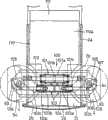
在所述车身2侧搭载电池110。该电池110由可在直进行走姿势时的两后车轮4间沿车长方向移动的宽幅的前部110a、和可位于横向行走姿势时的两后车轮4间的窄幅的后部110b构成为俯视呈T字形。车身2的后部侧构成于背面看成U字型的电池收纳部2a,这时,在电池收纳部2a的后端部分,形成了允许后车轮4转动的缺口部2b。而在电池收纳部2a后端敞开部2c,设有可自由装拆的盖体2d。A
从而,在两后车轮4取直进行走姿势且盖体2d成脱离状态下,电池110可从车身后方沿车长方向装拆,这时,宽幅的前部110a可在两后车轮4间无任何障碍地移动。另外,在安装着电池110的状态下,窄幅的后部110b位于两后车轮4间,因而可无障碍地进行两后车轮4向横向行走姿势的换向。Thereby, when the two
在所述电池110上,附设有控制器111。从控制器111来的电缆(动力源供给零件)112分别连接于所述电动马达30。这时,电缆112与旋转构件22侧无关,从而可简单而有效地进行配设。而后轮转动装置100配设为位于电池110上方。A
下边来说明上述第三实施例的作用。Next, the operation of the third embodiment described above will be described.
图11、图12的实线与图13、图14(a)示出了通常行走时的状态。这时,左右前车轮3与左右后车轮4向着前后方向。这样的叉车1,由坐在驾驶室5的驾驶座15上的操作者操纵手柄16即可行走运动。即,将电池110的电力经控制器111控制之后通过电缆112分别供给到电动马达30,由驱动该电动马达30,即可通过转动传递装置32等正反驱动前车轮3,因此可使叉车1前后行走运动。The solid lines in Fig. 11 and Fig. 12 and Fig. 13 and Fig. 14(a) show the state at the time of normal walking. At this time, the left and right
在所述行走运动时,根据手柄16的操纵而旋转。即,比如将手柄16向左侧转,换向用液压缸101的本体101a由轨道滚子向左侧动作,通过连结件104两后轮横行用液压缸103的本体103a一体地向左侧移动。这时,两后轮横行用液压缸103在规定的收缩限度内以非动作姿势起连杆状的作用。从而,两后轮横行用液压缸103向左侧的移动,通过连杆106传递到臂体105,因而使旋转构件90绕纵轴心94转动,使后车轮4换向并向左旋转。During the walking movement, it rotates according to the manipulation of the
另外,在使两后轮横行用液压缸103收缩运动到中途时,使两旋转构件90绕纵轴心94相互向相反方向转动,使左右后车轮4换向成其外缘稍稍向前方倾斜状,因而可在这种状态下旋转。而且与上述一样,比如可借使手柄16向右侧转动而使得向右旋转。In addition, when the
在从这样的通常行走状态切换到横向行走时,首先使换向用液压缸101成图13所示中立状(直进状)的位置。在此状态,比如操作杆式横行模式开关(图中未示出),使前轮转动装置80与后轮转动装置100动作。When switching from such a normal traveling state to lateral traveling, first, the
即,在前轮转动装置80中,操作杆式横行模式开关使杆倾斜,由此使前轮横行用液压缸81动作,通过连杆83使旋转构件22绕纵轴心23转动,因此如图11的虚线和图14(b)所示,使前车轮3对车身2换向90°(正横向)。That is, in the front wheel turning device 80, the lever type traverse mode switch is operated to tilt the lever, thereby actuating the front wheel traverse
而在后轮转动装置100中,由控制阀使两后轮横行用液压缸103收缩动作,活塞杆103c的退缩动作通过连杆106传递给臂体105,使旋转构件90绕纵轴心94转动,因而如图11、图12的虚线和图14(b)所示,使后车轮4对车身2换向90°(正横向)。In the rear
这样,由传感器测到前车轮3与后车轮4的换向、即前车轮3与后车轮4换向成正横向,指示灯亮,由此即可变为横行模式。Like this, detect the commutation of
从而,叉车1,由坐在驾驶室5的驾驶座15的操作人员操纵手柄16,和所述一样,可将电池110的电力经控制器111控制之后通过电缆112分别供给电动马达30,由驱动该电动马达30,通过转动传递装置32等正反驱动前车轮3转动,因此可使叉车1左右横向行走。这时,左右一对后车轮4跟随转动。Thereby,
在上述这样的叉车1中,电池110,由于在直进行走姿势的两后车轮4间宽幅的前部110a可沿车长方向无任何障碍地移动,故可从车身后方容易而迅速地进行对电池收纳部2a的装拆,因此可以很容易进行维护。搭载于电池收纳部2a的电池110,由于窄幅的后部110b位于两后车轮4间,故两后车轮4可毫无障碍地向横向行走姿势换向,而且,通过从座位15下方至车身2后端进行搭载,可使大型物件配设于车身2的下部,故可得到重心低稳定性好的叉车1。In the above-mentioned
在上述各实施例中,示出了作为作业车辆的配重型叉车1,但作为作业车辆,对大型搬运车、装载机、侧叉车等有着同样的作用。In each of the above-mentioned embodiments, the
如采用上述第一、第三实施例,由于左右一对前车轮3分别连动于收纳在前车轮3旋转范围3a内的纵向电动马达30,可使得整体上紧凑化;同时电缆47、112向固定于车身2的电动马达30的配设,可与旋转构件22侧无关地进行,从而可简单有效地进行配设。If the above-mentioned first and third embodiments are adopted, since the left and right pairs of
但也可以是将电动马达30安装于旋转构件22,使前车轮3的轮缘3A连动连结于横向驱动轴31的形式。在这种情况下,使前车轮3相对车身2换向90°时,由于前车轮3分别同电动马达30成一体,其换向可容易而平滑地进行。However, the
在上述各实施例中,示出了设置使左右一对前车轮3同时转动的共同转动装置41、80,但也可以是由各自的转动装置分别使左右一对前车轮3转动的形式。In each of the above-mentioned embodiments, the
在上述第二实施例中,左右一对前车轮3分别连动于收纳在前车轮3的旋转范围3a内的油压马达61;但作为行走驱动装置,也可以采用电动马达。In the above-mentioned second embodiment, the pair of left and right
在上述第一、第二实施例中,作为左右一对后车轮4,采用了跟随换向的旋转脚轮形式,但其也可以和前车轮3一样,如第二实施例那样,采用由液压缸等强制换向的形式。In the above-mentioned first and second embodiments, as a pair of left and right
在上述第三实施例中,示出了设置使左右一对后车轮4同时转动的共同的后轮转动装置100的形式;但也可以是左右一对后车轮4中,其一方的后车轮4由方向盘操纵的形式,而另一方的后车轮4采取小脚轮的形式。在这种情况下,当切换为横向行走时,由液压缸等对一方的后车轮4强制换向。In the above-mentioned third embodiment, the form in which a common rear
Claims (5)
Applications Claiming Priority (6)
| Application Number | Priority Date | Filing Date | Title |
|---|---|---|---|
| JP213581/2000 | 2000-07-14 | ||
| JP2000213581AJP2002029446A (en) | 2000-07-14 | 2000-07-14 | Working vehicle with traverse system |
| JP213581/00 | 2000-07-14 | ||
| JP221588/2000 | 2000-07-24 | ||
| JP2000221588AJP3919427B2 (en) | 2000-07-24 | 2000-07-24 | Work vehicle with traversing system |
| JP221588/00 | 2000-07-24 |
Publications (2)
| Publication Number | Publication Date |
|---|---|
| CN1450965A CN1450965A (en) | 2003-10-22 |
| CN100506588Ctrue CN100506588C (en) | 2009-07-01 |
Family
ID=26596013
Family Applications (1)
| Application Number | Title | Priority Date | Filing Date |
|---|---|---|---|
| CNB018127150AExpired - Fee RelatedCN100506588C (en) | 2000-07-14 | 2001-06-15 | Work vehicle with transverse travel system |
Country Status (6)
| Country | Link |
|---|---|
| US (1) | US6913102B2 (en) |
| EP (1) | EP1304279A1 (en) |
| KR (1) | KR100781655B1 (en) |
| CN (1) | CN100506588C (en) |
| TW (1) | TW579365B (en) |
| WO (1) | WO2002006111A1 (en) |
Families Citing this family (32)
| Publication number | Priority date | Publication date | Assignee | Title |
|---|---|---|---|---|
| US20050154504A1 (en)* | 2003-09-30 | 2005-07-14 | Nicholas Fenelli | Vehicles and control systems thereof with adjustable steering axes |
| WO2003029129A1 (en)* | 2001-10-03 | 2003-04-10 | Aisle-Master Limited | Articulated forklift truck |
| AU2002225300A1 (en)* | 2002-01-02 | 2003-07-30 | Combilift Research & Development Limited | Four-directional forklift truck |
| ITMO20040230A1 (en)* | 2004-09-14 | 2004-12-14 | Comer Ind Spa | 'TRANSMISSION GROUP FOR' DRIVING WHEELS OF VEHICLES PARTICULARLY TROLLEYS FOR THE HANDLING AND TRANSPORT OF MATERIALS '. |
| DE102005017723A1 (en)* | 2005-04-15 | 2006-10-26 | Zf Friedrichshafen Ag | Drive unit for an industrial truck |
| DE102005017736A1 (en)* | 2005-04-15 | 2006-12-14 | Zf Friedrichshafen Ag | Electric drive system for industrial trucks |
| TWI290881B (en)* | 2005-12-26 | 2007-12-11 | Ind Tech Res Inst | Mobile robot platform and method for sensing movement of the same |
| WO2008137704A1 (en) | 2007-05-07 | 2008-11-13 | Princeton Delivery Systems, Inc. | Four-way forklift with outwardly pivoting wheel arms |
| EP2090453A1 (en) | 2008-02-13 | 2009-08-19 | Kanzaki Kokyukoki MFG. Co., Ltd. | Wheel motor device |
| FR2928130B1 (en)* | 2008-02-29 | 2010-05-28 | Moulene | MOTORIZED VEHICLE WITH CONTROLLED INCLINATION. |
| US8818700B2 (en)* | 2008-02-29 | 2014-08-26 | Daniel Moulene | Motorised vehicle with controlled inclination |
| US8312957B1 (en)* | 2008-07-08 | 2012-11-20 | Stoltzfus Daniel R | Apparatus for moving concrete pump hoses |
| DE102009054727A1 (en)* | 2009-12-16 | 2011-06-22 | ZF Friedrichshafen AG, 88046 | Drive unit for forklift truck, has steering transmission connected with steering rim that is designed as steering hollow wheel, where lubricating oil within steering rim discharges heat produced by electronic component of unit |
| DE102009054726A1 (en)* | 2009-12-16 | 2011-06-22 | ZF Friedrichshafen AG, 88046 | Drive unit of a truck |
| JP2012017093A (en)* | 2010-06-09 | 2012-01-26 | Ntn Corp | Electric vehicle |
| JP5799879B2 (en)* | 2012-04-03 | 2015-10-28 | 株式会社豊田自動織機 | Battery powered forklift |
| CN103754284A (en)* | 2014-01-28 | 2014-04-30 | 浙江诺力机械股份有限公司 | Industrial vehicle capable of traveling in four directions and traveling mechanism of industrial vehicle |
| CN103963637B (en)* | 2014-04-29 | 2017-08-25 | 浙江吉利控股集团有限公司 | A kind of Integral steering drive axle and electric vehicle for vehicle |
| JP6382597B2 (en)* | 2014-06-27 | 2018-08-29 | Ntn株式会社 | vehicle |
| US10221056B2 (en)* | 2015-08-21 | 2019-03-05 | The Boeing Company | Component moving system and method |
| JP6350501B2 (en)* | 2015-12-08 | 2018-07-04 | 株式会社豊田自動織機 | Reach type forklift |
| JP6304225B2 (en)* | 2015-12-17 | 2018-04-04 | 株式会社豊田自動織機 | Standing forklift |
| FI128300B (en)* | 2018-09-03 | 2020-03-13 | Rocla Oyj | Steering of forklift trucks |
| JP2020166734A (en)* | 2019-03-29 | 2020-10-08 | 日本電産シンポ株式会社 | Dolly |
| DE102019108589A1 (en)* | 2019-04-02 | 2020-10-08 | Hubtex Maschinenbau Gmbh & Co. Kg | Steering method of an industrial truck and industrial truck |
| JP7318450B2 (en)* | 2019-09-24 | 2023-08-01 | 株式会社ジェイテクト | steering device |
| US11560053B2 (en)* | 2019-10-03 | 2023-01-24 | Toyota Motor Engineering & Manufacturing North America, Inc. | Electric vehicle comprising a vertical electric propulsion motor and method of making and using the same |
| US11447006B2 (en) | 2019-10-03 | 2022-09-20 | Toyota Motor Engineering & Manufacturing North America, Inc. | Electric or hybrid electric vehicle having adjustable vertical electric drive motor and method of making and using |
| JP7348093B2 (en)* | 2020-01-27 | 2023-09-20 | ダイムラー トラック エージー | Drive unit for electric trucks |
| CA3177997A1 (en)* | 2020-05-25 | 2021-12-02 | Heggebo Jorgen Djuve | Container handling vehicle which can load and/or unload itself |
| CN114987609B (en)* | 2022-04-18 | 2023-03-10 | 华南农业大学 | A four-wheel independent steering paddy field agricultural robot and its navigation method |
| US12427851B2 (en) | 2022-12-20 | 2025-09-30 | Cnh Industrial America Llc | Vehicle with wheel-mounted energy storage |
Citations (3)
| Publication number | Priority date | Publication date | Assignee | Title |
|---|---|---|---|---|
| US4823899A (en)* | 1986-07-10 | 1989-04-25 | Ashot Ashkelon Industries Ltd. | Steering apparatus |
| US4986387A (en)* | 1989-08-07 | 1991-01-22 | Teledyne Princeton, Inc. | Fork-lift truck having three drive wheels with third wheel steerable |
| CN2297437Y (en)* | 1997-06-09 | 1998-11-18 | 山东光明机器厂 | U shape storage battery balancing weight type lower seat fork-lift truck |
Family Cites Families (16)
| Publication number | Priority date | Publication date | Assignee | Title |
|---|---|---|---|---|
| JPS5284649A (en) | 1975-12-29 | 1977-07-14 | Suzuki Motor Co Ltd | Car steering apparatus |
| JPS52147834A (en) | 1976-06-01 | 1977-12-08 | Nippon Douki Kk | Vehicle |
| US4268216A (en)* | 1977-07-04 | 1981-05-19 | Fernand Copie | Load lifting and carrying machine |
| US4219094A (en)* | 1978-11-09 | 1980-08-26 | Rpc Corporation | Straddle crane apparatus |
| JPS6050624B2 (en) | 1980-05-20 | 1985-11-09 | 日産自動車株式会社 | vehicle steering system |
| US4498554A (en)* | 1982-05-03 | 1985-02-12 | Young Roy E | Highly maneuverable prime mover |
| US4557346A (en)* | 1984-03-16 | 1985-12-10 | Up-Right, Inc. | Steering and drive system |
| JP2829746B2 (en) | 1989-08-10 | 1998-12-02 | 株式会社ユーシン | Vehicle lateral movement steering system |
| US5213143A (en)* | 1991-06-06 | 1993-05-25 | Ag-Bag Corporation | Steering and propulsion mechanism for agricultural field vehicle |
| US5343974A (en)* | 1992-07-10 | 1994-09-06 | Rabek Jan W | An electrically powered motor vehicle |
| US5335739A (en)* | 1992-12-30 | 1994-08-09 | Ian Pieterse | Agricultural vehicle |
| JPH0769078A (en) | 1993-09-02 | 1995-03-14 | Nissan Motor Co Ltd | Battery fixing structure for electric vehicles |
| US5570754A (en)* | 1994-02-16 | 1996-11-05 | Stimson; Dwight S. | Tractor and trailer for moving loads in confined spaces |
| US5924512A (en)* | 1994-12-14 | 1999-07-20 | Fuji Electric Co., Ltd. | Omnidirectional vehicle and method of controlling the same |
| JP3199612B2 (en) | 1995-08-22 | 2001-08-20 | ティー・シー・エム株式会社 | Wheel drive circuit for traversable vehicles |
| US5983612A (en)* | 1996-11-01 | 1999-11-16 | Textron, Inc. | Removable battery tray system for an electrically powered bunker rake |
- 2001
- 2001-06-15CNCNB018127150Apatent/CN100506588C/ennot_activeExpired - Fee Related
- 2001-06-15USUS10/332,932patent/US6913102B2/ennot_activeExpired - Fee Related
- 2001-06-15WOPCT/JP2001/005159patent/WO2002006111A1/ennot_activeApplication Discontinuation
- 2001-06-15EPEP01941075Apatent/EP1304279A1/ennot_activeWithdrawn
- 2001-06-15KRKR1020037000351Apatent/KR100781655B1/ennot_activeExpired - Fee Related
- 2001-06-18TWTW090114747Apatent/TW579365B/ennot_activeIP Right Cessation
Patent Citations (3)
| Publication number | Priority date | Publication date | Assignee | Title |
|---|---|---|---|---|
| US4823899A (en)* | 1986-07-10 | 1989-04-25 | Ashot Ashkelon Industries Ltd. | Steering apparatus |
| US4986387A (en)* | 1989-08-07 | 1991-01-22 | Teledyne Princeton, Inc. | Fork-lift truck having three drive wheels with third wheel steerable |
| CN2297437Y (en)* | 1997-06-09 | 1998-11-18 | 山东光明机器厂 | U shape storage battery balancing weight type lower seat fork-lift truck |
Also Published As
| Publication number | Publication date |
|---|---|
| TW579365B (en) | 2004-03-11 |
| KR100781655B1 (en) | 2007-12-03 |
| US20030155163A1 (en) | 2003-08-21 |
| EP1304279A1 (en) | 2003-04-23 |
| KR20030038660A (en) | 2003-05-16 |
| WO2002006111A1 (en) | 2002-01-24 |
| US6913102B2 (en) | 2005-07-05 |
| CN1450965A (en) | 2003-10-22 |
Similar Documents
| Publication | Publication Date | Title |
|---|---|---|
| CN100506588C (en) | Work vehicle with transverse travel system | |
| US6688416B2 (en) | Working vehicle with transverse travel system | |
| JP3874595B2 (en) | Forklift with traversing system | |
| US6675927B1 (en) | Fork lift with laterally travelling system | |
| JP3919429B2 (en) | Work vehicle with traversing system | |
| JP2002046996A (en) | Work vehicle with traverse system | |
| JP2984319B2 (en) | Steering mechanism for aerial work vehicles | |
| JP3375569B2 (en) | Side fork type transfer vehicle | |
| JP2916194B2 (en) | Steering mechanism for aerial work vehicles | |
| JP3919427B2 (en) | Work vehicle with traversing system | |
| JP3121806B1 (en) | Forklift with traversing system | |
| JP3121809B1 (en) | Forklift with traversing system | |
| JP3403673B2 (en) | Side fork type transfer vehicle | |
| JP2984320B2 (en) | Steering mechanism for aerial work vehicles | |
| JP3140012B2 (en) | Forklift with traversing system | |
| JP3140005B2 (en) | Forklift with traversing system | |
| JP3140013B2 (en) | Forklift with traversing system | |
| JP2002029446A (en) | Working vehicle with traverse system | |
| JP3140014B2 (en) | Forklift with traversing system | |
| JP3249105B2 (en) | Work vehicle with traversing system | |
| JP3272339B2 (en) | Forklift with traversing system | |
| JPH0121904Y2 (en) |
Legal Events
| Date | Code | Title | Description |
|---|---|---|---|
| C06 | Publication | ||
| PB01 | Publication | ||
| C10 | Entry into substantive examination | ||
| SE01 | Entry into force of request for substantive examination | ||
| C14 | Grant of patent or utility model | ||
| GR01 | Patent grant | ||
| CF01 | Termination of patent right due to non-payment of annual fee | Granted publication date:20090701 Termination date:20140615 | |
| EXPY | Termination of patent right or utility model |