CN100502963C - injection device - Google Patents
injection deviceDownload PDFInfo
- Publication number
- CN100502963C CN100502963CCNB2005800346367ACN200580034636ACN100502963CCN 100502963 CCN100502963 CCN 100502963CCN B2005800346367 ACNB2005800346367 ACN B2005800346367ACN 200580034636 ACN200580034636 ACN 200580034636ACN 100502963 CCN100502963 CCN 100502963C
- Authority
- CN
- China
- Prior art keywords
- dose setting
- setting member
- dose
- injection device
- housing
- Prior art date
- Legal status (The legal status is an assumption and is not a legal conclusion. Google has not performed a legal analysis and makes no representation as to the accuracy of the status listed.)
- Expired - Fee Related
Links
- 238000002347injectionMethods0.000titleclaimsabstractdescription60
- 239000007924injectionSubstances0.000titleclaimsabstractdescription60
- 239000003814drugSubstances0.000claimsabstractdescription10
- 229940079593drugDrugs0.000claimsabstractdescription9
- 230000007246mechanismEffects0.000claimsdescription5
- NOESYZHRGYRDHS-UHFFFAOYSA-NinsulinChemical compoundN1C(=O)C(NC(=O)C(CCC(N)=O)NC(=O)C(CCC(O)=O)NC(=O)C(C(C)C)NC(=O)C(NC(=O)CN)C(C)CC)CSSCC(C(NC(CO)C(=O)NC(CC(C)C)C(=O)NC(CC=2C=CC(O)=CC=2)C(=O)NC(CCC(N)=O)C(=O)NC(CC(C)C)C(=O)NC(CCC(O)=O)C(=O)NC(CC(N)=O)C(=O)NC(CC=2C=CC(O)=CC=2)C(=O)NC(CSSCC(NC(=O)C(C(C)C)NC(=O)C(CC(C)C)NC(=O)C(CC=2C=CC(O)=CC=2)NC(=O)C(CC(C)C)NC(=O)C(C)NC(=O)C(CCC(O)=O)NC(=O)C(C(C)C)NC(=O)C(CC(C)C)NC(=O)C(CC=2NC=NC=2)NC(=O)C(CO)NC(=O)CNC2=O)C(=O)NCC(=O)NC(CCC(O)=O)C(=O)NC(CCCNC(N)=N)C(=O)NCC(=O)NC(CC=3C=CC=CC=3)C(=O)NC(CC=3C=CC=CC=3)C(=O)NC(CC=3C=CC(O)=CC=3)C(=O)NC(C(C)O)C(=O)N3C(CCC3)C(=O)NC(CCCCN)C(=O)NC(C)C(O)=O)C(=O)NC(CC(N)=O)C(O)=O)=O)NC(=O)C(C(C)CC)NC(=O)C(CO)NC(=O)C(C(C)O)NC(=O)C1CSSCC2NC(=O)C(CC(C)C)NC(=O)C(NC(=O)C(CCC(N)=O)NC(=O)C(CC(N)=O)NC(=O)C(NC(=O)C(N)CC=1C=CC=CC=1)C(C)C)CC1=CN=CN1NOESYZHRGYRDHS-UHFFFAOYSA-N0.000description11
- 102000004877InsulinHuman genes0.000description5
- 108090001061InsulinProteins0.000description5
- 229940125396insulinDrugs0.000description5
- 230000008878couplingEffects0.000description3
- 238000010168coupling processMethods0.000description3
- 238000005859coupling reactionMethods0.000description3
- 206010012601diabetes mellitusDiseases0.000description3
- 230000003993interactionEffects0.000description3
- 239000003795chemical substances by applicationSubstances0.000description2
- 238000012377drug deliveryMethods0.000description2
- 239000007788liquidSubstances0.000description2
- 238000000034methodMethods0.000description2
- 108090000623proteins and genesProteins0.000description2
- 238000007920subcutaneous administrationMethods0.000description2
- VOUAQYXWVJDEQY-QENPJCQMSA-N33017-11-7Chemical compoundOC(=O)CC[C@H](N)C(=O)N[C@@H](C)C(=O)N[C@@H](CCC(O)=O)C(=O)N[C@@H](CC(O)=O)C(=O)N[C@@H](CC(C)C)C(=O)N[C@@H](CCC(N)=O)C(=O)N[C@@H](C(C)C)C(=O)NCC(=O)N[C@@H](CCC(N)=O)C(=O)N[C@@H](C(C)C)C(=O)N[C@@H](CCC(O)=O)C(=O)N[C@@H](CC(C)C)C(=O)NCC(=O)NCC(=O)NCC(=O)N1CCC[C@H]1C(=O)NCC(=O)N[C@@H](C)C(=O)NCC(=O)N[C@@H](CO)C(=O)N[C@@H](CC(C)C)C(=O)N[C@@H](CCC(N)=O)C(=O)N1[C@H](C(=O)N[C@@H](CC(C)C)C(=O)N[C@@H](C)C(=O)N[C@@H](CC(C)C)C(=O)N[C@@H](CCC(O)=O)C(=O)NCC(=O)N[C@@H](CO)C(=O)N[C@@H](CC(C)C)C(=O)N[C@@H](CCC(N)=O)C(O)=O)CCC1VOUAQYXWVJDEQY-QENPJCQMSA-N0.000description1
- 108010075254C-PeptideProteins0.000description1
- 239000013543active substanceSubstances0.000description1
- 230000008859changeEffects0.000description1
- 210000000078clawAnatomy0.000description1
- 229940126534drug productDrugs0.000description1
- 230000009969flowable effectEffects0.000description1
- 239000012530fluidSubstances0.000description1
- 239000000499gelSubstances0.000description1
- 230000014509gene expressionEffects0.000description1
- 239000011521glassSubstances0.000description1
- 230000003054hormonal effectEffects0.000description1
- 229940088597hormoneDrugs0.000description1
- 239000005556hormoneSubstances0.000description1
- 238000010348incorporationMethods0.000description1
- 238000001746injection mouldingMethods0.000description1
- 239000000463materialSubstances0.000description1
- 238000002483medicationMethods0.000description1
- 238000012986modificationMethods0.000description1
- 230000004048modificationEffects0.000description1
- 235000016709nutritionNutrition0.000description1
- 230000037368penetrate the skinEffects0.000description1
- 239000000825pharmaceutical preparationSubstances0.000description1
- 102000004196processed proteins & peptidesHuman genes0.000description1
- 108090000765processed proteins & peptidesProteins0.000description1
- 102000004169proteins and genesHuman genes0.000description1
- 238000004064recyclingMethods0.000description1
- 239000007787solidSubstances0.000description1
- 239000002904solventSubstances0.000description1
- 239000007929subcutaneous injectionSubstances0.000description1
- 238000010254subcutaneous injectionMethods0.000description1
- 239000000126substanceSubstances0.000description1
Images


Classifications
- A—HUMAN NECESSITIES
- A61—MEDICAL OR VETERINARY SCIENCE; HYGIENE
- A61M—DEVICES FOR INTRODUCING MEDIA INTO, OR ONTO, THE BODY; DEVICES FOR TRANSDUCING BODY MEDIA OR FOR TAKING MEDIA FROM THE BODY; DEVICES FOR PRODUCING OR ENDING SLEEP OR STUPOR
- A61M5/00—Devices for bringing media into the body in a subcutaneous, intra-vascular or intramuscular way; Accessories therefor, e.g. filling or cleaning devices, arm-rests
- A61M5/178—Syringes
- A61M5/24—Ampoule syringes, i.e. syringes with needle for use in combination with replaceable ampoules or carpules, e.g. automatic
- A—HUMAN NECESSITIES
- A61—MEDICAL OR VETERINARY SCIENCE; HYGIENE
- A61M—DEVICES FOR INTRODUCING MEDIA INTO, OR ONTO, THE BODY; DEVICES FOR TRANSDUCING BODY MEDIA OR FOR TAKING MEDIA FROM THE BODY; DEVICES FOR PRODUCING OR ENDING SLEEP OR STUPOR
- A61M5/00—Devices for bringing media into the body in a subcutaneous, intra-vascular or intramuscular way; Accessories therefor, e.g. filling or cleaning devices, arm-rests
- A61M5/178—Syringes
- A61M5/31—Details
- A61M5/315—Pistons; Piston-rods; Guiding, blocking or restricting the movement of the rod or piston; Appliances on the rod for facilitating dosing ; Dosing mechanisms
- A61M5/31533—Dosing mechanisms, i.e. setting a dose
- A61M5/31545—Setting modes for dosing
- A61M5/31548—Mechanically operated dose setting member
- A61M5/3155—Mechanically operated dose setting member by rotational movement of dose setting member, e.g. during setting or filling of a syringe
- A61M5/31551—Mechanically operated dose setting member by rotational movement of dose setting member, e.g. during setting or filling of a syringe including axial movement of dose setting member
- A—HUMAN NECESSITIES
- A61—MEDICAL OR VETERINARY SCIENCE; HYGIENE
- A61M—DEVICES FOR INTRODUCING MEDIA INTO, OR ONTO, THE BODY; DEVICES FOR TRANSDUCING BODY MEDIA OR FOR TAKING MEDIA FROM THE BODY; DEVICES FOR PRODUCING OR ENDING SLEEP OR STUPOR
- A61M5/00—Devices for bringing media into the body in a subcutaneous, intra-vascular or intramuscular way; Accessories therefor, e.g. filling or cleaning devices, arm-rests
- A61M5/178—Syringes
- A61M5/31—Details
- A61M5/315—Pistons; Piston-rods; Guiding, blocking or restricting the movement of the rod or piston; Appliances on the rod for facilitating dosing ; Dosing mechanisms
- A61M5/31565—Administration mechanisms, i.e. constructional features, modes of administering a dose
- A61M5/31576—Constructional features or modes of drive mechanisms for piston rods
- A61M5/31583—Constructional features or modes of drive mechanisms for piston rods based on rotational translation, i.e. movement of piston rod is caused by relative rotation between the user activated actuator and the piston rod
- A61M5/31586—Constructional features or modes of drive mechanisms for piston rods based on rotational translation, i.e. movement of piston rod is caused by relative rotation between the user activated actuator and the piston rod performed by rotationally moving or pivoted actuator, e.g. an injection lever or handle
- A—HUMAN NECESSITIES
- A61—MEDICAL OR VETERINARY SCIENCE; HYGIENE
- A61M—DEVICES FOR INTRODUCING MEDIA INTO, OR ONTO, THE BODY; DEVICES FOR TRANSDUCING BODY MEDIA OR FOR TAKING MEDIA FROM THE BODY; DEVICES FOR PRODUCING OR ENDING SLEEP OR STUPOR
- A61M5/00—Devices for bringing media into the body in a subcutaneous, intra-vascular or intramuscular way; Accessories therefor, e.g. filling or cleaning devices, arm-rests
- A61M5/178—Syringes
- A61M5/24—Ampoule syringes, i.e. syringes with needle for use in combination with replaceable ampoules or carpules, e.g. automatic
- A61M2005/2403—Ampoule inserted into the ampoule holder
- A61M2005/2407—Ampoule inserted into the ampoule holder from the rear
- A—HUMAN NECESSITIES
- A61—MEDICAL OR VETERINARY SCIENCE; HYGIENE
- A61M—DEVICES FOR INTRODUCING MEDIA INTO, OR ONTO, THE BODY; DEVICES FOR TRANSDUCING BODY MEDIA OR FOR TAKING MEDIA FROM THE BODY; DEVICES FOR PRODUCING OR ENDING SLEEP OR STUPOR
- A61M5/00—Devices for bringing media into the body in a subcutaneous, intra-vascular or intramuscular way; Accessories therefor, e.g. filling or cleaning devices, arm-rests
- A61M5/178—Syringes
- A61M5/24—Ampoule syringes, i.e. syringes with needle for use in combination with replaceable ampoules or carpules, e.g. automatic
- A61M2005/2485—Ampoule holder connected to rest of syringe
- A61M2005/2488—Ampoule holder connected to rest of syringe via rotation, e.g. threads or bayonet
- A—HUMAN NECESSITIES
- A61—MEDICAL OR VETERINARY SCIENCE; HYGIENE
- A61M—DEVICES FOR INTRODUCING MEDIA INTO, OR ONTO, THE BODY; DEVICES FOR TRANSDUCING BODY MEDIA OR FOR TAKING MEDIA FROM THE BODY; DEVICES FOR PRODUCING OR ENDING SLEEP OR STUPOR
- A61M5/00—Devices for bringing media into the body in a subcutaneous, intra-vascular or intramuscular way; Accessories therefor, e.g. filling or cleaning devices, arm-rests
- A61M5/178—Syringes
- A61M5/24—Ampoule syringes, i.e. syringes with needle for use in combination with replaceable ampoules or carpules, e.g. automatic
- A61M5/2455—Ampoule syringes, i.e. syringes with needle for use in combination with replaceable ampoules or carpules, e.g. automatic with sealing means to be broken or opened
- A61M5/2466—Ampoule syringes, i.e. syringes with needle for use in combination with replaceable ampoules or carpules, e.g. automatic with sealing means to be broken or opened by piercing without internal pressure increase
- A—HUMAN NECESSITIES
- A61—MEDICAL OR VETERINARY SCIENCE; HYGIENE
- A61M—DEVICES FOR INTRODUCING MEDIA INTO, OR ONTO, THE BODY; DEVICES FOR TRANSDUCING BODY MEDIA OR FOR TAKING MEDIA FROM THE BODY; DEVICES FOR PRODUCING OR ENDING SLEEP OR STUPOR
- A61M5/00—Devices for bringing media into the body in a subcutaneous, intra-vascular or intramuscular way; Accessories therefor, e.g. filling or cleaning devices, arm-rests
- A61M5/178—Syringes
- A61M5/31—Details
- A61M5/315—Pistons; Piston-rods; Guiding, blocking or restricting the movement of the rod or piston; Appliances on the rod for facilitating dosing ; Dosing mechanisms
- A61M5/31533—Dosing mechanisms, i.e. setting a dose
- A61M5/31535—Means improving security or handling thereof, e.g. blocking means, means preventing insufficient dosing, means allowing correction of overset dose
- A61M5/31541—Means preventing setting of a dose beyond the amount remaining in the cartridge
- A—HUMAN NECESSITIES
- A61—MEDICAL OR VETERINARY SCIENCE; HYGIENE
- A61M—DEVICES FOR INTRODUCING MEDIA INTO, OR ONTO, THE BODY; DEVICES FOR TRANSDUCING BODY MEDIA OR FOR TAKING MEDIA FROM THE BODY; DEVICES FOR PRODUCING OR ENDING SLEEP OR STUPOR
- A61M5/00—Devices for bringing media into the body in a subcutaneous, intra-vascular or intramuscular way; Accessories therefor, e.g. filling or cleaning devices, arm-rests
- A61M5/178—Syringes
- A61M5/31—Details
- A61M5/315—Pistons; Piston-rods; Guiding, blocking or restricting the movement of the rod or piston; Appliances on the rod for facilitating dosing ; Dosing mechanisms
- A61M5/31565—Administration mechanisms, i.e. constructional features, modes of administering a dose
- A61M5/31576—Constructional features or modes of drive mechanisms for piston rods
- A61M5/31578—Constructional features or modes of drive mechanisms for piston rods based on axial translation, i.e. components directly operatively associated and axially moved with plunger rod
- A61M5/3158—Constructional features or modes of drive mechanisms for piston rods based on axial translation, i.e. components directly operatively associated and axially moved with plunger rod performed by axially moving actuator operated by user, e.g. an injection button
Landscapes
- Health & Medical Sciences (AREA)
- Vascular Medicine (AREA)
- Engineering & Computer Science (AREA)
- Anesthesiology (AREA)
- Biomedical Technology (AREA)
- Heart & Thoracic Surgery (AREA)
- Hematology (AREA)
- Life Sciences & Earth Sciences (AREA)
- Animal Behavior & Ethology (AREA)
- General Health & Medical Sciences (AREA)
- Public Health (AREA)
- Veterinary Medicine (AREA)
- Infusion, Injection, And Reservoir Apparatuses (AREA)
- Pharmaceuticals Containing Other Organic And Inorganic Compounds (AREA)
Abstract
Description
Translated fromChinese技术领域technical field
本发明涉及如注射笔等的设备,用于最好以皮下方式将药物输送到人体,尤其涉及具有可释放刻度筒的注射装置。The present invention relates to devices, such as injection pens, for the delivery of drugs to the human body, preferably subcutaneously, and more particularly to injection devices having a releasable graduated cartridge.
背景技术Background technique
在本发明的公开中,主要涉及通过注射胰岛素进行糖尿病的治疗,但这只是本发明的示例性使用。In the disclosure of the present invention, the treatment of diabetes by injecting insulin is mainly concerned, but this is only an exemplary use of the present invention.
注射笔主要用于必须经常自己注射的用户,例如患有糖尿病的人。对这种注射笔提出多种要求。剂量的设置必须容易且清楚,并且必须易于读取设置的剂量。必须能很顺畅地取消或改变错误设置的剂量,并且当注射该剂量时,剂量设置必须归零。当预填充的注射笔出现问题时,即储存器排空时抛弃注射笔,该注射笔还必须便宜并用适合于再循环的材料制成。Injection pens are mainly used by users who must often inject themselves, such as people with diabetes. Various demands are placed on such injection pens. The setting of the dose must be easy and clear, and the set dose must be easy to read. It must be possible to cancel or change an incorrectly set dose without a problem, and the dose setting must be reset to zero when the dose is injected. When there is a problem with a prefilled pen, ie discarding the pen when the reservoir is empty, the pen must also be inexpensive and made of materials suitable for recycling.
大多数剂量设置装置与和螺母配合的螺纹活塞杆一起工作,该螺母和活塞杆可以彼此相对转动。可以通过将螺母从止挡件拧开获得剂量设置,通过在注射期间向前按压活塞杆使该螺母返回,直到螺母构件抵靠该止挡件为止。通过其它剂量设置装置,其中一个元件,螺母或活塞杆保持不可转动,并且其它的元件允许根据设置剂量转动一设定角度,从而活塞杆通过螺母构件向前拧动一距离。Most dose setting devices work with a threaded piston rod cooperating with a nut which can rotate relative to each other. Dose setting may be achieved by unscrewing the nut from the stop, which is returned by pressing the piston rod forward during injection until the nut member abuts the stop. With other dose setting devices, one element, the nut or the piston rod, remains non-rotatable and the other element is allowed to turn a set angle according to the set dose, whereby the piston rod is screwed forward a distance through the nut member.
在用于分配设定剂量的大多数注射装置中,最好是活塞杆与在注射期间作用在其上的活塞恒定接合,从而防止倒吸。为了实现这一点,采取预防措施,防止活塞杆在最近方向上向后移动。In most injection devices for dispensing a set dose, it is desirable that the piston rod is in constant engagement with the plunger which acts on it during injection, so as to prevent suck back. To achieve this, precautions are taken to prevent the piston rod from moving backwards in the closest direction.
在US6004297中公开了现有输送设备。在附图11至13中公开的设备包括用于转动螺纹活塞的带键的导向件,从而活塞杆上的螺纹在连接到筒保持器上的螺母中向前拧动。该带键的导向件设置有连接在带键的导向件和筒保持器之间的单向棘齿机构,从而带键的导向件只能够相对于筒保持器在一个方向上转动。该棘齿机构具有初始阻力,导向件为了转动必须克服该阻力。该阻力设置得较大,足以克服转动剂量设置把手时所施加的扭矩,意味着只有足够的注射压力施加在剂量设置把手上才能克服阻力并使得驱动器转动。而且,刻度筒安装在该注射笔内部。该刻度筒由剂量设定构件支承,但是相对于剂量设定构件自由转动,并且当轴向移动时由外壳中的内螺纹迫使转动。设定的剂量可以通过外壳中的窗口看到。An existing delivery device is disclosed in US6004297. The apparatus disclosed in Figures 11 to 13 includes a keyed guide for turning the threaded piston so that the threads on the piston rod are threaded forward in the nut attached to the cartridge holder. The keyed guide is provided with a one-way ratchet mechanism connected between the keyed guide and the cartridge holder so that the keyed guide can only rotate in one direction relative to the cartridge holder. The ratchet mechanism has an initial resistance that the guide must overcome in order to rotate. The resistance is set high enough to overcome the torque applied when turning the dose setting handle, meaning that only sufficient injection pressure is exerted on the dose setting handle to overcome the resistance and cause the driver to turn. Moreover, the scale cylinder is installed inside the injection pen. The scale drum is supported by the dose setting member but is free to rotate relative to the dose setting member and is forced to rotate when moved axially by internal threads in the housing. The set dose can be seen through a window in the housing.
刻度筒和外壳之间的螺纹连接中的公差决定了显示的精确度。如果刻度筒在螺纹中存在例如小的松动,则会显示错误的剂量大小,然而如果螺纹连接太紧,则将难以压回剂量设定把手。Tolerances in the threaded connection between the scale cylinder and the housing determine the accuracy of the display. If there is eg a small looseness of the scale cylinder in the thread, the wrong dose size will be displayed, whereas if the thread connection is too tight, it will be difficult to press back the dose setting handle.
在WO04/078239中公开了类似的注射笔。该注射笔包括螺纹活塞杆,当转动时,该螺纹活塞杆在内部螺纹螺母中向前拧动。当向前轴向移动时,具有螺纹的驱动套筒转动活塞杆,该螺纹配合活塞杆的螺纹。该驱动套筒联接到剂量刻度套筒上,该剂量刻度套筒转动,以调节(dial up)剂量。该剂量刻度套筒从外壳中转出以设置剂量,并转回以释放设定的剂量。当剂量设定时,该驱动套筒与剂量刻度套筒一起转动,但是当注射设定的剂量时,防止该驱动套筒的转动。A similar injection pen is disclosed in WO04/078239. The injection pen includes a threaded piston rod which, when turned, is threaded forward in an internally threaded nut. When moved axially forward, a drive sleeve with threads that engage the threads of the piston rod turns the piston rod. The drive sleeve is coupled to a dose scale sleeve which turns to dial up the dose. The dose scale sleeve rotates out of the housing to set the dose and rotates back to release the set dose. The drive sleeve rotates with the dose scale sleeve when the dose is set, but is prevented from rotating when the set dose is injected.
在使用中,当剂量设定时,该剂量刻度套筒转出外壳,而当压回剂量刻度套筒以注射所设定剂量时,该剂量刻度套筒沿相反方向转动。从而,随着剂量刻度套筒拧出外壳,剂量刻度套筒上指示剂量大小的标记变得可以被用户看见。当注射药物时,用户可能偶尔会妨碍剂量刻度套筒的转动,例如通过向剂量刻度套筒施加侧向压力,这将增加压回剂量刻度套筒所需要的力。In use, the dose scale sleeve is rotated out of the housing when the dose is set and rotated in the opposite direction when the dose scale sleeve is pressed back to inject the set dose. Thus, as the dose scale sleeve is unscrewed out of the housing, the markings on the dose scale sleeve indicating the dose size become visible to the user. When injecting a medicament, the user may occasionally interfere with the rotation of the dose scale sleeve, for example by applying lateral pressure to the dose scale sleeve, which will increase the force required to press back the dose scale sleeve.
在US6221053中公开了另一注射笔。在该注射笔中,注射按钮与刻度筒整体形成,并绕设置在驱动器的外部上的螺纹转上或转下以设定剂量。为了注射设定的剂量,以轴向不可转动的运动推回组合的注射按钮和刻度筒,这迫使驱动器转动。由于驱动器具有与带键的活塞杆上的螺纹配合的内螺纹,所以带键的活塞杆通过外壳内部螺母构件中存在的键向前移动。由于刻度筒在注射期间不转动,所以设置沿笔的360度上展开的窗口。设置在驱动器中的第二窗口指示所设定的剂量。Another injection pen is disclosed in US6221053. In this injection pen, an injection button is integrally formed with a graduated cylinder and is turned up or down about a thread provided on the exterior of the driver to set a dose. To inject the set dose, the combined injection button and scale cylinder is pushed back with an axial non-rotatable movement, which forces the driver to turn. Since the driver has internal threads that mate with threads on the keyed piston rod, the keyed piston rod is moved forward by the key present in the nut member inside the housing. Since the graduated cylinder does not rotate during injection, a window spread over 360 degrees of the pen is provided. A second window provided in the driver indicates the set dose.
在此方案中,刻度指示在窗口展开的整个360度上都可见。因此,用户必须注意通过设置在驱动器中的额外窗口读取所设定的剂量。In this scheme, the tick marks are visible over the full 360 degrees of the window expansion. Therefore, the user has to take care to read the set dose through an extra window provided in the driver.
在US6004297和US6221053中公开的活塞杆驱动器基本上包括两个元件。第一元件配合带键的活塞杆,并且带有内螺纹的第二元件配合活塞杆的外螺纹。当第一元件和第二元件相对转动时,该活塞杆向前拧动。The piston rod drivers disclosed in US6004297 and US6221053 basically comprise two elements. The first element cooperates with the keyed piston rod, and the second element with an internal thread cooperates with the external thread of the piston rod. When the first member and the second member rotate relative to each other, the piston rod is screwed forward.
在US6004297中,第一元件为配合带键的活塞杆的活塞杆导向件,并且第二元件为带螺纹的螺母构件,该螺母构件在注射期间使得活塞杆向前转动。而在US6221053中,该第一元件为不可转动地连接到外壳上的带键的螺母构件,并且第二元件为带螺纹的驱动器。在后一种情况下,活塞杆不转动地向前移动。In US6004297 the first element is a piston rod guide which engages a keyed piston rod and the second element is a threaded nut member which causes the piston rod to turn forward during injection. Whereas in US6221053 the first element is a keyed nut member non-rotatably connected to the housing and the second element is a threaded driver. In the latter case, the piston rod moves forward without rotation.
如胰岛素等的某些药物是自己操作注射的,并且典型的糖尿病人需要在一天之中进行若干次胰岛素的皮下注射。由于这些药物的大多数注射都由用户自己在私人环境下进行,所以很需要非常简单也非常精确的注射装置。Certain medications, such as insulin, are self-administered, and a typical diabetic requires several subcutaneous injections of insulin throughout the day. Since most injections of these drugs are performed by the users themselves in a private setting, there is a need for very simple and very precise injection devices.
发明内容Contents of the invention
考虑到上述现有装置,本发明的目的是提供药物输送装置,它消除了现有技术中药物输送装置的缺点,并提供所设定剂量的更精确显示。In view of the prior art devices described above, it is an object of the present invention to provide a drug delivery device which eliminates the disadvantages of the prior art drug delivery devices and which provides a more precise indication of the set dose.
相对应地,设置注射装置,其中,在刻度筒不可转动地连接到剂量设定构件上,从而无论剂量设定构件何时从外壳中拧出,刻度筒都将一一对应地跟随该转动而不会有任何错动。然而,当剂量设定构件沿轴向回到其初始位置时,刻度筒为了返回其初始位置必须能够转动。这通过提供可释放连接器实现,由此刻度筒可从与剂量设定构件的不可转动连接释放。Correspondingly, an injection device is provided in which the scale cylinder is non-rotatably connected to the dose setting member so that whenever the dose setting member is unscrewed from the housing, the scale cylinder will follow the rotation in a one-to-one correspondence. There will be no mistakes. However, when the dose setting member is returned axially to its original position, the scale cylinder must be able to turn in order to return to its original position. This is achieved by providing a releasable connector whereby the scale cylinder can be released from the non-rotatable connection with the dose setting member.
通过刻度筒和剂量设定构件之间的不可转动联接,当设定剂量时,可避免这两个元件之间的任何空隙,并且通过剂量设定构件的轴向返回,确保了用户在注射期间无法接触任何转动部件。By the non-rotatable coupling between the scale drum and the dose setting member, any gap between these two elements is avoided when setting the dose, and by the axial return of the dose setting member, the user is assured of There is no access to any rotating parts.
在示例性实施例中,在具有非常小直径的螺纹中引导刻度筒,这限制了注射期间能量的损失。由于剂量设定构件和活塞杆导向件之间的驱动螺纹已经具有小直径,所以最好用于引导刻度筒的螺纹也具有小直径。In an exemplary embodiment, the scale cylinder is guided in a thread with a very small diameter, which limits energy loss during injection. Since the drive thread between the dose setting member and the piston rod guide already has a small diameter, preferably the thread for guiding the scale drum also has a small diameter.
引导刻度筒的支承管可以通过例如注射模塑与外壳整体形成,或者可以制成不可转动地连接到外壳上的单独构件。The support tube guiding the scale cylinder may be formed integrally with the housing, eg by injection moulding, or may be made as a separate component non-rotatably connected to the housing.
在另一不同的示例性实施例中,可释放连接器设置在剂量设定构件上的指向外的齿和设置在刻度筒内表面上的带齿环之间。指向外的齿和带齿环都具有较小的宽度、例如2至5毫米,从而当剂量设定构件和刻度筒相对彼此轴向移动例如2至5毫米时,连接器被释放。In a different exemplary embodiment, the releasable connector is provided between outwardly pointing teeth on the dose setting member and a toothed ring provided on the inner surface of the scale drum. Both the outwardly pointing teeth and the toothed ring have a small width,
因此,为了释放带齿接合,刻度筒和剂量设定构件必须能够彼此相对轴向移动。Therefore, in order to release the toothed engagement, the scale drum and the dose setting member must be able to move axially relative to each other.
除了使刻度筒和剂量设定构件能够相对彼此轴向移动,该剂量设定构件也可以分成两部分。第一部分连接到按钮上并且第二部分轴相连接到刻度筒上,从而该第二部分和刻度筒在轴向上以一一对应的关系彼此跟随。In addition to enabling axial movement of the scale drum and the dose setting member relative to each other, the dose setting member may also be split into two parts. The first part is connected to the button and the second part is axially connected to the scale cylinder, so that the second part and the scale cylinder follow each other axially in a one-to-one relationship.
可释放联接器在本实施例中设置在第一剂量设定构件和刻度筒之间。当第一剂量设定构件相对于第二剂量设定构件和刻度筒轴向移动时,设置在第一剂量设定构件上的指向内的齿滑出与设置在刻度筒的内侧表面上的带齿环的接合,并且随着第一剂量设定构件和第二剂量设定构件在轴向上在远端方向上移动,刻度筒相对于这些构件自由转动。A releasable coupling is in this embodiment provided between the first dose setting member and the graduated cylinder. When the first dose setting member is moved axially relative to the second dose setting member and the scale cylinder, the inwardly pointing teeth provided on the first dose setting member slide out of the band provided on the inside surface of the scale cylinder engagement of the toothed rings, and as the first and second dose setting members are moved axially in the distal direction, the scale cylinder is free to rotate relative to these members.
在另一示例性实施例中,防护罩设置在按钮和外壳之间。该防护罩不可转动但可滑动地安装在外壳中。在其近端处,该防护罩通过可分离的连接器联接到按钮上,从而按钮与该防护罩可转动地连接或可转动地分离。In another exemplary embodiment, a shield is disposed between the button and the housing. The shield is non-rotatably but slidably mounted in the housing. At its proximal end, the shield is coupled to the button by a detachable connector so that the button is rotatably connected to or rotatably disconnected from the shield.
该可分离连接器最好由设置在防护罩近端上的多个齿形成,该齿可接合设置在按钮内侧上的类似齿,从而当预定压力施加在按钮的近端上时,按钮连接,并且当没有或只有很小压力施加时,按钮分离。The separable connector is preferably formed by a plurality of teeth provided on the proximal end of the shield which engage similar teeth provided on the inside of the button so that when a predetermined pressure is applied to the proximal end of the button, the button connects, And when no or only little pressure is applied, the button detaches.
“注射笔”通常是一机构,即具有有点像用于书写的笔那样的椭圆形或伸长形的用户推动注射设备。尽管这种笔通常具有管状横截面,但是它们也能够很容易具有不同横截面,如三角形、矩形或正方形。An "injection pen" is generally a mechanism, a user-push injection device having an oval or elongated shape somewhat like a pen for writing. Although such pens generally have a tubular cross-section, they could just as easily have a different cross-section, such as triangular, rectangular or square.
在此,术语“药物”包括任何含药物的可流动药品,如液体、溶剂、凝胶体或微悬浮物,它能够以受控的方式通过如空心针之类的输送装置。代表性的药物包括如肽、蛋白质(例如胰岛素、胰岛素类似物和C肽)之类的药剂、和激素、生物衍生或活性剂、激素和基因基试剂、营养处方和处于固体(配制的)或液体形式的其它物质。As used herein, the term "drug" includes any drug-containing flowable drug product, such as a liquid, solvent, gel or microsuspension, which is capable of passing in a controlled manner through a delivery device such as a hollow needle. Representative drugs include agents such as peptides, proteins (e.g., insulin, insulin analogs, and C-peptide), and hormones, biologically derived or active agents, hormonal and gene-based agents, nutritional prescriptions, and in solid (formulated) or Other substances in liquid form.
对应地,术语“皮下”注射包括经皮下输送到对象物的任何方法。Correspondingly, the term "subcutaneous" injection includes any method of subcutaneous delivery to a subject.
而且,术语“注射针”限定适合于为了输送或去除液体而穿透物体的皮肤的穿刺构件。Furthermore, the term "injection needle" defines a piercing member adapted to penetrate the skin of an object for the purpose of delivering or removing a fluid.
此处所引用的所有参考文献(包括出版物、专利申请和专利)都通过引用整体合并进来,并且仿佛每个参考文献都单独和特别表示将通过引用合并,并在此整体阐明。All references (including publications, patent applications, and patents) cited herein are hereby incorporated by reference in their entirety as if each reference were individually and specifically indicated to be incorporated by reference and were set forth in their entirety herein.
所有的标题或子标题此处都只是出于方便而使用,不应当以任何方式构成对本发明的限制。All headings or subheadings are used herein for convenience only and should not be construed as limiting the invention in any way.
任何和所有例子或者此处提供的示例性语言(例如,如)的使用都仅仅是为了更好地说明本发明,除非另外声明,否则不对本发明的范围构成限定。说明书中的任何语言都不应当构成表示实现本发明的所需要的任何非声明要素。此处专利文件的引用和合并只是出于方便的目的,并不反应这些专利文件的有效性、专利性和/或可执行性。The use of any and all examples, or exemplary language (eg, such as) provided herein, is intended merely to better illuminate the invention and does not pose a limitation on the scope of the invention unless otherwise claimed. No language in the specification should be construed as indicating any non-declared element as essential to the practice of the invention. The citation and incorporation of patent documents herein is for convenience only and does not reflect the validity, patentability and/or enforceability of these patent documents.
本发明包括适用法律所允许的所附权利要求所述主题的所有修改和等效物。This invention includes all modifications and equivalents of the subject matter recited in the claims appended hereto as permitted by applicable law.
附图说明Description of drawings
下面,将结合优选实施例并参照附图更加完整地解释本发明,其中:Below, the present invention will be explained more fully in conjunction with preferred embodiments and with reference to the accompanying drawings, wherein:
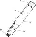
图1示出了注射装置的透视图。Figure 1 shows a perspective view of the injection device.
图2示出了不带有剂量设定的注射装置的剖视图。Figure 2 shows a cross-sectional view of the injection device without dose setting.
图3示出了带有剂量设定的注射装置的剖视图。Figure 3 shows a cross-sectional view of the injection device with dose setting.
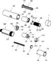
图4示出了注射装置的部分分解视图。Figure 4 shows a partially exploded view of the injection device.
图5示出了图4中所示的部件的透视图。FIG. 5 shows a perspective view of the components shown in FIG. 4 .
为了清楚而示意性地示出并简化附图,并且附图中只示出了为了理解本发明所必需的细节,而省略了其它细节。自始至终,相同的附图标记用于相同或相对应的部件。The drawings are shown schematically and simplified for the sake of clarity, and only details necessary for understanding the invention are shown in the drawings, while other details are omitted. Throughout, the same reference numerals are used for identical or corresponding parts.
具体实施方式Detailed ways
当在下面术语中使用如“上”和“下”、“右”和“左”、“水平的”和“竖直的”、“顺时针”和“逆时针”或类似相关表达时,它们仅指所附附图而并非指使用的实际情况。所示附图是示意性的,出于此原因,不同结构的构造以及它们的相关尺寸都只是起到说明性目的。When terms such as "upper" and "lower", "right" and "left", "horizontal" and "vertical", "clockwise" and "counterclockwise" or similar related expressions are used in the following terms, they Refers only to the attached drawings and not to the actual situation in use. The shown figures are schematic, for which reason the configuration of the different structures as well as their relative dimensions are for illustrative purposes only.
在上下文中,为了方便而限定所附附图中的术语“远端”表示承载注射针的注射装置的端部,而术语“近端”表示远离注射针的相对端部。In this context, the term "distal end", which is defined for convenience in the accompanying figures, means the end of the injection device carrying the injection needle, while the term "proximal end" means the opposite end away from the injection needle.
附图1公开了包括外壳30和筒保持器100的用户推动的注射笔。外壳30设置有窗口35,通过转动剂量设定按钮1,可以通过该窗口看到剂量设定。筒保持器100在其远端处设置有螺纹102,用于将注射针固定到注射笔上。FIG. 1 discloses a user-push injection pen comprising a
在附图2至5中详细公开了该注射笔的内部。The interior of the injection pen is disclosed in detail in accompanying
按钮1设置在注射装置的近端处,并通过第一剂量设定构件20的近端中的多个未示出的突起进入狭缝24而连接到第一剂量设定构件20上。按钮1的裙部3的内侧表面由防护罩10的外侧表面以可转动的方式支承。The
第一剂量设定构件20可转动地连接到第二剂量设定装置70上。该第一剂量设定构件20位于注射笔的近端处,并且第二剂量设定构件在远端方向上设置在下游。The first
防护罩10可在外壳30中轴向滑动,但是由在轨道31中滑动的突起11相对于外壳30锁定转动。防护罩10近端上的防护罩齿12的边缘与设置在按钮1内侧上的按钮齿2的相应边缘相互作用。当无压力作用在按钮1上时,按钮1能够相对于防护罩10转动,但是当例如在注射期间作用压力时,按钮齿2和防护罩齿12之间的相互作用锁定按钮1相对于防护罩10的转动。当注射按钮1相对于防护罩10转动时,由滑过防护罩齿12的按钮齿2而产生咔嗒声。按钮齿2和防护罩齿12的数量最好使得所调节的每个国际单位胰岛素都听到一声咔嗒声。The
外壳30具有指向内的凸缘32,该凸缘承载指向近端方向的支承管33。指向内的凸缘32示出为与外壳30模制成整体,但是也可以是插入到外壳32中的单独部件。支承管32位于其外侧上、即指向外壳30的内侧,并设置有支承螺纹34。该支承螺纹34通过位于刻度筒80的内侧上的相应螺纹84接合。The
活塞杆40对中地位于外壳30内部。该活塞杆40具有配合螺母50内部的螺母螺纹53的活塞杆螺纹41、和配合活塞杆导向件60中的内部键62的键42,从而当活塞杆导向件60转动时,活塞杆40在螺母50中向前旋拧。螺母50通过多个凸起部分52不可转动地固定到外壳30上,该凸起部分与外壳30的内表面上的多个未示出的狭缝接合。The
位于螺母50和活塞杆导向件60之间的棘齿机构51、61起到单向连接器的作用。活塞杆导向件60在其远端处设置有至少一个爪61,该爪与设置在螺母50内侧的螺母齿51的边缘接合。螺母齿51和爪61的相互作用防止活塞杆导向件60在将活塞杆40向注射装置后方拧动的方向上转动。在所公开的实施例中,禁止的方向为逆时针方向。A
活塞杆导向件60在其外侧上设置有导向螺纹63,该导向螺纹与第二剂量设定构件70的内螺纹73配合,使得第二剂量设定构件70可能相对于活塞杆导向件60上下旋动。The
通过与第二剂量设定构件70近端上的狭槽71接合的第一剂量设定构件20远端上的凸缘21,第二剂量设定构件70可转动地连接到第一剂量设定构件20上。而且,第二剂量设定构件70上的凸缘72进入第一剂量设定构件20上的狭槽22中,从而防止第一剂量设定构件20相对于第二剂量设定构件70转动。The second
第一剂量设定构件20远端上的凸缘21设置有指向外的齿23,该齿能够与设置在刻度筒80内部的筒刻度齿83的内环接合。The
而且,第二剂量设定构件70的近端设置有用于弹簧90的平台74。弹簧90的相对端置靠在位于防护罩10的内侧上的远端凸边(collar)13上,从而在相反方向上推动防护罩10和第二剂量设定构件70。Furthermore, the proximal end of the second
平台74的远端侧形成颈部75,该颈部固定刻度筒80的筒刻度齿83,将刻度筒80形成为第二剂量设定构件70的从动装置,即刻度筒80跟随第二剂量设定构件70的轴向移动。The distal side of the
由于第二剂量设定构件70和刻度筒80轴向联接到一起,所以弹簧90能够置于在刻度筒80的近端上,而不是第二剂量设定构件70的平台74上。Since the second
弹簧90在近端方向上推动防护罩10时,也推动与第一剂量设定构件20连接的注射按钮2。通过刻度筒80上的凸缘85,指向外的齿23的边缘锁定近端方向上的移动,从而不管来自弹簧90的压力如何,第一剂量设定构件20都保持其位置。When the
弹簧90将第一剂量设定构件20和第二剂量设定构件70分开大于按钮齿2和防护罩齿12的高度的距离,从而当第一剂量设定构件20压靠在第二剂量设定构件70上而将指向外的齿23移出与筒刻度齿83的接合时,按钮齿2将接合防护罩齿12,由此防止第一剂量设定构件20相对于防护罩10转动。The
为了设定剂量,用户握住外壳30,并在顺时针方向上转动按钮1。第一剂量设定构件20同时转动,并由于凸缘71和凸缘21之间的相互作用而迫使第二剂量设定构件70转动。第一剂量设定构件20上的指向外的齿23接合刻度筒80上的齿83,这使得刻度筒80也在顺时针方向上转动。To set a dose, the user holds the
现在转动锁定的第一剂量设定构件20、第二剂量设定构件70和刻度筒80通过刻度筒80内部的内螺纹84绕支承管33上的支承螺纹34转动上升。第二剂量设定构件70绕导向螺纹63转动上升,该导向螺纹具有与支承螺纹34相同的节距。刻度筒80在其远端处抵靠第二剂量设定构件70,从而将第二剂量设定构件70推到导向螺纹63上方。The now rotationally locked first
通过外壳30中(最好设置有放大镜)的开口32可以看到刻度筒80上的未示出标记。Markings (not shown) on the
注射按钮1在两个方向上都可以转动;在第一方向上,剂量的大小随着第一剂量设定构件20、第二剂量设定构件70和刻度筒80绕支承螺纹34转动上升而增大。在相反方向上,第一剂量设定构件20、第二剂量设定构件70和刻度筒80绕支承螺纹34向下调节,从而降低设定的剂量。The
当已经设定足够剂量时,用户通过将注射按钮2推回其轴向移动的初始位置而排出设定的剂量。When a sufficient dose has been set, the user expels the set dose by pushing the
注射按钮1上的齿2与相对于外壳30锁定转动的防护罩10上的齿12接合,从而防止第一剂量设定构件20相对于外壳30转动。
当第一剂量设定构件20轴向移动直到指向外的齿23位于狭槽71的近端为止,刻度筒80和第一剂量设定构件20之间的可释放联接才被释放。注射按钮1上的进一步的压力将第一剂量设定构件20和第二剂量设定构件70都向前推动。由于导向杆螺纹63和第二剂量设定构件70的内螺纹73之间的接合,该轴向的非转动的向前移动迫使活塞杆导向件60在顺时针方向上转动。The releasable coupling between the
活塞杆导向件60的转动迫使活塞杆40也在顺时针方向上转动,并在螺母50的螺纹53中向前拧动。Rotation of the
由于刻度筒80锁定在颈部75中,并在支承螺纹34中受到导向,所以它转回其初始位置。该转动发生在逆时针方向上。Since the
螺母110位于第一剂量设定构件20上,并通过内螺纹111与第一剂量设定构件20上的外螺纹25螺纹连接。通过在位于防护罩10内侧上的纵向狭槽13中受到导向的突起113,螺母110同时不可转动地连接到防护罩10上。The
当剂量设定时,第一剂量设定构件20相对于防护罩10和螺母110转动,使得螺母从近端起始点在远端方向上向前移动。螺母110向前移动的距离与所设定的剂量大小有关。When a dose is set, the first
当注射设定的剂量时,螺母110轴向向前移动与第一剂量设定构件20和防护罩10相同的距离。因此,螺母110在外螺纹25上的位置与储存器中药物的残余含量有关。When a set dose is injected, the
当螺母110到达平行于注射装置的纵向轴线的螺纹25的远端26时,螺母110无法再进一步拧动,并且禁止第一剂量设定构件20进一步转动。在WO01/019434中提供了这种剂量端部特征的更加详细的描述,其通过引用合并进来。When the
在前面已经示出了某些优选实施例,但是应当强调的是,本发明不仅局限于此,而是可以以所附权利要求中限定的主题范围内的其它方式实现。In the foregoing certain preferred embodiments have been shown, but it should be emphasized that the invention is not restricted thereto but can be implemented in other ways within the scope of the subject-matter defined in the appended claims.
Claims (9)
Translated fromChineseApplications Claiming Priority (2)
| Application Number | Priority Date | Filing Date | Title |
|---|---|---|---|
| EP04388068.1 | 2004-10-11 | ||
| EP04388068AEP1645301A1 (en) | 2004-10-11 | 2004-10-11 | Injection device |
Publications (2)
| Publication Number | Publication Date |
|---|---|
| CN101039712A CN101039712A (en) | 2007-09-19 |
| CN100502963Ctrue CN100502963C (en) | 2009-06-24 |
Family
ID=34931961
Family Applications (1)
| Application Number | Title | Priority Date | Filing Date |
|---|---|---|---|
| CNB2005800346367AExpired - Fee RelatedCN100502963C (en) | 2004-10-11 | 2005-10-06 | injection device |
Country Status (10)
| Country | Link |
|---|---|
| US (1) | US8608709B2 (en) |
| EP (2) | EP1645301A1 (en) |
| JP (1) | JP4906730B2 (en) |
| KR (1) | KR20070065878A (en) |
| CN (1) | CN100502963C (en) |
| AU (1) | AU2005293624A1 (en) |
| CA (1) | CA2583388A1 (en) |
| IL (1) | IL182296A0 (en) |
| RU (1) | RU2007112678A (en) |
| WO (1) | WO2006040296A2 (en) |
Cited By (1)
| Publication number | Priority date | Publication date | Assignee | Title |
|---|---|---|---|---|
| CN103547302A (en)* | 2011-03-25 | 2014-01-29 | 赛诺菲-安万特德国有限公司 | Dose Setting Mechanism and Injection Device |
Families Citing this family (79)
| Publication number | Priority date | Publication date | Assignee | Title |
|---|---|---|---|---|
| US6663602B2 (en) | 2000-06-16 | 2003-12-16 | Novo Nordisk A/S | Injection device |
| GB0304822D0 (en) | 2003-03-03 | 2003-04-09 | Dca Internat Ltd | Improvements in and relating to a pen-type injector |
| ATE444090T1 (en) | 2004-10-21 | 2009-10-15 | Novo Nordisk As | SELECTION MECHANISM FOR A ROTARY PIN |
| CN101068586B (en) | 2004-12-01 | 2011-05-25 | 诺和诺德公司 | injection device |
| US20090043264A1 (en) | 2005-04-24 | 2009-02-12 | Novo Nordisk A/S | Injection Device |
| CN101400394B (en) | 2006-03-10 | 2012-07-04 | 诺沃-诺迪斯克有限公司 | An injection device having a gearing arrangement |
| JP5062768B2 (en) | 2006-03-10 | 2012-10-31 | ノボ・ノルデイスク・エー/エス | INJECTION DEVICE AND METHOD FOR REPLACING CARTRIDGE OF THE DEVICE |
| ATE458517T1 (en) | 2006-05-16 | 2010-03-15 | Novo Nordisk As | TRANSMISSION MECHANISM FOR AN INJECTION DEVICE |
| JP5253387B2 (en)* | 2006-05-18 | 2013-07-31 | ノボ・ノルデイスク・エー/エス | Injection device with mode locking means |
| DE102006038102A1 (en)* | 2006-08-14 | 2008-02-21 | Tecpharma Licensing Ag | Threaded rod or piston rod for injection device i.e. fixed-dose pen, has four teeth and outer thread, where intervention unit of device is engaged in grooves to hold rod in rotation position or to rotate rod in preset turn by grooves |
| HUE060243T2 (en) | 2006-09-15 | 2023-02-28 | Ypsomed Ag | Injection device comprising an improved delivery element |
| CA2564061A1 (en)* | 2006-10-16 | 2008-04-16 | Duoject Medical Systems Inc. | Reconstitution system for mixing the contents of a vial containing a first substance with a second substance stored in a cartridge |
| BRPI0809265A2 (en) | 2007-03-23 | 2014-10-07 | Novo Nordisk As | INJECTION DEVICE INCLUDING A TIGHTENING NUT |
| BRPI0817907B8 (en)* | 2007-10-02 | 2021-06-22 | Lamodel Ltd | apparatus for administering a substance to an individual |
| WO2009080775A1 (en)* | 2007-12-20 | 2009-07-02 | Novo Nordisk A/S | Injection device for delivering a fixed dose of liquid drug |
| WO2009150028A1 (en)* | 2008-05-26 | 2009-12-17 | Novo Nordisk A/S | Improved injection device |
| US8376993B2 (en)* | 2008-08-05 | 2013-02-19 | Antares Pharma, Inc. | Multiple dosage injector |
| EP2373361B1 (en) | 2008-10-24 | 2012-09-12 | Novo Nordisk A/S | Dial-down mechanism for wind-up pen |
| US9545483B2 (en)* | 2008-12-02 | 2017-01-17 | Sanofi-Aventis Deutschland Gmbh | Drive assembly suitable for use in a medication delivery device and medication delivery device |
| TWI530306B (en) | 2009-06-02 | 2016-04-21 | 賽諾菲阿凡提斯德意志有限公司 | Drug delivery device assembly and drug delivery device |
| PL214940B1 (en) | 2009-07-31 | 2013-09-30 | Lozano Platonoff Alberto | Indication mechanism of an automatic applicator, especially for insulin |
| GB0918145D0 (en) | 2009-10-16 | 2009-12-02 | Owen Mumford Ltd | Injector apparatus |
| PL215310B1 (en) | 2009-10-30 | 2013-11-29 | Kappa Medilab Spolka Z Ograniczona Odpowiedzialnoscia | Automatic applicator, especially for insulin |
| ES2749395T3 (en) | 2009-11-20 | 2020-03-20 | Becton Dickinson Co | Injection device without the need for a gear |
| US11577029B2 (en) | 2012-03-15 | 2023-02-14 | Becton, Dickinson And Company | Multiple use disposable injection pen |
| EP3878495B1 (en) | 2011-03-16 | 2024-06-12 | Becton, Dickinson and Company | Multiple use disposable injection pen |
| US12350474B2 (en) | 2011-03-16 | 2025-07-08 | Becton, Dickinson And Company | Multiple use disposable injection pen |
| TWI595904B (en)* | 2011-03-25 | 2017-08-21 | 賽諾菲阿凡提斯德意志有限公司 | Dose setting mechanism and injection device |
| CA2849806A1 (en) | 2011-09-22 | 2013-03-28 | Abbvie Inc. | Automatic injection device |
| RU2620351C2 (en) | 2011-09-22 | 2017-05-24 | Эббви Инк. | Automated injector |
| JP6069351B2 (en) | 2011-12-29 | 2017-02-01 | ノボ・ノルデイスク・エー/エス | Torsion spring type automatic syringe with dial-up / dial-down administration mechanism |
| WO2013110538A1 (en) | 2012-01-27 | 2013-08-01 | Novo Nordisk A/S | Injection device with a sliding scale |
| IN2014DN07773A (en) | 2012-03-15 | 2015-05-15 | Becton Dickinson Co | |
| ES2623081T3 (en) | 2012-04-17 | 2017-07-10 | Carebay Europe Ltd | Medication Administration Device |
| CH706567A2 (en) | 2012-05-16 | 2013-11-29 | Tecpharma Licensing Ag | Improved device to set a dose a limiting mechanism for an apparatus for administering a product. |
| WO2014005808A1 (en)* | 2012-07-06 | 2014-01-09 | Carebay Europe Ltd | Medicament delivery device |
| DK3308815T3 (en) | 2013-01-15 | 2021-01-18 | Sanofi Aventis Deutschland | PENTYPE MEDICINE INJECTION DEVICE WITH ABSOLUTELY ANGLE DOSAGE ENCODER MECHANISM |
| CN105163778B (en)* | 2013-04-10 | 2019-03-15 | 赛诺菲 | Limiters mechanisms and injection device with the limiters mechanisms |
| DK2983735T3 (en)* | 2013-04-10 | 2021-03-01 | Sanofi Sa | DRIVE MECHANISM FOR A MEDICINE ADMINISTRATIVE DEVICE |
| MX2015014293A (en) | 2013-04-10 | 2015-12-08 | Sanofi Sa | Injection device. |
| TW201511785A (en) | 2013-07-17 | 2015-04-01 | Sanofi Sa | Display assembly and dispensing device |
| WO2015032783A1 (en)* | 2013-09-03 | 2015-03-12 | Sanofi | Drive mechanism and injection device herewith |
| EP3046606A1 (en)* | 2013-09-16 | 2016-07-27 | Novo Nordisk A/S | Injection device for selective fixed or variable dosing |
| WO2015145294A1 (en) | 2014-03-25 | 2015-10-01 | Wockhardt Limited | Fluid delivery pen with final dose stop and improved dose setting features |
| WO2016091554A1 (en)* | 2014-12-12 | 2016-06-16 | Carebay Europe Ltd | Dose setting mechanism and medicament delivery device comprising the dose setting mechanism |
| JP6917893B2 (en)* | 2014-12-22 | 2021-08-11 | ノボ・ノルデイスク・エー/エス | Injection device with removable cap |
| EP3064239A1 (en)* | 2015-03-05 | 2016-09-07 | Carebay Europe Ltd. | Medicament delivery device with information provider system |
| KR20170120633A (en)* | 2015-03-19 | 2017-10-31 | 케어베이 유럽 리미티드 | A dose setting mechanism, and a dose setting mechanism. |
| CN105477745B (en)* | 2015-06-11 | 2022-03-25 | 江苏德尔福医疗器械有限公司 | Injection pen capable of adjusting dosage and being repeatedly used for multiple times |
| PL414382A1 (en) | 2015-10-15 | 2017-04-24 | Copernicus Spółka Z Ograniczoną Odpowiedzialnością | Setting mechanism, in particular for dosing |
| CN105193404B (en)* | 2015-10-19 | 2018-06-19 | 中国人民解放军第三军医大学第一附属医院 | A kind of stress detection device around the intracranial hematoma of SD rats |
| USD818587S1 (en) | 2016-03-29 | 2018-05-22 | Abbevie Inc. | Automatic injection device |
| USD819198S1 (en) | 2016-04-28 | 2018-05-29 | Amgen Inc. | Autoinjector with removable cap |
| USD830539S1 (en)* | 2016-05-02 | 2018-10-09 | Amgen Inc. | Autoinjector |
| KR102231847B1 (en) | 2016-05-27 | 2021-03-26 | 에스에이치엘 메디컬 아게 | Working mechanism |
| CN106581819B (en)* | 2016-12-22 | 2022-12-06 | 尹丹华 | Injection device |
| JP7389650B2 (en)* | 2017-04-07 | 2023-11-30 | ノボ・ノルデイスク・エー/エス | Content termination mechanism |
| USD862690S1 (en)* | 2018-07-03 | 2019-10-08 | Haselmeier Ag | Medical injector |
| EP3603703A1 (en) | 2018-07-30 | 2020-02-05 | Tecpharma Licensing AG | Alternative device for adjusting a dosage with a limiting mechanism for a device for administering a product |
| WO2020048570A1 (en)* | 2018-09-08 | 2020-03-12 | Cpu Innovation Aps | Injection device |
| RU2696451C1 (en)* | 2019-03-27 | 2019-08-01 | Общество с ограниченной ответственностью «НЭКСТ БИО» | Injection syringe |
| US20220203039A1 (en)* | 2019-05-03 | 2022-06-30 | Sanofi | Rotation Sensing Arrangement for an Injection Device |
| USD1010811S1 (en) | 2019-09-30 | 2024-01-09 | Amgen Inc. | Handheld drug delivery device |
| USD1030040S1 (en) | 2020-01-14 | 2024-06-04 | Amgen Inc. | Handheld drug delivery device |
| USD1030041S1 (en) | 2020-01-14 | 2024-06-04 | Amgen Inc. | Handheld drug delivery device |
| USD956211S1 (en) | 2020-02-28 | 2022-06-28 | Amgen Inc. | Handheld drug delivery device |
| KR102271965B1 (en)* | 2020-11-03 | 2021-07-02 | (주)풍림파마텍 | Drug injection control device having a structure capable of linear motion in a state where the rod lock screwed to the piston rod rotates inside the rod holder |
| KR102271959B1 (en)* | 2020-11-03 | 2021-07-02 | (주)풍림파마텍 | Drug dosing control device that allows immediate feedback while using the dose dial |
| KR102256035B1 (en)* | 2020-11-03 | 2021-05-26 | (주)풍림파마텍 | Drug dosing control device that allows immediate feedback while using the dose dial |
| KR102224582B1 (en)* | 2020-11-03 | 2021-03-09 | (주)풍림파마텍 | Drug injection control device having a stable operation structure of the injection button through the button plate arranged in the dose dial |
| KR102211181B1 (en)* | 2020-11-03 | 2021-02-03 | (주)풍림파마텍 | Drug injection control device with cartridge drug release structure through screw-type coupling between piston rod and rod guide |
| USD974547S1 (en) | 2020-11-05 | 2023-01-03 | Amgen Inc. | Handheld drug delivery device |
| USD973866S1 (en) | 2020-11-05 | 2022-12-27 | Amgen Inc. | Handheld drug delivery device |
| USD962423S1 (en) | 2020-11-05 | 2022-08-30 | Amgen Inc. | Handheld drug delivery device |
| USD985116S1 (en) | 2021-03-10 | 2023-05-02 | Amgen Inc. | Handheld drug delivery device |
| USD985118S1 (en) | 2021-03-10 | 2023-05-02 | Amgen Inc. | Handheld drug delivery device |
| USD985117S1 (en) | 2021-03-10 | 2023-05-02 | Amgen Inc. | Handheld drug delivery device |
| USD985119S1 (en) | 2021-03-30 | 2023-05-02 | Amgen Inc. | Handheld drug delivery device |
| CN117138165B (en)* | 2023-10-27 | 2024-01-23 | 江苏万海医疗器械有限公司 | Prefabricated material pushing device, conveyor and use method |
Citations (3)
| Publication number | Priority date | Publication date | Assignee | Title |
|---|---|---|---|---|
| US5505704A (en)* | 1993-04-02 | 1996-04-09 | Eli Lilly And Company | Manifold medication injection apparatus and method |
| EP0937471A2 (en)* | 1998-02-20 | 1999-08-25 | Becton Dickinson and Company | Medication delivery pen |
| CN1277558A (en)* | 1998-01-30 | 2000-12-20 | 诺沃挪第克公司 | An injection syringe |
Family Cites Families (13)
| Publication number | Priority date | Publication date | Assignee | Title |
|---|---|---|---|---|
| GB8713810D0 (en)* | 1987-06-12 | 1987-07-15 | Hypoguard Uk Ltd | Measured dose dispensing device |
| FR2684880B1 (en) | 1991-12-17 | 1994-03-25 | Micro Dose Pharma | MECHANICAL DEVICE WITH DISPLAY OF A VISUAL INDICATION, SUCH AS A GRADUATION. |
| US5279585A (en) | 1992-02-04 | 1994-01-18 | Becton, Dickinson And Company | Medication delivery pen having improved dose delivery features |
| US5320609A (en)* | 1992-12-07 | 1994-06-14 | Habley Medical Technology Corporation | Automatic pharmaceutical dispensing syringe |
| DE29703820U1 (en)* | 1997-03-03 | 1998-07-02 | Medico Development Investment Co., Ascona | Injection device |
| US6004296A (en)* | 1997-09-30 | 1999-12-21 | Becton Dickinson France, S.A. | Lockable safety shield assembly for a prefillable syringe |
| US6663602B2 (en)* | 2000-06-16 | 2003-12-16 | Novo Nordisk A/S | Injection device |
| US6899699B2 (en)* | 2001-01-05 | 2005-05-31 | Novo Nordisk A/S | Automatic injection device with reset feature |
| GB0205485D0 (en) | 2002-03-08 | 2002-04-24 | Dca Design Int Ltd | Improvements in and relating to a medicament delivery service |
| DE10229138B4 (en) | 2002-06-28 | 2008-01-31 | Tecpharma Licensing Ag | Product diverter with piston rod emergency reset |
| DE10302163A1 (en) | 2003-01-21 | 2004-07-29 | Tecpharma Licensing Ag | Unit administering medicament, includes inspection window showing section of scale against which internal mark shows dose set |
| GB0304822D0 (en) | 2003-03-03 | 2003-04-09 | Dca Internat Ltd | Improvements in and relating to a pen-type injector |
| CA2530263C (en)* | 2003-08-12 | 2012-04-17 | Eli Lilly And Company | Medication dispensing apparatus with triple screw threads for mechanical advantage |
- 2004
- 2004-10-11EPEP04388068Apatent/EP1645301A1/ennot_activeWithdrawn
- 2005
- 2005-10-06CACA002583388Apatent/CA2583388A1/ennot_activeAbandoned
- 2005-10-06KRKR1020077008244Apatent/KR20070065878A/ennot_activeWithdrawn
- 2005-10-06AUAU2005293624Apatent/AU2005293624A1/ennot_activeAbandoned
- 2005-10-06RURU2007112678/14Apatent/RU2007112678A/ennot_activeApplication Discontinuation
- 2005-10-06USUS11/664,950patent/US8608709B2/enactiveActive
- 2005-10-06CNCNB2005800346367Apatent/CN100502963C/ennot_activeExpired - Fee Related
- 2005-10-06WOPCT/EP2005/055068patent/WO2006040296A2/enactiveApplication Filing
- 2005-10-06JPJP2007536155Apatent/JP4906730B2/ennot_activeExpired - Fee Related
- 2005-10-06EPEP05801548.8Apatent/EP1824538B1/ennot_activeExpired - Lifetime
- 2007
- 2007-03-29ILIL182296Apatent/IL182296A0/enunknown
Patent Citations (3)
| Publication number | Priority date | Publication date | Assignee | Title |
|---|---|---|---|---|
| US5505704A (en)* | 1993-04-02 | 1996-04-09 | Eli Lilly And Company | Manifold medication injection apparatus and method |
| CN1277558A (en)* | 1998-01-30 | 2000-12-20 | 诺沃挪第克公司 | An injection syringe |
| EP0937471A2 (en)* | 1998-02-20 | 1999-08-25 | Becton Dickinson and Company | Medication delivery pen |
Cited By (1)
| Publication number | Priority date | Publication date | Assignee | Title |
|---|---|---|---|---|
| CN103547302A (en)* | 2011-03-25 | 2014-01-29 | 赛诺菲-安万特德国有限公司 | Dose Setting Mechanism and Injection Device |
Also Published As
| Publication number | Publication date |
|---|---|
| JP4906730B2 (en) | 2012-03-28 |
| EP1645301A1 (en) | 2006-04-12 |
| IL182296A0 (en) | 2007-07-24 |
| RU2007112678A (en) | 2008-11-20 |
| EP1824538A2 (en) | 2007-08-29 |
| WO2006040296A2 (en) | 2006-04-20 |
| AU2005293624A1 (en) | 2006-04-20 |
| US20090299297A1 (en) | 2009-12-03 |
| EP1824538B1 (en) | 2014-12-24 |
| JP2008515578A (en) | 2008-05-15 |
| CA2583388A1 (en) | 2006-04-20 |
| CN101039712A (en) | 2007-09-19 |
| WO2006040296A3 (en) | 2006-08-17 |
| US8608709B2 (en) | 2013-12-17 |
| KR20070065878A (en) | 2007-06-25 |
Similar Documents
| Publication | Publication Date | Title |
|---|---|---|
| CN100502963C (en) | injection device | |
| US8911411B2 (en) | Injection device | |
| US9114211B2 (en) | Injection device with visual end-of-content indication | |
| EP2047878B1 (en) | Injection Device | |
| US8257318B2 (en) | Injection device having a rotatable scale drum | |
| US11383041B2 (en) | Prefilled injection device with cleaning chamber | |
| WO2009150028A1 (en) | Improved injection device |
Legal Events
| Date | Code | Title | Description |
|---|---|---|---|
| C06 | Publication | ||
| PB01 | Publication | ||
| C10 | Entry into substantive examination | ||
| SE01 | Entry into force of request for substantive examination | ||
| C14 | Grant of patent or utility model | ||
| GR01 | Patent grant | ||
| C17 | Cessation of patent right | ||
| CF01 | Termination of patent right due to non-payment of annual fee | Granted publication date:20090624 Termination date:20091106 |