CN100497918C - Method for estimating rotation angle and rotation speed of engine crankshaft - Google Patents
Method for estimating rotation angle and rotation speed of engine crankshaftDownload PDFInfo
- Publication number
- CN100497918C CN100497918CCNB2006100805222ACN200610080522ACN100497918CCN 100497918 CCN100497918 CCN 100497918CCN B2006100805222 ACNB2006100805222 ACN B2006100805222ACN 200610080522 ACN200610080522 ACN 200610080522ACN 100497918 CCN100497918 CCN 100497918C
- Authority
- CN
- China
- Prior art keywords
- crankshaft
- omega
- speed
- tooth
- equation
- Prior art date
- Legal status (The legal status is an assumption and is not a legal conclusion. Google has not performed a legal analysis and makes no representation as to the accuracy of the status listed.)
- Expired - Fee Related
Links
- 238000000034methodMethods0.000titleclaimsabstractdescription50
- 239000011159matrix materialSubstances0.000claimsabstractdescription39
- 238000012545processingMethods0.000claimsabstractdescription31
- 238000005070samplingMethods0.000claimsabstractdescription18
- 238000013461designMethods0.000claimsabstractdescription9
- 230000001133accelerationEffects0.000claimsdescription19
- 238000005259measurementMethods0.000claimsdescription7
- 230000006835compressionEffects0.000claimsdescription4
- 238000007906compressionMethods0.000claimsdescription4
- 238000001914filtrationMethods0.000claims1
- 230000001932seasonal effectEffects0.000claims1
- 230000001052transient effectEffects0.000claims1
- 238000004364calculation methodMethods0.000description6
- 238000010586diagramMethods0.000description6
- 238000000691measurement methodMethods0.000description6
- 238000012937correctionMethods0.000description3
- 238000013016dampingMethods0.000description3
- 238000005516engineering processMethods0.000description3
- 230000000630rising effectEffects0.000description3
- 230000003044adaptive effectEffects0.000description2
- 230000009286beneficial effectEffects0.000description1
- 238000002485combustion reactionMethods0.000description1
- 230000007812deficiencyEffects0.000description1
- 238000001514detection methodMethods0.000description1
- 238000003745diagnosisMethods0.000description1
- 238000012850discrimination methodMethods0.000description1
- 230000000694effectsEffects0.000description1
- 239000000446fuelSubstances0.000description1
- 230000002452interceptive effectEffects0.000description1
- 238000004088simulationMethods0.000description1
- 230000001960triggered effectEffects0.000description1
Images


Landscapes
- Combined Controls Of Internal Combustion Engines (AREA)
Abstract
Description
Translated fromChinese技术领域technical field
本发明提供一种引擎曲轴转角与转速的估测方法,特别涉及一种利用时间基础法以处理量测取得的曲轴讯号,并利用极点配置法、解黎卡提方程式及解黎卡提的无穷时间域等方法,以取得所需的回馈增益值矩阵,进行闭回路状态估测曲轴转角与转速。本发明也包含使用一曲轴行程判别方法,以辅助处理曲轴动态取样讯号的计算。The invention provides a method for estimating the crankshaft angle and rotational speed of an engine, and in particular relates to a time-based method to process the measured crankshaft signal, and uses the pole arrangement method, solving the Riccati equation and Riccati's infinity Time domain and other methods are used to obtain the required feedback gain value matrix for closed-loop state estimation of crankshaft angle and rotational speed. The present invention also includes using a crank stroke discrimination method to assist in the calculation of the crankshaft dynamic sampling signal.
背景技术Background technique
一般广泛用于市场上且属较为先进的内燃机(即引擎),大都配设有一引擎控制单元(Engine Control Unit,ECU),用以读取相关引擎的曲轴转角、转速、加速度...等等基本讯号。其中曲轴转角讯号可提供点火正时及燃油正时的控制,而曲轴转速及加速度讯号则可用以预估引擎指示扭力及进行故障诊断。且知,ECU是通过曲轴旁侧一能同步运转的飞轮,通过飞轮上设置的曲轴转角感知器,以检知上述曲轴运转讯号。但由于感知器的讯号容易受到外界杂讯的干扰,导致计算结果并不可靠。Generally widely used in the market and is a relatively advanced internal combustion engine (ie engine), most of them are equipped with an engine control unit (Engine Control Unit, ECU) to read the crank angle, speed, acceleration, etc. of the relevant engine basic signal. Among them, the crankshaft angle signal can provide ignition timing and fuel timing control, while the crankshaft speed and acceleration signals can be used to estimate the indicated torque of the engine and perform fault diagnosis. It is known that the ECU detects the above-mentioned crankshaft running signal through a flywheel that can run synchronously on the side of the crankshaft and a crank angle sensor arranged on the flywheel. However, since the signal of the sensor is easily disturbed by external noise, the calculation result is not reliable.
在处理暨计算曲轴讯号的先前技术中,包含有:Among the previous technologies for processing and calculating the crankshaft signal, there are:
一种位置基础法(Position-Based),需要得知飞轮上较多的齿数讯号(例如180或360齿),才能得到一较精确的曲轴转角位置,也因此需求较大的ECU处理能力,以避免因齿数讯号过多而导致程序在运算时发生中断或记忆空间不足的问题,但此方法所需设备成本较高,故有利用上的困扰。A position-based method (Position-Based), which needs to know the signal of more teeth on the flywheel (for example, 180 or 360 teeth), in order to obtain a more accurate crankshaft angle position, and therefore requires a larger ECU processing capacity. Avoid the problem of program interruption or insufficient memory space caused by too many tooth number signals, but this method requires high equipment cost, so there is trouble in use.
另一种时间基础法(Time-Based),可以配合较少的齿数讯号(例如1、4、24或32齿),以计算得知引擎曲轴转角的位置,故不易发生上述问题,因此基于经济上的考虑,业内较多采用此法以进行引擎的曲轴旋转动态预估,以取得曲轴转角、转速及加速度等讯号。但当有杂讯介入曲轴讯号时,此方法易产生错误的预估结果,因此如何防止杂讯干扰,就成为处理曲轴讯号的首要问题。Another time-based method (Time-Based) can be used with fewer teeth signals (such as 1, 4, 24 or 32 teeth) to calculate the position of the crankshaft angle of the engine, so the above problems are not easy to occur, so based on economical Due to the above considerations, this method is widely used in the industry to predict the dynamic rotation of the engine's crankshaft to obtain signals such as crankshaft angle, speed and acceleration. However, when there is noise intervening in the crankshaft signal, this method is likely to produce wrong estimation results. Therefore, how to prevent noise interference has become the primary problem in processing the crankshaft signal.
为了防止杂讯干扰曲轴讯号,业内有一种利用低通滤波器(Low Pass Filter,LPF)来过滤曲轴转角感知器中杂讯干扰的方法,以便当曲轴讯号经过LPF计算后所输出的讯号大于预设值时,滤波器会立即输出一电压讯号;但此滤波器会产生延迟的效应,且当杂讯过大时,滤波器则会把该杂讯当作实际讯号输出,预估误差的能力显有不足。In order to prevent noise from interfering with the crankshaft signal, there is a method in the industry to use a low pass filter (Low Pass Filter, LPF) to filter the noise interference in the crank angle sensor, so that when the crankshaft signal is calculated by the LPF, the output signal is greater than the expected When setting the value, the filter will immediately output a voltage signal; but this filter will produce a delay effect, and when the noise is too large, the filter will output the noise as an actual signal, and the ability to estimate the error There are obvious deficiencies.
此外,本发明人在台湾公告第I243904号专利技术中,也揭示有一种使用卡尔曼滤波器以预估曲轴转角及转速的方法,包含将一含有预估方程式及观测矩阵的卡尔曼滤波器,装置于引擎的一旋转动态预估系统内,并利用上述一电路讯号处理系统所量测的曲轴转角θ、一引擎扭力预估系统所得知的引擎扭力预估值

再者,有关极点配置及解黎卡提(Riccati)方程式等取得回馈增益值矩阵的计算方法,以及判别曲轴运转行程的方法,虽属已公开的先前数理运算技术,但尚未见及在引擎曲轴转角与转速的闭回路估测上以及辅助处理曲轴动态取样讯号上被应用,并予陈明。Furthermore, although the calculation method for obtaining the feedback gain value matrix related to pole configuration and solving the Riccati (Riccati) equation, and the method for judging the crankshaft running stroke belong to the previous mathematical operation technology that has been disclosed, it has not yet been seen in the engine crankshaft. The closed-loop estimation of rotation angle and speed and the auxiliary processing of crankshaft dynamic sampling signals are applied and presented.
发明内容Contents of the invention
本发明的目的是根据传统时间基础量测法所估测出的曲轴位置,进行闭回路的估测及修正,特别是在外界杂讯干扰感知器所检知的曲轴讯号情况下,可以取得较为精确的曲轴转角与转速。并且,本发明无需借助进气歧管压力讯号及引擎参数,即可进行曲轴转角与转速的估测,故能有效降低外界杂讯可能造成的干扰源,同时也能降低估测设备处理讯号的负荷,进而降低设备成本,并可直接应用在不同的引擎上。The purpose of the present invention is to perform closed-loop estimation and correction based on the crankshaft position estimated by the traditional time-based measurement method, especially when external noise interferes with the crankshaft signal detected by the sensor. Accurate crankshaft angle and speed. Moreover, the present invention can estimate the crankshaft angle and rotational speed without resorting to the intake manifold pressure signal and engine parameters, so it can effectively reduce the interference source that may be caused by external noise, and also reduce the signal processing time of the estimation equipment. Load, thereby reducing equipment costs, and can be directly applied to different engines.
为能达到上述目的,本发明的技术内容包含使用:In order to achieve the above object, technical contents of the present invention include using:
一讯号处理单元,自引擎启动运转时令计时器开始计时,以读取感知器检知的曲轴齿讯,及各齿讯之间由计时器读取的时间差,并计算取得曲轴转速ωk与加速度αk,且在上述计时器归零并重新计时后,根据曲轴转速ωk及曲轴加速度αk,计算取得动态曲轴取样转角θm、转速ωm及加速度αm;及A signal processing unit, the timer starts counting when the engine starts running, to read the crankshaft tooth signals detected by the sensor, and the time difference between each tooth signal read by the timer, and calculate the crankshaft speed ωk and acceleration αk , and after the above-mentioned timer is reset to zero and counted again, according to the crankshaft speed ωk and crankshaft acceleration αk , calculate and obtain the dynamic crankshaft sampling rotation angle θm , speed ωm and acceleration αm ; and
一由离散(Discrete)动态模型设计而成的估测单元,包含由一估测器配合另一回馈增益值矩阵,进行闭回路状态估测,用以滤除杂讯干扰,并估测取得曲轴转角与转速。An estimating unit designed by a discrete (Discrete) dynamic model, including an estimator and another feedback gain value matrix for closed-loop state estimation to filter out noise interference and obtain crankshaft Angle and speed.
且,上述回馈增益值矩阵,可由下列方法制成:And, the above feedback gain value matrix can be made by the following method:
其一,使用一极点配置法搭配另一比较系数法,以得到估测器观测系统动态,并比较极点配置与比较系数二方法所取得的回馈增益值矩阵,以取得上述估测单元所需的一回馈增益值矩阵值。First, use a pole configuration method with another comparison coefficient method to obtain the dynamics of the estimator observation system, and compare the feedback gain value matrix obtained by the pole configuration and
其二,使用一解黎卡提方程式的瞬时解,其中包含融入一预估协方差的更新法则,以得到一能实时更新的回馈增益值矩阵Lk,并据以取得上述估测单元所需的一适应性的回馈增益值矩阵值。Second, use an instantaneous solution to the Riccati equation, which includes an update rule that incorporates an estimated covariance, to obtain a feedback gain value matrix Lk that can be updated in real time, and obtain the required An adaptive feedback gain value matrix value of .
其三,使用上述黎卡提方程式,并解其无穷时间域(Infinite Time Horizon),以取得上述估测单元所需的一回馈增益值矩阵值。Thirdly, use the above-mentioned Riccati equation and solve its infinite time domain (Infinite Time Horizon) to obtain a feedback gain value matrix value required by the above-mentioned estimation unit.
除上述以外,本发明还包含使用一行程判别单元,读取曲轴转角感知器的曲轴齿讯及由处理单元计算得知的曲轴转速ωm,并检知曲轴上死点(Top Dead Center,TDC)位置,以记录上死点的曲轴转速ωTDC(i),及与前一次上死点所记录的曲轴转速ωTDC(-1)作比较,并取得压缩行程上死点及进气行程上死点,以提供曲轴转角计算至720度时的动态归零讯号至讯号处理单元,以辅助讯号处理单元更加精准的计算出上述曲轴动态取样讯号。In addition to the above, the present invention also includes the use of a stroke discrimination unit to read the crankshaft gear information of the crankshaft angle sensor and the crankshaft speed ωm calculated by the processing unit, and to detect the top dead center (TDC) of the crankshaft. ) position, to record the crankshaft speed ωTDC(i) at the top dead center, and compare it with the crankshaft speed ωTDC(-1) recorded at the previous top dead center, and obtain the top dead center of the compression stroke and the top dead point of the intake stroke Dead point, to provide the dynamic zeroing signal to the signal processing unit when the crankshaft angle is calculated to 720 degrees, and to assist the signal processing unit to calculate the above-mentioned crankshaft dynamic sampling signal more accurately.
本发明由于采取以上设计,其具有以下优点:本发明根据传统时间基础量测法所估测出的曲轴位置,进行闭回路的估测及修正,特别是在外界杂讯干扰感知器所检知的曲轴讯号情况下,可以取得较为精确的曲轴转角与转速。并且,本发明无需借助进气歧管压力讯号及引擎参数,即可进行曲轴转角与转速的估测,故能有效降低外界杂讯可能造成的干扰源,同时也能降低估测设备处理讯号的负荷,进而降低设备成本,并可直接应用在不同的引擎上。Due to the adoption of the above design, the present invention has the following advantages: the present invention performs closed-loop estimation and correction based on the crankshaft position estimated by the traditional time-based measurement method, especially when the external noise is detected by the sensor In the case of the crankshaft signal, the more accurate crankshaft angle and speed can be obtained. Moreover, the present invention can estimate the crankshaft angle and rotational speed without resorting to the intake manifold pressure signal and engine parameters, so it can effectively reduce the interference source that may be caused by external noise, and also reduce the signal processing time of the estimation equipment. Load, thereby reducing equipment costs, and can be directly applied to different engines.
附图说明Description of drawings
图1为本发明的配置流程图。Fig. 1 is a configuration flowchart of the present invention.
图2为本发明讯号处理单元的计算流程图。FIG. 2 is a calculation flow chart of the signal processing unit of the present invention.
图3为本发明曲轴讯号取样的示意图。FIG. 3 is a schematic diagram of crankshaft signal sampling in the present invention.
图4为本发明各齿讯下的曲轴转速动态变化的波形图。Fig. 4 is a waveform diagram of the dynamic change of the crankshaft speed under each gear of the present invention.
图5为本发明行程判别单元的流程图。Fig. 5 is a flow chart of the stroke judging unit of the present invention.
图6为本发明未加入杂讯时估测曲轴转角结果的波形图。FIG. 6 is a waveform diagram of the result of estimating the crank angle when no noise is added in the present invention.
图7为本发明未加入杂讯时估测曲轴转速结果的波形图。FIG. 7 is a waveform diagram of the result of estimating the rotational speed of the crankshaft when no noise is added in the present invention.
图8为本发明加入杂讯后估测曲轴转角结果的波形图。FIG. 8 is a waveform diagram of the result of estimating the crank angle after noise is added according to the present invention.
图9为本发明加入杂讯后估测曲轴转速结果的波形图。FIG. 9 is a waveform diagram of the result of estimating the crankshaft speed after noise is added in the present invention.
具体实施方式Detailed ways
首观图1所示,其揭示出本发明引擎曲轴转角与转速的估测方法的架构,至少包含有一讯号处理单元2及另一转角与转速估测单元3,用以估测曲轴转角5及转速6。此外,本发明也可包含一行程判别单元4,以辅助讯号处理单元2更加精准的处理曲轴讯号。As shown in Figure 1, it discloses the framework of the method for estimating the crankshaft angle and rotational speed of the engine of the present invention, at least comprising a
上述估测方法,主要配置于一可于飞轮11上利用曲轴转角感知器12检知曲轴齿讯及具有一计时器13讯号输出的引擎控制单元10或其周边上,并执行估测引擎的曲轴转角5及曲轴转速6,其方法如下:Above-mentioned estimating method is mainly configured on an
如图2、图3所示;As shown in Figure 2 and Figure 3;
(一)、使用一讯号处理单元2,自引擎启动运转时令计时器开始计时20,读取飞轮上由曲轴转角感知器检知的曲轴齿讯21(如图2所示),并检测各齿讯上升边缘22,以记录各曲轴转角θk、θk-1的齿讯,及各齿讯之间由计时器所读取的时间差△tk以及△tk-1,并由方程式(1)与(2)计算取得曲轴转速ωk与加速度αk,表示如下:(1), use a
(式中:ωk为第k个齿讯的曲轴转速,θk为第k个齿讯的曲轴转角,θk-1为第k-1个齿讯的曲轴转角,△tk为第k-1个齿讯到第k个齿讯之间时差,△tk-1为第k-2个齿讯到第k-1个齿讯之间时差,αk为第k个齿讯的曲轴加速度,ωk-1为第k-1个齿讯的曲轴转速)。(In the formula: ωk is the crankshaft speed of the kth tooth, θk is the crankshaft angle of the kth tooth, θk-1 is the crankshaft angle of the k-1th tooth, △tk is the kth tooth -1 tooth to the kth tooth time difference, △tk-1 is the time difference between the k-2th tooth to the k-1th tooth, αk is the crankshaft of the kth tooth Acceleration, ωk-1 is the crankshaft speed of the k-1th tooth).
上述在检测各齿讯上升边缘22时(如图2、图3所示),假设曲轴齿讯共有n齿,各齿讯代表一曲轴转角θk或θk-1,当曲轴转角θk被第k个齿讯的上升边缘所触发时,上述处理单元2会记录从第k-1个齿讯到第k个齿讯间之时间差△tk,且令计时器归零并重新计时24,以利方程式(1)与(2)持续计算,而更新曲轴转速与加速度的记录23。When detecting the rising
在上述计时器归零并重新计时24后,讯号处理单元2可以提供本发明其它单元进行曲轴动态取样需求25。换言之,讯号处理单元2可在定加速度的假设情况下,计算取得其它运算单元需求之动态曲轴取样转角θm、转速ωm及加速度αm,以下列方程式(3)、(4)、(5)表示:After the timer is reset to zero and counted again 24, the
ωm=ωk+αkΔ t方程式(4)ωm = ωk + αk Δ t Equation (4)
αm=αk 方程式(5)αm = αk Equation (5)
(式中:△t为第k个齿讯到取样需求的时间差)。(In the formula: △t is the time difference from the kth tooth to the sampling requirement).
(二)使用一离散动态模型,以设计一估测单元3,用以滤除杂讯的干扰,并估测曲轴转角与转速;此离散动态模型能利用下列状态方程式(6)表示:(2) Use a discrete dynamic model to design an
xk+1=Fxk+Guk+Γwk 方程式(6)xk+1 =Fxk +Guk +Γwk Equation (6)
(式中:
yk=Hxk+vk 方程式(7)yk = Hxk + vk equation (7)
(式中:由θm可知H=[10],Vk为感知器量测误差)。(In the formula: from θm, it can be known that H=[10], and Vk is the measurement error of the perceptron).
上述估测单元3,能接收讯号处理单元2所计算的曲轴取样转角θm及加速度αm,以估测曲轴的转角及转速。当杂讯干扰曲轴转角感知器时,可减少其对于引擎控制的影响。此估测单元3主要是由一估测器配合另一回馈增益值矩阵,进行闭回路状态估测,且该估测器实质上为一观测系统
(式中:
在设计上述估测单元3前,需先确定该观测系统为可观测系统。当观测矩阵Ω的秩(Rank)为全秩(Full Rank)时,则此观测系统为可观测系统,此观测矩阵Ω能以下列方程式(9)表示:Before designing the
由方程式(9)即可得到方程式(10)表示如下:From equation (9), equation (10) can be obtained as follows:
rank(Ω)=2 方程式(10)rank(Ω)=2 Equation (10)
故从方程式(10)的结果中可得知,此观测系统为可观测系统。Therefore, it can be known from the result of equation (10) that this observation system is an observable system.
上述回馈增益值矩阵L的设计方法,可分为下列三种:The design method of the above-mentioned feedback gain value matrix L can be divided into the following three types:
方法一:为极点配置法,主要是依设计者所选定的观测系统自然频率ωn及阻尼比ζ,并根据标准二阶动态方程式(11),以得到所需的理想观测系统动态方程式(11),表示如下:Method 1: pole allocation method, mainly according to the natural frequency ωn and damping ratio ζ of the observation system selected by the designer, and according to the standard second-order dynamic equation (11), to obtain the required dynamic equation of the ideal observation system ( 11), expressed as follows:
z2-a1z+α2=O 方程式(11)z2 −a1 z+α2 =O Equation (11)
〔式中:z为离散时间状态,
再利用比较系数的方法,将估测器的极点摆在设计者所决定的极点位置,以得到所需的观测系统动态,其中估测器的观测系统动态,以下列方程式(12)表示:Then use the method of comparing coefficients to place the pole of the estimator at the pole position determined by the designer to obtain the required dynamics of the observation system. The dynamics of the observation system of the estimator is expressed by the following equation (12):
z2+(L1-2)z+TL2+1-L1=0 方程式(12)z2 +(L1 -2)z+TL2 +1-L1 =0 Equation (12)
(式中:L1及L2为回馈增益值矩阵L值)。(In the formula: L1 and L2 are the feedback gain value matrix L value).
比较上述方程式(11)及(12),即可求解出回馈增益值矩阵L的值,以下列方程式(13)表示:Comparing the above equations (11) and (12), the value of the feedback gain value matrix L can be solved, expressed by the following equation (13):
方法二:为解黎卡提方程式的瞬时解,以得到一能实时更新的回馈增益值矩阵Lk;该黎卡提方程式(14)表示为:Method 2: To solve the instantaneous solution of the Riccati equation to obtain a feedback gain value matrix Lk that can be updated in real time; the Riccati equation (14) is expressed as:
Mk+1=F[Mk-MkHR-1HTMk]FT+ΓQΓT方程式(14)Mk+1 =F[Mk -Mk HR-1 HT Mk ]FT +ΓQΓT equation (14)
(式中:
上述的预估协方差Pk,能以下列方程式(15)表示:The above estimated covariance Pk can be expressed by the following equation (15):
Pk=(Mk-1+HTRH)-1 方程式(15)Pk = (Mk-1 + HT RH)-1 equation (15)
(式中:Mk为预估协方差Pk的更新法则)。(In the formula: Mk is the update rule of the estimated covariance Pk ).
利用上述黎卡提方程式(14)配合预估协方差方程式(15),即可求解出适应性回馈增益值矩阵Lk,如下式所示:Using the above Riccati equation (14) together with the estimated covariance equation (15), the adaptive feedback gain value matrix Lk can be solved, as shown in the following formula:
Lk=PkHTR-1 方程式(16)Lk = Pk HT R-1 equation (16)
方法三:为利用黎卡提方程式解其无穷时间域,亦即令上述黎卡提方程式(14)中的k为无穷大,以下列方程式(17)表示:Method three: in order to utilize the Riccati equation to solve its infinite time domain, that is to say k in the above Riccati equation (14) is infinite, expressed by the following equation (17):
M∞=F[M∞-M∞HR-1HTM∞]FT+ΓQΓT 方程式(17)M∞ =F[M∞ -M∞ HR-1 HT M∞ ]FT +ΓQΓT Equation (17)
藉以得到所需的回馈增益值矩阵L∞,以下列方程式(18)表示:In order to obtain the required feedback gain value matrix L∞ , it is expressed by the following equation (18):
L∞=M∞HT(HM∞HT+R)-1 方程式(18)L∞ =M∞ HT (HM∞ HT +R)-1 equation (18)
本发明也包含在上述处理单元2可读取转角感知器12的曲轴齿讯的运作下,附加使用一行程判别单元4(如图1所示),以读取曲轴齿讯及讯号处理单元2的动态曲轴取样加速度ωm,并根据引擎于各行程下的曲轴瞬间动态变化(如图4所示),以进行曲轴的行程判别。其中,特别包含利用特定齿讯的方式,如多一齿或少一齿,以得知曲轴上死点。此判别单元4的整体运作流程(配合图4、图5所示)包括有:The present invention also includes the additional use of a stroke discrimination unit 4 (as shown in FIG. 1 ) to read the crankshaft gear information and the
读取曲轴转角感知器的曲轴齿讯21及由处理单元2计算得知的曲轴转速ωm42,并持续进行曲轴上死点(TDC)位置检测43,当测得上死点位置44时,立即记录当时上死点的曲轴转速ωTDC(i)45,并比较上一次上死点(TDC)时所记录下的曲轴转速ωTDC(-1)46;当ωTDC(i)小于ωTDC(i-1)时,判定为压缩行程上死点46a,反之则为进气行程上死点46b;且当进气或压缩上死点被检测到时,能提供曲轴转角计算至720度时的动态归零讯号至讯号处理单元2,使讯号处理单元2能更加精准的计算出动态曲轴取样转角θm及加速度αm,并有利于提升估测单元3估测曲轴转角及转速的精确性。Read the
在本发明上述方法中,亦可不选用行程判别单元4,此时讯号处理单元2只提供曲轴运转360度的取样转角θm及加速度αm至估测单元3上,同样可让估测单元3计算取得较传统更为精确的曲轴转角及转速。In the above method of the present invention, the
再者,为能印证本发明上述方法的可行性,将以曲轴转角感知器12直接量测4+1齿之飞轮11(如图1所示)为例,并将杂讯加入曲轴讯号中,以说明本发明估测曲轴转角与转速的结果,及与传统感知器直接量测取得的结果作一比较,陈如以下说明:Furthermore, in order to prove the feasibility of the above-mentioned method of the present invention, the flywheel 11 (as shown in FIG. 1 ) directly measuring 4+1 teeth with the crank angle sensor 12 will be taken as an example, and noise will be added to the crankshaft signal. In order to illustrate the results of the present invention to estimate the crankshaft angle and rotational speed, and to make a comparison with the results obtained by the direct measurement of the traditional sensor, it is as follows:
在上述回馈增益值矩阵L的设计方法一中,可设定观测系统自然频率参数ωn=5(rad/s),阻尼比参数ζ=0.707;并设定回馈增益值矩阵L的设计方法二及三中系统干扰的变异量参数Q=10及感知器杂讯变异量参数R=10-6。据此:In the first design method of the feedback gain value matrix L, the observation system natural frequency parameter ωn = 5 (rad/s), the damping ratio parameter ζ = 0.707 can be set; and the second design method of the feedback gain value matrix L is set And the third system interference variation parameter Q=10 and sensor noise variation parameter R=10−6 . Accordingly:
首先进行引擎冷(初)启动的模拟(如图6、图7所示),在图6中揭示出实际量测的曲轴转角不是位在行程初始值零度位置,但却可藉此错误的行程初始值,以观察传统量测方法与本发明上述三种方法估测曲轴位置的变化情形。换言之,当曲轴第一个720度的运转循环中,传统量测与本发明上述三种方法所读取的行程判别初始值并不正确(如图6所示),但能于曲轴第二个720度的运转循环开始时,逐渐判断出正确的行程;且由于本发明的方法是根据传统时间基础量测法所估测出的曲轴位置,进行闭回路的估测修正,故位置估测的收敛速度会慢于传统方法,同时曲轴转速估测也会受传统位置量测变动的影响(如图7所示);但在曲轴第三个720度的运转循环后,曲轴转角及转速均能收敛;且由于传统量测是直接利用方程式(1)计算曲轴转速,故不会受到其位置计算的影响。Firstly, the simulation of engine cold (initial) start is carried out (as shown in Figure 6 and Figure 7). It is revealed in Figure 6 that the actual measured crank angle is not at the zero position of the initial value of the stroke, but the wrong stroke can be obtained by this. The initial value is used to observe the variation of crankshaft position estimated by the traditional measurement method and the above three methods of the present invention. In other words, in the first 720-degree operating cycle of the crankshaft, the initial value of the stroke discrimination read by the traditional measurement and the above three methods of the present invention is not correct (as shown in Figure 6), but it can be determined in the second crankshaft When the operation cycle of 720 degrees starts, the correct stroke is gradually judged; and because the method of the present invention is based on the crankshaft position estimated by the traditional time-based measurement method, the closed-loop estimation correction is carried out, so the position estimation The convergence speed will be slower than the traditional method, and the crankshaft speed estimation will also be affected by the variation of the traditional position measurement (as shown in Figure 7); however, after the third 720-degree rotation cycle of the crankshaft, the crankshaft rotation angle and speed can both be convergence; and since the traditional measurement is to directly use equation (1) to calculate the crankshaft speed, it will not be affected by its position calculation.
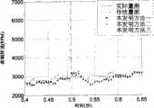
当杂讯于0.48秒加入曲轴转角感知器时,对于曲轴转角及转速估测结果的影响(如图8、图9所示)。首先图8中显示出曲轴转角的估测结果,其中传统量测在遇到一个强度较大的杂讯介入曲轴讯号时,其估测结果将发生错误。而本发明在有杂讯介入时,均能有效地减少杂讯对曲轴转角估测的影响。此外,当杂讯介入时,显示传统量测方法在估测转速时会产生约4000rpm的偏差,而本发明的估测偏差量约只有500rpm(如图9所示)。是以,本发明均能有效地减少杂讯对曲轴转角及转速估测的影响,故优于传统量测方法。When the noise is added to the crank angle sensor at 0.48 seconds, the impact on the crank angle and speed estimation results (as shown in Figure 8 and Figure 9). Firstly, Fig. 8 shows the estimation result of the crankshaft angle. When the traditional measurement encounters a strong noise intervening in the crankshaft signal, the estimation result will be wrong. However, the present invention can effectively reduce the influence of noise on crank angle estimation when noise is involved. In addition, when noise is involved, it shows that the traditional measurement method will produce a deviation of about 4000 rpm when estimating the rotational speed, while the estimation deviation of the present invention is only about 500 rpm (as shown in FIG. 9 ). Therefore, the present invention can effectively reduce the influence of noise on the crank angle and rotation speed estimation, so it is superior to the traditional measurement method.
Claims (7)
Priority Applications (1)
| Application Number | Priority Date | Filing Date | Title |
|---|---|---|---|
| CNB2006100805222ACN100497918C (en) | 2006-05-15 | 2006-05-15 | Method for estimating rotation angle and rotation speed of engine crankshaft |
Applications Claiming Priority (1)
| Application Number | Priority Date | Filing Date | Title |
|---|---|---|---|
| CNB2006100805222ACN100497918C (en) | 2006-05-15 | 2006-05-15 | Method for estimating rotation angle and rotation speed of engine crankshaft |
Publications (2)
| Publication Number | Publication Date |
|---|---|
| CN101074634A CN101074634A (en) | 2007-11-21 |
| CN100497918Ctrue CN100497918C (en) | 2009-06-10 |
Family
ID=38975868
Family Applications (1)
| Application Number | Title | Priority Date | Filing Date |
|---|---|---|---|
| CNB2006100805222AExpired - Fee RelatedCN100497918C (en) | 2006-05-15 | 2006-05-15 | Method for estimating rotation angle and rotation speed of engine crankshaft |
Country Status (1)
| Country | Link |
|---|---|
| CN (1) | CN100497918C (en) |
Families Citing this family (12)
| Publication number | Priority date | Publication date | Assignee | Title |
|---|---|---|---|---|
| US9845752B2 (en) | 2010-09-29 | 2017-12-19 | GM Global Technology Operations LLC | Systems and methods for determining crankshaft position based indicated mean effective pressure (IMEP) |
| CN102004037B (en)* | 2010-12-09 | 2013-06-26 | 联合汽车电子有限公司 | Self-learning method for rotating speed signal gear tooth deviation |
| US9127604B2 (en) | 2011-08-23 | 2015-09-08 | Richard Stephen Davis | Control system and method for preventing stochastic pre-ignition in an engine |
| US9097196B2 (en) | 2011-08-31 | 2015-08-04 | GM Global Technology Operations LLC | Stochastic pre-ignition detection systems and methods |
| US9133775B2 (en) | 2012-08-21 | 2015-09-15 | Brian E. Betz | Valvetrain fault indication systems and methods using engine misfire |
| US9121362B2 (en) | 2012-08-21 | 2015-09-01 | Brian E. Betz | Valvetrain fault indication systems and methods using knock sensing |
| US8973429B2 (en) | 2013-02-25 | 2015-03-10 | GM Global Technology Operations LLC | System and method for detecting stochastic pre-ignition |
| CN104747288B (en)* | 2013-12-26 | 2018-05-04 | 联创汽车电子有限公司 | Engine indication torque evaluation method and engine indication torque counting circuit |
| CN103940503A (en)* | 2014-04-15 | 2014-07-23 | 江苏大学 | Method for accurately diagnosing crankshaft damping change |
| JP2020033930A (en)* | 2018-08-29 | 2020-03-05 | トヨタ自動車株式会社 | Control device for internal combustion engine |
| CN111416564A (en)* | 2020-03-19 | 2020-07-14 | 深圳市微秒控制技术有限公司 | Data processing device and method for magnetic encoder |
| CN116122975A (en)* | 2022-12-29 | 2023-05-16 | 潍柴动力股份有限公司 | Method, device, equipment and storage medium for speed acquisition based on single-chip microcomputer |
Citations (5)
| Publication number | Priority date | Publication date | Assignee | Title |
|---|---|---|---|---|
| US5452604A (en)* | 1993-02-05 | 1995-09-26 | Mitsubishi Jidosha Kogyo Kabushiki Kaisha | Misfire detection method based on fluctuation in crankshaft rotation |
| JP2004245162A (en)* | 2003-02-14 | 2004-09-02 | Denso Corp | Internal combustion engine control device and method for processing crank angle signal of internal combustion engine |
| US20040182142A1 (en)* | 2001-10-19 | 2004-09-23 | Tomoji Nakamura | Engine crank angle detecting device |
| CN2706599Y (en)* | 2004-06-11 | 2005-06-29 | 李胥兵 | Crank phase identifier for four-stroke gasoline engine electro-controlling system |
| US20050160803A1 (en)* | 2002-09-30 | 2005-07-28 | Hitoshi Adachi | Device for discriminating engine crank angle |
- 2006
- 2006-05-15CNCNB2006100805222Apatent/CN100497918C/ennot_activeExpired - Fee Related
Patent Citations (5)
| Publication number | Priority date | Publication date | Assignee | Title |
|---|---|---|---|---|
| US5452604A (en)* | 1993-02-05 | 1995-09-26 | Mitsubishi Jidosha Kogyo Kabushiki Kaisha | Misfire detection method based on fluctuation in crankshaft rotation |
| US20040182142A1 (en)* | 2001-10-19 | 2004-09-23 | Tomoji Nakamura | Engine crank angle detecting device |
| US20050160803A1 (en)* | 2002-09-30 | 2005-07-28 | Hitoshi Adachi | Device for discriminating engine crank angle |
| JP2004245162A (en)* | 2003-02-14 | 2004-09-02 | Denso Corp | Internal combustion engine control device and method for processing crank angle signal of internal combustion engine |
| CN2706599Y (en)* | 2004-06-11 | 2005-06-29 | 李胥兵 | Crank phase identifier for four-stroke gasoline engine electro-controlling system |
Also Published As
| Publication number | Publication date |
|---|---|
| CN101074634A (en) | 2007-11-21 |
Similar Documents
| Publication | Publication Date | Title |
|---|---|---|
| CN100497918C (en) | Method for estimating rotation angle and rotation speed of engine crankshaft | |
| US7623955B1 (en) | Method for estimation of indicated mean effective pressure for individual cylinders from crankshaft acceleration | |
| JP4380604B2 (en) | Control device for internal combustion engine | |
| US10502659B2 (en) | Misfire detection device for internal combustion engine | |
| CN102062005B (en) | Method for calculating air intake flow and air intake pressure of engine | |
| CN102278223B (en) | Apparatus and method for estimating stopped engine crank angle | |
| US7194899B1 (en) | Method of estimating crack angles and rotation speeds of engine | |
| JP2015504134A5 (en) | ||
| CN109083756A (en) | A kind of engine charge fault detection method and device | |
| WO2008149832A8 (en) | Knocking determination device and knocking determination method for internal combustion engine | |
| CN103511109A (en) | Control apparatus for internal combustion engine | |
| CN107002578A (en) | Method and device for determining propulsion torque | |
| US10072595B2 (en) | Method and device for ascertaining a gas-mass flow in a combustion engine | |
| EP2530287A1 (en) | Apparatus and method for estimating a combustion torque of an internal combustion engine | |
| CN103256166A (en) | Knock control device of internal combustion engine | |
| US8849591B2 (en) | Method for processing a signal from a flow meter for measuring a gas flow in an internal combustion engine | |
| CN111868356A (en) | Method for checking variable valve lift control of an internal combustion engine | |
| JP2004184228A (en) | Knock detection device | |
| Jung et al. | A flywheel error compensation algorithm for engine misfire detection | |
| CN106414964A (en) | Control device for internal combustion engine | |
| CN100389302C (en) | Method of Predicting Engine Crankshaft Angle and Speed Value Using Kalman Filter | |
| CN105673234A (en) | Method and device for providing state parameters of filtering system in internal combustion engine controller | |
| JP2006343136A (en) | Water vapor partial pressure detection device, engine intake flow rate detection device, and collector internal pressure detection device | |
| CN108869075B (en) | Correction method and device for fuel injection advance angle of electronic control engine | |
| CN116480472B (en) | Supercharger rotation speed control method and device, electronic equipment and storage medium |
Legal Events
| Date | Code | Title | Description |
|---|---|---|---|
| C06 | Publication | ||
| PB01 | Publication | ||
| C10 | Entry into substantive examination | ||
| SE01 | Entry into force of request for substantive examination | ||
| C14 | Grant of patent or utility model | ||
| GR01 | Patent grant | ||
| ASS | Succession or assignment of patent right | Owner name:NATIONAL TAIPEI UNIVERSITY OF TECHNOLOGY Free format text:FORMER OWNER: CHEN BOQUAN Effective date:20090508 | |
| C41 | Transfer of patent application or patent right or utility model | ||
| TR01 | Transfer of patent right | Effective date of registration:20090508 Address after:Taipei City, Taiwan, China Patentee after:National Taipei University of Technology Address before:Taiwan, Taipei, China Co-patentee before:Wu Yuyi Patentee before:Chen Po-chuan Co-patentee before:Xie Fengji | |
| C17 | Cessation of patent right | ||
| CF01 | Termination of patent right due to non-payment of annual fee | Granted publication date:20090610 Termination date:20100515 |