CN100496425C - Plating system for fixation of bone segments - Google Patents
Plating system for fixation of bone segmentsDownload PDFInfo
- Publication number
- CN100496425C CN100496425CCNB038214628ACN03821462ACN100496425CCN 100496425 CCN100496425 CCN 100496425CCN B038214628 ACNB038214628 ACN B038214628ACN 03821462 ACN03821462 ACN 03821462ACN 100496425 CCN100496425 CCN 100496425C
- Authority
- CN
- China
- Prior art keywords
- plate
- locking member
- kit
- hole
- bone
- Prior art date
- Legal status (The legal status is an assumption and is not a legal conclusion. Google has not performed a legal analysis and makes no representation as to the accuracy of the status listed.)
- Expired - Fee Related
Links
Images


Landscapes
- Surgical Instruments (AREA)
- Prostheses (AREA)
Abstract
Translated fromChinese
Description
Translated fromChinese对相关申请的交叉参考:Cross-references to related applications:
本申请要求2002年7月16日提交的第60/396,251号临时申请的优先权。This application claims priority to Provisional Application No. 60/396,251, filed July 16,2002.
发明背景Background of the invention
多种类型的板装置和系统被用于固定包括脊柱在内的骨的部分结构。脊柱固定技术在脊柱节段的后面、前面、侧面、后侧面和前侧面部分应用板。这种板系统可在损伤的或发生病变的椎骨、椎间盘或脊柱的其它结构修复时提供固定作用。这种板系统可以单独或与其它移植物如其它板或固定系统或体内充填装置一起使用。Various types of plate devices and systems are used to immobilize portions of bony structures including the spine. Spinal fixation techniques apply plates to the posterior, anterior, lateral, posterior, and anterior portions of the spinal segment. This plate system provides immobilization during repair of damaged or diseased vertebrae, discs, or other structures of the spine. This plate system can be used alone or with other implants such as other plates or fixation systems or in vivo filling devices.
尽管脊柱板系统和其它骨固定系统是公知的,但仍需要进一步的改进。本发明与其它发明一样,目的是满足这一需要。Although spinal plate systems and other bone fixation systems are known, further improvements are desired. The present invention, like others, aims to fulfill this need.
发明概述Summary of the invention
本发明主要涉及用于固定一骨节段如脊柱节段的板系统。The present invention generally relates to plate systems for the fixation of a bony segment, such as a spinal segment.
用于将板固定于骨节段的骨螺钉可能由板脱出。本发明一个锁紧件的实施例可阻止螺钉脱出板并与被锁定的板和螺钉保持距离以使螺钉可在螺钉孔内枢转而不与锁紧件冲突。本发明另一个锁紧件实施例通过把骨螺钉头部啮合于板的上表面之下将骨螺钉相对固定于板,缩小位于骨节段之上的板系统的剖面。Bone screws used to secure the plate to the bone segment may come out of the plate. One embodiment of the locking member of the present invention prevents the screw from coming out of the plate and keeps the locked plate and screw at a distance so that the screw can pivot in the screw hole without conflicting with the locking member. Another locking member embodiment of the present invention reduces the profile of the plate system above the bone segment by engaging the head of the bone screw below the upper surface of the plate to secure the bone screw relative to the plate.
根据其它方面,用于固定骨节段的板系统包含一个至少接合于第一和第二骨成分的板。用于脊柱固定时,板至少连接于第一和第二个椎骨且每一个椎骨中至少有一个骨螺钉。一个选择的锁紧件连接于板以阻止该至少一个骨螺钉脱出板。一种锁紧件是一个可变的锁紧件允许该至少一个螺钉在板内栓牢而不与连接于板的锁紧件冲突。第二种锁紧件是一个固定的锁紧件当其连接于板时将该至少一个螺钉相对于板固定。According to other aspects, a plate system for securing a bone segment includes a plate engaged to at least first and second bone components. For spinal fixation, the plate is attached to at least the first and second vertebrae with at least one bone screw in each vertebrae. An optional locking member is coupled to the plate to prevent the at least one bone screw from dislodging from the plate. A locking member is a variable locking member that allows the at least one screw to be bolted within the panel without interfering with a locking member attached to the panel. The second type of locking member is a fixed locking member which secures the at least one screw relative to the board when connected to the board.
同时考虑了用于将板置入和连接于骨节段的器具和用于将锁紧件置入和连接于板的器具。A device for inserting and connecting a plate to a bone segment and a device for inserting and connecting a locking element to a plate are also contemplated.
进一步考虑了置入板和锁紧件的方法和脊柱固定的外科方法。The method of placing plates and locking elements and the surgical method of spinal fixation are further considered.
本发明还考虑一种用于固定骨节段的工具包。所述工具包可包括:一个具有贯穿其上表面和下表面的至少第一和第二孔的板;可置入所述第一和第二孔中的至少第一和第二骨紧固件;一个可连接到所述板毗邻其上表面的第一锁紧件,所述第一锁紧件具有贯通的排列在所述第一和第二孔上的孔口,其中,当所述第一锁紧件啮合所述板时,所述骨紧固件能栓牢在所述第一和第二孔中,同时所述锁紧件阻止所述骨紧固件脱出所述板的第一和第二孔;和一个连接到所述板毗邻其上表面的第二锁紧件,所述第二锁紧件的结构适合在所述第一和第二孔中啮合所述第一和第二骨紧固件以相对于所述板固定所述骨紧固件。The present invention also contemplates a kit for securing bone segments. The kit may include: a plate having at least first and second holes extending through its upper and lower surfaces; at least first and second bone fasteners insertable in the first and second holes a first locking member connectable to said plate adjacent its upper surface, said first locking member having apertures therethrough arranged on said first and second holes, wherein, when said first When a locking member engages the plate, the bone fastener can be bolted into the first and second apertures while the locking member prevents the bone fastener from coming out of the first hole of the plate. and a second hole; and a second locking member connected to said plate adjacent its upper surface, said second locking member being configured to engage said first and first holes in said first and second holes Two bone fasteners are used to secure the bone fasteners relative to the plate.
本发明更多的实施例、方面、形式、特点、优点、目的和原则也将在下面描述。Further embodiments, aspects, forms, features, advantages, objects and principles of the present invention will also be described below.
附图简述Brief description of the drawings
图1是包含本发明板系统的一部分的板的顶部平面图。Figure 1 is a top plan view of a panel comprising part of the panel system of the present invention.
图2是从线2-2看去的该板的剖视图-,毗邻一个骨节段放置。Figure 2 is a cross-sectional view of the plate as seen from line 2-2 - placed adjacent to a bone segment.
图3是从线3-3看去的该板的剖视图-。Figure 3 is a cross-sectional view of the plate as seen from line 3-3-.
图4是包含本发明板系统的一部分的第一锁紧件实施例的顶部平面图。Figure 4 is a top plan view of a first locking member embodiment comprising part of the plate system of the present invention.
图5是图4中锁紧件的底部平面图。Fig. 5 is a bottom plan view of the locking member of Fig. 4 .
图6是从图5中的线6-6看去的该锁紧件的剖视图-。Fig. 6 is a cross-sectional view of the locking member - seen from line 6-6 in Fig. 5 .
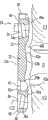
图7是图1中板的侧面立视图,骨紧固件使图4中的第一锁紧件沿着该板的上表面部分连接到板。7 is a side elevational view of the plate of FIG. 1 with bone fasteners connecting the first locking member of FIG. 4 to the plate along its upper surface portion.
图8是包含本发明板系统的一部分的第二锁紧件实施例的顶部平面图。Figure 8 is a top plan view of a second locking member embodiment comprising part of the plate system of the present invention.
图9是图8中的锁紧件的底部平面图。FIG. 9 is a bottom plan view of the locking member of FIG. 8 .
图10是图8中的锁紧件的侧面立视图。Figure 10 is a side elevational view of the locking member of Figure 8 .
图11是从图8中的线11-11看去的该锁紧件的剖视图-。FIG. 11 is a cross-sectional view of the locking member seen from line 11-11 in FIG. 8-.
图12是从图9中的线12-12看去的图8中锁紧件的剖视图-。FIG. 12 is a cross-sectional view of the locking member of FIG. 8 viewed from line 12 - 12 in FIG. 9 - .
图13是带有骨紧固件的图1中的板的剖视图,以及毗邻该板上表面放置并接合于那里的从图9中的线13-13看去的第二锁紧件实例的剖视图-。13 is a cross-sectional view of the plate of FIG. 1 with bone fasteners, and a cross-sectional view of an example of a second locking member, viewed from line 13-13 of FIG. 9, positioned adjacent to the upper surface of the plate and engaged therein -.
图14是用于将板和锁紧件置入手术部位的器具的透视图。Figure 14 is a perspective view of an instrument for placing the plate and locking member into the surgical site.
图15是连接于图4中锁紧件的图14中的器具的远端放大透视图。15 is an enlarged perspective view of the distal end of the implement of FIG. 14 coupled to the locking member of FIG. 4 .
图16是位于板之上的引导装置的透视图,该引导装置用于引导紧固件孔的钻孔、穿刺和/或紧固件的插入以将板固定于骨节段。16 is a perspective view of a guide positioned over a plate for guiding drilling of fastener holes, piercing, and/or insertion of fasteners to secure the plate to a bone segment.
具体实施方案详述Detailed description of the specific implementation plan
为了加深对本发明的原理的理解,将参考附图中阐明的实施方案,相同的部分将用特定的语言描述。无论如何都应明确并不由此意味对本发明范围的限制。所阐明装置的任何类似改变和改进以及所描述的本发明原理的任何类似应用已被设想,正如本发明领域的技术人员通常会做的。In order to deepen the understanding of the principles of the invention, reference will be made to the embodiments illustrated in the drawings, and like parts will be described in specific language. In any event, no limitation of the scope of the invention is intended thereby. Any similar changes and modifications of the illustrated devices and any similar applications of the principles of the invention described are contemplated as would normally occur to those skilled in the art of the invention.
本发明包含一个用于连接于人体一骨节段的板。提供锁紧件以防止板紧固件相对于板脱出。紧固件将板连接于第一和第二骨节段以使这些骨节段相对稳定。在一个实施方案中,板连接于脊柱的第一和第二椎骨。在另一个实施方案中,板可连接于脊柱胸椎或腰椎的侧面或斜面。与脊柱的其它椎体以及椎体的其它方向的连接也被设想。The invention comprises a plate for attachment to a bone segment of a human body. A lock is provided to prevent disengagement of the panel fastener relative to the panel. Fasteners connect the plate to the first and second bone segments to relatively stabilize the bone segments. In one embodiment, the plates are attached to the first and second vertebrae of the spine. In another embodiment, the plates may be attached to the sides or slopes of the thoracic or lumbar spine. Connections to other vertebral bodies of the spine and other orientations of the vertebral bodies are also contemplated.
该板通过至少一个邻近板每一端的固定螺钉固定于每一骨节段。在一个特殊实施方案中,板包含一个沿上椎骨放置的第一部分、一个沿下椎骨放置的第二部分和其间沿着两毗邻脊椎之间的椎间盘空间延伸的中间部分。第一部分包含一对容纳骨紧固件以将板啮合于上椎骨的孔,第二部分包含一对容纳骨紧固件以将板啮合于下椎骨的孔。The plate is secured to each bone segment by at least one set screw adjacent each end of the plate. In a particular embodiment, the plate comprises a first portion positioned along the upper vertebra, a second portion positioned along the lower vertebra, and an intermediate portion extending therebetween along the intervertebral disc space between two adjacent vertebrae. The first portion includes a pair of holes that receive bone fasteners to engage the plate to the upper vertebrae, and the second portion includes a pair of holes that receive bone fasteners to engage the plate to the lower vertebrae.
所述板系统带有锁紧件,一旦固定于其位置啮合板和骨节段可防止骨紧固件脱出板。在一个实施方案中,锁紧件为一可变锁紧件。可变锁紧件至少部分延伸于螺钉孔之上阻止螺钉脱出板。可变锁紧件设计为包含孔口或孔,穿过此处放置固定板于骨节段的骨紧固件。所述孔口小于骨紧固件的上方部分,然而允许骨紧固件在板孔内枢转而不与可变锁紧件冲突。在另一个实施方案中提供一个固定锁紧件,包含对应于板内骨紧固件的位置伸出的凸出部分。该凸出部分啮合骨紧固件的上方部分,阻止骨紧固件脱出板和相对于板枢转。The plate system has locking elements that engage the plate and bone segments once secured in position to prevent the bone fasteners from coming out of the plate. In one embodiment, the locking member is a variable locking member. The variable locking member extends at least partially over the screw hole to prevent the screw from coming out of the plate. The variable locking member is designed to include an aperture or hole through which the bone fastener that fixes the plate to the bone segment is placed. The aperture is smaller than the upper portion of the bone fastener, yet allows the bone fastener to pivot within the plate hole without conflicting with the variable lock. In another embodiment there is provided a fixation lock comprising a protrusion protruding corresponding to the position of the bone fastener within the plate. The protrusion engages the superior portion of the bone fastener, preventing the bone fastener from dislodging and pivoting relative to the plate.
参考图1-3,显示板20连接于骨节段。板20包含具有上表面22a和相对的下表面22b的主体22。主体22包含第一侧面24和第二侧面26。第一侧面24和第二侧面26在第一末端28和相对的第二末端30之间延伸。第一和第二侧面24、26可具有凹入形状以最小化主体22沿着骨节段的横向宽度。第一末端28和第二末端30可相对于板的纵轴L呈倾斜状,这样第二侧面26具有大于第一侧面24的长度,主体22过渡于侧面24、26和末端26、30之间的角可呈圆形以消除可能刺入、割伤或磨破组织的锐利或突兀的边缘。主体22上表面22a和下表面22b之间的过渡表面也可被制成光滑和圆形表面以消除可能刺入、割伤或磨破组织的锐利或突兀的边缘。Referring to Figures 1-3, a
板20的主体22还包含第一部分48、第二部分50和延伸于其间的中间部分52。板20包含毗邻第一末端28位于第一部分48内延伸穿过主体22的第一孔32和第二孔34。板20还包含毗邻第二末端30位于第二部分50内延伸穿过主体22的第三孔36和第四孔38。孔32、34、36和38开口于上表面22a和下表面22b并在其间延伸。其它实施方案设想第一和第二部分48、50之一或全部具有单一的孔。还有的实施方案设想第一和第二部分48、50之一或全部具有两个以上的孔。The
在所例举的图2的实施方案中,板20可紧贴并连接于脊柱节段的脊椎V1和V2。考虑到板20的全部结构可被标准化并在一定的尺寸范围内被提供,外部尺寸也可根据由标准化测量或待固定部位的手术前建模确定的患者的解剖学而变化。板20可具有适合连接于脊柱胸段或腰段的第一和第二脊椎的形状。然而,只要板可连接于脊柱或其它骨节段,也可设想其它形状。In the illustrated embodiment of FIG. 2 ,
主体22的下表面直接面向骨节段。在图解实施方案中,下表面22b适合沿脊椎V1和V2放置。下表面22b包含沿着第一部分48的第一表面部分48a、沿着第二部分50的第二表面部分50a、和沿着中间部分52的中间表面部分52a。第一和第二表面48a、50a可具有一过渡表面48b、50b,两过渡表面均包含一沿纵轴L的凸面弯曲部分。该凸面弯曲部分过渡进入延伸至中间表面部分52a的凹面弯曲部分内。这些凹面-凸面弯曲的过渡表面允许主体22嵌套贴紧毗邻相应的脊椎终板的脊椎V1和V2的侧面和斜面。The lower surface of the
沿着脊椎V1和V2之间的椎间盘空间放置的中间表面部分52a,可为沿纵轴L的凸面弯曲。主体22的上表面22a和下表面22b通常可具有横过或关于纵轴L的非曲线形结构。其它实施方案中为板20设计了其它适合于将要固定板20的解剖位置的上表面22a和下表面22b结构。The
参考图2,详述了板孔沿纵轴L的定位。孔32和34可以各有一个如图2中孔34的中心线C1所示的中心线,相对于上表面22a朝向第一末端28成大约6度的角度。孔36和38可以各有一个如图2中孔38的中心线C2所示的中心线,相对于上表面22a朝向第二末端30成大约6度的角度。在这个图解实施方案中,其中板20被连接至脊柱节段,孔32、34的中心线定位于头侧,孔36、38的中心线定位于尾侧。Referring to Figure 2, the positioning of the plate holes along the longitudinal axis L is detailed. Apertures 32 and 34 may each have a centerline, shown as centerline C1 of
参考图3,详述了板孔关于纵轴L的定位。毗邻的孔对32、34和毗邻的孔对36、38可以有在板20的下表面22b以下会聚的中心线。例如,孔36的中心线C2和孔38的中心线C3的方向分别相对于轴A呈角度B2和B3。轴A位于中心部并在上表面22a和下表面22b间正交穿过板29的纵轴L延伸。在一个实施方案中,角度B2和B3各为大约6度。其它实施方案中设计的紧固孔32、34、36和38的中心线相互之间及与板20之间的方向不同于上述实施方案。例如,毗邻孔对的中心线可以在板下发散。在另一实施例中,孔的中心线可以正交于板的上表面和下表面之一或两者。Referring to FIG. 3 , the positioning of the plate holes with respect to the longitudinal axis L is detailed. Adjacent pairs of
孔32、34、36和38具有与板20的上表面22a相联系的球形座。例如,孔34的座34a和孔36的座36a具有一个与放置其中的骨紧固件头部之下相应形状的表面相匹配的球形部分。以此方式,骨紧固件能够采用多个相对于孔的相应中心线的角度在相应孔中栓牢。在一个实施方案中,该角度活动的范围关于相应轴在所有方向上从0度到大约6度变化。还设想孔32、34、36和38中的座的位置低于主体22的上表面22a,以使放置其中的骨紧固件在与紧固件孔中的座接触时,其头部或上部凹进上表面22a的下面。
第一孔32可以朝向第一末端28的方向偏离第二孔34,第三孔36可以朝向第二末端30的方向偏离第四孔34。螺钉孔对间的偏离允许上方部分48内毗邻孔对的每个孔32、34和下方部分50内毗邻孔对的每个孔36、38的位置都靠近纵轴L。以此方式,在保持主体22空对间结构的完整性的同时可使板20的主体22的横向宽度最小化。The
板20包含一个毗邻第一和第二孔32、34由上表面22a延伸穿过第一部分48的第一钻孔40。板20还有一个毗邻第三和第四孔36、38由上表面22a延伸穿过第二部分50的第二钻孔40。钻孔40、42延伸穿过板20或达一足够距离以容纳一个紧固件的一部分,以使锁紧件啮合于板20,如下面进一步讨论的。如图2所示,参考钻孔42,钻孔40、42均可具有毗邻上表面22a的扩大的部分42a,并具有带有螺纹或被塑型的下方部分以啮合锁紧件紧固件90。扩大部分42a允许紧固件90在与螺纹部分42b咬合前位于钻孔42中心并恰当放置。
板20包含一位于主体22中心开口于上表面22a的凹槽44。凹槽44可具有螺纹或被塑型以啮合用于将板20放置在毗邻骨节段的置入器具。毗邻或侧向偏离凹槽44有一毗邻校准凹槽46。设想凹槽44、46可以完全延伸穿过板20或至少在其中延伸足够远以足够容纳置入工具,如下面进一步讨论的。板的其它实施方案设想将板20放置在毗邻骨节段的其它方法。例如,可以使用一个抓住板20的侧边和/或末端的,或啮合于钻孔40、44或孔32、34、36、36其中之一或更多的置入工具。The
现参考图4-6,显示了一个可如图7所示连接于板20的第一锁紧件实例60。锁紧件60包含一分别由第一和第二凹面侧边64和66以及相对的第一和第二末端68和70界定的主体62。第一和第二末端68、70可以相对于锁紧件60的纵轴L倾斜。锁紧件60的尺寸和形状可以与板20的尺寸和形状相对应。锁紧件60的其它实施方案可以设想与板20不同的尺寸和形状。Referring now to FIGS. 4-6, an example of a
锁紧件60包含一对毗邻的第一和第二孔口72和74,和一对毗邻的第三和第四孔口76和78。当锁紧件60固定于板上时孔口72、74、76和78各自对准板20的孔32、34、36和38。根据板20的骨紧固件孔的数目和锁紧件60是否具有与板20的骨固定件孔相同数目的孔口,锁紧件60可具有更多或更少的孔口。锁紧件60还包含一毗邻第一和第二孔口72、74的第一穿通孔80,和毗邻第三和第四孔口76、78的第二穿通孔82。穿通孔80和82可各自具有扩大的上方部分80a、82a以使锁定紧固件90的头部凹进并提供沿着锁紧件60的上表面62a的低剖面。穿通孔80、82也可以具有扩大的下方部分80b、82b和上下两部分间的螺纹形式以使锁定紧固件穿过相应的穿通孔螺纹式插入。Locking
锁紧件的上表面62a可以具有沿着纵轴L1的轻微凸面曲率。下表面62a可以是平直的以紧贴板20平直的上表面放置。锁紧件60在上表面62a和下表面62b之间具有足够的厚度足以抵抗加在锁紧件60上的负荷所产生的弯曲和其它形变,然而应在板20上方产生尽可能低的剖面。The
锁紧件60的上表面62a内还包含一个凹入表面88。凹入表面88是平直的并为置入器具提供连接位置。一个中心凹槽84和一个毗邻的校准凹槽86延伸于上表面62a和下表面62b之间。凹槽84、86为锁紧件与置入器具的连接和校准提供位置,如下面进一步讨论的。中心凹槽84可以是螺纹状以利于锁紧件60与置入器具的连接。校准凹槽86可以是倾斜地毗邻上表面62a以利于置入器具的校准元件的插入。The
如图7所示,骨紧固件92将板20的主体22连接至骨节段。骨紧固件92可以是网眼状骨螺钉。还设想板20可以与任何类型的骨啮合紧固件连接,例如锚或螺栓。骨紧固件92的头部的下方92b可以是圆形的,位于螺钉容纳于孔32、34、36和38内的光滑的柄部之上。圆形的头92b允许所述紧固件恰当地安放于板20内围绕孔32、34、36和38形成的座内,这样在螺钉安放过程中或之后可使所述紧固件相对于板20改变角度或栓牢。锁紧件60通过一个或更多锁定紧固件90连接于板20。在图解实施方案中,锁定紧固件90为具有一杆部和一扩大的头部的固定螺钉,所述杆部螺纹式啮合于板20的钻孔40、42中相应一个之内,所述扩大的头部位于锁紧件60的穿通孔80、82的扩大的上方部分80a、82a之内。As shown in FIG. 7,
锁紧件60通过锁定紧固件连接于板20时,孔口72、74、76和78位于板20的孔32、34、36和38中相应的一个之上。孔口72、74、76、78防止孔32、34、36、38中每一孔内的每个骨紧固件92的头部92b在栓牢时接触锁紧件60,这样可允许骨紧固件92全部范围的成角运动。孔口72、74、76、78中每一个均可包含一有斜面的下方部分,例如图6所示孔口72、76的斜面部分72a、76a,以提供与紧固件92的头部92b的上表面92c之间更大的距离。然而,孔口72、74、76和78小于骨紧固件92的头部,因此,如果一个骨紧固件92脱出其板20内的座,锁紧件60的主体62将接触螺钉头以阻止更多的脱出并栓牢。设计为在锁紧件60安装后上紧骨紧固件92而不需移动锁紧件60的每一骨紧固件92的头部92b内的工具啮合凹槽92a仍能通过孔口72、74、76、78进入。The
现参考图8-13进一步详述另一个锁紧件实施方案100。锁紧件100具有适合安装于板20的一般形状和尺寸,如上面锁紧件60中讨论的。锁紧件100包含一个具有第一和第二凹面侧边104和106的主体102和倾斜的第一末端108和第二末端110。这样锁紧件100的尺寸和形状对应于板20的尺寸和形状。还设想锁紧件100可以具有与板20不同的尺寸和形状。Another locking
锁紧件100的主体102包含一上表面102a和一下表面102b。锁紧件100还包含由主体102的下表面102b延伸的一对毗邻的第一和第二啮合元件112和114以及一对毗邻的第三和第四啮合元件116和118。当锁紧件100固定于板20时,啮合元件112、114、116、118各自对准板20的孔32、34、36、38。锁紧件100还包含一毗邻第一和第二啮合元件112、114的第一穿通孔120和一毗邻第三和第四啮合元件116、118的第二穿通孔122。穿通孔120和122可各自具有扩大的上面部分120a、122b,以使锁定紧固件90沿锁紧件100的上表面102a具有低剖面。穿通孔120、122还可具有中间螺纹形式以使锁定件由此螺纹式插入。The
锁紧件100的上表面102a沿纵轴L2有一轻微的凸面曲率。下表面102b是平直的并紧贴板20的上表面22a放置。锁紧件100在上表面102a和下表面102b之间具有足够的厚度足以抵抗加在锁紧件100上的负荷所产生的弯曲和其它形变,然而仍在板20上方具有尽可能低的剖面。主体102在其下表面102b内具有第一槽130和第二槽132以使主体102具有一些灵活性,在必要时允许锁定件90促使啮合元件112、114、116、118与骨紧固件92的头部的啮合。The
锁紧件100还在上表面102a内包含一凹入的表面128。凹入的表面128是平直的并为置入器具提供连接位置。一个中心凹槽124和一毗邻的校准凹槽126在上表面102a和下表面102b之间延伸。凹槽124、126象锁紧件60的凹槽一样为置入器具与锁紧件100的连接和校准提供位置。The locking
在图12中就啮合元件112提供啮合元件112、114、116和118的更多细节。啮合元件112包含一可放置在骨紧固件92的工具啮合凹槽92a内的中心凸起112a,如图13所示。一凹槽112b围绕中心凸起元件112a延伸,凹槽112b的尺寸适合容纳骨紧固件92的头部92b的上表面92c。中心凸起112a的尺寸适合在工具啮合凹槽92a内啮合骨紧固件92,这样工具啮合凹槽92a的边接触中心凸起112a,相对于板20固定骨紧固件。Further details of
啮合元件112的侧壁112c以一定角度逐渐变低,这样啮合元件112中间的边自下表面102b延伸一段距离d2,啮合元件112外侧的边自下表面102b延伸一段距离d1。以这种方式,啮合元件112与主体102的底面102b的角度与骨紧固件92的头部穿过板20的角度相对应。这允许中心凸起112a牢固地安放于骨紧固件92的工具啮合凹槽92a内。啮合元件114、116和118可以类似地均包含一个中心凸起和围绕它的凹槽并具有逐渐变低的侧壁以啮合骨紧固件92的头部。The side walls 112c of the
骨螺钉引导装置可被用于引导骨螺钉穿过板孔放置以使骨螺钉的头部相对于板恰当成角以啮合啮合元件112、114、116和118。当骨螺钉的头部被锁紧件100啮合,骨螺钉相对于板20被固定。啮合元件112、114、116和118被容纳于毗邻的板孔,这样锁紧件100可以齐平地紧贴板20的上表面放置,阻止组织进入锁紧件100和板20的上表面之间,并最大程度缩小延伸于骨节段之上的结构的总剖面。如图13所示,锁紧件100在板20的上表面之上延伸并具有为锁紧件100提供足够硬度的厚度以抵抗弯曲力并保证骨螺钉确切的固定以防止它们脱出啮合的脊椎。A bone screw guide can be used to guide bone screw placement through the plate hole so that the head of the bone screw is properly angled relative to the plate to engage the
图14中显示了用于将板20置入到外科部位和用于将锁紧件60、100连接到置入的板20的置入器具150。图15中,表示了被锁接在置入器具150末端的锁紧件60,可以推定,锁紧件100及板20也可连接到装置150末端。置入器具150将锁紧件60、100对齐放置在板20上,从而当锁紧件60、100连接到那里时防止其相对于板20的转动。An
置入器具150包括一个近端手柄连接端152和一个从近端152向远端延伸的轴154。轴154与近端152间形成一个角度,以使连接在近端152的手柄的位置远离外科医生进入手术部位的入路。远端的脚156从轴154的远端以一个通常合适的角度延伸至那里。脚156包括一个由此伸向远端的校准元件158和一个毗邻的连接元件160。连接元件160包括一个头部162、一个中间螺纹部分164和一个远端无螺纹部分166。
置入器具150可分离地连接于板20以在板20与骨节段啮合之前或期间放置和控制板20。中间部分164螺纹啮合中心凹槽44、校准元件158容纳于校准凹槽46中以确保和保持板20与置入器具150的正确对接。
置入器具150还可分离地连接于锁紧件60、100用于将选择的锁紧件放置并啮合于板20。连接件160的中间部分164螺纹啮合锁紧件60的中心凹槽84或锁紧件100的中心凹槽124。校准件158被容纳在相应的校准凹槽86、126中,以确保和保持所选择锁紧件60、100与置入器具150的正确对接。脚156沿表面88、128放置并在此用轴承啮合。当选择的锁紧件60、100连接至板20,校准件158被容纳在校准凹槽46中且远端部分166被容纳在中心凹槽44中。中间部分164可螺纹啮合中心凹槽44以临时将选择的锁紧件60、100锁接于板20上。校准件158协助防止选择的锁紧件60、100在通过锁定件90连接期间相对于板20移动。锁定件90放置在相应的锁紧件60的穿通孔80、82中或锁紧件100的穿通孔120、122中,以将锁紧件啮合到板20。此后置入器具150从板20脱离并从固定的锁紧件60、100脱离。The
可以理解,这里描述的器具150的设计的许多变化是可以设想的。例如,用于连接和分离板20的装置可以与板20的凹槽44扣接/去扣接,或向周围延伸,或抓住一个或多个板20和/或锁紧件60、100的边沿。It is understood that many variations in the design of the
现参考图16,显示了用于引导钻头、丝锥和/或骨紧固件穿过板20的孔的引导装置的实施方案。图16中,板20通过连接元件160连接到置入器具150。引导装置200包含一个可紧贴板20放置的基板202。基板202包含一个大小适合容纳连接元件160的凹槽216;并且基板202的底表面可包括一个凹槽以容纳脚156,以使基板202能平直放置于板202的上表面22a。基板202还包含一个用于容纳贯穿其中的紧固件218的开口。紧固件218啮合在脚156中的孔157中,以将引导装置200固定到置入器具154。Referring now to FIG. 16 , an embodiment of a guiding device for guiding drill bits, taps and/or bone fasteners through the holes of
引导装置200包含于一个位于第一末端的第一引导件204和位于相对末端的第二引导件210。第一引导件204包含与板20的孔32对准的第一入口206,和与板20的孔34对准的第二入口208。第二引导件210包括与板20的孔36对准的第一入口212,和与板20的孔38对准的第二入口214。入口206、208、212、214提供伸长的通道,该通道容纳和引导钻孔、锥入和置入器具,从而为骨啮合紧固件在它们相应的板孔中提供理想的方向。The
用于将板20连接到骨节段的外科方法的例子之一包括将板20连接到置入器具,例如上面讨论的器具150的远端。板20以理想的方位和位置被放置在毗邻骨节段之上。当使用置入器具150放置板20时,在取走置入器具150之前,理想的锁紧件60、100不能被固定在板20上。钻头导引,譬如钻头导引200可用于为穿过板20钻的和/或刻螺纹的紧固件孔和/或为紧固件相对于板20的插入提供理想的方向。然后,骨紧固件92被螺丝起子或类似的方法上紧以将板20固定于骨节段。骨紧固件92的穿孔部位和穿入角度的值的最佳选择可在操作期间或之前由外科医生确定和调整。板固定到骨节段后,置入器具150从板20撤走,然后连接到理想的锁紧件60、100,以将理想的锁紧件啮合至板20。One example of a surgical method for attaching
设想这里描述的板可以和一个或多个锁紧件、用于植入板和锁紧件的器具、和用于制成穿通板至骨节段内的孔及紧固件插入的引导装置一起提供在一个工具包中。例如,可与板20同时提供必备的骨螺钉和置入器具,例如器具150,以及钻头导引装置,例如钻头导轨200。可以提供每个紧固件实施例60、100以使外科医生方便地选择用于将板20固定到骨节段的理想工具。It is contemplated that the plates described herein may be provided with one or more locks, tools for implanting the plates and locks, and guides for making holes through the plate into bone segments and insertion of the fasteners in one kit. For example, the requisite bone screws and insertion instruments, such as
例如,当固定到板20时,锁紧件60和骨紧固件92允许骨紧固件在骨节段上或在一个或更多移植物、移植片或骨节段相邻部分间的其它装置上枢转和在上述骨节段或装置上保持压力。锁紧件100和骨紧固件92固定于板20时相对于板20固定骨紧固件,所述板20保持骨节段相邻部分之间的空间。其它实施例设想一个结合了锁紧件60和锁紧件100的元件的锁紧件。例如,一端可具有孔或其它结构以允许紧固件栓牢于板,另一端具有啮合元件以啮合紧固件使其相对于板固定。其它实施例设想锁紧件包含两个或更多可啮合于板的元件。例如,该锁紧件的第一锁紧元件可以啮合于板的第一部分,该锁紧件的第二锁紧元件可以啮合于板的第二部分。For example, when secured to plate 20, locking
本发明设想了多种用于固定锁紧件于板上的紧固件,例如夹子、固定螺钉、锁定紧固件、和钉子。还设想锁紧件可以是可滑动地或可转动地啮合于板并在其上预加负荷。本发明还设想锁紧件被一个适合于板的阻碍物或其它附加元件固定于板。The present invention contemplates a variety of fasteners for securing the locking member to the panel, such as clips, set screws, locking fasteners, and nails. It is also contemplated that the locking member may be slidably or rotatably engaged and preloaded with the plate. The present invention also contemplates that the locking member is secured to the panel by a barrier or other additional element adapted to the panel.
可用于制造板和锁紧件的材料包含任何生物相容的非吸收性材料,如钛、不锈钢、形状记忆合金或它们的结合。也设想使用吸收性材料。锁紧件、板和紧固件可由相同材料或不同材料制成。板组件也可与各种形式的移植物一起使用。例如,在脊柱外科这样的移植物包括体内隔板、填充装置、和放置于椎间盘空间D的骨移植物材料。更多这种装置的例子包括骨销、推进式支撑架、旋入式支撑架、锥形支撑架、填充骨移植物和/或移植物替代材料或其它类型适合这种融合应用的装置的支撑架、脊柱节段或其它骨节段的外部或内部的固定器。Materials that can be used to make the plates and locks include any biocompatible non-absorbable material such as titanium, stainless steel, shape memory alloys, or combinations thereof. The use of absorbent materials is also contemplated. Locks, plates and fasteners can be made of the same material or different materials. Plate assemblies can also be used with various forms of grafts. For example, in spinal surgery such implants include internal spacers, filling devices, and bone graft material placed in the intervertebral disc space D. Further examples of such devices include bone pins, push-on scaffolds, screw-in scaffolds, tapered scaffolds, filled bone grafts and/or graft substitute materials or other types of supports suitable for this fusion application An external or internal fixator for a frame, spinal segment, or other bony segment.
虽然已经在附图和前面的描述中详细例证并描述了本发明,但与例证相同的也可被考虑到并且不受特征的限制,可以理解,只有优选的实施方案被显示和描述,并且所有在本发明宗旨范围内的变化和改良都要求受到保护。While the invention has been illustrated and described in detail in the drawings and foregoing description, it being considered that the same is illustrated and not limited in character, it is to be understood that only the preferred embodiment has been shown and described, and that all Changes and improvements within the scope of the spirit of the invention are claimed.
Claims (21)
Translated fromChineseApplications Claiming Priority (3)
| Application Number | Priority Date | Filing Date | Title |
|---|---|---|---|
| US39625102P | 2002-07-16 | 2002-07-16 | |
| US60/396,251 | 2002-07-16 | ||
| US10/219,516 | 2002-08-15 |
Publications (2)
| Publication Number | Publication Date |
|---|---|
| CN1691919A CN1691919A (en) | 2005-11-02 |
| CN100496425Ctrue CN100496425C (en) | 2009-06-10 |
Family
ID=35346914
Family Applications (1)
| Application Number | Title | Priority Date | Filing Date |
|---|---|---|---|
| CNB038214628AExpired - Fee RelatedCN100496425C (en) | 2002-07-16 | 2003-07-14 | Plating system for fixation of bone segments |
Country Status (1)
| Country | Link |
|---|---|
| CN (1) | CN100496425C (en) |
Families Citing this family (4)
| Publication number | Priority date | Publication date | Assignee | Title |
|---|---|---|---|---|
| US7771433B2 (en)* | 2004-12-14 | 2010-08-10 | Depuy Products, Inc. | Bone fracture fixation plate shaping system |
| TWI584776B (en)* | 2014-06-13 | 2017-06-01 | Cheng-Xin She | A fixed bone plate |
| CN105030319A (en)* | 2015-08-24 | 2015-11-11 | 苏州市康力骨科器械有限公司 | Fixing structure of multidirectional locking steel plate for proximal femur |
| CN109833086A (en)* | 2019-02-01 | 2019-06-04 | 南方医科大学南方医院 | A kind of steel plate rebuild for Periprosthetic fracture |
Citations (5)
| Publication number | Priority date | Publication date | Assignee | Title |
|---|---|---|---|---|
| US4794918A (en)* | 1985-05-06 | 1989-01-03 | Dietmar Wolter | Bone plate arrangement |
| US5879389A (en)* | 1995-04-07 | 1999-03-09 | Koshino; Tomihisa | Medical substituting element for hard tissues and artificial joint |
| US6261291B1 (en)* | 1999-07-08 | 2001-07-17 | David J. Talaber | Orthopedic implant assembly |
| EP1169971A2 (en)* | 2000-06-26 | 2002-01-09 | Stryker Spine SA | Bone screw retaining system |
| CN2551206Y (en)* | 2002-06-28 | 2003-05-21 | 中国人民解放军第二军医大学 | Self-locking point-contacting internal fixing system for anterior cervical region |
- 2003
- 2003-07-14CNCNB038214628Apatent/CN100496425C/ennot_activeExpired - Fee Related
Patent Citations (5)
| Publication number | Priority date | Publication date | Assignee | Title |
|---|---|---|---|---|
| US4794918A (en)* | 1985-05-06 | 1989-01-03 | Dietmar Wolter | Bone plate arrangement |
| US5879389A (en)* | 1995-04-07 | 1999-03-09 | Koshino; Tomihisa | Medical substituting element for hard tissues and artificial joint |
| US6261291B1 (en)* | 1999-07-08 | 2001-07-17 | David J. Talaber | Orthopedic implant assembly |
| EP1169971A2 (en)* | 2000-06-26 | 2002-01-09 | Stryker Spine SA | Bone screw retaining system |
| CN2551206Y (en)* | 2002-06-28 | 2003-05-21 | 中国人民解放军第二军医大学 | Self-locking point-contacting internal fixing system for anterior cervical region |
Also Published As
| Publication number | Publication date |
|---|---|
| CN1691919A (en) | 2005-11-02 |
Similar Documents
| Publication | Publication Date | Title |
|---|---|---|
| AU2003254044B2 (en) | Plating system for stabilizing a bony segment | |
| US9968382B2 (en) | Spinal stabilization system and method | |
| US6692503B2 (en) | System and method for securing a plate to the spinal column | |
| US8317845B2 (en) | Screw and method of use | |
| AU2004208819B2 (en) | Midline occipital vertebral fixation system | |
| US8470007B2 (en) | Antero-lateral plating systems and methods for spinal stabilization | |
| JP3537436B2 (en) | A device to fix the spine from the front | |
| US20040039387A1 (en) | System for stabilizing a portion of the spine | |
| KR20100101087A (en) | Periprosthetic fracture repair | |
| JPH06285082A (en) | Fixing device | |
| CN100496425C (en) | Plating system for fixation of bone segments | |
| KR20050023434A (en) | Plating system for stabilizing a bony segment | |
| AU2002322554A1 (en) | Spinal stabilization system and method | |
| MXPA06011248A (en) | Cervical intervertebral prosthesis |
Legal Events
| Date | Code | Title | Description |
|---|---|---|---|
| C06 | Publication | ||
| PB01 | Publication | ||
| C10 | Entry into substantive examination | ||
| SE01 | Entry into force of request for substantive examination | ||
| ASS | Succession or assignment of patent right | Owner name:WARSAW ORTHOPEDICS INC. Free format text:FORMER OWNER: SDGI HOLDINGS, INC. Effective date:20061215 | |
| C41 | Transfer of patent application or patent right or utility model | ||
| TA01 | Transfer of patent application right | Effective date of registration:20061215 Address after:indiana Applicant after:Warsaw Orthopedic Inc. Address before:Delaware Applicant before:SDGI Holding, Inc. | |
| C14 | Grant of patent or utility model | ||
| GR01 | Patent grant | ||
| C17 | Cessation of patent right | ||
| CF01 | Termination of patent right due to non-payment of annual fee | Granted publication date:20090610 Termination date:20100714 |