CN100496355C - Extraction assembly with linear sealing unit for the preparation under pressure of a drink from a cartridge - Google Patents
Extraction assembly with linear sealing unit for the preparation under pressure of a drink from a cartridgeDownload PDFInfo
- Publication number
- CN100496355C CN100496355CCNB200480003653XACN200480003653ACN100496355CCN 100496355 CCN100496355 CCN 100496355CCN B200480003653X ACNB200480003653X ACN B200480003653XACN 200480003653 ACN200480003653 ACN 200480003653ACN 100496355 CCN100496355 CCN 100496355C
- Authority
- CN
- China
- Prior art keywords
- capsule
- component
- sub
- extraction
- assembly according
- Prior art date
- Legal status (The legal status is an assumption and is not a legal conclusion. Google has not performed a legal analysis and makes no representation as to the accuracy of the status listed.)
- Expired - Fee Related
Links
Images


Classifications
- A—HUMAN NECESSITIES
- A47—FURNITURE; DOMESTIC ARTICLES OR APPLIANCES; COFFEE MILLS; SPICE MILLS; SUCTION CLEANERS IN GENERAL
- A47J—KITCHEN EQUIPMENT; COFFEE MILLS; SPICE MILLS; APPARATUS FOR MAKING BEVERAGES
- A47J31/00—Apparatus for making beverages
- A47J31/24—Coffee-making apparatus in which hot water is passed through the filter under pressure, i.e. in which the coffee grounds are extracted under pressure
- A47J31/34—Coffee-making apparatus in which hot water is passed through the filter under pressure, i.e. in which the coffee grounds are extracted under pressure with hot water under liquid pressure
- A47J31/36—Coffee-making apparatus in which hot water is passed through the filter under pressure, i.e. in which the coffee grounds are extracted under pressure with hot water under liquid pressure with mechanical pressure-producing means
- A47J31/3604—Coffee-making apparatus in which hot water is passed through the filter under pressure, i.e. in which the coffee grounds are extracted under pressure with hot water under liquid pressure with mechanical pressure-producing means with a mechanism arranged to move the brewing chamber between loading, infusing and ejecting stations
- A47J31/3623—Cartridges being employed
- A47J31/3638—Means to eject the cartridge after brewing
- A—HUMAN NECESSITIES
- A47—FURNITURE; DOMESTIC ARTICLES OR APPLIANCES; COFFEE MILLS; SPICE MILLS; SUCTION CLEANERS IN GENERAL
- A47J—KITCHEN EQUIPMENT; COFFEE MILLS; SPICE MILLS; APPARATUS FOR MAKING BEVERAGES
- A47J31/00—Apparatus for making beverages
- A47J31/24—Coffee-making apparatus in which hot water is passed through the filter under pressure, i.e. in which the coffee grounds are extracted under pressure
- A47J31/34—Coffee-making apparatus in which hot water is passed through the filter under pressure, i.e. in which the coffee grounds are extracted under pressure with hot water under liquid pressure
- A47J31/36—Coffee-making apparatus in which hot water is passed through the filter under pressure, i.e. in which the coffee grounds are extracted under pressure with hot water under liquid pressure with mechanical pressure-producing means
- A47J31/3604—Coffee-making apparatus in which hot water is passed through the filter under pressure, i.e. in which the coffee grounds are extracted under pressure with hot water under liquid pressure with mechanical pressure-producing means with a mechanism arranged to move the brewing chamber between loading, infusing and ejecting stations
- A47J31/3623—Cartridges being employed
- A47J31/3633—Means to perform transfer from a loading position to an infusing position
Landscapes
- Engineering & Computer Science (AREA)
- Mechanical Engineering (AREA)
- Food Science & Technology (AREA)
- Apparatus For Making Beverages (AREA)
- Packages (AREA)
Abstract
Translated fromChinese
Description
Technical field
The present invention relates to utilize filler (refill) to prepare beverage with the principle of extracting the material that comprises in this filler by water being flow through be known as " capsule " under certain pressure.The machine that the present invention relates more specifically to be used to prepare beverage is the extraction assembly of coffee machine for example.
Background technology
In the prior art, prepare beverage for example coffee, tea or hot chocolate from the capsule that comprises predetermined a material to be extracted.The advantage of this capsule form is the operation of being convenient to prepare beverage, thereby guarantees clean preparation and can not stay visible material trace, and reproducibility and the quality of controlling prepared product.
The principle of extracting from capsule generally include (i) with encapsulated withstand voltage indoor, (ii) puncture a face of capsule, (iii) introduce some hot water to produce airtight pressurized environment production fluid in next life attitude coffee or other extract to capsule, (iv) the opposite face by capsule discharges this liquid extract, and (v) extract is collected the container for example in the cup with appropriate volume.
Has been the target of many patent publications with loading of capsules in extraction system and from the problem that extraction system is removed capsule.
Patent application EP 1090574A1 relates to a kind of extraction equipment, this equipment comprises a pair of claw with stationary jaw part and movable jaw part, this movable jaw partly is hinged on this standing part and moves on this standing part, and a closed linkage, a plurality of arms and this linkage interact with this movable part sealing (closure) on this standing part.
In the document WO 01/30218A1 that publishes, principle is similar, but a mechanism that is used to discharge capsule additionally is provided, and when the draft arm interaction of this mechanism and described movable jaw reopens with convenient claw, separates this capsule from the bottom of extraction chamber.
According to these principles, clearly known a kind of two parts that have, i.e. the provision for sealing of a standing part and a movable part, this equipment randomly interacts with displacer.But these device, in essence are manual provision for sealings, and are not to be very suitable for making closing function to carry out automatically.It shall yet further be noted that motion, so must accurately design and assemble this system so that eliminate gap and the problem that when these parts are assembled together, occurs owing to jointed shaft.
Patent application WO 95/17121 relates to a kind of like this equipment, and this equipment comprises the assembly that is formed by fixed piston and active cylinder body, and this assembly is towards a water heater setting.This water heater and have a zone between this fixed piston and the cylinder on the other hand on the one hand, this zone comprise and are used for device that package is admitted, kept in position and discharge.This holding device is different devices with holding device.The former can not withdraw fully, and is set directly between water heater and the cylinder keeping the side of this package, and latter's regracting, and is arranged on the side of cylinder so that only resist the effect of gravity and this package of stop.Because this equipment uses multiple parts to keep simultaneously in the extraction chamber and to make capsule (or package) be centered in the appropriate location rightly, so this equipment more complicated.This relates to some and is used for moving these devices so that seal the independent agency of this extraction system.The deviation post of holding device also can cause disturbing or too early wear problems.In addition, because the circumferential position of this holding device and water heater, the volume ratio of this equipment is bigger.
Patent application WO 98/47418 relates to a kind of like this method, this method is used for the quantitative espresso coffee machine of the vertical extraction operation of the tablet of (pre-measured) in advance use utilizing in horizontal plane, the level that is transformed into the quantitative in advance tablet that utilization can use in vertical plane is extracted the espresso coffee machine of operation.This machine has reception and the discharger that comprises single retractable component, can use the electromechanical manipulation device that this retractable component is moved extracting under the part, and this electromechanical manipulation device separates with the device that is used to activate this extraction part.
Patent application WO 00/38558 relates to a kind of extraction chamber that is used for automation, it is made of two movable parts in horizontal plane, one of these parts are supplied to hot water, and another has filter, and these two parts are mounted to along its axis of pitch and vertically pivot relative to one another.
Patent application WO 00/44868 relates to a kind of extraction equipment, this equipment comprises the extraction chamber that is made of two parts, these two parts can move horizontally in case they can be closer to each other or away from, these parts are installed on the eccentric shaft, this eccentric shaft can transmit rightabout pivoting action to these parts, this equipment comprises the pivot links that is braked between each eccentric shaft and each movable part, the step that will open and seal this extraction chamber so that horizontal movement and pivoting action combine links together.
Summary of the invention
The objective of the invention is to propose a kind ofly to be convenient to the insertion of capsule, correctly to locate and discharge the extraction equipment of the defective of the equipment that also overcomes prior art simultaneously.
At this on the one hand, the present invention relates to a kind of assembly that extracts that is used for preparing from the capsule that comprises material to be extracted beverage under pressure, (this assembly) comprising:
Comprise that first extracts the extraction element that sub-component and second extracts sub-component, this second extraction sub-component can move to be enclosed on this first sub-component, thereby be formed on the extraction chamber that surrounds this capsule in the sealing surface at this detent position, and keeping enough spaces to insert between these two sub-components between these two sub-components to allow capsule at open position
Be used for capsule kept and be positioned at device between these two sub-components, this device partly seals this space of opening capsule is remained between these two sub-components; It is characterized in that this maintenance and positioner can move coaxially with the straight-line displacement of the extraction sub-component of this activity, and can be back into retracted position along straight line by this second movable sub-component, thereby make these two sub-components can be around the capsule sealing.
Therefore, different with the equipment of known systems, aim at (equipment) by preventing to disturb the reliability that has increased equipment along same displacement axis, and can reduce the overall size of equipment.This first sub-component can comprise base portion, thereby this maintenance and positioner can be installed on this base portion and be guided slidably along this base portion and move.
Preferably, this maintenance and positioner are taked to make the form of capsule at the single parts of the space centered that this is opened along a plurality of axis in this sealing surface.
Therefore, realize along the maintenance and the positioning action of the axis of a plurality of directions with single parts, thereby make equipment simpler, more reliable and compacter.
Utilize for example to have to be used to keep capsule and to make open circles cylindrical portion that capsule centers and the maintenance and the positioner of the annular targeting part installed around the base portion of this extractions sub-component, can and capsule be centered rightly along a plurality of directions maintenance capsules in the sealing surface.
In a preferred embodiment, provide the capsule discharger to be used for that capsule is discharged this assembly.Because capsule is quite wet and because of the effect of pressure is squeezed on the surface of extraction element securely, so this discharger is separating capsule after each the extraction.Even when this assembly only with respect to the horizontal plane tilted a little, this discharger still helped to discharge capsule.
Preferably, during opening, extract sub-component along with the second movable sub-component breaks away from first, (returning) effect is used in the discharger work of discharging capsule to utilize the straight line of this second movable sub-component to reset.This structure also can help to simplify this system.
More specifically, when extracting sub-component and be closed, this keep and positioner locked at retracted position, and only after discharger is discharged capsule, be unlocked in the holding position.When the sub-component disengaging is extracted in this activity, utilize the straight line reset response of this sub-component, can be embodied directly in the release of retracted position to this maintenance and positioner.Be somebody's turn to do maintenance and positioner then and can under the reset response of for example one or more back-moving springs of elastic device or any other equivalent device, return the holding position.
Link together with the discharge capsule by the release that will activate this maintenance and positioner, can realize reliable continuous and controlled automatic function, thereby guarantee to have between the sub-component before enough spaces and maintenance and positioner return the position of the capsule that is used to keep new, discharge capsule when extracting.
Can activate this discharger in many ways.In preferred exemplary, discharger elastic tension (tension) when extracting the sub-component sealing for two, and discharger discharges to cause discharge from its elastic tension state when two sub-components reopen.The advantage of this set is that it will be discharged and extract opening of sub-component and link together, and is not used to cause to discharge or is used for the independent mechanism that electric control or Electronic Control are opened and do not need to use.For example, discharger can comprise that form is the bar of ring, and this bar is hinged on this fixing extraction sub-component.This bar can be tensioned by contacting with at least one the sheet spring that is supported by this maintenance and positioner or any other equivalent device.
This activity is extracted sub-component and is preferably had line actuator apparatus, and this device is preferably piston type, and can be activated to seal by hydraulic pressure or electric device.
In a preferred embodiment, the first extraction sub-component is fixed.It comprises that the capsule with the concave-convex-piece that is used to open capsule admits the zone.This second movable sub-component comprises the device that complementary capsule is admitted the zone and is used for supplying water to capsule.
Description of drawings
Can understand other features and advantages of the present invention better with reference to accompanying drawing, this accompanying drawing illustrates preferred exemplary of the present invention.
Fig. 1 is the overall perspective according to assembly of the present invention that is in the capsule insertion position;
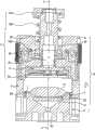
Fig. 2 is the cutaway view along the I-I of Fig. 1 that is in same position, wherein capsule is kept in position;
Fig. 3 is the cutaway view along the II-II of Fig. 2 that is in the capsule insertion position of inclination;
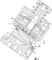
Fig. 4 is the decomposition diagram according to assembly of the present invention;
Fig. 5 is the cutaway view along the I-I of Fig. 1, but is in the position of assembly around the capsule sealing;
Fig. 6 is the cutaway view along the II-II of Fig. 1, but is in the capsule drain position;
Fig. 7 is the maintenance of assembly of the present invention and the detailed view of positioner.
The specific embodiment
Referring to figs. 1 through 5,extraction assembly 1 comprises and is used for receivecapsules 12 and by making water flow through the extraction element that this capsule extracts from this capsule liquid extract under certain pressure.This extraction element hasfirst sub-component 10 andsecond sub-component 11, and this first sub-component is preferably fixing, this second sub-component preferably movable and cooperate withsub-component 10sealings.Sub-component admittance first sub-component 10 hascapsule opening member 22, and thisopening member 22 is generally concave-convex-piece (reliefelement), for example forms a plurality of tapered zones of the part ofpressure distribution plate 21.
This body comprises also and is used for the centre bore 80 thatpiston 20 passes through that this piston forms the part of movable extraction sub-component.The hole 80 that this piston passes body is mounted, and withextract sprayer unit 5 and be connected integratedly, thisdevice 5 comprises that one has the admittance zone of thepiercing member 50 that is used to open capsule.Piston 20 andsprayer unit 5 are coaxial to be assembled into independent parts, and is provided withintake tunnel 51 so that bysprayer unit 5 dispensing water.
Piston passes this body and flexibly installs againstcompression spring 150, and this compression spring is arranged between the interior cavity ofring 140 on the end that is fixed on piston and body.Use seal 30,160 to realize sealing between the inside of piston and body, these seals are arranged on each side of the ring baffle between the inside that is formed at piston and body.Thereby two seals 30,160 limit abalancing gate pit 81 between the inside of piston and body, expand under the effect of the hydraulic fluid that enters this chamber that this balancing gate pit can provide at thefluid inlet 82 at the top (Fig. 3) by being positioned at body.
Therefore, should be understood that because the compression (power) that thespring 150 of having an effect applies mainly the movable sub-component that is made ofpiston 20 andsprayer unit 5 is maintained at the position that extraction chamber wherein opens between thering 140 of piston andbody 8, that is, away from the position in the admittance zone of stator assembly.Like this, enterbalancing gate pit 81 by making hydraulic fluid, compressible this spring, thereby along piston and the sprayer unit of sealing direction F1 promotion as single parts.
In the open position of Fig. 1 to 3, between tworelative admittance zones enough spaces 14, so that can insertcapsule 12 by slit 15.Capsule can manually or with semi-automatic or automatic loading device be inserted byslit 15 by the user, and these chargers are not explanation in this application.
According to the present invention, maintenance andpositioning element 9 are set, betweenmovable sub-component 11 andstator assembly 10 with the appropriate location in the sealing surface P that capsule is remained on assembly.Particularly in Fig. 7 as seen, keep and positioningelement 9 is arranged to, utilizing partly, opening portion ground makes capsule maintain static along the axis of a plurality of directions for columnar part 90.These parts also have the annular targeting part of installing around thebase portion 6 of fixing extraction sub-component 91.This targeting part 91 is with the maintenance shoulder of thedischarger 7 that is preferably ring-type (will describe in detail in this manual after a while) as the edge that keeps capsule.As shown in Figure 3, when being inserted into, the edge of capsule is also kept by the upper peripheral edge ofbase portion 6, can realize sealing when sprayer unit descends on this upper peripheral edge.On each side of these parts, these parts extend two finger 93,94 alongbody 8, and these two finger are bonded in the direction recess 83,84 of body.These finger are connected to the upper end of this groove by elastic reset spring 85, when this assembly is opened, this back-moving spring should keep and positioningelement 9 remains on the holding position, promptly,cylindrical shape part 90 position ofenclosure space 14 partly wherein, concrete is described outlet of sealing and edge on the direction vertical with the direction ofoutlet 16.
Thecylindrical shape part 90 of these parts is positioned to part around thezone 2 that is used for receive capsules.Preferably,part 90 is admitted the periphery in zone near this, andedge 120 how much complementations of its shape and capsule, preferably extends on the circumference of 100-180 degree, so that keep capsule along the axis of a plurality of directions, and guarantees that capsule is positioned at the center.Preferably, the part in this partially enclosedspace 14 is so that center on a side relative with slit 15.Therefore, with respect to being used for the straight-line displacement campaign that actuating activity sub-component is the device ofpiston 20 andsprayer unit 5, center onbase portion 6 installingcomponent 9 coaxially along axis I.
This extraction assembly also hascapsule output mechanism 7, and this mechanism helps to separate capsule and it is discharged this assembly after extracting.In fact this capsule discharge effect should work in extraction that quantity is not limit circulation reliably, and needn't manually remove in this system by wedging or the capsule that blocks.Provide this output mechanism with the rising capsule and make it break away from admit the surface in zone 2.During milking, owing in the encapsulated part, inject water, so capsule bears very big internal pressure.Open capsule by tearing the material that contacts with the concave-convex-piece of pressure distribution plate.Therefore, after extracting, the surface of capsule must outwards be applied power to separate and the discharge capsule from admitting region surface by the concave-convex-piece of pressure distribution plate " punching press ".
This output mechanism is arranged to, elastic tension when extracting the sub-component sealing for two, and when these two extraction sub-components reopen, discharge to cause discharge from the elastic tension state.For this reason,output mechanism 7 comprises a bar, and this bar comprises ring portion 71 andend 72, and this end is hinged on thehinge pin 62 on thebase portion 6 of fixing extraction sub-component.The diameter of the ring portion of this bar close to allow extraction assembly, but this diameter is less than the diameter at the edge of capsule, so that can engage this edge and separate capsule much larger than admitting zone 2.Preferably, in the equilbrium position,bar 70 is accommodated in therecess 95 that forms in this maintenance and the positioning element 9.For bar is triggered to drain position, this maintenance and positioning element have elastic component 92, and its form is the blade that is fixed on the periphery ofparts 9, end 72 synergies of this elastic component and bar.The free part of elastic component 92 is extended aboverecess 95 so that can contact with the end of bar, and its effect is a rising ring portion when discharging.
As shown in Fig. 2 and 4, be provided for locking the mechanism of this maintenance andpositioning element 9, so that using discharger to discharge holdingmember 9 withdrawals between gleocystic stage at retracted position.This locking mechanism has two composition surfaces 96,97, and this composition surface is positioned on the end of finger 93,94 of parts.When the base portion along fixing extraction sub-component reducedparts 9, surface 96,97 cooperated locking with two protuberances 86,87 in the direction recess 83,84 that is contained in body.
At last, also be provided for the mechanism of this maintenance of release andpositioning element 9, thereby these parts can return its initial maintenance and the position location of Fig. 1 and 2.This mechanism comprises the protuberance 98,99 of the finger that is positioned atparts 9, and this protuberance is designed to be positioned at the hook that makes progress in week 220,221 actuatings of piston when piston raises.
The operation principle of extraction assembly will be described below, so that understand the step of inserting, seal, open and discharge capsule.
Fig. 3 illustrates and extracts the assembly that sub-component is positioned at open position.This assembly preferably is inclined relative to horizontal, and facilitates the use gravity and inserts and discharge capsule.This gradient can be between the 5-90 degree, preferably between the 20-80 degree.Under the effect ofcompression spring 150, piston is maintained at retracted position to produce enough spaces 14.This maintenance and centeringpart 9 utilize back-moving spring 85 to be bonded on the position that is used to keep and locate capsule.Thereby can insert capsule by slit 15.When capsule inserted, theedge 120 of capsule was near the part withcomplementary shape 90 of these parts, thereby capsule is centered in the centre of extracting the zone.Thereby capsule can freely be placed in againstpressure distribution plate 21 to be admitted on thezone 2.
Fig. 5 illustrates the step of closed component.Comepower piston 20 by hydraulic fluid being introduced balancing gate pit 81.Plungeractuation sprayer unit 5, thus thisdevice 5 seals along the F1 direction against capsule.Along with piston reduces, the lower limb by piston pushes back this maintenance andpositioning element 9, is in the retracted position of the bottom ofbase portion 6 up to these parts.When sealing finishes, this activity sub-component tensioning output mechanism 7.Particularly, theseal 52 of sprayer unit remains on crooked place withbar 70, simultaneously the elastic component ofparts 9 sinceparts 9 with respect to the relative motion of theend 72 of bar and elastic bending.Whenparts 9 descended, the end that (bar) is fixed forced movable vane 92 bendings, thus the tensioning output mechanism.
When assembly seals, utilize locking mechanism subsequentlyparts 9 to be automatically locked at retracted position.More specifically, composition surface 96,97 cooperations of the finger ofparts 9 are resisted against on the composition surface 86,87 of body, thus fixing and LockPart 9.
The extraction operation of extracting liquid extract under the heat hydraulic pressure itself is known, does not need to illustrate in this application.
Fig. 6 illustrates and reopens and discharge step.By being raise along the F2 direction,piston 20 andsprayer unit 5 reopen.With by when being released in tension force that closed period producesdischarging output mechanism 7 gradually in blade,parts 9 are still locked by above-mentioned locking mechanism at the rising piston.Then, the bar of output mechanism pivots aroundhinge pin 62, thereby separates capsule, and capsule is further tilted with respect to the vertical plane onoutlet 16 1 sides.Then, capsule falls under gravity into the container (not shown) that is used for (placement) capsulae vacuus.Output mechanism is along with the rising of piston is worked.Then at the end of piston stroke, hook 220,221 releasingparts 9 of piston, this hook acts on the protuberance 98,99, finger 93,94 is removed and is broken away from this composition surface.Then,parts 9 return by back-moving spring 84,85 and keep and the position location.
The present invention relates to a kind of beverage dispenser of the quantitative in advance capsule that uses any kind or extraction assembly on the machine of being installed in.According to required capacity, dispenser or machine can comprise one or more assemblies.Assembly of the present invention provides more reliable and loading/extraction faster/discharge circulation than available usually circulation.
Claims (17)
1. one kind is used for comprising from the assembly that extracts under pressure (1) of capsule (12) the preparation beverage that comprises material to be extracted:
Comprise first and extract the extraction element that sub-component (10) and second extracts sub-component (11), this second extraction sub-component can move to be enclosed on this first extraction sub-component, thereby in being formed on sealing surface (P), surrounds detent position the extraction chamber (13) of this capsule, and at open position, extracting the space (14) that keeps enough between the sub-component at these two extracts between the sub-component to allow this capsule to insert these two
Be used for this capsule being kept and being positioned at these two devices (9) that extract between the sub-component (10,11), this device partly seals the space (14) of opening and extracts between the sub-component this capsule is remained on these two;
It is characterized in that, this maintenance and positioner (9) can move coaxially with this second straight-line displacement of extracting sub-component, and can be back into retracted position along straight line by this second extraction sub-component (11), thereby make these two to extract sub-components (10,11) can be around this capsule sealing
This maintenance and positioner are taked to make the form of this capsule at the single parts of the space centered that this is opened along a plurality of axis in this sealing surface (P),
This first extracts sub-component (10) and comprises base portion (6), and should keep and positioner (9) around described first base portion (6) installation of extracting sub-component (10).
2. assembly according to claim 1, it is characterized in that, this maintenance and positioner (9) have and are used to the open circles cylindrical portion (90) that keeps capsule (12) and this capsule is centered, and the annular targeting part of installing around this first base portion (6) that extracts sub-component (10) (91).
3. according to any one the described assembly in the aforementioned claim, it is characterized in that, be provided with the capsule discharger (7) that is used for capsule is discharged this assembly.
4. assembly according to claim 3, it is characterized in that, during opening,, utilize this second straight line reset response that extracts sub-component to make described capsule discharger (7) work along with this second extraction sub-component (11) breaks away from this first extraction sub-component (10).
5. assembly according to claim 3, it is characterized in that, when this first and second extractions sub-component (10, when 11) sealing, this maintenance and positioner (9) are locked at this retracted position, and only after this capsule discharger (7) has been discharged capsule, be unlocked to return maintenance and position location.
6. assembly according to claim 3 is characterized in that, when this second extraction sub-component (11) breaks away from, utilizes this second directly this maintenance and positioner (9) release of realization to being in this retracted position of straight line reset response of extracting sub-component.
7. assembly according to claim 6 is characterized in that, at this second end that extracts the straight line return stroke of sub-component (11), this is kept and positioner (9) release.
8. assembly according to claim 3 is characterized in that, this capsule discharger (7) is configured to along the direction different with direction of insertion capsule (12) be discharged this assembly.
9. assembly according to claim 8 is characterized in that, this capsule discharger (7) is configured to along the direction opposite with direction of insertion capsule (12) be discharged this assembly.
10. assembly according to claim 3 is characterized in that, when these two extraction sub-components (10, when 11) sealing, this capsule discharger (7) elastic tension, and when these two extraction sub-components reopened, this capsule discharger discharged so that discharge from its elastic tension state.
11. assembly according to claim 10 is characterized in that, by elastic tension, this elastic tension spare forms the part of this maintenance and positioner to this capsule discharger (7) by contacting with at least one elastic tension spare (92).
12. assembly according to claim 10, it is characterized in that, this capsule discharger (7) comprises that form is the bar (70) of ring, this bar is hinged on this first extraction sub-component, and described bar is tensioned by contacting with at least one the sheet spring (92) that is supported by this maintenance and positioner (9).
13. assembly according to claim 1 is characterized in that, this second extraction sub-component (11) has piston type straight line actuating device (20,30,140,150), and this actuating device can be activated to seal by hydraulic pressure or electric device.
14. assembly according to claim 1 is characterized in that, this first extraction sub-component (10) is fixed.
15. assembly according to claim 14 is characterized in that, this first extracts sub-component (10) and comprises that the capsule with the concave-convex-piece that is used to open capsule admits the zone.
16. assembly according to claim 15 is characterized in that, this second extraction sub-component comprises the device (50,51) that complementary capsule is admitted zone (5) and is used for supplying water to this capsule.
17. assembly according to claim 16 is characterized in that, described being used for comprises that to the device that this capsule supplies water capsule punctures part (50).
Applications Claiming Priority (2)
| Application Number | Priority Date | Filing Date | Title |
|---|---|---|---|
| EP03002817.9 | 2003-02-07 | ||
| EP03002817AEP1444932B1 (en) | 2003-02-07 | 2003-02-07 | Linear extraction unit for the preparation under pressure of a drink from a cartridge |
Publications (2)
| Publication Number | Publication Date |
|---|---|
| CN1747676A CN1747676A (en) | 2006-03-15 |
| CN100496355Ctrue CN100496355C (en) | 2009-06-10 |
Family
ID=32605353
Family Applications (1)
| Application Number | Title | Priority Date | Filing Date |
|---|---|---|---|
| CNB200480003653XAExpired - Fee RelatedCN100496355C (en) | 2003-02-07 | 2004-01-22 | Extraction assembly with linear sealing unit for the preparation under pressure of a drink from a cartridge |
Country Status (26)
| Country | Link |
|---|---|
| US (3) | US7562618B2 (en) |
| EP (1) | EP1444932B1 (en) |
| JP (1) | JP4288280B2 (en) |
| CN (1) | CN100496355C (en) |
| AR (1) | AR043123A1 (en) |
| AT (1) | ATE316349T1 (en) |
| AU (1) | AU2004212280B2 (en) |
| BG (1) | BG109238A (en) |
| BR (1) | BRPI0407326A (en) |
| CA (1) | CA2514147C (en) |
| CL (1) | CL2004000216A1 (en) |
| CZ (1) | CZ2005563A3 (en) |
| DE (1) | DE60303320T2 (en) |
| DK (1) | DK1444932T3 (en) |
| ES (1) | ES2256601T3 (en) |
| HU (1) | HUP0500841A2 (en) |
| IL (1) | IL169490A0 (en) |
| MX (1) | MXPA05007980A (en) |
| NO (1) | NO20054069L (en) |
| PL (1) | PL377353A1 (en) |
| RU (1) | RU2339288C2 (en) |
| SI (1) | SI1444932T1 (en) |
| TW (1) | TW200507786A (en) |
| UA (1) | UA79857C2 (en) |
| WO (1) | WO2004071259A1 (en) |
| ZA (1) | ZA200507152B (en) |
Cited By (2)
| Publication number | Priority date | Publication date | Assignee | Title |
|---|---|---|---|---|
| CN103763999A (en)* | 2011-08-25 | 2014-04-30 | 雀巢产品技术援助有限公司 | Cartridge positioning system |
| CN105939641A (en)* | 2013-12-02 | 2016-09-14 | 诺威德尔塔咖啡贸易工业有限公司 | Extraction device of simplified actuation and process of operation thereof |
Families Citing this family (94)
| Publication number | Priority date | Publication date | Assignee | Title |
|---|---|---|---|---|
| EP1495702A1 (en) | 2003-07-10 | 2005-01-12 | Nestec S.A. | Device for the extraction of a cartridge |
| ITTO20040374A1 (en)* | 2004-06-04 | 2004-09-04 | Sgl Italia Srl | PERCOLATING MACHINE FOR THE PREPARATION OF A DRINK |
| DK1702543T3 (en) | 2004-10-25 | 2008-01-07 | Nestec Sa | Capsule with sealants |
| ITMI20050854A1 (en)* | 2005-05-12 | 2006-11-13 | Perfect Steam Appliances Ltd | INFUSION GROUP FOR DRINK PREPARATION MACHINES |
| PT1767129E (en)* | 2005-09-27 | 2008-11-11 | Nestec Sa | Extraction module for a capsule-based beverage production device |
| EP1839543B1 (en) | 2006-03-31 | 2008-06-25 | Nestec S.A. | Capsule with outer sealing material pressurized by a fluid |
| EP1859714B2 (en)* | 2006-05-24 | 2015-05-27 | Nestec S.A. | Brewing device and brewing capsule system with a capsule holder for facilitating insertion and removal of capsules |
| ITMI20061307A1 (en) | 2006-07-06 | 2008-01-07 | Perfect Steam Appliances Ltd | INFUSION GROUP FOR MACHINE FOR THE PREPARATION OF DRINKS |
| FR2904205B1 (en)* | 2006-07-26 | 2012-04-06 | Cie Mediterraneenne Des Cafes | DEVICE AND METHOD FOR PRODUCING BEVERAGES BY INFUSION |
| ITFI20060194A1 (en)* | 2006-08-04 | 2008-02-05 | Saeco Ipr Ltd | INFUSION DEVICE FOR THE PREPARATION OF DRINKS FROM SINGLE-DOSE CAPSULES |
| DE602006006675D1 (en)* | 2006-08-30 | 2009-06-18 | Nestec Sa | Capsule for making beverages |
| ITFI20070028A1 (en) | 2007-02-07 | 2008-08-08 | Saeco Ipr Ltd | INFUSION DEVICE FOR THE PREPARATION OF DRINKS FROM SINGLE-DOSE CAPSULES WITH A CAPSULES CENTERING DEVICE. |
| ATE431712T1 (en)* | 2007-03-06 | 2009-06-15 | Nestec Sa | SYSTEM FOR PRODUCING A BEVERAGE FROM A CAPSULE AND METHOD |
| PL1967099T3 (en)* | 2007-03-06 | 2010-06-30 | Nestec Sa | Device for preparing a food liquid from a capsule |
| US10722066B2 (en)* | 2010-12-04 | 2020-07-28 | Adrian Rivera | Windowed single serving brewing material holder |
| US11832755B2 (en)* | 2007-07-13 | 2023-12-05 | Adrian Rivera | Brewing material container for a beverage brewer |
| ATE525943T1 (en)* | 2007-08-29 | 2011-10-15 | Nestec Sa | DISPENSING DEVICE FOR PREPARING AND DISPENSING A FOOD AND/OR A NUTRITIONAL COMPOSITION |
| CN102133047B (en) | 2007-10-04 | 2014-04-30 | 雀巢产品技术援助有限公司 | Heating device with an integrated thermoblock for a beverage preparation machine |
| EP2218369B1 (en) | 2007-10-04 | 2017-05-03 | Nestec S.A. | Beverage brewing unit |
| CL2008002963A1 (en) | 2007-10-04 | 2010-01-22 | Nestec Sa | Heating device for a machine for the preparation of liquid food or drink, comprising a thermal unit with a metallic mass, through which the liquid circulates, and accumulates heat and supplies it to the liquid, and has one or more insured electrical components rigidly to the thermal unit; and machine. |
| DE602007012913D1 (en)* | 2007-12-18 | 2011-04-14 | Nestec Sa | Device for producing a drink with replaceable injection element |
| EP2316311B1 (en)* | 2008-01-15 | 2013-12-04 | Nestec S.A. | Sealing adapter for a beverage extraction system suitable for preparing a beverage from cartridges |
| EP2265156B1 (en)* | 2008-03-14 | 2013-05-15 | Mocoffee AG | Apparatus and capsule for making a drink |
| EP2105074B1 (en)* | 2008-03-28 | 2011-07-20 | Delica AG | Device and array for preparing a liquid food or luxury article and portion packaging |
| JP2011518015A (en)* | 2008-04-22 | 2011-06-23 | ネステク ソシエテ アノニム | Module assembly for beverage production equipment |
| EP2309900B1 (en)* | 2008-08-08 | 2015-05-27 | Nestec S.A. | Beverage machine with carrying handle and configurable appearance&side functions |
| ES2432621T3 (en)* | 2008-09-13 | 2013-12-04 | Ethical Coffee Company Sa | Device for the preparation of a drink |
| IT1392019B1 (en)* | 2008-12-10 | 2012-02-09 | Capitani Srl | INFUSION GROUP |
| IT1392573B1 (en)* | 2008-12-30 | 2012-03-09 | Lavazza Luigi Spa | INFUSION GROUP FOR A DRINK PREPARATION MACHINE |
| IT1392572B1 (en)* | 2008-12-30 | 2012-03-09 | Lavazza Luigi Spa | INFUSION GROUP FOR A DRINK PREPARATION MACHINE |
| CN201356446Y (en)* | 2008-12-30 | 2009-12-09 | 薛胜利 | Novel capsule-type coffee maker |
| IT1393007B1 (en)* | 2009-03-12 | 2012-04-11 | Emmebielle S R L | MACHINE FOR THE PREPARATION BY MEANS OF DRINKS BY MEANS OF CAPSULES |
| US8721568B2 (en) | 2009-03-31 | 2014-05-13 | Depuy (Ireland) | Method for performing an orthopaedic surgical procedure |
| US8551023B2 (en)* | 2009-03-31 | 2013-10-08 | Depuy (Ireland) | Device and method for determining force of a knee joint |
| WO2010137959A1 (en)* | 2009-06-17 | 2010-12-02 | Sara Lee/De N.V. | System and method for preparing a predetermined quantity of beverage |
| PT2312978E (en) | 2009-07-23 | 2013-11-11 | Ethical Coffee Company Sa | Device for preparing a drink extracted from a capsule |
| BR112012007816A2 (en)* | 2009-10-05 | 2016-08-30 | Nestec Sa | ergonomic capsule extraction device |
| US8973488B2 (en)* | 2009-10-05 | 2015-03-10 | Nestec S.A. | Cartridge extraction device |
| CN102939033B (en)* | 2010-03-19 | 2015-09-30 | N&W全球自动售货股份公司 | Brewing assembly |
| FR2960402B1 (en)* | 2010-05-25 | 2013-01-11 | Cie Mediterraneenne Des Cafes | INFUSION BEVERAGE PRODUCTION SYSTEM |
| IT1400433B1 (en)* | 2010-06-01 | 2013-05-31 | Lavazza Luigi Spa | INFUSION SYSTEM FOR A DRINK PREPARATION MACHINE. |
| IT1400432B1 (en)* | 2010-06-01 | 2013-05-31 | Lavazza Luigi Spa | INFUSION SYSTEM FOR A DRINK PREPARATION MACHINE. |
| US10071851B2 (en) | 2010-07-12 | 2018-09-11 | Robert Bao Vu | Apparatus and products for producing beverages, and methods for making and using same |
| SMT201900157T1 (en)* | 2010-07-22 | 2019-05-10 | K Fee System Gmbh | Portion capsule having an identifier |
| EP2608704B1 (en)* | 2010-08-27 | 2016-06-22 | Nestec S.A. | Simple motorized brewing unit |
| CN101953638B (en)* | 2010-09-26 | 2013-05-01 | 广东新宝电器股份有限公司 | Funnel of coffee machine |
| JP5796852B2 (en)* | 2010-10-08 | 2015-10-21 | キュー・ビー・オー・コーヒー・ゲゼルシャフト・ミット・ベシュレンクテル・ハフツングQbo Coffee Gmbh | Extraction device and sealing system |
| US9510705B2 (en)* | 2011-04-13 | 2016-12-06 | Patrick J. Rolfes | Pre-packaged beverage brewer press |
| CA2840909A1 (en)* | 2011-07-12 | 2013-01-17 | Nestec S.A. | Actuator for closing a beverage ingredient holder |
| ITTV20110105A1 (en)* | 2011-07-21 | 2013-01-22 | Hausbrandt Trieste 1829 Spa | DEVICE FOR THE DRILLING OF A SINGLE-DOSE CAPSULE FOR A POWDER AND SIMILAR SUBSTANCE |
| RU2014111180A (en)* | 2011-08-25 | 2015-09-27 | Нестек С.А. | CARTRIDGE PUNCH PUNCH WITH LONG SERVICE LIFE |
| FR2988988B1 (en)* | 2012-04-04 | 2014-06-27 | Technopool Sarl | BEVERAGE INFUSION BEVERAGE PREPARATION DEVICE WITH SWIVEL CRADLE |
| JP2015534486A (en)* | 2012-10-09 | 2015-12-03 | ネステク ソシエテ アノニム | Beverage machine equipped with ingredient capsule attachment device |
| US10092130B2 (en)* | 2012-11-12 | 2018-10-09 | Nestec S.A. | Opener for making large openings in capsules |
| CN104510351B (en)* | 2013-09-30 | 2017-09-22 | 胡剑彧 | A kind of extraction mechanism of coffee machine |
| EP2856917A1 (en)* | 2013-10-01 | 2015-04-08 | Luna Technology Systems LTS GmbH | Brewing module |
| PT107335B (en) | 2013-12-02 | 2020-07-13 | Novadelta - Comércio E Indústria De Cafés, Lda. | SIMPLIFIED CONSTRUCTION EXTRACTION DEVICE AND BEVERAGE PREPARATION SYSTEM INCLUDING THIS DEVICE |
| CN104083086B (en)* | 2014-06-20 | 2016-08-31 | 广东新宝电器股份有限公司 | Piercing member for beverage extraction |
| ES2699086T3 (en) | 2014-07-09 | 2019-02-07 | Nestec Sa | Accessory to automatically supply a beverage machine with a liquid from a distribution network |
| WO2016005348A1 (en) | 2014-07-09 | 2016-01-14 | Nestec S.A. | Device for connecting a beverage machine to a distribution network with safe flow interruption |
| US10595670B2 (en) | 2014-07-09 | 2020-03-24 | Societe Des Produits Nestle S.A. | Coupling of a device for connecting a beverage machine to a distribution network |
| EP3166457B1 (en) | 2014-07-09 | 2019-10-09 | Société des Produits Nestlé S.A. | Device for connecting a beverage machine to a distribution network with safe monitoring |
| BR102014018473B1 (en)* | 2014-07-28 | 2022-02-08 | B.Blend Máquinas E Bebidas S.A. | REMOVABLE DEVICE FOR SUPPORTING BEVERAGE CAPSULES |
| CN106998955B (en)* | 2014-09-29 | 2020-04-14 | 路易吉·拉瓦扎股份公司 | Dispensing components for machines for preparing liquid food products |
| RU2017115547A (en)* | 2014-10-08 | 2018-11-12 | Нестек С.А. | EXTRACTION UNIT FOR DRINKS |
| CA3207639A1 (en) | 2014-10-20 | 2016-04-28 | Bedford Systems Llc | Cartridge holder for beverage machine |
| ES2570877B1 (en)* | 2014-11-17 | 2017-03-03 | Bonesil Expansion, S.L. | Procedure of elaboration and conservation of olive paste |
| EP3282902B1 (en)* | 2015-04-13 | 2024-02-14 | The Richards Corporation | Method for puncturing a beverage capsule prior to its insertion into a brewing machine |
| CN105193272A (en)* | 2015-05-28 | 2015-12-30 | 宁波西文电器有限公司 | Capsule box set arrangement and extraction mechanism |
| ITUB20155389A1 (en)* | 2015-11-09 | 2017-05-09 | Sarong Spa | CAPPULE FOR BEVERAGES |
| US11284738B2 (en) | 2015-11-11 | 2022-03-29 | Societe Des Produits Nestle S.A. | Easy connection of a liquid tank to a beverage machine |
| USD864838S1 (en) | 2016-03-24 | 2019-10-29 | Mission LLC | Wake diverter |
| US10059404B2 (en) | 2016-03-24 | 2018-08-28 | Mission LLC | Wake diverter |
| PT109303B (en)* | 2016-04-07 | 2021-02-15 | Novadelta Comercio Ind Cafes Sa | EXTRACTION DEVICE WITH MOBILE CAPSULE SUPPORT |
| CA3041722A1 (en) | 2016-11-09 | 2018-05-17 | Pepsico, Inc. | Carbonated beverage makers, methods, and systems |
| US12409915B2 (en) | 2017-08-29 | 2025-09-09 | Mcnaughton Incorporated | Wake shaping apparatus and related technology |
| US10183726B1 (en) | 2017-08-29 | 2019-01-22 | Mcnaughton Incorporated | Wake shaping apparatus and related technology |
| FR3075492B1 (en)* | 2017-12-20 | 2020-01-03 | Silec Cable | DEVICE FOR STRIPPING A CABLE |
| EP3727102A1 (en)* | 2017-12-22 | 2020-10-28 | Société des Produits Nestlé S.A. | Multi-serve airtight coffee dispenser |
| US11284735B2 (en)* | 2018-12-27 | 2022-03-29 | Rockwell Collins, Inc. | Brew head assembly |
| KR102259987B1 (en)* | 2019-11-15 | 2021-06-02 | 청호나이스 주식회사 | Apparatus of extracting beverage from capsule containing raw material for beverage |
| USD953960S1 (en) | 2020-03-09 | 2022-06-07 | Swell Ventures LLC | Water flow deflection device |
| US11225307B2 (en) | 2020-03-13 | 2022-01-18 | Swell Ventures LLC | Water flow deflection device for a watercraft and methods of use |
| US11214338B2 (en) | 2020-03-13 | 2022-01-04 | Swell Ventures LLC | Adjustable water flow deflection device for a watercraft and methods of use |
| USD953961S1 (en) | 2020-03-13 | 2022-06-07 | Swell Ventures LLC | Adjustable water flow deflection device |
| US11805934B1 (en)* | 2020-10-21 | 2023-11-07 | Adrian Rivera | Brewing material lid and container for a beverage brewer |
| IL288138A (en)* | 2020-12-02 | 2022-07-01 | Hamat Sanitary Fittings And Castings Ltd | A split system for making a drink |
| IT202100014012A1 (en)* | 2021-05-28 | 2022-11-28 | Arteq S R L | Dispensing group for machines for the preparation of capsule drinks |
| DE102021123554A1 (en) | 2021-09-10 | 2023-03-16 | Eugster / Frismag Ag | Lockable brewing unit |
| MX2024006477A (en)* | 2021-12-21 | 2024-06-19 | Nestle Sa | DRINK POD SYSTEM WITH POD EJECTOR. |
| CN119731097A (en) | 2022-09-12 | 2025-03-28 | 雀巢产品有限公司 | Beverage extraction system |
| AU2023342231A1 (en) | 2022-09-12 | 2025-01-23 | Société des Produits Nestlé S.A. | Beverage extraction system |
| KR20250099687A (en) | 2022-11-07 | 2025-07-02 | 소시에떼 데 프로듀이 네슬레 소시에떼아노님 | Beverage making machine |
| WO2025011786A1 (en) | 2023-07-07 | 2025-01-16 | Société des Produits Nestlé S.A. | Piercing arrangement and related beverage extraction system |
Family Cites Families (11)
| Publication number | Priority date | Publication date | Assignee | Title |
|---|---|---|---|---|
| CH673083A5 (en)* | 1987-07-17 | 1990-02-15 | Turmix Ag | |
| EP0512142A1 (en)* | 1991-05-08 | 1992-11-11 | Societe Des Produits Nestle S.A. | Method for producing beverages by means of sealed cartridges and apparatus for accomplishing the method |
| FR2709655B1 (en)* | 1993-09-06 | 1995-11-24 | Cafes Cie Mediterraneenne | Express coffee machine using ground coffee packaging of the pre-dosed tablet type. |
| UA29495C2 (en)* | 1993-12-20 | 2000-11-15 | Компані Медітерранеенн Де Кафе (С.А.) | Automatic device to make hot drinks by means of brewing |
| AU2704397A (en) | 1997-04-21 | 1998-11-13 | Compagnie Mediterraneenne Des Cafes (S.A.) | Method for transforming an espresso-coffee maker with vertical coffee extractioninto a machine with horizontal extraction and transformed machine |
| WO2000038558A1 (en) | 1998-12-24 | 2000-07-06 | Compagnie Mediterraneenne Des Cafes (Societe Anonyme) | Extraction chamber for an automatic machine preparing hot drinks |
| US6079315A (en)* | 1999-01-19 | 2000-06-27 | Keurig, Inc. | Beverage filter cartridge holder |
| GB9901702D0 (en) | 1999-01-27 | 1999-03-17 | Reckitt & Colman Inc | Improvements in or relating to organic compositions |
| PT1090574E (en) | 1999-08-31 | 2005-02-28 | Nestle Sa | DEVICE FOR EXTRACTION OF A SUBSTANCE FOR THE PREPARATION OF A DRINK |
| DK1095605T3 (en) | 1999-10-28 | 2005-01-24 | Nestle Sa | Capsule ejection device |
| IT1321007B1 (en)* | 2000-02-07 | 2003-12-18 | Francesco Bonanno | AUTOMATIC GROUP FOR THE EXPLOITATION OF COFFEE AND OTHER BEVERAGES WITH HYDRAULIC DRIVE |
- 2003
- 2003-02-07DEDE60303320Tpatent/DE60303320T2/ennot_activeExpired - Lifetime
- 2003-02-07EPEP03002817Apatent/EP1444932B1/ennot_activeExpired - Lifetime
- 2003-02-07ESES03002817Tpatent/ES2256601T3/ennot_activeExpired - Lifetime
- 2003-02-07ATAT03002817Tpatent/ATE316349T1/ennot_activeIP Right Cessation
- 2003-02-07DKDK03002817Tpatent/DK1444932T3/enactive
- 2003-02-07SISI200330174Tpatent/SI1444932T1/enunknown
- 2004
- 2004-01-22RURU2005127855/12Apatent/RU2339288C2/ennot_activeIP Right Cessation
- 2004-01-22CNCNB200480003653XApatent/CN100496355C/ennot_activeExpired - Fee Related
- 2004-01-22UAUAA200508557Apatent/UA79857C2/enunknown
- 2004-01-22BRBRPI0407326-6Apatent/BRPI0407326A/ennot_activeIP Right Cessation
- 2004-01-22USUS10/544,014patent/US7562618B2/ennot_activeExpired - Fee Related
- 2004-01-22MXMXPA05007980Apatent/MXPA05007980A/enactiveIP Right Grant
- 2004-01-22JPJP2006501575Apatent/JP4288280B2/ennot_activeExpired - Fee Related
- 2004-01-22PLPL377353Apatent/PL377353A1/enunknown
- 2004-01-22WOPCT/EP2004/000498patent/WO2004071259A1/ennot_activeApplication Discontinuation
- 2004-01-22HUHU0500841Apatent/HUP0500841A2/enunknown
- 2004-01-22CACA2514147Apatent/CA2514147C/ennot_activeExpired - Fee Related
- 2004-01-22AUAU2004212280Apatent/AU2004212280B2/ennot_activeCeased
- 2004-01-22CZCZ20050563Apatent/CZ2005563A3/enunknown
- 2004-02-06CLCL200400216Apatent/CL2004000216A1/enunknown
- 2004-02-06ARARP040100388Apatent/AR043123A1/enunknown
- 2004-02-06TWTW093102795Apatent/TW200507786A/enunknown
- 2005
- 2005-06-30ILIL169490Apatent/IL169490A0/enunknown
- 2005-07-20BGBG109238Apatent/BG109238A/enunknown
- 2005-09-01NONO20054069Apatent/NO20054069L/ennot_activeApplication Discontinuation
- 2005-09-06ZAZA200507152Apatent/ZA200507152B/enunknown
- 2009
- 2009-02-25USUS12/392,805patent/US8256342B2/ennot_activeExpired - Fee Related
- 2009-06-17USUS12/486,478patent/US8336447B2/ennot_activeExpired - Fee Related
Cited By (3)
| Publication number | Priority date | Publication date | Assignee | Title |
|---|---|---|---|---|
| CN103763999A (en)* | 2011-08-25 | 2014-04-30 | 雀巢产品技术援助有限公司 | Cartridge positioning system |
| CN105939641A (en)* | 2013-12-02 | 2016-09-14 | 诺威德尔塔咖啡贸易工业有限公司 | Extraction device of simplified actuation and process of operation thereof |
| CN105939641B (en)* | 2013-12-02 | 2020-01-07 | 诺威德尔塔咖啡贸易工业有限公司 | Simply driven extraction device and method of operation thereof |
Also Published As
Similar Documents
| Publication | Publication Date | Title |
|---|---|---|
| CN100496355C (en) | Extraction assembly with linear sealing unit for the preparation under pressure of a drink from a cartridge | |
| CN100490717C (en) | Method for preparing a beverage from powdered material in a sealed capsule | |
| CA2441475C (en) | Extracting device with integrated capsule loading system | |
| EP1776026B1 (en) | Percolator machine for making a beverage | |
| AU2007280799B2 (en) | Infusion device to prepare beverages from single-serving capsules | |
| RU2444271C2 (en) | Brewing device to prepare beverages from disposable capsules with capsule alignment device | |
| KR101141563B1 (en) | Capsule extraction device | |
| AU2005200157A1 (en) | Brewing device for a coffee maker | |
| AU2012298465A1 (en) | Cartridge positioning system | |
| JP2014524318A (en) | Cartridge removal system | |
| EP3730007A1 (en) | Brewing device for producing a beverage from a single-serve capsule | |
| AU2012201622B2 (en) | Cap extraction device | |
| HK1084309A (en) | Extraction module with linear closure for the pressurised preparation of a drink from a capsule | |
| WO2008006760A2 (en) | Super automatic machine for brewing coffee or espresso | |
| AU2014240190A1 (en) | Cap extraction device |
Legal Events
| Date | Code | Title | Description |
|---|---|---|---|
| C06 | Publication | ||
| PB01 | Publication | ||
| C10 | Entry into substantive examination | ||
| SE01 | Entry into force of request for substantive examination | ||
| REG | Reference to a national code | Ref country code:HK Ref legal event code:DE Ref document number:1084309 Country of ref document:HK | |
| C14 | Grant of patent or utility model | ||
| GR01 | Patent grant | ||
| REG | Reference to a national code | Ref country code:HK Ref legal event code:WD Ref document number:1084309 Country of ref document:HK | |
| TR01 | Transfer of patent right | Effective date of registration:20190729 Address after:Vevey Patentee after:SOCIETE DES PRODUITS NESTLE S. A. Address before:Vevey Patentee before:Nestec SA | |
| TR01 | Transfer of patent right | ||
| CF01 | Termination of patent right due to non-payment of annual fee | Granted publication date:20090610 Termination date:20210122 | |
| CF01 | Termination of patent right due to non-payment of annual fee |