CN100490992C - Apparatus for extracting paint from containers, container lids and assemblies of containers and lids - Google Patents
Apparatus for extracting paint from containers, container lids and assemblies of containers and lidsDownload PDFInfo
- Publication number
- CN100490992C CN100490992CCNB2005800141846ACN200580014184ACN100490992CCN 100490992 CCN100490992 CCN 100490992CCN B2005800141846 ACNB2005800141846 ACN B2005800141846ACN 200580014184 ACN200580014184 ACN 200580014184ACN 100490992 CCN100490992 CCN 100490992C
- Authority
- CN
- China
- Prior art keywords
- container
- lid
- paint
- neck
- nozzle
- Prior art date
- Legal status (The legal status is an assumption and is not a legal conclusion. Google has not performed a legal analysis and makes no representation as to the accuracy of the status listed.)
- Expired - Lifetime
Links
- 239000003973paintSubstances0.000titleclaimsabstractdescription103
- 230000000712assemblyEffects0.000titledescription2
- 238000000429assemblyMethods0.000titledescription2
- 229920003023plasticPolymers0.000claimsabstractdescription7
- 239000004033plasticSubstances0.000claimsabstractdescription7
- 239000002184metalSubstances0.000claimsdescription18
- 229910052751metalInorganic materials0.000claimsdescription18
- 239000007788liquidSubstances0.000claimsdescription13
- 239000012530fluidSubstances0.000claimsdescription12
- 238000007789sealingMethods0.000claimsdescription11
- 238000011049fillingMethods0.000claimsdescription8
- 238000000576coating methodMethods0.000claimsdescription7
- 239000011248coating agentSubstances0.000claimsdescription4
- NJPPVKZQTLUDBO-UHFFFAOYSA-NnovaluronChemical compoundC1=C(Cl)C(OC(F)(F)C(OC(F)(F)F)F)=CC=C1NC(=O)NC(=O)C1=C(F)C=CC=C1FNJPPVKZQTLUDBO-UHFFFAOYSA-N0.000claims11
- 238000005507sprayingMethods0.000claims5
- 150000002739metalsChemical class0.000claims1
- 238000000034methodMethods0.000description16
- 238000004519manufacturing processMethods0.000description10
- 239000000463materialSubstances0.000description9
- 238000009423ventilationMethods0.000description6
- 230000008901benefitEffects0.000description5
- -1polypropylenePolymers0.000description5
- 239000007787solidSubstances0.000description4
- 239000004743PolypropyleneSubstances0.000description3
- 229920001903high density polyethylenePolymers0.000description3
- 239000004700high-density polyethyleneSubstances0.000description3
- 238000001746injection mouldingMethods0.000description3
- 230000013011matingEffects0.000description3
- 238000002156mixingMethods0.000description3
- 239000002245particleSubstances0.000description3
- 229920001155polypropylenePolymers0.000description3
- 230000008569processEffects0.000description3
- 239000007921spraySubstances0.000description3
- 238000003860storageMethods0.000description3
- 210000003813thumbAnatomy0.000description3
- 239000012780transparent materialSubstances0.000description3
- 238000000071blow mouldingMethods0.000description2
- 210000004247handAnatomy0.000description2
- JEIPFZHSYJVQDO-UHFFFAOYSA-Niron(III) oxideInorganic materialsO=[Fe]O[Fe]=OJEIPFZHSYJVQDO-UHFFFAOYSA-N0.000description2
- 229920001179medium density polyethylenePolymers0.000description2
- 239000004701medium-density polyethyleneSubstances0.000description2
- 239000005020polyethylene terephthalateSubstances0.000description2
- 229920000139polyethylene terephthalatePolymers0.000description2
- 229920000642polymerPolymers0.000description2
- 229910001220stainless steelInorganic materials0.000description2
- 238000003756stirringMethods0.000description2
- 239000004698PolyethyleneSubstances0.000description1
- 230000009471actionEffects0.000description1
- 230000015572biosynthetic processEffects0.000description1
- 230000000903blocking effectEffects0.000description1
- 238000010276constructionMethods0.000description1
- 238000013461designMethods0.000description1
- 238000010586diagramMethods0.000description1
- 238000001035dryingMethods0.000description1
- 238000000605extractionMethods0.000description1
- 210000003811fingerAnatomy0.000description1
- 238000002347injectionMethods0.000description1
- 239000007924injectionSubstances0.000description1
- 238000003780insertionMethods0.000description1
- 230000037431insertionEffects0.000description1
- 238000002372labellingMethods0.000description1
- 229920001684low density polyethylenePolymers0.000description1
- 239000004702low-density polyethyleneSubstances0.000description1
- 230000007246mechanismEffects0.000description1
- 238000012986modificationMethods0.000description1
- 230000004048modificationEffects0.000description1
- 230000010355oscillationEffects0.000description1
- 238000010422paintingMethods0.000description1
- 238000007591painting processMethods0.000description1
- 239000000049pigmentSubstances0.000description1
- 229920000573polyethylenePolymers0.000description1
- 239000002861polymer materialSubstances0.000description1
- 238000002360preparation methodMethods0.000description1
- 230000009467reductionEffects0.000description1
- 230000002787reinforcementEffects0.000description1
- 230000000284resting effectEffects0.000description1
- 238000006748scratchingMethods0.000description1
- 230000002393scratching effectEffects0.000description1
- 239000010935stainless steelSubstances0.000description1
- 238000012546transferMethods0.000description1
- 239000011800void materialSubstances0.000description1
- 238000003466weldingMethods0.000description1
Images


Landscapes
- Closures For Containers (AREA)
Abstract
Description
Translated fromChinese相关申请数据relevant application data
本申请要求2004年3月31日提交的美国临时专利申请第60/557,860号和2004年8月20日提交的美国临时专利申请第60/603,226号的优先权。美国临时专利申请第60/557,860号和第60/603,226号的全文都结合于此作为参照。此外,本申请与2002年4月18日提交的美国专利申请第10/126,481相关联,该美国专利申请要求2001年4月18日提交的美国临时专利申请第60/284,476号和2001年5月21日提交的美国临时专利申请第60/292,364号的优先权,所有这些都结合于此作为参照。This application claims priority to US Provisional Patent Application No. 60/557,860, filed March 31, 2004, and US Provisional Patent Application No. 60/603,226, filed August 20, 2004. The entire contents of US Provisional Patent Application Nos. 60/557,860 and 60/603,226 are hereby incorporated by reference. Additionally, this application is linked to U.S. Patent Application Serial No. 10/126,481, filed April 18, 2002, which claims U.S. Provisional Patent Application No. 60/284,476, filed April 18, 2001, and the May 2001 Priority to U.S. Provisional Patent Application Serial No. 60/292,364, filed on the 21st, all of which are hereby incorporated by reference.
技术领域technical field
本发明一般地涉及油漆容器及其使用的附件,尤其涉及用于一油漆容器的一盖子组件,该油漆容器配装有用于涂敷而从容器中去除油漆的油漆容器附件。This invention relates generally to paint containers and accessories for use therewith, and more particularly to a lid assembly for a paint container fitted with paint container accessories for applying and removing paint from the container.
背景技术Background technique
贮藏油漆或其它涂料的最普通的方式是放在具有可移除的金属盖子的圆形金属罐内。在使用中,使用一撬动工具移除盖子,搅拌油漆,然后从罐子中倒出油漆。可选择地,将一刷子直接浸入罐子,以将油漆涂敷至一表面。大部分的金属罐,例如不锈钢油漆罐,可以使用由一不锈钢丝制成的一提环手柄来移动和携带,该提环手柄安装在容器的相对侧的凸起上。The most common way to store paint or other coatings is in round metal cans with removable metal lids. In use, use a pry tool to remove the lid, stir the paint, and pour the paint from the jar. Alternatively, a brush is dipped directly into the can to apply the paint to a surface. Most metal cans, such as stainless steel paint cans, can be moved and carried using a bail handle made of a stainless steel wire that fits over projections on opposite sides of the container.
传统的金属油漆罐有许多缺点。首先,盖子的移除需要一撬动工具,并可能是困难的。盖子的复位可能也是困难的,因为经常需要一铁锤或木锤,来使在盖子和容器上的相对的配合凹槽完全复位,而有效地密封容器。可选择地,也有个别人有时踩踏在罐子的顶部来将盖子压入位。假如人们失去平衡,这一实践可能是危险的,同时,在作为一倾倒过程的结果有油漆残留在容器凹槽中时,这也是很脏的。Traditional metal paint cans have many disadvantages. First, removal of the cover requires a prying tool and can be difficult. Resetting of the lid can also be difficult since a hammer or wooden hammer is often required to fully reset the opposing mating grooves on the lid and container to effectively seal the container. Alternatively, a human sometimes steps on the top of the jar to press the lid into place. This practice can be dangerous if one loses balance, and it is also messy when there is paint remaining in the container recess as a result of a pouring process.
随着时间的过去,由于油漆内固有的水分,金属桶和盖子有生锈或腐蚀的倾向。假如锈片落入油漆中,它们经常会使油漆不再能用。当金属油漆罐掉落或从侧面被碰撞时,它们也易受碰撞损坏影响。一旦罐子变形,安装和复位盖子就会是困难的,要使罐子回复成一所需形状是困难且通常是不可能的。Metal buckets and lids have a tendency to rust or corrode over time due to the inherent moisture within the paint. If rust flakes get into the paint, they often render the paint unusable. Metal paint cans are also susceptible to impact damage when dropped or hit from the side. Once the can is deformed, it can be difficult to install and replace the lid, and it is difficult and often impossible to return the can to a desired shape.
由于罐子的构造,要从金属罐中倾倒油漆是另一项困难的任务。流动的油漆很难引导,因为在罐子上不存在管口构件。油漆通常沿罐子的侧面向下流动,并充满在盖子安装区域的容器凹槽中。结果会弄脏容器,一旦再次使用就很难打开。油漆罐的制造也是困难的。金属丝提环手柄的形成和附连是很难完成的任务。Pouring paint from a metal can is another difficult task due to the construction of the can. Flowing paint is difficult to direct because there is no spout member on the can. The paint usually runs down the sides of the can and fills the recess of the container in the area where the lid fits. The result is a stained container that is difficult to open once it is used again. The manufacture of paint cans is also difficult. The formation and attachment of the wire bail handle is a difficult task.
已经开发了多种类型的敷料器,来简化和加速油漆过程。例如,已经开发了滚筒敷料器,该滚筒敷料器在附连至滚筒的一圆柱形手柄中保持一定量的油漆。此外,动力喷雾器和滚筒也已变得很普及。然而,为了使用这些敷料器而从传统的容器中倾倒油漆可能是很脏的。Various types of applicators have been developed to simplify and speed up the painting process. For example, roller applicators have been developed that hold a volume of paint in a cylindrical handle attached to the roller. Additionally, powered sprayers and rollers have become popular. However, pouring paint from a conventional container in order to use these applicators can be messy.
在一种类型的滚筒敷料器中,油漆通过一活塞从手柄输送至滚筒,该活塞在手柄储藏器中的流体上施加力,以涂敷一表面。为了方便,这些敷料器装备有一进气阀,该进气阀可附连至定位在一油漆桶或罐中的一管子。活塞在圆柱形手柄中的缩回产生了一真空,将油漆提取经过管子并进入手柄储藏器。在美国专利第4,732,503号、第3,554,659号、第4,824,272号和第4,695,176号中公开了这样的滚筒的例子,所有这些结合于此作为参照。动力喷雾器、滚筒或刷子用于涂敷油漆也很普及。一些喷雾器装备有一油漆杯,将从罐子中进入该油漆杯的油漆倾倒出来用于涂敷。然而,在其它情形下,对于动力喷雾器或滚筒需要大量油漆。在这些情形下,通常希望直接从最初的容器中抽取油漆以供喷雾器或滚筒涂敷。这样的动力喷雾器、滚筒或刷子使用一泵、空气压缩器或类似装置,来提取或迫使油漆离开一储藏器经过并进入与敷料器相连通的一导管。在美国专利第5,494,199号、第4,175,300号和第4,904,434号中显示了这样的动力敷料器的例子,所有这些结合于此作为参照。已经开发了用于金属油漆罐的特殊顶部,以便于将油漆从罐子传输至诸如上面所描述的那些敷料器装置。典型地,这些装置包括一密封盖,该密封盖如美国专利第4,175,300号和第4,695,176号所示,定位于一油漆罐的顶部上方。延伸穿过盖子的一管子附连至敷料器,从而油漆可以从容器中虹吸出,并进入敷料器。In one type of roller applicator, paint is delivered from the handle to the roller by a piston that applies force on fluid in the handle reservoir to coat a surface. For convenience, these applicators are equipped with an air inlet valve that can be attached to a tube positioned in a paint bucket or can. Retraction of the piston in the cylindrical handle creates a vacuum that draws the paint through the tube and into the handle reservoir. Examples of such rollers are disclosed in US Patent Nos. 4,732,503, 3,554,659, 4,824,272 and 4,695,176, all of which are incorporated herein by reference. Power sprayers, rollers or brushes are also popular for applying the paint. Some sprayers are equipped with a paint cup into which the paint from the can is poured for application. In other cases, however, a large amount of paint is required for a powered sprayer or roller. In these situations, it is often desirable to draw the paint directly from the original container for spray or roller application. Such powered sprayers, rollers or brushes use a pump, air compressor or similar device to extract or force paint out of a reservoir through and into a conduit communicating with the applicator. Examples of such powered applicators are shown in US Patent Nos. 5,494,199, 4,175,300 and 4,904,434, all of which are incorporated herein by reference. Special tops for metal paint cans have been developed to facilitate the transfer of paint from the can to applicator devices such as those described above. Typically, these devices include a sealing cap positioned over the top of a paint can as shown in US Pat. Nos. 4,175,300 and 4,695,176. A tube extending through the lid is attached to the applicator so that the paint can be siphoned out of the container and into the applicator.
由于在此描述的改进的油漆容器的出现,就会存在要应用与这样的新型容器相连的敷料器装置的方法的需要,该敷料器装置直接从一容器中提取油漆。With the advent of the improved paint containers described herein, there exists a need for a method of applying an applicator device associated with such a new container that draws paint directly from a container.
发明内容Contents of the invention
本应用提供了一种改进的塑料容器和盖子组件,用于储藏液体和涂料。该组件包括一容器和一盖子。该容器具有一带有一底壁、一侧壁和一颈部的本体。侧壁可以是一环形横截面构造,或是一矩形构造,在此情形下要形成至少四个侧壁。取决于组件的尺寸,在四个侧壁形成处,一个侧壁和一个相对的侧壁之间的距离等于一传统的一加仑金属油漆罐或一传统的一夸脱金属油漆罐的直径。此外,组件的有效容积等于一传统油漆罐的有效容积,从而本应用的组件可以易于替换传统油漆罐。This application provides an improved plastic container and lid assembly for storing liquids and paints. The assembly includes a container and a cover. The container has a body with a bottom wall, side walls and a neck. The side walls may be of circular cross-sectional configuration, or of a rectangular configuration, in which case at least four side walls are formed. Depending on the size of the assembly, where the four side walls are formed, the distance between one side wall and an opposing side wall is equal to the diameter of a conventional one gallon metal paint can or a conventional one quart metal paint can. In addition, the effective volume of the assembly is equal to that of a conventional paint can, so that the assembly of this application can easily replace a conventional paint can.
颈部限定了一宽口开口,该宽口开口包括用于接纳盖子上的配合螺纹的螺纹。该螺纹较佳地是一双螺旋线,以提供盖子相对于容器本体的特殊对准。盖子上的双螺旋线螺纹接合颈部螺纹,从而在0.5圈和0.75圈之间的旋转之后,在颈部螺纹上提供双螺旋线螺纹的密封接合。The neck defines a wide mouth opening including threads for receiving mating threads on the cap. The thread is preferably a double helix to provide specific alignment of the lid relative to the container body. The double helix threads on the cap engage the neck threads to provide sealing engagement of the double helix threads on the neck threads after between 0.5 and 0.75 turns of rotation.
盖子具有从所述盖子的相对的诸侧面径向延伸的两个或四个拉片。当盖子与容器密封接合时,拉片延伸越过容器侧壁,在此时或在此之前,拉片停止。本体还可以包括一整体手柄,用于提起容器。还可以提供一第二手柄。第二手柄可以是一提环型手柄,支持在容器颈部上,也用于提起容器。整体手柄和提环型手柄并不延伸越过所述容器侧壁。因此,容器和盖子组件具有一覆盖面积,该覆盖面积与一传统金属油漆罐的覆盖面积基本一致。在较佳的实施例中,在连接四个侧壁和限定四个拐角之处,当盖子与容器密封接合时,拉片在拐角上对准。The lid has two or four tabs extending radially from opposite sides of the lid. The tab extends beyond the side wall of the container when the lid is sealingly engaged with the container, at or before which time the tab stops. The body may also include an integral handle for lifting the container. A second handle may also be provided. The second handle may be a lifting ring handle, supported on the neck of the container, and also used to lift the container. Integral handles and bail-type handles do not extend beyond the container side walls. Thus, the container and lid assembly has a footprint that is substantially the same as that of a conventional metal paint can. In a preferred embodiment, where the four side walls are connected and the four corners are defined, the tabs are aligned on the corners when the lid is sealingly engaged with the container.
包括在容器本体中的整体手柄可以是中空的,在容器的四个拐角中的一个上形成。当盖子与容器密封接合时,拉片中的一个在整体手柄的上对准。整体手柄在本体内、在本体的一拐角中形成一中空的垂直立柱,且立柱限定了从一侧壁延伸至一邻近侧壁的一空穴。在盖子与容器密封接合期间,在容器的侧壁分界线内,盖子的拉片和提环型手柄在容器的拐角上的对准也促进了通过本组件来替换传统金属罐。当组件的所有元件都在侧壁分界线内对准时,组件的有效填充覆盖面积与一传统油漆罐的基本相等。An integral handle included in the body of the container may be hollow and formed at one of the four corners of the container. One of the tabs is aligned over the integral handle when the lid is sealingly engaged with the container. The integral handle forms a hollow vertical post within the body in a corner of the body, and the post defines a cavity extending from a side wall to an adjacent side wall. Alignment of the lid's pull tab and handle on the corner of the container within the sidewall demarcation line of the container during sealing engagement of the lid with the container also facilitates replacement of conventional metal cans by the present assembly. When all components of the assembly are aligned within the sidewall demarcation, the effective fill footprint of the assembly is substantially equal to that of a conventional paint can.
还提供了一种盖子和抽气机组件,用于如此所述地便于与一容器一起使用油漆敷料器附件。盖子/抽气机组件包括与容器盖子结合的一孔和一通风口。在一实施例中,盖子具有穿过其的一凹入开口。含有一填充管和一个或多个通风孔的一喷嘴装置定位于开口中。当盖子/抽气机组件在其上定位时,喷嘴装置适于接纳一帽来密封容器。为了从容器中穿过盖子/抽气机组件而去除油漆,一吸入管路从喷嘴装置向下延伸进入容器,从而当附连至一油漆敷料器时,将油漆虹吸出容器。吸入管路还可以包括一过滤器,来从被虹吸穿过吸入管路和填充管至一油漆敷料器的油漆中去除任何干燥油漆颗粒或其它固体。There is also provided a cap and aspirator assembly for facilitating use of a paint applicator attachment with a container as described herein. The lid/aspirator assembly includes an aperture and a vent associated with the lid of the container. In one embodiment, the cover has a recessed opening therethrough. A nozzle assembly comprising a fill tube and one or more vent holes is positioned in the opening. The nozzle assembly is adapted to receive a cap to seal the container when the lid/aspirator assembly is positioned thereon. To remove paint from the container through the lid/aspirator assembly, a suction line extends from the nozzle assembly down into the container to siphon the paint out of the container when attached to a paint applicator. The suction line may also include a filter to remove any dried paint particles or other solids from the paint being siphoned through the suction line and fill tube to a paint applicator.
此外,还提供了一种储藏组件的方法,其中,四个容器放置在一货盘上或在一盒子内,且每个容器的整体手柄向货盘或盒子的外部定向。Additionally, a method of storing assemblies is provided wherein four containers are placed on a pallet or within a box, and the integral handle of each container is oriented toward the exterior of the pallet or box.
参照下面的附图和详细描述之后,本发明的这些及其它特征和优点将变得显而易见。These and other features and advantages of the present invention will become apparent upon reference to the following drawings and detailed description.
附图的简要说明Brief description of the drawings
图1显示了本发明的一容器的一分解图;Figure 1 shows an exploded view of a container of the present invention;
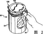
图2显示了从本发明的一容器中移除盖子的一“不用工具的”方法;Figure 2 shows a "tool-less" method of removing a lid from a container of the present invention;
图3显示了从一容器中移除盖子的一第二“不用工具的”方法;Figure 3 shows a second "tool-free" method of removing a lid from a container;
图4显示了一容器的一仰视图;Figure 4 shows a bottom view of a container;
图5显示了一容器的一侧视图;Figure 5 shows a side view of a container;
图6显示了一容器的另一侧视图;Figure 6 shows another side view of a container;
图7显示了一容器倾倒插件的一实施例的一立体图;Figure 7 shows a perspective view of an embodiment of a container pouring insert;
图8显示了容器倾倒插件的一侧视图;Figure 8 shows a side view of the container pouring insert;
图9显示了容器倾倒插件的一俯视图;Figure 9 shows a top view of the container pouring insert;
图10显示了容器倾倒插件的一剖视图;Figure 10 shows a cutaway view of the container pouring insert;
图11显示了另一容器倾倒插件实施例的一俯视图;Figure 11 shows a top view of another container pouring insert embodiment;
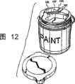
图12显示了一容器倾倒插件的另一实施例;Figure 12 shows another embodiment of a container pouring insert;
图13显示了具有一两片提环型手柄的一实施例的一容器的一立体图;Figure 13 shows a perspective view of a container with an embodiment of a two-piece handle;
图14显示了从一容器中分离的一单片提环型手柄的一实施例的一立体图;Figure 14 shows a perspective view of an embodiment of a one-piece bail-style handle detached from a container;
图15显示了从一容器中分离的一两片提环型手柄的一实施例的一立体图;Figure 15 shows a perspective view of an embodiment of a two-piece bail handle detached from a container;
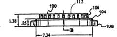
图16显示了根据本发明的一第一实施例的一容器盖子的一侧视图;Figure 16 shows a side view of a container lid according to a first embodiment of the present invention;
图17显示了根据本发明的一第一实施例的一容器盖子的一仰视图;Figure 17 shows a bottom view of a container lid according to a first embodiment of the present invention;
图18显示了根据本发明的一第一实施例的一容器盖子的一剖视图;Figure 18 shows a cross-sectional view of a container lid according to a first embodiment of the present invention;
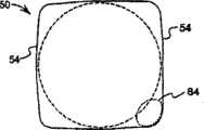
图19显示了与一传统油漆罐相比较的、本发明的容器的覆盖面积;Figure 19 shows the footprint of the container of the present invention compared to a conventional paint can;
图20显示了本敷料器的一容器的一整体手柄的另一实施例;Figure 20 shows another embodiment of an integral handle of a container of the present applicator;
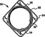
图21显示了本发明的一打开的容器的一俯视图;Figure 21 shows a top view of an opened container of the present invention;
图22显示了在一容器上固定在位的一插件和盖子的一剖视图;Figure 22 shows a cutaway view of an insert and lid secured in place on a container;
图23显示了排列多个容器的一方法;Figure 23 shows a method of arranging multiple containers;
图24显示了一插件相对于容器的其它部分的一较佳的定向;Figure 24 shows a preferred orientation of an insert relative to the rest of the container;
图25显示了具有一开口的盖子的一容器;Figure 25 shows a container with an open lid;
图26和27显示了与本发明的一容器一起使用的附件;Figures 26 and 27 show accessories for use with a container of the present invention;
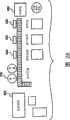
图28显示了用于制造、充填和附加地准备用于装运或储藏的本应用的容器的一制造系统的一示意图;Figure 28 shows a schematic diagram of a manufacturing system for manufacturing, filling and additionally preparing containers for this application for shipping or storage;
图29显示了具有一流体液面指示器的一容器;Figure 29 shows a container with a fluid level indicator;
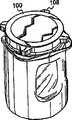
图30显示了具有另一盖子实施例的一容器;Figure 30 shows a container with another lid embodiment;
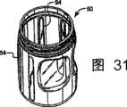
图31显示了具有内肋筋的一容器;Figure 31 shows a container with internal ribs;
图32显示了定位在容器的颈部内的一倾倒插件;Figure 32 shows a pouring insert positioned within the neck of the container;
图33显示了以堆垛构造的两个容器;Figure 33 shows two containers configured in a stack;
图34—37显示了多种另外的容器和盖子构造的实施例;Figures 34-37 show embodiments of various additional container and lid configurations;
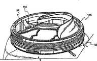
图38显示了根据本发明、用于配合油漆敷料器附件的一盖子组件的一立体图;Figure 38 shows a perspective view of a cap assembly for use with a paint applicator attachment in accordance with the present invention;
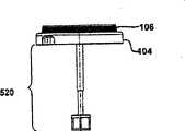
图39显示了用于配合油漆敷料器组件的一盖子组件的一侧视图;Figure 39 shows a side view of a cover assembly for use with a paint applicator assembly;
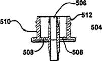
图40显示了用于配合油漆敷料器组件的一盖子组件的一分解图;Figure 40 shows an exploded view of a cover assembly for use with the paint applicator assembly;
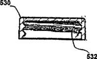
图41显示了用于配合油漆敷料器组件的一盖子组件的一侧剖图;Figure 41 shows a side cutaway view of a cover assembly for use with a paint applicator assembly;
图42显示了根据本发明的一第二实施例的一盖子的一立体图;Figure 42 shows a perspective view of a cover according to a second embodiment of the present invention;
图43显示了根据本发明的一第二实施例的一盖子的一仰视图;Figure 43 shows a bottom view of a lid according to a second embodiment of the present invention;
图44显示了根据本发明的一第二实施例的一盖子的一侧剖图;Figure 44 shows a side sectional view of a cover according to a second embodiment of the present invention;
图45显示了根据本发明的一实施例的一通风组件的一立体图;Figure 45 shows a perspective view of a ventilation assembly according to an embodiment of the present invention;
图46显示了根据本发明的一实施例的一通风组件的一侧视图;Figure 46 shows a side view of a ventilation assembly according to an embodiment of the present invention;
图47显示了根据图45所示的实施例的一通风组件的一侧剖图;Figure 47 shows a side cross-sectional view of a ventilation assembly according to the embodiment shown in Figure 45;
图48显示了根据本发明的一第二实施例的一通风组件的一俯视图;Figure 48 shows a top view of a ventilation assembly according to a second embodiment of the present invention;
图49显示了根据图48所示的实施例的通风组件的一俯视图;Figure 49 shows a top view of the ventilation assembly according to the embodiment shown in Figure 48;
图50显示了与盖子组件一起使用的一帽子的一立体图;以及Figure 50 shows a perspective view of a hat for use with the cap assembly; and
图51显示了与本发明的盖子组件一起使用的一帽子的一侧剖图。Figure 51 shows a cutaway side view of a cap for use with the cap assembly of the present invention.
具体实施方式Detailed ways
应该理解,在附图中所示的元件的分界线代表了分界线的一个例子。本领域普通技术人员应该理解,一个元件可以设计成多个元件,或者多个元件可以设计成一个元件。显示成另一元件的内部部件的一元件可以实施为一外部部件,反之亦然。It should be understood that the dividing lines of elements shown in the drawings represent one example of dividing lines. Those skilled in the art should understand that one element can be designed as multiple elements, or multiple elements can be designed as one element. An element shown as an internal component of another element may be implemented as an external component and vice versa.
此外,在下面的附图和描述中,所有附图和描述都用相同的参考标号来标示相同的零件。附图不是按比例绘制的,为了便于说明,已将某些零件的比例放大。Furthermore, in the following drawings and descriptions, the same reference numerals are used to denote the same parts throughout all the drawings and descriptions. The drawings are not drawn to scale and some features have been exaggerated for illustrative purposes.
参见图1,显示了容器50和盖子100组件的诸部件的一示意图。该组件包括具有一整体手柄84的一容器50、一提环手柄120、一倾倒插件150和具有拉片108的一盖子100。Referring to Figure 1, a schematic view of the components of the
参见图4、5和6,容器包括一本体51、底壁52、侧壁54、一颈部66和一个或多个手柄84。在所示的实施例中,底壁52是正方形的,但在其它实施例中也可以是矩形的或圆形的。本体51是一件式的,较佳地由任何可以吹塑成型的聚合物材料制成,例如高密度聚乙烯(HDPE)或聚丙烯。这些材料的使用以及容器50的设计,可使当容器从一约48英寸或约120cm的高度掉落时受到较小量的损坏,该高度好比是与油漆通常掉落的一等效高度。该损坏的减小就可减少由于装运或其它的损坏造成产品不合消费者需要而退还至生产者的容器的数量。底壁52作为容器50的基座,当放置在一平坦表面上时提供稳定性。底壁52可以包括一凹槽56。如图33所示,凹槽56具有类似于盖子100的形状,从而当多个容器堆叠时,一个容器50的盖子100与一第二容器50的底壁52相配合。Referring to FIGS. 4 , 5 and 6 , the container includes a body 51 ,
本体51的底壁62与容器50的侧壁54整体地形成。参见图1,本体51显示了包括四个侧壁54。侧壁54可以全部或部分地由一透明材料形成,诸如聚对苯二甲酸乙二醇酯(PET)。透明材料允许观察到容器内的液体。图29显示了在手柄84中包括一透明材料的窄带58的一容器50,来允许观察到流体液面。容器50可以附加地包括刻度,该刻度允许量化残留在容器50内的流体液面。The bottom wall 62 of the body 51 is integrally formed with the
侧壁54的数量和形状取决于容器50的整体形状。如图2所示的一圆形容器50包括一单个侧壁54,而如图1所示的一矩形容器50包括四个侧壁54。图1所示的侧壁54具有一平坦的、光滑的表面。可选择地,如图5所示,侧壁54可以稍微被修整并稍微粗糙或有织纹,以便于标签和类似物的敷贴,并简化将侧壁54吹塑成型的方法。在具有多于一个侧壁54的一矩形实施例中,每个侧壁54在一拐角78处与一邻近的侧壁54交汇。与传统的圆柱形油漆罐相比,矩形实施例给附连至侧壁54的标签提供了增加的可见性。这样的增加的可见性可提供销售和市场优点,因为消费者更易于阅读和观察形成在一平坦的容器标签上的材料。The number and shape of
为了增加强度,在所示的实施例中的拐角78处较佳地被弄圆,在堆叠期间当装填的容器受压时,这会是需要的。附加地,当拐角被弄圆时,弄圆的量不能太大以致于减小了容器的需要容积。在要用容器50来替换保存一(1)加仑油漆的一传统的油漆罐之处,该容器要有至少139盎司的容量,这就在流体液面和盖子100之间提供一些顶部空间。在较佳的实施例中,每个拐角78处可弄圆至约0.75英寸(19mm)的半径。The
此外,在图5和6中所示的侧壁54也是凹入的,这样,包括弄圆拐角的容器50的顶部和底部86和88形成水平加强肋90。肋90水平地围绕顶部和底部86和88。此外,在顶部和底部86和88之间可提供一垂直肋92。图5显示了沿着一整体手柄84相对向的拐角的一外突肋。图20显示了在容器50上的许多内突肋94。内突肋94给容器50增加了强度,并通过阻断沿着容器50的侧壁54的流体流以帮助流体混合过程。可将图6的容器实施例中整体手柄84相对向的拐角96修整成具有一较低的型面,从而避免当液体从容器50中倾倒出时成为液体的阻碍和干涉。在本应用的矩形实施例中,每个侧壁54还具有从侧壁54的顶部延伸至侧壁54的底部的一假想的中线“M”。该中线“M”定位成与侧壁54的每个拐角78等距离。当容器50的盖子100螺纹地拧入一密封位置时,盖子100的拉片108可与侧壁54之间或侧壁54的中线“M”之间的拐角78对准,这取决于实施例。Additionally, the
参见图19,较佳地,本应用的容器被定尺寸,由于其基本相等的有效填充容积而易于替换传统的圆柱形金属油漆罐。有效填充容积包括容器的有效填充“覆盖面积”(随宽度和深度而变化)以及容器的有效填充高度,并可与一传统金属油漆罐的覆盖面积和高度相比拟。有效填充容积是有效填充覆盖面积与有效填充高度的乘积。对于将本容器作为一传统技术油漆罐的替代物的制造、操作、储藏和使用等方面,有效填充容积是很重要的。由于具有一基本相等的填充容积,本容器就可经常以传统的机器操作,并可用制造者、零售商和消费者惯常和普遍使用的方式来包装、装填、贴标签、装运、展示、处置和使用。容器50的实施例,与保存一加仑或一夸脱的传统油漆罐以及在欧洲和世界的其它地方为标准的公制罐子的有效填充容积相配。一传统的具有一圆形横截面的一加仑圆柱形油漆罐的尺寸是约7.68英寸的高度和约6.63英寸的直径。传统罐子的圆形横截面可以内切于本应用的矩形容器50实施例的横截面,导致基本相等的有效填充覆盖面积。矩形容器实施例的深度和宽度基本等于传统圆柱形罐的直径,提供四分之一英寸的余量以用于制造公差。矩形容器实施例的等于容器和盖子组件组合的高度的有效填充高度也类似地基本等于传统罐子和盖子的有效填充高度,并有四分之一英寸的余量。因此,例如,尽管容器50及其整体手柄84有非常不同的几何形状,但容器50仍可保存与传统圆柱形金属罐可以保存的量—一加仑—相等量的材料,同时两者中,都在盖子100和容器50内的流体材料之间留出足够的“顶部空间”。有效填充容积也是基本相等的。具有一基本等于一传统罐子的填充容积,本应用的容器50可以易于替换传统罐子。Referring to Figure 19, preferably, the container for this application is sized to readily replace conventional cylindrical metal paint cans due to their substantially equal effective fill volumes. Effective fill volume includes the effective fill "footprint" of the container (which varies with width and depth) and the effective fill height of the container, and is comparable to the footprint and height of a conventional metal paint can. Effective fill volume is the product of effective fill coverage and effective fill height. Effective fill volume is important for the manufacture, handling, storage and use of the container as a replacement for a traditional art paint can. Due to having a substantially equal fill volume, the container can often be handled by conventional machinery and can be packaged, filled, labeled, shipped, displayed, handled and used in the manner customary and commonly used by manufacturers, retailers and consumers . An embodiment of
图1—5和13所示的容器50包括一整体手柄84。整体手柄84可以是容器内的一垂直立柱,并形成在容器50的一拐角78上。整体手柄84可以是中空的或实心的,但较佳地是中空的,以便于容器50内液体的混合。类似于容器50,整体手柄84可以全部或部分透明。手柄84有适当尺寸,来允许不同的消费者都能舒适把握。手柄84大大增加了容器50的整体强度,尤其是对于垂直负荷的整体强度。手柄84被弄成圆截面,以便舒适操作。参见图13,手柄84包括一内部面80,该内部面限定了从一个侧壁54延伸至一个邻近的侧壁54的一空穴的部分。空穴也由从一个侧壁54延伸至一个邻近的侧壁54的一内壁82所形成。所示的内壁82是平面的。The
如图21所示,容器的颈部66限定了一宽口开口,该宽口开口具有一足够大的直径,从而内壁82延伸进入宽口开口的直径。整体手柄84可与一提环形手柄120的一第二手柄一起使用,或作为该第二手柄的替换,该第二手柄将在下面更详细描述。As shown in Figure 21, the
如图6所示,容器50的侧壁54并入一整体颈部66。颈部66包括具有一宽口开口的一垂直部分70。颈部66具有比在其侧壁的容器小的直径。可将在顶部86介于侧壁54和颈部66之间的侧壁54弄圆以作加强,并在侧壁54和颈部66之间产生一平滑的连接。类似地,也将顶部86中的侧壁54的连接处的拐角74弄圆。尽管可被弄圆,但拐角也可以是尖角的,以使容器的容量最大化。如上所述,一个或多个拐角74也可相对于其它侧壁尺寸凹入,以考虑到当油漆流从一容器50或一管口160中倾倒时可适当清除。由于颈部66的直径比容器50的宽度稍小,在颈部66和侧壁54之间提供一水平部分68,跨越了在颈部66的一垂直部分70和侧壁54的顶部之间的距离。此水平部分68的长度,取决于容器50的诸相对侧壁54间的宽度和颈部66在其垂直部分70的直径之间的差异。As shown in FIG. 6 , the
颈部的垂直部分可以包括用于容器50内放置的液体的一实际的或假想的“填充线”。在容器50的一矩形实施例中,对应于128盎司流体的填充线位于比颈部的顶部低一英寸,且较佳地比颈部66的顶部低约0.77英寸。对应于131盎司流体的填充线是产生色彩材料的任何色度所需要的理论上最大的涂料和颜料量,它较佳地是比颈部66的顶部低约0.56英寸。颈部66的垂直部分70较佳地还包括一提环座72。提环座是在颈部66上一致的垂直直径的一部分,一提环型手柄120可以附连至其上。如图22所示,提环座可以通过一凸缘73在其顶侧上镶边。凸缘73具有超过提环座72的一直径,因此,允许提环手柄120迅速越过凸缘73进入在提环座72上的一锁定位置。提环手柄120可以通过手动施加力或通过盖子100螺纹地拧在容器50上的动作来迅速入位。一提环手柄120可如图1和2的实施例绕其座72自由旋转,或者可键入用以在容器本体51上特定对准的座中,如图6所示。在图6、13和16所示的固定的提环手柄实施例中,延伸自提环120的一短片122安装在颈部66中的座72上的一凹槽75内,反之亦然。回过来参见图6,颈部66包括在凸缘73上方的一螺纹的表面76。螺纹表面76可以包括一单个连续的螺纹,来将盖子100固定和密封进入在容器50上的一封闭位置。在较佳的实施例中,螺纹表面76包括一双螺旋线螺纹。双螺旋线螺纹保证了盖子100在一预先确定的位置处开始接合颈部,从而,当盖子完成其在颈部螺纹76上的旋转并紧紧密封时,将盖子100上的拉片108定位在一预先确定的位置。在具有两个拉片108的一盖子100的较佳的实施例中,在密封位置的两个拉片108的预先确定位置是一个与整体手柄84对准、而另一个与整体手柄相对向的一拐角对准,如图13所示。The vertical portion of the neck may comprise an actual or imaginary "fill line" for the liquid placed within the
参见图21,容器50的颈部66的内部可包括许多插座98。插座可以是延伸自颈部66的内表面的突起物。插座98可提供用于放置一插件150的一位置。颈部66还可以包括延伸自其内表面的一个或多个短片99。一个短片99被设计成与一配合凹口154相配合,该配合凹口154形成在插件150中,来帮助定位插件150成如图32所示的一所需定向。具有多于一个短片99的颈部的一实施例会仅仅具有一单个短片99,该短片99有适当尺寸来与在插件上的凹槽154相配合。Referring to FIG. 21 , the interior of the
图7—11显示了一种类型的插件150,该插件可放置在容器50的颈部66内。插件150可通过聚丙烯注射成型来制造。插件150包括围绕外侧的一外壁152,同时插件邻接于颈部66的内表面而在位。外壁152可以将一凹槽154限定于沿其底部在一个位置。如上所述,此凹槽154与颈部66的短片99相配合,从而如图24所示在一所需的位置与插件150对准。7-11 show one type of
回过来参见图7—11,在应用的一实施例中,插件150还包括一管口160。管口160可以形成为延伸穿过插件内部的一部分的一腹板156。腹板156和管口的径向延伸件不超过外壁152的直径。然而,管口160的高度可以在插件外壁152的顶部上方延伸。例如,管口部分从宽口开口径向向上延伸小于所述插件的半径的一段距离。管口160可以是腹板156的内部的一部分172,该部分172是向上展开的。由于展开的部分172向上延伸,它可能变成更垂直,当倾倒容器50内的液体时,这有助于形成一较佳的流线轮廓。管口160的展开部分172的顶部从前至后稍稍成角度,从而,当盖子螺纹地接合容器50的颈部66上时,可减小刮擦盖子100下面的管口160插件的几率。Referring back to FIGS. 7-11 , in one embodiment of the application, the
管口160在水平横截面中具有一弓形形状。图9显示了管口160在水平横截面中具有一较佳的“U”形状。在应用的一实施例中,管口的尖端174到在管口的两个后缘176之间的一假想线的距离是约2—3英寸或2.4英寸,而在尖端174管口160的曲率半径是约1英寸或约2.5cm。管口160可以具有约2英寸的一狭小直径,来限制油漆不期望的大流量,并提供一平滑的倾倒流。管口160可以具有圆形的后边缘176来提供高强度,并可使与浸入容器50的一刷子的干涉最小化。尤其,诸如4英寸宽或10cm宽的一大刷子应可易于穿过管口160或其它插件150而接近容器50并进入容器内部。如图7—11所示,管口160在其内表面158上从顶部延伸至底部,可将之修整而提供一所需的形状,从而有助于油漆的倾倒。管口160在其尖端174具有约0.03英寸(0.76mm)的一小厚度,来防止终止的油漆流的额外滴落。较小的厚度很难注射成型。如图10所示,管口160在其外表面上从顶部延伸至底部,可将之修整而提供在倾倒过程之后用于将油漆或其它涂料流回容器50的内部的一所需形状。在这点上,管口160连同腹板内的一回流槽164一起工作。The
回流槽164从管口160的底部延伸至插件150的内壁151。回流槽164可以完全地围绕管口160并在管口160之外和之下。回流槽164可以具有一曲线的底部。在腹板156内,回流槽164可以从腹板156的前面的一较高位置向后面的一较低位置倾斜,来保证在倾倒之后回流槽164内的液体返回至容器内部。The
在一插件的另一实施例中,如图12所示,插件150可以包括一平坦的上表面166,该上表面166限定了一多功能开口。开口的一向前倾倒部分起到一管口160的作用。此管口160实施例并不从插件上表面166向上延伸。开口的一横向部分起到刷子进入通道的作用。开口横向部分的平坦后壁167可用于从一浸入的刷子擦去一部分油漆。开口的一后部分起到一搅拌棒刮擦器162的作用。开口的后部分非常狭窄,并与允许刷子通过的部分横切地定位。In another embodiment of an insert, as shown in FIG. 12, insert 150 may include a planar upper surface 166 that defines a multifunctional opening. A poured forward portion of the opening functions as a
参见图13,一手柄,也称为一提环或提环型手柄120,可用于提起容器50。提环120可以通过一注射成型工艺由诸如聚乙烯之类的材料来制成。提环120包括一弓形元件124,该弓形元件124可以直接附连至容器50的颈部66或附连至一箍环126。箍环126和弓形元件124可以由一单片聚合物或多片聚合物形成。在一单片实施例中,在图14中所示,弓形元件124在一非提起的状态,放置成通常与箍环126的主平面相平行。单片实施例可以由中密度聚乙烯(MDPE)制成。当将提环提起时,弓形元件124在接近与箍环126的接头处转动,并变成通常垂直于箍环126。在一多片实施例中,箍环126可以由高密度聚乙烯制成,它外接于容器50的颈部66并邻接于如上所述的提环座72。Referring to FIG. 13 , a handle, also known as a loop or loop-
在一多片实施例中,在图13和15中所示,一窝和盘接头128可以将弓形元件124结合至箍环126。弓形元件124可以具有一连续变化的横截面,并为了舒适而可由低密度聚乙烯制成。弓形元件124尽管是整体形成的,但可以包括多个不同形状的分段130。这些分段130可以是曲线的和/或直线的。弓形元件124可以包括一中心分段132,该中心分段132可以是平直的或曲线的。在一较佳的实施例中,中心分段132比其余的分段130更宽更厚。也可将中心分段132的下面弄圆,以提供手提容器50时的舒适。当中心分段132是弓形的时,提环手柄120伸出时容器50悬挂自一物体或由一使用者携带,易于相对于物体使它自己居中,来给悬挂的容器50提供稳定性。中心分段132也可以相对于提环手柄120的其余部分尺寸特大,从而提供手提时的舒适。In a multi-piece embodiment, shown in FIGS. 13 and 15 , a socket and disk joint 128 may join the
提环120的弓形元件124可以自由摆动,或可以栓牢在容器的颈部66的边缘上或容器盖子100的一拉片108上。这种栓牢的特征可防止提环120不想要的摆动。同样在图13中所示的应用的一单独的实施例中,提环120的弓形元件124可以通过在盖子100上的一个或多个拉片108来锁定在较低的位置,或可以自由地摆动而越过和围绕拉片108。可将提环120的窝和盘128成形来提供沿一摆动路径的一较佳放置点,例如弓形元件直接垂直提起的位置。弓形元件124和箍环126可以是两个单独的片,易于在盘和窝接头处咬合在一起。The
可将提环120较佳地定尺寸,为在容器的一矩形实施例内具有不超过从侧壁到侧壁的宽度的一最大宽度。类似地,可将提环120较佳地定尺寸,为在容器的一圆柱形实施例中具有不超过侧壁的直径的一最大宽度。The
参见图16—18,可以显示一盖子100,它在容器50的颈部66上接合螺纹76。盖子100可以通过一注射成型工艺来成形,并由诸如聚丙烯之类的材料来制成。盖子100可具有如图2所示的一基本平直的表面,或者具有带有图16—18中所示的突起握肋的一阶梯式顶面。在图16—18的实施例中,形成一下部104和一上部106。上部106给插件的管口160提供了余隙。为了在堆叠中的稳定性,如前所述,上部的106的侧面与一邻近的容器50的底壁52相配合。上部106可以具有小于下部104的一直径。下部104包括从一外表面径向向外延伸的多个拉片108。下部104可以包括内螺纹102,该内螺纹102与在容器50的颈部66上的双螺旋线螺纹76连通和配合。如前所述,这些螺纹102可以是一双螺旋线,以使一旦盖子100在容器颈部66上紧密或密封接合时能精确定位。盖子100的较佳实施例包括两个拉片108。另一实施例包括如图30和35—36所示的四个拉片108。拉片108可以绕盖子的周围均匀间隔。Referring to FIGS. 16-18 , a
图2显示了使用盖子100上的拉片108来手动打开容器。通过提供可以手动打开的带有一盖子100的容器50,无需工具,而在传统的金属罐中通常是需要工具的,且在打开期间还具有损坏油漆罐的趋向。因此,本应用的容器50和盖子100组件提供了“不用工具的”开口。在一封闭位置,在容器的盖子上的一拉片108可以在握住容器50的整体手柄84的使用者的拇指可到达范围内。当盖子在一密封位置时,拉片108也在矩形容器的侧壁的宽度内,尽管在盖子100的施加或去除期间,拉片108可以超出侧壁的宽度。通过沿不同方向掠动他或她的拇指,使用者可以施加力至拉片108的任一侧,这样可以打开或密封地闭合容器盖子100。当整体手柄84由使用者的左手或右手握住时,此方法是同样有效的。当需要附加的力时,如图3所示,使用者的双手可以放置在容器50的相对的拐角上。所需的拐角与盖子100上的拉片108对准。通过使用者的一个手上的拇指和另一个手的手指,施加力至拉片108来去除盖子或将盖子密封就位。在一所需的实施例中,通过0.5圈和0.75圈之间的旋转或旋转至可去除的位置,可将盖子100从一密封位置移开。FIG. 2 shows the use of the
如图22所示,在上部106的底部与下部104的顶部之间延伸的一水平座110给一可插入的弹性或柔性密封件62提供了一放置座和密封接头,密封件62可以用于本应用的相同实施例。密封件可以包括靠在一平直表面上的插件150。如图16所示,上部的外表面可以包括多个肋112。这些肋112可使盖子更易于握住。上部106的较小的直径给具有较小手的使用者提供了一把握空间。肋112也在制造中提供了脱模优点。盖子100的顶部114可以包括一凹处来接纳一标签。As shown in FIG. 22, a
参见图20,显示了用于握住本应用的容器50的手柄84的另一个变型,它包括在容器的邻近侧壁54上的手柄凹槽250。手柄凹槽250并不彼此一起形成前述的其它手柄实施例中所存在的空穴。手柄凹槽250可以包括背脊或其它类型的纹理,来增加握紧性能。如图所示,手柄凹槽250可以具有高度超过宽度的一矩形形状。Referring to Fig. 20, another variation of the
参见图21,显示了整体手柄84相对于宽口开口的定向。在直径方面,宽口开口是容器两相对侧壁之间距离的至少80%,较佳地是至少83%。限定整体手柄84的空穴部分的内壁82与宽口开口垂直对准,从而延伸入宽口开口。Referring to Figure 21, the orientation of the
参见图22,在容器的颈部66和插件150之间显示了一箍缩锁定机构的一详细剖视图。插件150包括带有一钩端180的一悬臂部分178。插件150还包括邻近于悬臂部分178的一斜面部分182。悬臂部分178连同插件150的斜面部分182,起到将插件150锁进和围绕容器颈部的位置的作用。在操作中,插件150首先从颈部66分离,可以放置在由颈部66限定的开口内。插件150的一锥形表面184的一部分与颈部66的顶部的一部分接触。当用力使插件150向下时,插件150的锥形表面184沿颈部66的顶部的一部分滑动,直到到达插件150的斜面部分182为止。同时,插件150的斜面部分182到达颈部66的内斜面部分79和插件150的悬臂部分178,且悬臂部分178的钩端180封盖颈部66的顶部。然后插件150锁定在位,直到它受力而去除为止。Referring to Figure 22, a detailed cross-sectional view of a pinch lock mechanism is shown between the
盖子100有助于形成密封,它可防止容器50内的油漆或其它涂料的溢出或干燥。为了帮助形成密封,盖子100可以包括一内环和侧密封面。内环116从盖子100的上部106的内侧向下延伸。侧密封面可以位于盖子的螺纹部分的上方。当盖子100螺纹地拧到颈部66上时,内环116和侧密封面一起挤压插件150。侧密封面118邻接悬臂部分178的钩端180,而内环116邻接插件150的顶部。
参见图23,显示了一种用于堆叠本应用的容器50的方法。该方法包括在诸如一货盘的一支持物上或在一盒子内放置四个或更多个容器50。容器被放置成它们的整体手柄84向支持物的外部定向。此定向可提供抵抗对容器组的侧面碰撞的强度,以及有助于堆叠的、在外部上的强度。然后,一第二支持物和一第二组至少四个容器50可以以相同的定向放置在第一组盒装容器的顶部上的一盒子内。在实践中,可将四个盒装容器的三附加层添加至一单个货盘。在实践中,多至五层容器的一第二货盘可以放置在第一货盘的顶部上。容器手柄的定向允许单独的容器易于从由多个货盘或组所形成的一堆垛中移除。Referring to Figure 23, a method for stacking
参见图28,本应用的容器可在紧凑地区的生产设备中或在并排的生产设备中制造和装配。在一较佳的方法中,一制造机器,典型的是一吹塑成型机300,位于紧接于油漆混合和填充机310。这样布局的一个好处是,大型容器零件不需要在设备之间储藏或装运。在一种制造方法中,将一成型设备置于直接紧邻一油漆配制设备,而将成型的容器零件从前到后传输穿过一墙中的通道。诸如贴标签机320、盖子装配机330和涂敷机器、装配机340和码堆机350之类的最终制备机也可位于紧接处。涂敷和装配操作可以任何顺序来完成。Referring to Figure 28, containers for this application can be manufactured and assembled in compact area production facilities or in side-by-side production facilities. In a preferred method, a manufacturing machine, typically a
图24显示了装配有一较佳对准的插件150的一容器。插件150的管口160相对于整体手柄84而定向。将提环手柄120定向成,当弓形元件124放下时,中心分段132可以放置在整体手柄84正上方。如图13和37所示,在盖子100上的拉片108定向成,当盖子密封在容器上时,一拉片108在包括整体手柄84的容器拐角的正上方。因此,所示实施例的所有方面都适当对准,以便容易装运以及使消费者容易使用容器和盖子组件。Figure 24 shows a container fitted with an
参见图25、26和27,显示了带有包括一孔400和通风口410的容器盖子100的本应用的一实施例。当例如一喷漆机的一附件或辅助装置420要使用容器50内的液体时,可以正常堵塞或打开孔400。通风口410也可正常关闭,但要在孔400未堵塞时打开。通风口410允许空气进入容器50,以取代抽取的液体,例如在油漆或其它操作期间在真空下通过一附件420来完成。Referring to Figures 25, 26 and 27, an embodiment of this application with a
在图38—51中显示了图25—27所示构思的一变型。此实施例包括一改进的盖子和抽气机组件,用于从容器中通过一敷料器装置抽取油漆。参见图38—44,提供了一改进的容器盖子100’。改进的容器盖子100’与上述的关于图16—18的盖子在结构和功能上类似。然而,在此实施例中,盖子100’在其中心具有一凹处500。凹处500从盖子的上部106延伸至盖子的下部104,并形成穿过其中的一开口。在一有用的实施例中,凹处开口500比盖子的上部106宽,而比盖子的下部窄。在本发明的一实施例中,一凸缘501围绕凹处开口的底部向内延伸。A variation on the concept shown in Figures 25-27 is shown in Figures 38-51. This embodiment includes an improved lid and aspirator assembly for extracting paint from the container through an applicator device. Referring to Figures 38-44, an improved container lid 100' is provided. The improved container lid 100' is similar in structure and function to the lid described above with respect to Figures 16-18. However, in this embodiment, the cover 100' has a
改进的盖子/抽气机组件还包括一喷嘴装置502。喷嘴装置502构造成安装和固定在凹处500内。在图40和45—48所示的实施例中,喷嘴组件502是基本圆柱形的。喷嘴组件502包括一基座504、一向上延伸的壁510、一填充管506和一个或多个通风孔508。如图45—47所示,一圆柱形壁510从基座向上延伸。在一实施例中,基座504的直径至少略大于向上延伸的圆柱形壁510的直径,从而基座504的边缘向上延伸至少一短距离而越过壁510。喷嘴组件502及其部件可以由适用于在此描述的容器和盖子以及多种油漆敷料器的任何材料来构成,包括多种金属和塑料材料。The improved cover/aspirator assembly also includes a
在一实施例中,喷嘴组件502定位于所述凹处中,从而基座504的外边缘放置在凸缘501上。喷嘴组件可以通过任何已知的方法固定在盖子凹处500内。在一实施例中,使用超声波焊接来固定喷嘴502至盖子100’。在另一实施例中,基座504可以包括围绕其周边的螺纹。在此实施例中,凹处500的下部的内表面会具有构造成与喷嘴基座504上的螺纹配合的螺纹。In one embodiment, the
一填充管506延伸穿过基座504。填充管506在两端开口,并从基座504向上和向下延伸。在所示的实施例中,填充管506从基座504延伸与圆柱壁510大约相等的距离。同样,填充管506从基座504向下延伸,从而当盖子和抽气机组件定位在一油漆容器上时,例如如图3所示,填充管506将向下延伸至少一短距离而进入容器颈部66和/或本体51。A
基座板包括一个或多个通风口508。在一实施例中,基座板包括如图48和49所示的多个通风孔。如下所述,通风孔508允许空气进入容器,以通过诸如一油漆敷料器之类的一辅助装置来取代从容器中提取的一定量的液体。The base plate includes one or
一吸入管路520从盖子100’向下延伸。吸入管路520包括填充管506。当盖子/抽气机组件定位于一容器的顶部上时,吸入管路520延伸进入容器。在一有用的实施例中,吸入管路520构造成延伸足够远而进入油漆容器,从而当一辅助装置用于从容器中提取油漆时,吸入管路520能够从容器中去除基本所有的油漆。A
吸入管路可以由填充管的一向下延伸件组成,它足够长而到达一容器的底部或接近底部。在一实施例中,吸入管路520由包括一吸入管514的多个部件组成。吸入管514较佳地由诸如PVC塑料管之类的塑料组成。吸入管514可以一直向下延伸至容器的底部。然而,一些敷料器装置可以具有小出口开口,并且假如干燥油漆的颗粒或任何其它固体通过而进入敷料器装置则可能变得堵塞。为了解决此问题,一过滤器518可以附连至吸入管514,从而在任何大的固体颗粒到达敷料器装置之前,从油漆中去除它。最后,一吸入总管516可以附连至喷雾过滤器518的下部,并用来便于从容器中提取油漆。The suction line may consist of a downward extension of the fill tube which is long enough to reach or near the bottom of a container. In one embodiment, the
如图45—47所示,喷嘴装置502的圆柱形壁510包括一螺纹区域512。螺纹区域512可以包括一单个连续的螺纹,来将帽530固定和密封而进入通风/分配组件502上的一封闭位置。在另一实施例中,螺纹面512可以包括一双螺旋线螺纹。The
帽530在图38、40和50—51中显示。将帽定尺寸,来安装在喷嘴装置502的上方,堵塞填充管506和通风孔508的两个开口,并密封容器以便储藏。帽530包括内螺纹532,该内螺纹532与喷嘴装置502的圆柱形壁上的螺纹512相连通和配合。帽530的外表面可以包括多个突起的握肋534,来帮助旋紧和从喷嘴502去除帽530。
凹处500相对于喷嘴组件502的直径应该是这样:向外延伸越过圆柱形壁510的基座504的边缘可以接合凹处的边缘,同时可使帽530易于固定至喷嘴502并从喷嘴502去除。The diameter of the
在使用中,能够从一容器中通过一管子提取油漆的任何油漆敷料器都可用于连接图38—51中所示的盖子/抽气机组件。例如,如第4,732,503号所述的一油漆敷料器具有可以附连至填充管506的一吸入导管。在此应用中,敷料器中的一柱塞装置从储藏器/手柄中向外拉出,造成在储藏器中的一真空压力。真空压力导致容器中的油漆被吸入储藏器。当从容器中将油漆去除时,通风口允许空气进入容器,来取代提取的液体。In use, any paint applicator capable of extracting paint from a container through a tube may be used in connection with the cap/aspirator assembly shown in Figures 38-51. For example, a paint applicator as described in Ser. No. 4,732,503 has a suction conduit that can be attached to the
在另一实施例中,可以使用一泵来从容器中虹吸油漆至一敷料器装置。例如,在美国专利第4,175,300中公开的装置,一泵可以附连至填充管506。泵将穿过吸入管路520和填充管506而抽吸。油漆由泵通过与一敷料器连通的一导管路而排出。In another embodiment, a pump may be used to siphon paint from a container to an applicator device. For example, in the device disclosed in US Patent No. 4,175,300, a pump can be attached to the
尽管上面给出了特定的实施例,应该理解,在图25—27和/或38—51中所示的和在此所述的装置可用于多种已知的敷料器和喷雾器,包括但不限于内馈的油漆滚筒或刷子、动力滚筒或刷子、无气喷雾器、杯喷枪型喷雾器、隔膜泵喷雾器、活塞泵喷雾器、空气压缩喷枪喷雾器、高容量/低压力(HVLP)喷雾器以及其它类似装置。Although specific examples have been given above, it should be understood that the devices shown in FIGS. 25-27 and/or 38-51 and described herein can be used with a variety of known applicators and sprayers, including but not Internally fed paint rollers or brushes, powered rollers or brushes, airless sprayers, cup gun sprayers, diaphragm pump sprayers, piston pump sprayers, compressed air spray gun sprayers, high volume/low pressure (HVLP) sprayers, and other similar devices.
尽管本发明由其实施例的描述来说明,且尽管已经相当详细地描述了实施例,但申请者并不想将所附的权利要求书的范围约束或以任何方式限制于这样的细节。对于本领域普通技术人员来说,附加的优点和修正是显而易见的。因此,本发明以其较宽的方面,并不限于特定的细节、典型的装置以及所示和所述的说明性的例子。因此,可从这些细节作出变更,而不脱离申请者总的发明原理的精神或范围。While the invention is illustrated by the description of its embodiments, and although the embodiments have been described in some detail, the applicant does not intend to restrict or in any way limit the scope of the appended claims to such details. Additional advantages and modifications will readily appear to those skilled in the art. Therefore, the invention in its broader aspects is not limited to the specific details, typical apparatus and illustrative examples shown and described. Accordingly, departures may be made from such details without departing from the spirit or scope of applicant's general inventive concept.
Claims (8)
Applications Claiming Priority (3)
| Application Number | Priority Date | Filing Date | Title |
|---|---|---|---|
| US55786004P | 2004-03-31 | 2004-03-31 | |
| US60/557,860 | 2004-03-31 | ||
| US60/603,226 | 2004-08-20 |
Publications (2)
| Publication Number | Publication Date |
|---|---|
| CN1972756A CN1972756A (en) | 2007-05-30 |
| CN100490992Ctrue CN100490992C (en) | 2009-05-27 |
Family
ID=38113116
Family Applications (1)
| Application Number | Title | Priority Date | Filing Date |
|---|---|---|---|
| CNB2005800141846AExpired - LifetimeCN100490992C (en) | 2004-03-31 | 2005-03-31 | Apparatus for extracting paint from containers, container lids and assemblies of containers and lids |
Country Status (1)
| Country | Link |
|---|---|
| CN (1) | CN100490992C (en) |
Families Citing this family (3)
| Publication number | Priority date | Publication date | Assignee | Title |
|---|---|---|---|---|
| CN101850691B (en)* | 2009-11-30 | 2012-09-19 | 浙江奥利达气动工具股份有限公司 | Paint storing spray gun kettle |
| CN104014463A (en)* | 2013-11-28 | 2014-09-03 | 昆山御广峰机械有限公司 | Novel manual glue coating machine |
| CN106836750B (en)* | 2015-12-03 | 2019-06-28 | 尼尔雷特有限公司 | It is installed on the cock of coating machine |
- 2005
- 2005-03-31CNCNB2005800141846Apatent/CN100490992C/ennot_activeExpired - Lifetime
Also Published As
| Publication number | Publication date |
|---|---|
| CN1972756A (en) | 2007-05-30 |
Similar Documents
| Publication | Publication Date | Title |
|---|---|---|
| US20060273092A1 (en) | Container and Lid Assembly | |
| US6983862B2 (en) | Container and lid assembly | |
| US7040509B2 (en) | Container for liquids, including sealing mechanisms | |
| US7036693B2 (en) | Paint container | |
| US7988005B2 (en) | Storage system | |
| US7216779B2 (en) | Sealing mechanisms for use in liquid-storage containers | |
| US8123066B2 (en) | Container | |
| US8381932B2 (en) | Storage system | |
| US7175051B2 (en) | Container for liquids, including sealing mechanisms | |
| EP1689652B1 (en) | Container sealing system | |
| CN100490992C (en) | Apparatus for extracting paint from containers, container lids and assemblies of containers and lids |
Legal Events
| Date | Code | Title | Description |
|---|---|---|---|
| C06 | Publication | ||
| PB01 | Publication | ||
| C10 | Entry into substantive examination | ||
| SE01 | Entry into force of request for substantive examination | ||
| C14 | Grant of patent or utility model | ||
| GR01 | Patent grant | ||
| TR01 | Transfer of patent right | ||
| TR01 | Transfer of patent right | Effective date of registration:20190202 Address after:Ohio, USA Patentee after:Xuanwei Investment Management Co.,Ltd. Address before:Ohio, USA Patentee before:Xuanwei Headquarters Co. Effective date of registration:20190202 Address after:Ohio, USA Patentee after:Xuanwei Headquarters Co. Address before:Ohio, USA Patentee before:THE SHERWIN-WILLIAMS CO. | |
| CX01 | Expiry of patent term | ||
| CX01 | Expiry of patent term | Granted publication date:20090527 |