CN100489433C - Heat pipe device utilizing natural cold energy and application thereof - Google Patents
Heat pipe device utilizing natural cold energy and application thereofDownload PDFInfo
- Publication number
- CN100489433C CN100489433CCNB2004100754630ACN200410075463ACN100489433CCN 100489433 CCN100489433 CCN 100489433CCN B2004100754630 ACNB2004100754630 ACN B2004100754630ACN 200410075463 ACN200410075463 ACN 200410075463ACN 100489433 CCN100489433 CCN 100489433C
- Authority
- CN
- China
- Prior art keywords
- heat
- pipe
- energy storage
- storage device
- energy
- Prior art date
- Legal status (The legal status is an assumption and is not a legal conclusion. Google has not performed a legal analysis and makes no representation as to the accuracy of the status listed.)
- Expired - Fee Related
Links
- 238000004146energy storageMethods0.000claimsabstractdescription103
- 238000001704evaporationMethods0.000claimsabstractdescription75
- 230000008020evaporationEffects0.000claimsabstractdescription43
- 238000001816coolingMethods0.000claimsabstractdescription22
- 238000004378air conditioningMethods0.000claimsabstractdescription18
- 230000000630rising effectEffects0.000claimsabstractdescription17
- 230000005494condensationEffects0.000claimsabstractdescription16
- 238000009833condensationMethods0.000claimsabstractdescription16
- 238000005338heat storageMethods0.000claimsdescription18
- 239000000463materialSubstances0.000claimsdescription16
- 238000010438heat treatmentMethods0.000claimsdescription11
- 239000012774insulation materialSubstances0.000claimsdescription10
- 238000005057refrigerationMethods0.000claimsdescription5
- 230000005611electricityEffects0.000claimsdescription4
- 238000005485electric heatingMethods0.000claimsdescription3
- 239000002440industrial wasteSubstances0.000claimsdescription3
- 239000007787solidSubstances0.000claimsdescription2
- 238000004891communicationMethods0.000claims1
- 230000007613environmental effectEffects0.000abstractdescription2
- 239000003570airSubstances0.000description23
- XLYOFNOQVPJJNP-UHFFFAOYSA-NwaterSubstancesOXLYOFNOQVPJJNP-UHFFFAOYSA-N0.000description13
- 238000000034methodMethods0.000description12
- 239000002689soilSubstances0.000description10
- 238000012546transferMethods0.000description9
- 238000010586diagramMethods0.000description8
- 238000004321preservationMethods0.000description8
- 230000001174ascending effectEffects0.000description7
- 239000012267brineSubstances0.000description5
- 239000011810insulating materialSubstances0.000description5
- HPALAKNZSZLMCH-UHFFFAOYSA-Msodium;chloride;hydrateChemical compoundO.[Na+].[Cl-]HPALAKNZSZLMCH-UHFFFAOYSA-M0.000description5
- 239000011435rockSubstances0.000description4
- 239000007790solid phaseSubstances0.000description4
- 230000007547defectEffects0.000description3
- 238000007710freezingMethods0.000description3
- 230000008014freezingEffects0.000description3
- 238000001802infusionMethods0.000description3
- 229910000831SteelInorganic materials0.000description2
- 238000005553drillingMethods0.000description2
- 238000005265energy consumptionMethods0.000description2
- 239000003344environmental pollutantSubstances0.000description2
- 239000005431greenhouse gasSubstances0.000description2
- 230000017525heat dissipationEffects0.000description2
- 238000009434installationMethods0.000description2
- 239000007788liquidSubstances0.000description2
- 239000011159matrix materialSubstances0.000description2
- 239000012071phaseSubstances0.000description2
- 231100000719pollutantToxicity0.000description2
- 239000010959steelSubstances0.000description2
- 239000012080ambient airSubstances0.000description1
- 238000009412basement excavationMethods0.000description1
- 238000010276constructionMethods0.000description1
- 239000000110cooling liquidSubstances0.000description1
- 239000012530fluidSubstances0.000description1
- 239000007789gasSubstances0.000description1
- 238000002347injectionMethods0.000description1
- 239000007924injectionSubstances0.000description1
- 238000003780insertionMethods0.000description1
- 230000037431insertionEffects0.000description1
- 238000009413insulationMethods0.000description1
- 230000002452interceptive effectEffects0.000description1
- 238000012423maintenanceMethods0.000description1
- 230000001681protective effectEffects0.000description1
- 239000003507refrigerantSubstances0.000description1
- 230000003068static effectEffects0.000description1
Images


Classifications
- F—MECHANICAL ENGINEERING; LIGHTING; HEATING; WEAPONS; BLASTING
- F25—REFRIGERATION OR COOLING; COMBINED HEATING AND REFRIGERATION SYSTEMS; HEAT PUMP SYSTEMS; MANUFACTURE OR STORAGE OF ICE; LIQUEFACTION SOLIDIFICATION OF GASES
- F25B—REFRIGERATION MACHINES, PLANTS OR SYSTEMS; COMBINED HEATING AND REFRIGERATION SYSTEMS; HEAT PUMP SYSTEMS
- F25B30/00—Heat pumps
- F25B30/06—Heat pumps characterised by the source of low potential heat
- F—MECHANICAL ENGINEERING; LIGHTING; HEATING; WEAPONS; BLASTING
- F24—HEATING; RANGES; VENTILATING
- F24F—AIR-CONDITIONING; AIR-HUMIDIFICATION; VENTILATION; USE OF AIR CURRENTS FOR SCREENING
- F24F5/00—Air-conditioning systems or apparatus not covered by F24F1/00 or F24F3/00, e.g. using solar heat or combined with household units such as an oven or water heater
- F24F5/0046—Air-conditioning systems or apparatus not covered by F24F1/00 or F24F3/00, e.g. using solar heat or combined with household units such as an oven or water heater using natural energy, e.g. solar energy, energy from the ground
- F—MECHANICAL ENGINEERING; LIGHTING; HEATING; WEAPONS; BLASTING
- F24—HEATING; RANGES; VENTILATING
- F24T—GEOTHERMAL COLLECTORS; GEOTHERMAL SYSTEMS
- F24T10/00—Geothermal collectors
- F24T10/10—Geothermal collectors with circulation of working fluids through underground channels, the working fluids not coming into direct contact with the ground
- F24T10/13—Geothermal collectors with circulation of working fluids through underground channels, the working fluids not coming into direct contact with the ground using tube assemblies suitable for insertion into boreholes in the ground, e.g. geothermal probes
- F24T10/15—Geothermal collectors with circulation of working fluids through underground channels, the working fluids not coming into direct contact with the ground using tube assemblies suitable for insertion into boreholes in the ground, e.g. geothermal probes using bent tubes; using tubes assembled with connectors or with return headers
- F—MECHANICAL ENGINEERING; LIGHTING; HEATING; WEAPONS; BLASTING
- F24—HEATING; RANGES; VENTILATING
- F24T—GEOTHERMAL COLLECTORS; GEOTHERMAL SYSTEMS
- F24T10/00—Geothermal collectors
- F24T10/30—Geothermal collectors using underground reservoirs for accumulating working fluids or intermediate fluids
- F—MECHANICAL ENGINEERING; LIGHTING; HEATING; WEAPONS; BLASTING
- F24—HEATING; RANGES; VENTILATING
- F24T—GEOTHERMAL COLLECTORS; GEOTHERMAL SYSTEMS
- F24T10/00—Geothermal collectors
- F24T10/40—Geothermal collectors operated without external energy sources, e.g. using thermosiphonic circulation or heat pipes
- F—MECHANICAL ENGINEERING; LIGHTING; HEATING; WEAPONS; BLASTING
- F28—HEAT EXCHANGE IN GENERAL
- F28D—HEAT-EXCHANGE APPARATUS, NOT PROVIDED FOR IN ANOTHER SUBCLASS, IN WHICH THE HEAT-EXCHANGE MEDIA DO NOT COME INTO DIRECT CONTACT
- F28D15/00—Heat-exchange apparatus with the intermediate heat-transfer medium in closed tubes passing into or through the conduit walls ; Heat-exchange apparatus employing intermediate heat-transfer medium or bodies
- F28D15/02—Heat-exchange apparatus with the intermediate heat-transfer medium in closed tubes passing into or through the conduit walls ; Heat-exchange apparatus employing intermediate heat-transfer medium or bodies in which the medium condenses and evaporates, e.g. heat pipes
- F28D15/0266—Heat-exchange apparatus with the intermediate heat-transfer medium in closed tubes passing into or through the conduit walls ; Heat-exchange apparatus employing intermediate heat-transfer medium or bodies in which the medium condenses and evaporates, e.g. heat pipes with separate evaporating and condensing chambers connected by at least one conduit; Loop-type heat pipes; with multiple or common evaporating or condensing chambers
- F—MECHANICAL ENGINEERING; LIGHTING; HEATING; WEAPONS; BLASTING
- F24—HEATING; RANGES; VENTILATING
- F24F—AIR-CONDITIONING; AIR-HUMIDIFICATION; VENTILATION; USE OF AIR CURRENTS FOR SCREENING
- F24F5/00—Air-conditioning systems or apparatus not covered by F24F1/00 or F24F3/00, e.g. using solar heat or combined with household units such as an oven or water heater
- F24F5/0007—Air-conditioning systems or apparatus not covered by F24F1/00 or F24F3/00, e.g. using solar heat or combined with household units such as an oven or water heater cooling apparatus specially adapted for use in air-conditioning
- F24F5/0017—Air-conditioning systems or apparatus not covered by F24F1/00 or F24F3/00, e.g. using solar heat or combined with household units such as an oven or water heater cooling apparatus specially adapted for use in air-conditioning using cold storage bodies, e.g. ice
- F24F2005/0025—Air-conditioning systems or apparatus not covered by F24F1/00 or F24F3/00, e.g. using solar heat or combined with household units such as an oven or water heater cooling apparatus specially adapted for use in air-conditioning using cold storage bodies, e.g. ice using heat exchange fluid storage tanks
- F—MECHANICAL ENGINEERING; LIGHTING; HEATING; WEAPONS; BLASTING
- F24—HEATING; RANGES; VENTILATING
- F24F—AIR-CONDITIONING; AIR-HUMIDIFICATION; VENTILATION; USE OF AIR CURRENTS FOR SCREENING
- F24F5/00—Air-conditioning systems or apparatus not covered by F24F1/00 or F24F3/00, e.g. using solar heat or combined with household units such as an oven or water heater
- F24F5/0046—Air-conditioning systems or apparatus not covered by F24F1/00 or F24F3/00, e.g. using solar heat or combined with household units such as an oven or water heater using natural energy, e.g. solar energy, energy from the ground
- F24F2005/0057—Air-conditioning systems or apparatus not covered by F24F1/00 or F24F3/00, e.g. using solar heat or combined with household units such as an oven or water heater using natural energy, e.g. solar energy, energy from the ground receiving heat-exchange fluid from a closed circuit in the ground
- F—MECHANICAL ENGINEERING; LIGHTING; HEATING; WEAPONS; BLASTING
- F24—HEATING; RANGES; VENTILATING
- F24F—AIR-CONDITIONING; AIR-HUMIDIFICATION; VENTILATION; USE OF AIR CURRENTS FOR SCREENING
- F24F5/00—Air-conditioning systems or apparatus not covered by F24F1/00 or F24F3/00, e.g. using solar heat or combined with household units such as an oven or water heater
- F24F5/0007—Air-conditioning systems or apparatus not covered by F24F1/00 or F24F3/00, e.g. using solar heat or combined with household units such as an oven or water heater cooling apparatus specially adapted for use in air-conditioning
- F24F5/0017—Air-conditioning systems or apparatus not covered by F24F1/00 or F24F3/00, e.g. using solar heat or combined with household units such as an oven or water heater cooling apparatus specially adapted for use in air-conditioning using cold storage bodies, e.g. ice
- F24F5/0021—Air-conditioning systems or apparatus not covered by F24F1/00 or F24F3/00, e.g. using solar heat or combined with household units such as an oven or water heater cooling apparatus specially adapted for use in air-conditioning using cold storage bodies, e.g. ice using phase change material [PCM] for storage
- Y—GENERAL TAGGING OF NEW TECHNOLOGICAL DEVELOPMENTS; GENERAL TAGGING OF CROSS-SECTIONAL TECHNOLOGIES SPANNING OVER SEVERAL SECTIONS OF THE IPC; TECHNICAL SUBJECTS COVERED BY FORMER USPC CROSS-REFERENCE ART COLLECTIONS [XRACs] AND DIGESTS
- Y02—TECHNOLOGIES OR APPLICATIONS FOR MITIGATION OR ADAPTATION AGAINST CLIMATE CHANGE
- Y02B—CLIMATE CHANGE MITIGATION TECHNOLOGIES RELATED TO BUILDINGS, e.g. HOUSING, HOUSE APPLIANCES OR RELATED END-USER APPLICATIONS
- Y02B10/00—Integration of renewable energy sources in buildings
- Y02B10/20—Solar thermal
- Y—GENERAL TAGGING OF NEW TECHNOLOGICAL DEVELOPMENTS; GENERAL TAGGING OF CROSS-SECTIONAL TECHNOLOGIES SPANNING OVER SEVERAL SECTIONS OF THE IPC; TECHNICAL SUBJECTS COVERED BY FORMER USPC CROSS-REFERENCE ART COLLECTIONS [XRACs] AND DIGESTS
- Y02—TECHNOLOGIES OR APPLICATIONS FOR MITIGATION OR ADAPTATION AGAINST CLIMATE CHANGE
- Y02B—CLIMATE CHANGE MITIGATION TECHNOLOGIES RELATED TO BUILDINGS, e.g. HOUSING, HOUSE APPLIANCES OR RELATED END-USER APPLICATIONS
- Y02B10/00—Integration of renewable energy sources in buildings
- Y02B10/40—Geothermal heat-pumps
- Y—GENERAL TAGGING OF NEW TECHNOLOGICAL DEVELOPMENTS; GENERAL TAGGING OF CROSS-SECTIONAL TECHNOLOGIES SPANNING OVER SEVERAL SECTIONS OF THE IPC; TECHNICAL SUBJECTS COVERED BY FORMER USPC CROSS-REFERENCE ART COLLECTIONS [XRACs] AND DIGESTS
- Y02—TECHNOLOGIES OR APPLICATIONS FOR MITIGATION OR ADAPTATION AGAINST CLIMATE CHANGE
- Y02E—REDUCTION OF GREENHOUSE GAS [GHG] EMISSIONS, RELATED TO ENERGY GENERATION, TRANSMISSION OR DISTRIBUTION
- Y02E10/00—Energy generation through renewable energy sources
- Y02E10/10—Geothermal energy
Landscapes
- Engineering & Computer Science (AREA)
- Life Sciences & Earth Sciences (AREA)
- Mechanical Engineering (AREA)
- General Engineering & Computer Science (AREA)
- Sustainable Development (AREA)
- Sustainable Energy (AREA)
- Chemical & Material Sciences (AREA)
- Combustion & Propulsion (AREA)
- Physics & Mathematics (AREA)
- Thermal Sciences (AREA)
- General Life Sciences & Earth Sciences (AREA)
- Other Air-Conditioning Systems (AREA)
Abstract
Translated fromChinese
Description
Translated fromChinese技术领域technical field
本发明属于制冷系统、加热和制冷的联合系统、蓄冷、蓄热设备及其配件,尤其涉及一种利用自然冷能和环保热能的空调系统。The invention belongs to a refrigeration system, a combined system of heating and refrigeration, cold storage, heat storage equipment and accessories thereof, in particular to an air conditioning system utilizing natural cold energy and environmentally friendly heat energy.
背景技术Background technique
现有的制冷、蓄能设备及空调大多采用压缩机使工质通过压缩——膨胀循环制冷;其具有商品能耗大,运行成本高,运行不稳定,维护操作复杂,使用有害介质,有直接和间接的温室气体及其它污染物排放,存在噪声污染,对电力依赖性强,对电力峰值负荷影响较大等缺点。Most of the existing refrigeration, energy storage equipment and air conditioners use compressors to make the working medium go through compression-expansion cycle refrigeration; it has the advantages of high energy consumption, high operating costs, unstable operation, complicated maintenance operations, and the use of harmful media, which has direct And indirect emissions of greenhouse gases and other pollutants, there are disadvantages such as noise pollution, strong dependence on electricity, and greater impact on electricity peak loads.
申请号为91101569.8的中国发明专利申请公开说明书公开了一种由风管、载冷剂、输液箱及贮冷体组成的供冷装置。其风管通过载冷剂输液箱与载冷剂进行热交换,载冷剂输液箱通过连通钢管中的载冷剂与贮冷体进行热交换。冬季利用风管中冷热气体形成的静压力差和风速自动输入大气中的冷量,并通过贮冷体中水的相变潜热贮存,夏季制冷时,通过供冷水管及载冷剂与贮能体循环进行热交换,释放冷量。The Chinese Invention Patent Application Publication No. 91101569.8 discloses a cooling device consisting of an air duct, a brine, an infusion tank and a cold storage body. The air pipe conducts heat exchange with the brine through the brine infusion tank, and the brine infusion tank communicates with the brine in the steel pipe to exchange heat with the cold storage body. In winter, the static pressure difference and wind speed formed by the cold and hot gas in the air pipe are used to automatically input the cooling capacity in the atmosphere, and it is stored through the phase change latent heat of the water in the cooling body. It can exchange heat through body circulation and release cold energy.
这种蓄能设备利用了冬天大气中的自然冷能,达到了节能的目的,避免了温室气体及其它污染物排放,但存在下列缺陷:(1)冷量的输入、输出通过大量的商品载冷剂完成,至少冷量输出需强制循环,自然对流效率低;(2)冷量的输入、输出均通过二次换热,降低换热效率,增大冷量损失;(3)风管无法消除传导、对流冷量损失;(4)风管会造成堵塞;(5)空气与钢管壁换热效率很低,实际工程中需大量排管及支撑件;(6)满足保温、防胀、防渗,同时又高效换热的自然冷能贮存器造价昂贵,难以实施。This energy storage device utilizes the natural cold energy in the atmosphere in winter, achieves the purpose of energy saving, and avoids the emission of greenhouse gases and other pollutants, but has the following defects: (1) The input and output of cold energy are carried by a large number of commodities. When the refrigerant is completed, at least the output of cooling capacity needs to be forced to circulate, and the efficiency of natural convection is low; (2) The input and output of cooling capacity are both through secondary heat exchange, which reduces the heat exchange efficiency and increases the loss of cooling capacity; (3) The air duct cannot Eliminate conduction and convection cooling loss; (4) The air duct will cause blockage; (5) The heat exchange efficiency between the air and the steel pipe wall is very low, and a large number of pipes and supports are needed in the actual project; (6) It meets the requirements of heat preservation, anti-expansion, The anti-seepage and high-efficiency heat exchange natural cold energy storage are expensive and difficult to implement.
现有蓄冷装置也有使用图1所示的单体热管作为导冷元件的,但这种单体热管蓄能设备仍有下列缺陷:(1)管内上升蒸汽和下降冷却液体处于同一管道之中,相互之间存在循环阻力,有相互换热现象,从而影响传导功率,因此单支热管导冷功率小;(2)相同传导功率条件下造价相对高;(3)安装受角度限制;(4)不能进行开启和关闭或调节功率大小从而实现有序冻结。Existing cold storage devices also use the single heat pipe shown in Figure 1 as the cold conduction element, but this single heat pipe energy storage device still has the following defects: (1) the ascending steam in the pipe and the descending cooling liquid are in the same pipe, There is circulation resistance between each other, and there is mutual heat exchange phenomenon, which affects the conduction power, so the cooling power of a single heat pipe is small; (2) The cost is relatively high under the same conduction power condition; (3) The installation is limited by the angle; (4) There is no ability to turn it on and off or adjust the power level to achieve an orderly freeze.
发明内容Contents of the invention
本发明旨在克服上述缺陷,其目的之一在于提供一种利用自然冷能和环保热能的自动传导热能的热管装置。The present invention aims to overcome the above-mentioned defects, and one of its objects is to provide a heat pipe device that automatically conducts heat energy using natural cooling energy and environmentally friendly heat energy.
本发明目的之二在于提供一种存储自然冷能和环保热能的蓄能装置。The second object of the present invention is to provide an energy storage device for storing natural cold energy and environmentally friendly heat energy.
本发明目的之三在于提供一种利用自然冷能和环保热能的空调装置。The third object of the present invention is to provide an air conditioner utilizing natural cold energy and environmentally friendly heat energy.
本发明目的之四在于提供一种利用自然冷能和环保热能的建筑体系。The fourth object of the present invention is to provide a building system utilizing natural cooling energy and environmentally friendly thermal energy.
本发明的利用自然冷能或环保热能的热管装置是这样实现的,它包括蒸发部、冷凝部、上升管和回流管,其中蒸发部低于或等于冷凝部,蒸发部的上端与冷凝部的上端通过上升管连接,冷凝部的下端与蒸发部的下端通过回流管连接,构成热管回路,其中冷凝部由多根冷凝管并联构成,并在冷凝部的冷凝管外设有翅片,其特征在于蒸发部置于地表下蓄能介质深处,蒸发部由单根蒸发管构成,蒸发部与回流管连通呈U型,或蒸发部为一盲管,上升管与盲管的上部管口连通,回流管插入盲管腔内中下部,上升管采用导热系数低的材料制成,或者上升管壁外设有保温层。The heat pipe device utilizing natural cold energy or environmental protection heat energy of the present invention is realized in this way, and it comprises evaporating part, condensing part, ascending pipe and return pipe, wherein evaporating part is lower than or equal to condensing part, the upper end of evaporating part and condensing part The upper end is connected by a rising pipe, and the lower end of the condensing part is connected with the lower end of the evaporating part through a return pipe to form a heat pipe circuit. The evaporation part is placed deep in the energy storage medium under the surface. The evaporation part is composed of a single evaporation tube, and the evaporation part is connected with the return pipe in a U shape, or the evaporation part is a blind tube, and the rising tube is connected with the upper nozzle of the dead tube. , the return pipe is inserted into the middle and lower part of the blind pipe cavity, and the ascending pipe is made of a material with low thermal conductivity, or an insulating layer is provided outside the wall of the ascending pipe.
回流管采用导热系数低的材料制成,或者回流管壁外设有保温层。热管回路上设置至少一个阀门。The return pipe is made of a material with low thermal conductivity, or an insulating layer is provided outside the return pipe wall. At least one valve is arranged on the heat pipe circuit.
蒸发部至少部分蒸发管之间或者蒸发管腔室内设置动力循环管,动力循环管的进出口位于蒸发部之外。A power circulation pipe is arranged between at least part of the evaporation tubes of the evaporation part or in the chamber of the evaporation tube, and the inlet and outlet of the power circulation tube are located outside the evaporation part.
本发明的蓄能装置是这样实现的,它由蓄能介质和热管装置组成,其中热管装置的蒸发部位于蓄能介质中,蓄能介质为天然岩土或者其他相变体。The energy storage device of the present invention is realized in such a way that it is composed of an energy storage medium and a heat pipe device, wherein the evaporation part of the heat pipe device is located in the energy storage medium, and the energy storage medium is natural rock and soil or other phase change bodies.
蓄能介质外设置保温材料;在蓄能介质中设置动力循环管路,该动力循环管路均匀地分布于蓄能介质中。An insulating material is arranged outside the energy storage medium; a power circulation pipeline is arranged in the energy storage medium, and the power circulation pipeline is evenly distributed in the energy storage medium.
本发明的空调装置是这样实现的,它包括蓄能装置和与其发生热交换的终端回路,该终端回路包括空调末端,空调末端为风机盘管、暖气片或地盘管。The air conditioner of the present invention is realized in this way, it includes an energy storage device and a terminal circuit for heat exchange with it, the terminal circuit includes an air conditioner terminal, and the air conditioner terminal is a fan coil unit, a radiator or a ground coil unit.
在终端回路与蓄能装置之间设置换热器,而且蓄能装置与换热器发生热交换,换热器与终端回路发生热交换。A heat exchanger is arranged between the terminal circuit and the energy storage device, and the energy storage device exchanges heat with the heat exchanger, and the heat exchanger exchanges heat with the terminal circuit.
终端回路与蓄能装置或换热器之间设置热泵,热泵的初级冷源或初级热源输入端与蓄能装置或换热器发生热交换,热泵的输出端与终端回路发生热交换。A heat pump is installed between the terminal loop and the energy storage device or heat exchanger, the primary cold source or primary heat source input end of the heat pump exchanges heat with the energy storage device or heat exchanger, and the output end of the heat pump exchanges heat with the terminal loop.
蓄能装置之一为蓄冷装置,热管冷凝部位于大气之中,设置在热管蒸发部或蓄能装置中的动力循环管路与终端回路连通。换热器设置在动力循环管路与终端回路之间。动力循环管路与采用峰谷电或风能制冷的制冷机输出端相连。One of the energy storage devices is a cold storage device, the condensing part of the heat pipe is located in the atmosphere, and the power circulation pipeline arranged in the evaporating part of the heat pipe or the energy storage device communicates with the terminal circuit. A heat exchanger is provided between the power cycle line and the final circuit. The power cycle pipeline is connected to the output end of the refrigerator using peak and valley electricity or wind energy cooling.
蓄能装置之二为蓄热装置,热管装置的冷凝部与终端回路连通。热管装置的冷凝部位于热交器之中。设置在热管蒸发部或蓄能装置中的动力循环管路与供热热源相连。供热热源为工业余热、太阳能集热装置、峰谷电制热的热泵,或利用风能制热的热泵。The second energy storage device is a heat storage device, and the condensation part of the heat pipe device communicates with the terminal circuit. The condensation part of the heat pipe device is located in the heat exchanger. The power circulation pipeline arranged in the evaporating part of the heat pipe or the energy storage device is connected with the heat supply heat source. The heating source is industrial waste heat, solar heat collector, heat pump for peak and valley electric heating, or heat pump for heating by wind energy.
本发明的建筑体系是这样实现的,它包括空调装置和建筑物,其中空调装置的空调末端位于建筑物内,蓄能装置中的蓄能介质位于地下。The building system of the present invention is realized in that it includes an air-conditioning device and a building, wherein the air-conditioning end of the air-conditioning device is located in the building, and the energy storage medium in the energy storage device is located underground.
其中之一,蓄能装置为蓄冷装置,热管装置的蒸发部随蓄能介质位于地表下,热管装置的冷凝部位于地上建筑物之外大气中,蓄冷装置或热管装置中的动力循环管与空调末段直接相连,或经过换热器或热泵与空调末段发生热交换。One of them, the energy storage device is a cold storage device, the evaporation part of the heat pipe device is located under the ground along with the energy storage medium, the condensation part of the heat pipe device is located in the atmosphere outside the building on the ground, and the power circulation pipe and the air conditioner in the cold storage device or heat pipe device The end stage is directly connected, or undergoes heat exchange with the end stage of the air conditioner through a heat exchanger or heat pump.
其中之二,蓄能装置为蓄热装置,热管装置的动力循环管与太待储热源连通,热管装置的蒸发部与空调末段直接相连,或通过换热器或热泵与空调末段发生热交换。The second one is that the energy storage device is a heat storage device, the power circulation pipe of the heat pipe device is connected with the thermal storage source, and the evaporation part of the heat pipe device is directly connected with the end stage of the air conditioner, or generates heat with the end stage of the air conditioner through a heat exchanger or a heat pump. exchange.
其中之三,蓄能装置包括蓄冷装置和蓄热装置,其共同与终端回路连接,供冷时终端回路与蓄冷装置发生热交换,供热时终端回路与蓄热装置发生热交换。The third one is that the energy storage device includes a cold storage device and a heat storage device, which are connected to the terminal circuit. The terminal circuit exchanges heat with the cold storage device during cooling, and the terminal circuit exchanges heat with the heat storage device during heating.
附图说明Description of drawings
图1为现有技术中热管装置的结构示意图;Fig. 1 is the structural representation of heat pipe device in the prior art;
图2为本发明中热管装置的结构示意图之一;Fig. 2 is one of structural representations of heat pipe device in the present invention;
图3为本发明中热管装置的结构示意图之二;Fig. 3 is the second structural diagram of the heat pipe device in the present invention;
图4为本发明中热管装置的结构示意图之三;Fig. 4 is the third structural diagram of the heat pipe device in the present invention;
图5为本发明中热管装置的结构示意图之四;Fig. 5 is the fourth schematic view of the structure of the heat pipe device in the present invention;
图6为本发明中热管装置的结构示意图之五;Fig. 6 is the fifth structural diagram of the heat pipe device in the present invention;
图7为本发明中蓄能装置的结构示意图之一;Fig. 7 is one of the structural representations of the energy storage device in the present invention;
图8为本发明中蓄能装置的结构示意图之二;Fig. 8 is the second structural diagram of the energy storage device in the present invention;
图9为图8的A向视图;Fig. 9 is the A direction view of Fig. 8;
图10为本发明中蓄能装置的结构示意图之三;Fig. 10 is the third structural diagram of the energy storage device in the present invention;
图11为本发明中空调装置及建筑体系的结构示意图之一;Figure 11 is one of the structural schematic diagrams of the air-conditioning device and the building system in the present invention;
图12为本发明中空调装置及建筑体系的结构示意图之二;Fig. 12 is the second structural diagram of the air-conditioning device and the building system in the present invention;
图13为本发明中空调装置及建筑体系的结构示意图之三。Fig. 13 is the third schematic diagram of the structure of the air-conditioning device and the building system in the present invention.
具体实施方式Detailed ways
热管装置的实施例1
参见图2,本发明所述的热管装置10a,它包括蒸发部1、冷凝部2、上升管3和回流管4,其中蒸发部由多根蒸发管并联构成,冷凝部由多根冷凝管并联构成,蒸发部1低于冷凝部2,蒸发部的上端与冷凝部的上端通过上升管3连接,冷凝部的下端与蒸发部的下端通过回流管4连接,构成热管回路。上升管3和回流管4上设有保温材料,当然也可以是采用导热系数低的材料制成;冷凝部的冷凝管外设有翅片;蒸发部1的蒸发管内充有的低沸点工质;热管回路上设置阀门5以便调节控制换热功率及方便灌注工质,其中上升管和回流管上分别设置一个阀门,上升管顶端设置一个阀门。Referring to Fig. 2, the
该热管装置的工作原理是:蒸发部1的低沸点工质通过管壁从蒸发部外界吸热后蒸发,蒸汽延上升管3上升,进入冷凝部2,向冷凝部外界放热后凝结,冷凝后的液体通过下降管4重新进入蒸发部1,如此完成换热循环。只要蒸发部1外界温度高于冷凝部2的外界温度,上述循环即可维持,将蒸发部外界的热不断地传向冷凝部外界;否则,传热过程自动停止,从而实现向上单向导热;而向上单向导热的过程同时就是向下单向导冷过程。The working principle of the heat pipe device is: the low-boiling-point working medium in the evaporating
与图1所示的现有技术相比,本热管的特殊结构可以使蒸发介质在热管装置中单向循环传输,上升的蒸汽和下降的冷凝介质分别行走于上升管和下降管中,互不阻扰,互不换热,介质的循环方向与向上传热和向下传冷循环方向一致,传导效率极高。Compared with the prior art shown in Figure 1, the special structure of the heat pipe can make the evaporating medium unidirectionally circulated in the heat pipe device, and the ascending steam and descending condensing medium walk in the ascending pipe and descending pipe respectively, independent of each other. Interference, no heat exchange, the circulation direction of the medium is consistent with the upward heat transfer and downward cooling cycle, and the conduction efficiency is extremely high.
热管装置的实施例2
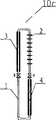
参见图3,热管装置10b,相对实施例1而言,其区别在于热管装置10b的蒸发部由单根蒸发管构成,与回流管4连通呈U型,上升管3和回流管4上设有保温材料;这种结构的好处是便于将蒸发部放置于蓄冷体深处。这种结构既有单体热管易于深井埋管的施工便利,又有分体热管的高效传热性能。Referring to Fig. 3, the
热管装置的实施例3
参见图4,热管装置10c,相对实施例2而言,其区别在于热管装置10c的冷凝部2由单根冷凝管构成,与上升管4连通呈倒U型,上升管3和回流管4上设有保温材料;这种结构的好处是便于将冷凝部放置于介质深处。这种结构可以实现长距离热量传输,同时不受传输方向影响。Referring to Fig. 4, the heat pipe device 10c is different from the
热管装置的实施例4
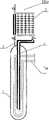
参见图5,热管装置10d,相对实施例1而言,其区别在于蒸发部1为一盲管,上升管2与盲管的上管口连通,回流管4插入盲管腔内下部,上升管3和回流管4上设有保温材料;盲管腔内充有低沸点工质6。Referring to Fig. 5, the
与前述实施例相比,蒸发部1的低沸点工质通过管壁从蒸发部外界吸热后蒸发,蒸汽延上升管3上升,进入冷凝部2,向冷凝部外界放热后凝结,冷凝后的液体通过下降管4重新进入蒸发部盲管底部中心,如此完成换热循环。Compared with the previous embodiment, the low-boiling-point working medium in the evaporating
与图1所示的现有直插式热管相比,虽然蒸发部同为圆管,但本实施例的特殊结构可以使蒸发介质在热管装置中单向循环传输,上升的蒸汽和下降的冷凝介质分别行走于上升管和下降管中,互不阻扰,互不换热,介质的循环方向与向上传热和向下传冷循环方向一致,传导效率极高。Compared with the existing in-line heat pipe shown in Figure 1, although the evaporating part is also a circular pipe, the special structure of this embodiment can make the evaporating medium circulate in one direction in the heat pipe device, and the rising steam and descending condensation The medium travels in the ascending pipe and the descending pipe respectively, without interfering with each other, without mutual heat exchange, the circulation direction of the medium is consistent with the upward heat transfer and downward cold transfer cycle, and the conduction efficiency is extremely high.
热管装置的实施例5
参见图6,热管装置10e,相对实施例4而言,其区别在于蒸发部1的盲管内设置动力循环管7a,动力循环管7a的进出口位于蒸发部1之外;上升管3和回流管4上设有保温材料。Referring to Fig. 6, the
与前述实施例相比,前述实施例虽可实现向上单向导热和向下单向导冷,但不可反向传导,本实施例由于集成有动力循环管7b,可以实现任意方向的冷热传导。Compared with the previous embodiment, although the previous embodiment can realize upward unidirectional heat conduction and downward unidirectional cooling conduction, but not reverse conduction, this embodiment can realize cold and heat conduction in any direction due to the integrated
蓄能装置的实施例1
参见图7,蓄能装置由热管装置10a和蓄能介质组成,蓄能介质为水或其它液固相变材料11a,热管装置多个同时设置,大致均匀地设置在蓄能介质11a之中,其中热管装置的蒸发部1位于蓄能介质11中,在蓄能介质外设置壳体12,壳体外表面设有保温材料13,壳体12是全封闭的,保温材料13可以是全封闭或者部份封闭的;冷凝部2设置在蓄能介质11和保温材料12之外,在蓄能介质中设置动力循环管路7b,该动力循环管路7b大致均匀地设置在热管装置10的蒸发管之间。Referring to Fig. 7, the energy storage device is composed of a
该装置可以实现下述四种功能:The device can realize the following four functions:
蓄冷:参见热管装置的实施例1,其工作原理是,在环境气温低于蓄能介质,例如水的温度时,热管循环自动启动,将水中的热量传向环境大气,水温逐渐下降,当降到水的冰点0℃时,水体沿热管蒸发管壁结冰,随着上述过程的继续,沿蒸发管壁形成的冰柱逐渐沿径向生长,由此实现有序结冰。冻结过程所产生的体积膨胀由尚未冻结的柔性水体吸收;只要蒸发管间距小于蒸发管与壳体之间的最小距离,则蒸发管之间的水体优先结冰,在水体完全结冰之前可将上升管上的阀门单独关闭或与下降管上的阀门同时关闭,主动切断热管循环,防止冰体冻胀破坏壳体,从而实现防止冻胀目的。Cold storage: refer to
释冷:通过设置于蓄能介质当中的动力循环管路内部的介质循环或直接将冰与水组成的蓄能介质中的水进行循环,即可将所蓄的冷能释放到换热装置或直接释放到冷能使用末端,如空调风机盘管。Cooling release: the stored cold energy can be released to the heat exchange device or It is directly released to the end of cold energy use, such as air-conditioning fan coil.
蓄热:在上升阀门和下降阀门关闭状态下,通过动力循环管路将各种热源产生的热能通过显热或潜热形式蓄积到本蓄能装置。Heat storage: When the rising valve and the falling valve are closed, the heat energy generated by various heat sources is stored in the energy storage device in the form of sensible heat or latent heat through the power circulation pipeline.
释热:在上升阀门和下降阀门开启状态下,所蓄热能可以通过热管自动传到冷凝部,将热能释放到与冷凝部相连的换热装置或直接释放到热能使用末端。Heat release: When the rising valve and falling valve are open, the stored heat energy can be automatically transferred to the condensing part through the heat pipe, and the heat energy is released to the heat exchange device connected to the condensing part or directly to the end of the heat energy use.
蓄能装置的实施例2
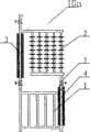
参见图8,蓄能装置由热管装置10b和蓄能介质组成,蓄能介质为固体相变材料或掺有固体相变材料的土壤和砾石11b,热管装置多个同时设置,大致均匀地设置在蓄能介质之中,其中热管装置的蒸发部1位于蓄能介质中,在蓄能介质外设置保温材料13,保温材料13是全封闭的;冷凝部2设置在蓄能介质和保温材料13之外,在蓄能介质中设置动力循环管路7b,该动力循环管路7b大致均匀地设置在热管装置10b的蒸发管之间。Referring to Fig. 8, the energy storage device is composed of a
相对实施例1而言,由于蓄冷介质为固体相变材料,因此可以省去壳体,热管装置的蒸发部为U型管式热管装置10b,在固体蓄能介质中钻孔后可以将热管直接插入,易于安装;为便于安装,还可将U型管设置于圆形保护套管之中。Compared with
参见图9,为了增大热管冷凝部与空气的换热功率,在热管冷凝部周围设置诱导挡风板14,这样可以提高热管冷凝部局部的风速,从而提高热管的传热效率。Referring to Fig. 9, in order to increase the heat exchange power between the heat pipe condensing part and the air, an induced windshield 14 is arranged around the heat pipe condensing part, which can increase the local wind speed of the heat pipe condensing part, thereby improving the heat transfer efficiency of the heat pipe.
蓄能装置的实施例3
参见图10,相对实施例2而言,蓄能介质为土壤和岩石11c,在蓄能介质的周边和顶面设置保温材料13,热管装置为10e。Referring to Fig. 10, as compared to Example 2, the energy storage medium is soil and
相对实施例1而言,由于蓄冷介质为土壤和岩石,底部不易设置保温材料,也不易布置10a型热管装置,但非常适合布置热管装置10e,在土壤和岩石中钻孔后可以将热管直接插入,易于安装。Compared with Example 1, since the cold storage medium is soil and rocks, it is not easy to install insulation materials at the bottom, and it is not easy to arrange 10a-type heat pipe devices, but it is very suitable for arranging
如果蓄冷装置的体积足够大,例如边长大于100米时,蓄热体的表面散热面积相对于其体积较小,可以不用周边的保温层13,可以采用较便宜的保温材料代之。If the volume of the cold storage device is large enough, such as when the side length is greater than 100 meters, the surface heat dissipation area of the heat storage body is relatively small relative to its volume, and the surrounding
空调装置及建筑体系实施例1Example 1 of air-conditioning device and building system
参见图11,空调装置包括蓄能装置和终端回路,该终端回路包括空调末端,空调末端为风机盘管30,其位于建筑物内;蓄能装置为蓄冷装置,蓄能介质为自然土壤11c,在其中钻深井孔,井孔呈矩阵状分布,尤以蜂窝状分布效率最高,井孔中采用10e型热管装置,蓄能介质周围和顶部设有保温材料,上升管3和回流管4外部也设有保温材料,热管装置10e的蒸发部随蓄能介质位于地表下,热管装置的冷凝部2位于地表外环境大气中。Referring to Fig. 11, the air conditioner includes an energy storage device and a terminal circuit, the terminal circuit includes an air conditioner end, the air conditioner end is a
在风机盘管30与蓄能装置之间设置换热器31,可以在一个小区集中设置一个,或每栋建筑物设置一个,设置在热管蒸发部中的动力循环管路7b相互并联后与换热器进行热交换,动力循环管路7设有循环泵32,动力循环管路外部也设有保温材料,换热器31与空调末端30进行热交换。A heat exchanger 31 is arranged between the
这种结构的好处:施工过程不用开挖和回填,降低工程造价。蓄冷是无商品能耗自动完成;释冷只需循环泵耗能。The advantage of this structure is that there is no need for excavation and backfilling during the construction process, which reduces the cost of the project. Cold storage is automatically completed without commodity energy consumption; cooling only needs the energy consumed by the circulating pump.
其工作原理是:冬天环境气温低于蓄能介质温度时,热管将蓄能介质中的热能自动传入环境大气,使蓄能介质冷却,直至作为蓄能介质的自然土壤冻结,以显热及潜热方式蓄存大量的冷能;夏天通过动力循环提能量,通过换热过程或直接输入空调末端。Its working principle is: when the ambient temperature is lower than the temperature of the energy storage medium in winter, the heat pipe will automatically transmit the heat energy in the energy storage medium to the ambient atmosphere, cooling the energy storage medium until the natural soil as the energy storage medium freezes, and the sensible heat and The latent heat method stores a large amount of cold energy; in summer, the energy is raised through the power cycle, through the heat exchange process or directly input into the air conditioner terminal.
空调装置及建筑体系实施例2Example 2 of air-conditioning device and building system
参见图12,相对实施例1而言,蓄能装置为蓄热装置,蓄能介质仍为自然土壤11c,其中钻深井孔,井孔呈矩阵状分布,尤以蜂窝状分布效率最高,井孔中采用10e型热管装置,蓄能介质顶部设有保温材料,周围不设保温材料,上升管3和回流管4外部也设有保温材料,热管装置10e的蒸发部随蓄能介质位于地表下,热管装置的冷凝部2位于换热器中,冷凝部不设翅片管。Referring to Fig. 12, compared with
在风机盘管30与蓄能装置之间设置换热器31,设置在热管蒸发部中的动力循环管路7b相互并联后与换热器进行热交换,动力循环管路7b设有循环泵32,动力循环管路外部也设有保温材料,换热器31与空调末端30进行热交换。A heat exchanger 31 is arranged between the
夏天或秋天,设置在热管蒸发部或蓄能装置中的动力循环管路7b与供热热源太阳能集热装置33通过循环泵及循环管路相连;将热能直接通过热管蒸发部传入蓄能介质;向蓄能介质输入热量时阀门关闭。冬天,将所蓄热能通过热管冷凝部输入换热器或直接输入散热末端热,该过程自动完成,无须强制循环,此时开启上升管及回流管上的阀门。In summer or autumn, the
由于蓄能体巨大,所以热量散失很少,蓄热效率很高。当然,供热热源除了太阳能集热装置,也可以为工业余热、峰谷电制热的热泵,或利用风能制热的热泵。Due to the huge energy storage body, there is little heat loss and the heat storage efficiency is very high. Of course, in addition to solar heat collectors, the heating source can also be industrial waste heat, heat pumps for peak and valley electric heating, or heat pumps using wind energy for heating.
空调装置及建筑体系实施例3Example 3 of air-conditioning device and building system
参见图13,相对实施例1和实施例2而言,本实施例为两者的结合,其中蓄能装置包括蓄冷装置和蓄热装置,热管装置和土壤或水等蓄冷介质所组成的蓄能装置共同形成冷岛,热管装置和土壤或水等蓄热介质所组成的蓄能装置共同形成热岛,而冷岛和热岛双方共用一套终端回路为建筑物供冷或供热,三者的连接处设置转向阀34。Referring to Figure 13, compared to
蓄冷装置蓄冷过程通过热管自动完成,无需动力;与终端回路的换热则通过动力循环完成。蓄热装置蓄热过程通过动力循环完成;与终端回路的换热则通过热管自动完成,无需动力。The cold storage process of the cold storage device is automatically completed through the heat pipe without power; the heat exchange with the terminal circuit is completed through the power cycle. The heat storage process of the heat storage device is completed through the power cycle; the heat exchange with the terminal circuit is automatically completed through the heat pipe without power.
所蓄热能或冷能,与空调末端的换热,可以通过热管冷凝端或动力循环管路完成,也可以通过换热器或热泵完成。当通过热泵完成时,供冷时热泵的冷凝段与蓄冷装置的动力循环管路相连并进行热交换,供热时热泵的蒸发段与蓄热装置的热管蒸发部相连并进行热交换。The heat exchange between the stored heat or cold energy and the end of the air conditioner can be done through the condensing end of the heat pipe or the power cycle pipeline, or through a heat exchanger or a heat pump. When it is completed by the heat pump, the condensation section of the heat pump is connected to the power cycle pipeline of the cold storage device for heat exchange during cooling, and the evaporation section of the heat pump is connected to the heat pipe evaporation part of the heat storage device for heat exchange during heating.
Claims (21)
Translated fromChinesePriority Applications (3)
| Application Number | Priority Date | Filing Date | Title |
|---|---|---|---|
| CNB2004100754630ACN100489433C (en) | 2004-12-17 | 2004-12-17 | Heat pipe device utilizing natural cold energy and application thereof |
| US11/721,725US8567482B2 (en) | 2004-12-17 | 2005-12-16 | Heat tube device utilizing cold energy and application thereof |
| PCT/CN2005/002218WO2006063532A1 (en) | 2004-12-17 | 2005-12-16 | A heat tube device utilizing cold energy and application thereof |
Applications Claiming Priority (1)
| Application Number | Priority Date | Filing Date | Title |
|---|---|---|---|
| CNB2004100754630ACN100489433C (en) | 2004-12-17 | 2004-12-17 | Heat pipe device utilizing natural cold energy and application thereof |
Publications (2)
| Publication Number | Publication Date |
|---|---|
| CN1789877A CN1789877A (en) | 2006-06-21 |
| CN100489433Ctrue CN100489433C (en) | 2009-05-20 |
Family
ID=36587547
Family Applications (1)
| Application Number | Title | Priority Date | Filing Date |
|---|---|---|---|
| CNB2004100754630AExpired - Fee RelatedCN100489433C (en) | 2004-12-17 | 2004-12-17 | Heat pipe device utilizing natural cold energy and application thereof |
Country Status (3)
| Country | Link |
|---|---|
| US (1) | US8567482B2 (en) |
| CN (1) | CN100489433C (en) |
| WO (1) | WO2006063532A1 (en) |
Cited By (2)
| Publication number | Priority date | Publication date | Assignee | Title |
|---|---|---|---|---|
| CN102519075A (en)* | 2011-11-18 | 2012-06-27 | 孙有芳 | Heat island type solar natural air conditioning and heating system |
| RU2787067C1 (en)* | 2021-03-25 | 2022-12-28 | Северно-Западный институт экологии и природных ресурсов Академии наук Китая | Device for heating ground base and ground base including it |
Families Citing this family (64)
| Publication number | Priority date | Publication date | Assignee | Title |
|---|---|---|---|---|
| DE102007062402A1 (en)* | 2007-12-20 | 2009-06-25 | Hans-Ulrich Karsch | Geothermal energy utilization system installing method for building, involves connecting energy transfer points with heat pumps associated with buildings, respectively, and introducing heat exchanger medium into closed cycle |
| SE535370C2 (en) | 2009-08-03 | 2012-07-10 | Skanska Sverige Ab | Device and method for storing thermal energy |
| US9103603B2 (en)* | 2009-10-28 | 2015-08-11 | Tai-Her Yang | Thermal conductive cylinder installed with U-type core piping and loop piping |
| US9587890B2 (en)* | 2009-11-05 | 2017-03-07 | Tai-Her Yang | Vertical fluid heat exchanger installed within natural thermal energy body |
| CN101832673B (en)* | 2010-01-27 | 2012-05-23 | 龚智勇 | Method and device for conducting and recycling subterranean heat with production casings |
| WO2012007216A2 (en)* | 2010-07-12 | 2012-01-19 | Siemens Aktiengesellschaft | Thermal energy storage and recovery with a heat exchanger arrangement having an extended thermal interaction region |
| WO2012060912A1 (en)* | 2010-11-04 | 2012-05-10 | Geoenergy Enterprises, Llc. | Geothermal column |
| WO2012060913A1 (en)* | 2010-11-04 | 2012-05-10 | Geoenergy Enterprises, Llc. | Geothermal system |
| WO2012064387A1 (en)* | 2010-11-08 | 2012-05-18 | Geoenergy Enterprises, Llc | Method of heating/cooling structure using geothermal system |
| CN102538523A (en)* | 2010-12-17 | 2012-07-04 | 益科博能源科技(上海)有限公司 | Heat pipe type buried pipe heat-exchanging device |
| IT1404127B1 (en)* | 2011-02-25 | 2013-11-15 | Bonfiglio | SYSTEM FOR EXTRACTING HEAT FROM WARM ROCKS AND GEOTHERMAL SYSTEM |
| CN102269534B (en)* | 2011-07-25 | 2012-11-28 | 天津空中代码工程应用软件开发有限公司 | Spiral-flow-type heat conducting pipe |
| US20130025819A1 (en)* | 2011-07-25 | 2013-01-31 | Tai-Her Yang | Close-loop temperature equalization device having single-flowpath heat releasing device |
| CN102353292A (en)* | 2011-08-18 | 2012-02-15 | 中煤矿山建设集团有限责任公司 | Energy storing system |
| JP5576425B2 (en)* | 2012-04-06 | 2014-08-20 | 株式会社フジクラ | Loop thermosyphon emergency cooling system |
| CN103423798A (en)* | 2012-05-23 | 2013-12-04 | 新疆太阳能科技开发公司 | Underground heat reservoir special for solar heating system for geological trans-seasonal heat accumulation |
| US10634411B2 (en) | 2012-09-13 | 2020-04-28 | Heartswork, LLC | Energy efficient refrigerated room with optionally associated geothermal earth loop system |
| US9372017B2 (en)* | 2012-09-13 | 2016-06-21 | Heartswork, LLC | Energy efficient cooling and heating system |
| US9920518B2 (en) | 2012-09-13 | 2018-03-20 | Heartswork, LLC | Energy efficient refrigerated room with optionally associated geothermal earth loop system |
| US20140096860A1 (en)* | 2012-10-09 | 2014-04-10 | Tai-Her Yang | Pipe Member Equipped With Heat Insulation Core Pipeline, Auxiliary Heat Conduction Structure And U-Shaped Annularly-Distributed Pipeline |
| KR101240395B1 (en)* | 2012-10-17 | 2013-03-11 | 한국지질자원연구원 | Geothermal power generation system and method using heat exchange of working fiuid and molten salt |
| KR101239773B1 (en)* | 2012-10-17 | 2013-03-06 | 한국지질자원연구원 | Geothermal power generation system and method using heat exchange of working gas and molten salt |
| SE536723C2 (en) | 2012-11-01 | 2014-06-24 | Skanska Sverige Ab | Thermal energy storage including an expansion space |
| SE537267C2 (en)* | 2012-11-01 | 2015-03-17 | Skanska Sverige Ab | Method of operating a device for storing thermal energy |
| ITBO20120637A1 (en)* | 2012-11-21 | 2014-05-22 | Pedrollo Spa | GEOTHERMAL HEAT EXCHANGER |
| CN103411385A (en)* | 2012-12-25 | 2013-11-27 | 何巨堂 | Method for preparing cold-state liquid heat-transfer working medium in area with large temperature difference between day and night |
| CN103398538B (en)* | 2013-07-12 | 2016-04-13 | 韩旭 | A kind of energy conservation control method for refrigerator |
| US20150068703A1 (en)* | 2013-09-06 | 2015-03-12 | Ge Aviation Systems Llc | Thermal management system and method of assembling the same |
| CN103925683B (en)* | 2014-04-01 | 2017-01-25 | 北京工业大学 | Thermosiphon hot water system used for recovering exhaust energy of domestic air conditioner |
| CN104088490B (en)* | 2014-07-09 | 2016-05-04 | 南京师范大学 | A kind of communication base station |
| JP6448085B2 (en)* | 2014-12-19 | 2019-01-09 | ケミカルグラウト株式会社 | Ground freezing method and ground freezing system |
| US20160187013A1 (en)* | 2014-12-29 | 2016-06-30 | Hy-Save Limited | Air Conditioning with Thermal Storage |
| CN105115083B (en)* | 2015-09-18 | 2017-04-12 | 南京佳力图机房环境技术股份有限公司 | Gravity assisted heat pipe type earth cooling source cold storage system and cooling-water machine set |
| CN105115086A (en)* | 2015-09-18 | 2015-12-02 | 南京佳力图空调机电有限公司 | Natural cold source heat pipe type cold accumulation system of water chilling unit |
| CN105115085A (en)* | 2015-09-18 | 2015-12-02 | 南京佳力图空调机电有限公司 | Gravity-assisted-heat-pipe type water cooling unit cold accumulation system |
| CN105135570A (en)* | 2015-09-18 | 2015-12-09 | 南京佳力图空调机电有限公司 | Fluorine pump dual-circulation water cooling unit cold accumulation system |
| CN105115084B (en)* | 2015-09-18 | 2016-12-14 | 南京佳力图机房环境技术股份有限公司 | Gravity heat-pipe type low-temperature receiver cold accumulation system and handpiece Water Chilling Units |
| JP6636309B2 (en)* | 2015-11-30 | 2020-01-29 | 山蔭 久明 | Heat pipe and air conditioner using it |
| ITUB20156811A1 (en)* | 2015-12-11 | 2017-06-11 | Gnrg S R L | Geothermal heat exchanger, a relative geothermal air conditioning system and a relative process for the management of the plant |
| US20170350629A1 (en)* | 2016-06-03 | 2017-12-07 | Roger G. EDWARDS | Heat exchanger for use with earth-coupled air conditioning systems |
| JP6674335B2 (en)* | 2016-06-24 | 2020-04-01 | 土山産業株式会社 | Heat pipe type air conditioner utilizing underground heat, unit for its configuration, and air conditioning method |
| CN106123382B (en)* | 2016-08-03 | 2018-03-02 | 浙江陆特能源科技股份有限公司 | The buried pipe device of deep vacuum superconducting energy storage heat exchange |
| CN118640535A (en)* | 2017-06-13 | 2024-09-13 | 南阳明政建材科技有限公司 | Natural energy air conditioning |
| CN107356626B (en)* | 2017-07-19 | 2023-08-22 | 中国科学院西北生态环境资源研究院 | All-weather frozen soil region heat pipe working condition data detection device |
| US9989271B1 (en) | 2017-08-14 | 2018-06-05 | Calvin Becker | Air conditioning with thermal storage |
| CN107816906B (en)* | 2017-09-19 | 2023-09-22 | 西安科技大学 | Heat energy removing device and method for preventing and controlling fire area of coal field |
| CN108709268A (en)* | 2018-02-12 | 2018-10-26 | 北京清能正源创新科技有限公司 | A kind of novel across season nature chilling air conditioning system |
| CN110873384A (en)* | 2018-08-31 | 2020-03-10 | 广东美的白色家电技术创新中心有限公司 | Mobile air conditioner and heat exchanger system thereof |
| DE102019113292A1 (en)* | 2019-05-20 | 2020-11-26 | Deutsches Zentrum für Luft- und Raumfahrt e.V. | Heat transfer device and method for transferring heat from a heat source to a heat sink |
| ES2812278A1 (en)* | 2019-09-16 | 2021-03-16 | Diaz Serrano Jose Miguel | Improved procedure for seasonal thermal accumulation in the subsoil (Machine-translation by Google Translate, not legally binding) |
| CN110542339B (en)* | 2019-09-17 | 2023-10-13 | 安徽建筑大学 | Passive cross-season energy supply and energy storage system |
| CN110793364A (en)* | 2019-10-18 | 2020-02-14 | 华电电力科学研究院有限公司 | Heat pipe heat exchange device for waste heat recovery and working method thereof |
| US11125507B2 (en)* | 2019-11-21 | 2021-09-21 | Taiwan Microloops Corp. | Heat dissipating apparatus using phase change heat transfer |
| CN110986400B (en)* | 2019-12-13 | 2023-12-19 | 安徽建筑大学 | Underground energy storage system with double liquid storage cavity structure and control method thereof |
| CN112503801B (en)* | 2020-04-10 | 2022-06-24 | 山东大学 | A ground source heat pump system |
| CN114061158B (en)* | 2020-07-30 | 2024-12-20 | 思达新能(北京)节能技术有限公司 | A heat exchange method for artificial underground circulation ditch heat energy |
| WO2022061045A1 (en)* | 2020-09-16 | 2022-03-24 | Ceres Greenhouse Solutions Llc | Multi-source heat exchange system employing a ground-energy storage system for controlled environment enclosures |
| CN112361628B (en)* | 2020-11-27 | 2025-02-21 | 宁夏福信房地产开发有限公司 | A photovoltaic and solar thermal renewable energy multi-storage recycling system |
| CN112594970A (en)* | 2020-12-14 | 2021-04-02 | 中国电建集团四川工程有限公司 | Quality control method in installation process of hydrothermal pump |
| CN112629074A (en)* | 2021-01-05 | 2021-04-09 | 中国长江三峡集团有限公司 | Shallow geothermal ground source heat pump system and method based on middle-deep geothermal energy |
| CN113390194B (en)* | 2021-06-10 | 2023-01-17 | 苏州正乙丙纳米环保科技有限公司 | Solar energy and geothermal energy comprehensive utilization system with cross-season cooling and heating adjusting function |
| CN113720184A (en)* | 2021-09-03 | 2021-11-30 | 西南石油大学 | Oil gas field station heat energy cyclic utilization system |
| CN114688605A (en)* | 2022-01-28 | 2022-07-01 | 中国华能集团清洁能源技术研究院有限公司 | Thermal storage heating system |
| CN118338626B (en)* | 2024-05-17 | 2024-11-08 | 中国长江三峡集团有限公司 | Data center refrigerating system |
Family Cites Families (24)
| Publication number | Priority date | Publication date | Assignee | Title |
|---|---|---|---|---|
| US2220295A (en)* | 1937-07-10 | 1940-11-05 | Hoover Co | Continuous absorption refrigeration |
| US4121566A (en)* | 1975-04-07 | 1978-10-24 | Ljubomir Radenkovic | Sonia system |
| US4044949A (en)* | 1976-02-26 | 1977-08-30 | Ernst Morawetz | Heat storage system |
| US4299200A (en)* | 1977-12-12 | 1981-11-10 | University Of Iowa Research Foundation | Apparatus and method for collecting solar energy |
| US4284062A (en)* | 1978-10-30 | 1981-08-18 | Swindle Elro M | Solar collector system |
| US4270521A (en)* | 1979-08-15 | 1981-06-02 | Brekke Carroll Ellerd | Solar heating system |
| US4269167A (en)* | 1979-12-07 | 1981-05-26 | Embree John M | Closed pressurized solar heating system with automatic valveless solar collector drain-back |
| SU1049724A2 (en) | 1982-04-16 | 1983-10-23 | Туркменский Государственный Университет Им.А.М.Горького | Solar air heater |
| JPS5929985A (en)* | 1982-08-11 | 1984-02-17 | Hitachi Ltd | Constant pressure boiling cooling device |
| US4574779A (en)* | 1984-10-10 | 1986-03-11 | Hayes Patrick S | Solar water heating system |
| JP2657809B2 (en)* | 1987-12-22 | 1997-09-30 | 謙治 岡安 | Heat transfer device |
| JPH02122554A (en) | 1988-10-31 | 1990-05-10 | Mitsubishi Electric Corp | Boiling cooler |
| AU617957B2 (en)* | 1989-10-26 | 1991-12-05 | Mitsubishi Denki Kabushiki Kaisha | Boiling and condensing heat transfer type cooler device for power semiconductor switching elements |
| JP2859927B2 (en)* | 1990-05-16 | 1999-02-24 | 株式会社東芝 | Cooling device and temperature control device |
| CN1064923A (en) | 1991-03-18 | 1992-09-30 | 黑龙江省水利科学研究所 | Air conduit type natural cooling energy storage |
| CN2350711Y (en)* | 1998-05-07 | 1999-11-24 | 江苏圣诺热管集团公司 | Heat pipe type heat exchanger |
| JP2003307395A (en) | 2002-04-17 | 2003-10-31 | Saginomiya Seisakusho Inc | heat pipe |
| JP2003318342A (en) | 2002-04-26 | 2003-11-07 | Japan Science & Technology Corp | Boiling cooling method and apparatus |
| JP4214881B2 (en)* | 2003-01-21 | 2009-01-28 | 三菱電機株式会社 | Bubble pump type heat transport equipment |
| US7134483B2 (en)* | 2003-09-26 | 2006-11-14 | Flair Corporation | Refrigeration-type dryer apparatus and method |
| CN1325869C (en)* | 2003-12-27 | 2007-07-11 | 尹学军 | Heat pipe cold guide device and cold storage body and freezer with said device |
| JP5118500B2 (en)* | 2008-02-04 | 2013-01-16 | 本田技研工業株式会社 | Heat storage container |
| US8266819B2 (en)* | 2009-01-07 | 2012-09-18 | Pratt & Whitney Rocketdyne, Inc. | Air drying system for concentrated solar power generation systems |
| US8434308B2 (en)* | 2009-09-15 | 2013-05-07 | General Electric Company | Heat pipes for transferring heat to an organic rankine cycle evaporator |
- 2004
- 2004-12-17CNCNB2004100754630Apatent/CN100489433C/ennot_activeExpired - Fee Related
- 2005
- 2005-12-16WOPCT/CN2005/002218patent/WO2006063532A1/enactiveApplication Filing
- 2005-12-16USUS11/721,725patent/US8567482B2/ennot_activeExpired - Fee Related
Cited By (2)
| Publication number | Priority date | Publication date | Assignee | Title |
|---|---|---|---|---|
| CN102519075A (en)* | 2011-11-18 | 2012-06-27 | 孙有芳 | Heat island type solar natural air conditioning and heating system |
| RU2787067C1 (en)* | 2021-03-25 | 2022-12-28 | Северно-Западный институт экологии и природных ресурсов Академии наук Китая | Device for heating ground base and ground base including it |
Also Published As
| Publication number | Publication date |
|---|---|
| WO2006063532A1 (en) | 2006-06-22 |
| US8567482B2 (en) | 2013-10-29 |
| CN1789877A (en) | 2006-06-21 |
| US20090211727A1 (en) | 2009-08-27 |
Similar Documents
| Publication | Publication Date | Title |
|---|---|---|
| CN100489433C (en) | Heat pipe device utilizing natural cold energy and application thereof | |
| CN100427853C (en) | Air conditioning and heating system with cold and warm gas operating simultaneously utilizing geothermal heat, and controlling means thereof | |
| CN102393049A (en) | Ground-source heat-pipe/heat-pump air conditioner | |
| CN103109142A (en) | Heat pump system utilizing geothermal energy | |
| CN100467964C (en) | An air-conditioning device utilizing a variety of natural and environmentally friendly energy sources | |
| JP2010038507A (en) | Heat pump utilizing underground heat reserve | |
| CN101769654B (en) | Heating system for compression heat pump and heating method thereof | |
| CN102705927B (en) | A kind of ice conserve cold accumulation of heat super low temperature heat pump air-conditioning | |
| CN108224848A (en) | Dual-purpose air can be with the heat pump air conditioning system of ground energy | |
| CN118499959B (en) | Energy supply system for coupling solar energy through medium-deep geothermal energy and underground energy structure | |
| CN102809237A (en) | Energy-saving temperature control system for refrigerating storehouse | |
| CN206055821U (en) | A kind of efficient shallow ground energy-air source heat pump system | |
| CN205669897U (en) | A kind of heating and cooling system of improvement | |
| CN202419820U (en) | Ground-source heat pipe and heat pump air-conditioner | |
| CN101586855A (en) | Ground source cold accumulation device and ground source cold accumulation system | |
| CN102705928A (en) | Ice storage and heat storage air conditioner | |
| CN208251066U (en) | The antifreeze swollen device of heat pipe-type cold storage floor | |
| CN203550280U (en) | Direct-expansion solar heat pump air-conditioning system | |
| CN205209006U (en) | Green ground source heat pump air condition heat recovery system | |
| KR200357888Y1 (en) | A cooling and heating apparatus using the geathermy | |
| CN202747500U (en) | Ice storage thermal storage air conditioner | |
| CN102809243A (en) | Energy-saving type temperature control system of refrigerating storage | |
| CN205208861U (en) | Green ground source heat pump air condition waterway system | |
| CN202209819U (en) | Refrigerant directly vaporizing type ground heat exchanger system | |
| CN207035371U (en) | A kind of combined heat-pump air-conditioning system based on environment-friendly low-temperature refrigerant |
Legal Events
| Date | Code | Title | Description |
|---|---|---|---|
| C06 | Publication | ||
| PB01 | Publication | ||
| C10 | Entry into substantive examination | ||
| SE01 | Entry into force of request for substantive examination | ||
| C14 | Grant of patent or utility model | ||
| GR01 | Patent grant | ||
| CF01 | Termination of patent right due to non-payment of annual fee | ||
| CF01 | Termination of patent right due to non-payment of annual fee | Granted publication date:20090520 |