CN100487568C - Enhanced real natural interactive helmet with sight line follow-up function - Google Patents
Enhanced real natural interactive helmet with sight line follow-up functionDownload PDFInfo
- Publication number
- CN100487568C CN100487568CCNB2007100229788ACN200710022978ACN100487568CCN 100487568 CCN100487568 CCN 100487568CCN B2007100229788 ACNB2007100229788 ACN B2007100229788ACN 200710022978 ACN200710022978 ACN 200710022978ACN 100487568 CCN100487568 CCN 100487568C
- Authority
- CN
- China
- Prior art keywords
- helmet
- semi
- optical filter
- infrared
- light path
- Prior art date
- Legal status (The legal status is an assumption and is not a legal conclusion. Google has not performed a legal analysis and makes no representation as to the accuracy of the status listed.)
- Expired - Fee Related
Links
Images
Landscapes
- Position Input By Displaying (AREA)
- Processing Or Creating Images (AREA)
Abstract
Description
Translated fromChinese技术领域technical field
本发明通过跟踪用户视线方向,获得用户在场景感兴趣区域,对目标区域的物体进行识别,利用增强现实技术,对当前用户区域进行信息增强。属于视线跟踪、虚拟重建和增强现实技术领域。The present invention obtains the interest area of the user in the scene by tracking the direction of the user's line of sight, recognizes objects in the target area, and uses augmented reality technology to enhance the information of the current user area. It belongs to the technical fields of eye-tracking, virtual reconstruction and augmented reality.
背景技术Background technique
增强现实系统利用附加的图形或文字信息对周围真实世界的场景动态地进行增强,期望用户能够像在现实世界一样在增强信息空间中自由活动[1]。目前国内外研究人员采用的注册方法无论是基于方位跟踪设备,基于计算机视觉,还是基于视觉—方位跟踪器混合跟踪,都是仅仅跟踪用户头部方位,利用头部位置信息的变化来实现虚拟信息的叠加[2]。在复杂机电维修设备军用飞机导航、武器瞄准、医疗手术等特殊的应用领域,视觉通道是人类与外部环境之间最重要的信息接口,人在增强信息空间中活动除了头部运动外,眼睛也在转动,以头部位置去近似视线方向,不考虑入眼运动,虚拟信息的注册误差最大有20度。因此,增强现实系统必须能够实时地检测出用户的头部位置和视线方向,跟踪使用人员视线的变化,根据这些信息实时确定所要添加的虚拟信息在真实空间坐标中的映射位置,将虚拟信息显示在正确的位置。目前,美国的Nvis公司的视频透视式增强现实头盔已经配备有视线跟踪功能,日本的ISCAN公司也在进行类似的研究。光学透视式头盔中集成视线跟踪功能因其易受环境光照影响,硬件加工难度加大,研究较少。Augmented reality system uses additional graphics or text information to dynamically enhance the surrounding real world scenes, expecting users to be able to move freely in the augmented information space as in the real world[1] . At present, the registration methods adopted by researchers at home and abroad, whether based on orientation tracking equipment, based on computer vision, or based on vision-orientation tracker hybrid tracking, all only track the orientation of the user's head, and use the change of head position information to realize virtual information. The superposition of[2] . In complex electromechanical maintenance equipment, military aircraft navigation, weapon aiming, medical surgery and other special application fields, the visual channel is the most important information interface between human beings and the external environment. When people move in the enhanced information space, in addition to head movement, eyes also When turning, use the head position to approximate the line of sight direction, regardless of eye movement, the maximum error of virtual information registration is 20 degrees. Therefore, the augmented reality system must be able to detect the user's head position and line of sight direction in real time, track the change of the user's line of sight, and determine the mapping position of the virtual information to be added in real space coordinates in real time according to these information, and display the virtual information in the correct position. At present, the video see-through augmented reality helmet of Nvis Company in the United States has been equipped with eye-tracking function, and ISCAN Company in Japan is also conducting similar research. The eye-tracking function integrated in the optical see-through helmet is easily affected by ambient light, and the hardware processing is more difficult, so there are few studies.
发明内容Contents of the invention
本发明的目的是针对上述现有技术的现状,提出一种具有视线跟踪功能和双通道自然交互能力的结构简单的头盔。The object of the present invention is to propose a simple-structured helmet with sight-tracking function and dual-channel natural interaction capability, aiming at the present situation of the above-mentioned prior art.
具有视线跟踪功能的增强现实系统既要能够跟踪用户视线方向,获得用户在场景的感兴趣区域,同时又要根据视线跟踪系统反映的注视点的变化,体现增强现实系统三维注册、实时交互和虚实融合的特点。基于视线跟踪的增强现实系统,首先需要实时跟踪用户注视点在真实场景中的位置;然后根据预先保存在数据库里的场景先验知识,由注视点在场景中的真实坐标结合场景摄像机获得的场景图像判断用户的感兴趣区域和具体目标,从而得到需要显示增强信息的被增强对象;最后,依据当前识别的目标信息去查询虚拟对象数据库,获得与真实场景匹配的虚拟增强信息,采用增强现实三维注册和虚实融合技术,对当前用户感兴趣区域目标进行信息增强。具有视线跟踪功能的增强现实系统既要能够跟踪用户视线方向,获得用户在场景的感兴趣区域,同时又要根据视线跟踪系统反映的注视点的变化,体现增强现实系统三维注册、实时交互和虚实融合的特点,不是两者功能的简单相加。集成系统需满足以下原则:①不能降低两者性能;②不能干扰用户注意力,给使用人员增加额外负担。The augmented reality system with gaze tracking function must not only be able to track the user's gaze direction, obtain the user's interest area in the scene, but also reflect the three-dimensional registration, real-time interaction and virtual reality of the augmented reality system according to the change of gaze point reflected by the gaze tracking system. Fusion features. The augmented reality system based on gaze tracking first needs to track the position of the user's gaze point in the real scene in real time; then, according to the scene prior knowledge stored in the database in advance, the scene obtained by combining the real coordinates of the gaze point in the scene with the scene camera The image judges the user's interest area and specific target, so as to obtain the enhanced object that needs to display enhanced information; finally, according to the currently recognized target information, query the virtual object database to obtain virtual enhanced information that matches the real scene, using augmented reality 3D Registration and virtual-real fusion technology to enhance the information of the current user's area of interest. The augmented reality system with gaze tracking function must not only be able to track the user's gaze direction, obtain the user's interest area in the scene, but also reflect the three-dimensional registration, real-time interaction and virtual reality of the augmented reality system according to the change of gaze point reflected by the gaze tracking system. The characteristics of fusion are not a simple addition of the functions of the two. The integrated system needs to meet the following principles: ① The performance of the two cannot be reduced; ② It cannot interfere with the user's attention and add additional burden to the user.
本发明具有视线跟踪功能的增强现实自然交互式头盔的具体组成包括场景摄像机、耳机和话筒、电磁式位置跟踪器发射器、瞳孔间距调节旋钮、头盔垂直调节旋钮、头盔水平调节旋钮、头盔内衬、头盔光路盒。其中,场景摄像机安装在头盔前端,耳机和话筒通过支架安装在头盔左内壁或者右内壁上,电磁式位置跟踪器发射器安装在头盔后部的头盔内壁上,头盔内衬与头盔内壁相连接。头盔光路盒置于头盔前端接收场景摄像机传来的真实场景和计算机生成的虚拟信息。瞳孔间距调节旋钮安装在头盔前部左右侧的头盔上并与头盔光路盒相连接。头盔垂直调节旋钮和头盔水平调节旋钮分别安装在头盔的垂直方向和水平方向,两者均与头盔内衬相连。头盔光路盒内的光路,包括微型显示器,红外高反滤光片,半透半反组合光镜、红外高透滤光片、眼摄像机、红外光源。其中,红外光源安装在头盔光路盒上靠近半透半反组合光镜,该半透半反组合光镜由两块三角形透镜组成一个方形透镜。红外高反滤光片与半透半反组合光镜呈45°斜角安放在半透半反组合光镜的上方。微型显示器与红外高反滤光片同样呈45°斜角水平方向安放。红外高透滤光片置于眼摄像机摄像头的前端,眼摄像机水平方向放置在半透半反组合光镜与红外高反滤光片呈45°斜角的空间位置。The specific composition of the augmented reality natural interactive helmet with line-of-sight tracking function of the present invention includes a scene camera, an earphone and a microphone, an electromagnetic position tracker transmitter, an interpupillary distance adjustment knob, a helmet vertical adjustment knob, a helmet horizontal adjustment knob, and a helmet lining , Helmet optical box. Among them, the scene camera is installed on the front of the helmet, the earphone and the microphone are installed on the left inner wall or the right inner wall of the helmet through a bracket, the electromagnetic position tracker transmitter is installed on the inner wall of the helmet at the rear of the helmet, and the inner lining of the helmet is connected to the inner wall of the helmet. The helmet light path box is placed at the front of the helmet to receive the real scene and the virtual information generated by the computer from the scene camera. The interpupillary distance adjustment knob is installed on the helmets on the left and right sides of the front part of the helmet and is connected with the helmet optical path box. The helmet vertical adjustment knob and the helmet horizontal adjustment knob are respectively installed in the vertical direction and the horizontal direction of the helmet, both of which are connected with the inner lining of the helmet. The light path in the helmet light path box includes a micro-display, an infrared high-reflection filter, a semi-transparent and half-reflective combination mirror, an infrared high-transmission filter, an eye camera, and an infrared light source. Wherein, the infrared light source is installed on the helmet light path box close to the semi-transparent and semi-reflective combined optical mirror, and the semi-transparent and semi-reflective combined optical mirror is composed of two triangular lenses to form a square lens. The infrared high-reflection filter and the semi-transparent and half-reflecting combined light mirror are arranged at an oblique angle of 45° above the semi-transparent and half-reflected combined light mirror. The micro-display and the infrared high-reflection filter are also placed horizontally at an oblique angle of 45°. The infrared high-transmittance filter is placed at the front end of the camera head of the eye camera, and the eye camera is horizontally placed in a spatial position where the semi-transparent and semi-reflective combined optical mirror and the infrared high-reflection filter form a 45° oblique angle.
本发明与现有技术相比具有如下特点:在光学透视式头盔的基础上,增加了视线跟踪功能,利用视线方向完成感兴趣区域的目标选取,通过计算机进行三维数字重建,利用左右双屏显示器的双目成像系统看到三维物体与真实场景虚实融合的三维立体视觉效果;通过增加视线跟踪和语音功能,使增强现实头盔具有双通道自然交互功能,通过双通道自然交互,可以使增强现实技术在设备维修、医疗诊断等“手忙”条件下具有更加广阔的用途。Compared with the prior art, the present invention has the following characteristics: on the basis of the optical see-through helmet, the line of sight tracking function is added, the target selection of the area of interest is completed by using the line of sight direction, the three-dimensional digital reconstruction is carried out by the computer, and the left and right double-screen displays are used The binocular imaging system of the company can see the 3D stereoscopic visual effect of the fusion of 3D objects and real scenes; by adding line-of-sight tracking and voice functions, the augmented reality helmet has a dual-channel natural interaction function, and through the dual-channel natural interaction, the augmented reality technology can It has a wider application in the "busy" conditions such as equipment maintenance and medical diagnosis.
附图说明Description of drawings
图1是具有视线跟踪功能的增强现实自然交互式头盔结构示意图Figure 1 is a structural schematic diagram of an augmented reality natural interactive helmet with gaze tracking function
图2是头盔光路盒内的光路示意图Figure 2 is a schematic diagram of the light path in the helmet light path box
图1与图2的标号名称:Label names of Figure 1 and Figure 2:
1场景摄像机、2耳机和话筒、3电磁式位置跟踪器发射器、4瞳孔间距调节旋钮、5头盔垂直调节旋钮、6头盔水平调节旋钮、7头盔内衬、8头盔光路盒、9微型显示器、10红外高反滤光片、11半透半反组合光镜、12红外高透滤光片、13眼摄像机、14红外光源。1 Scene camera, 2 Earphone and microphone, 3 Electromagnetic position tracker transmitter, 4 Interpupillary distance adjustment knob, 5 Helmet vertical adjustment knob, 6 Helmet horizontal adjustment knob, 7 Helmet inner lining, 8 Helmet light path box, 9 Micro display, 10 infrared high-reflection filters, 11 semi-transparent and semi-reflective combination mirrors, 12 infrared high-transmission filters, 13 cameras, and 14 infrared light sources.
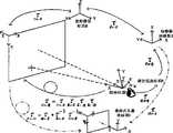
图3是具有视线跟踪功能的增强现实自然交互式头盔的工作原理图Figure 3 is a schematic diagram of the working principle of the augmented reality natural interactive helmet with gaze tracking function
具体实施方式Detailed ways
图1和图2所示的具有视线跟踪功能的增强现实自然交互式头盔,包括场景摄像机1、耳机和话筒2、电磁式位置跟踪器发射器3、瞳孔间距调节旋钮4、头盔垂直调节旋钮5、头盔水平调节旋钮6、头盔内衬7等组成。基本光路包括微型显示器9、红外高反滤光片10、半透半反组合光镜11、红外高透滤光片12、眼摄像机13、红外光源14,主要完成使用人员视线跟踪和虚拟物体显示功能。The augmented reality natural interactive helmet with gaze tracking function shown in Fig. 1 and Fig. 2 includes
在图1中,场景摄像机1完成自然场景采集,耳机和话筒2完成语音交互,电磁式位置跟踪器发射器3采用电磁式跟踪,内置于头盔上,完成头部位置跟踪。当不同的使用人员佩戴此头盔时,由于每个人的头部大小和瞳孔间距不同,可以通过头盔垂直调节旋钮5和头盔水平调节旋钮6调节头盔内衬7的大小,通过瞳孔间距调节旋钮4调节光路之间的距离,使虚拟图像显示效果最佳。In Figure 1,
头盔内部光路置于头盔光路盒内,由两套独立的光路设备组成,分别对应人的左右眼。光路设备之间的距离可由瞳孔间距调节旋钮4进行调节。图2为集成系统光路图,视线跟踪系统的光路为放置在眼睛斜上方的红外光源14发出的红外光照射到人眼,人眼反射的红外光穿过其前方的半透半反组合光镜11之后被红外高反片10反射改变方向平行传播,经红外高透片12进入红外眼摄像机13成像;光学透视式头盔光路为显示在微型显示器9上的虚拟信息发出的光线经透镜之后照射到半透半反组合光镜11上,从该组合器反射的光线被人眼接收,使人眼能够感知虚拟信息,加上场景光线,用户能够同时感知真实场景和虚拟信息,获得真实场景的增强效果。The internal optical path of the helmet is placed in the helmet optical path box, which is composed of two sets of independent optical path equipment, corresponding to the left and right eyes of the person respectively. The distance between the optical path devices can be adjusted by the interpupillary distance adjustment knob 4 . Fig. 2 is a diagram of the optical path of the integrated system. The optical path of the line of sight tracking system is that the infrared light emitted by the infrared light source 14 placed obliquely above the eyes illuminates the human eye, and the infrared light reflected by the human eye passes through the semi-transparent and semi-reflective combination mirror in front of it. After 11, it is reflected by the infrared high-reflection sheet 10 and changes direction to parallel propagation, and enters the infrared eye camera 13 for imaging through the infrared high-transmission sheet 12; On the semi-transparent and semi-reflective combination mirror 11, the light reflected from the combiner is received by the human eyes, so that the human eyes can perceive the virtual information, and with the scene light, the user can perceive the real scene and the virtual information at the same time, and obtain the enhancement of the real scene Effect.
以下结合图3叙述本发明的工作原理Describe working principle of the present invention below in conjunction with Fig. 3
基于视线跟踪的增强现实系统,首先需要实时跟踪用户注视点在真实场景中的位置;然后根据预先保存在数据库里的场景先验知识,由注视点在场景中的真实坐标结合场景摄像机获得的场景图像判断用户的感兴趣区域和具体目标,从而得到需要显示增强信息的被增强对象;最后,依据当前识别的目标信息去查询虚拟对象数据库,获得与真实场景匹配的虚拟增强信息,采用增强现实三维注册和虚实融合技术,对当前用户感兴趣区域目标进行信息增强。其中,视线跟踪部分用于跟踪用户的注视点,对应于

视线跟踪
注视点在眼坐标系E的坐标为Fe=(xe,ye,ze,1)T,在屏幕坐标系O下的坐标Fo=(xo,yo,zo,1)T,由图2描述的关系可知The coordinates of the gaze point in the eye coordinate system E are Fe = (xe , ye , ze , 1)T , and the coordinates in the screen coordinate system O are Fo = (xo , yo , zo , 1)T , we can know from the relationship described in Figure 2
其中:


采用欧拉角和平移向量描述


将式(2)展开可以消去xe改写为The expansion of formula (2) can eliminate xe and rewrite it as
gxy=F(P,MB←S) (3)gxy =F(P, MB←S ) (3)
其中:gxy为由注视点计算算法计算得到的二维屏幕坐标,P为12个模型参数集合,MB←S为位置跟踪器读数校准后的值,F是注视点计算函数。定义平均注视点误差Dmean为Among them: gxy is the two-dimensional screen coordinates calculated by the gaze point calculation algorithm, P is a set of 12 model parameters, MB←S is the value after calibration of the position tracker readings, and F is the gaze point calculation function. Define the average gaze point error Dmean as
其中:Gxy为标定过程中采集的实际注视点屏幕坐标,n为注视点的总个数,由(2)和(3)

由于眼当前坐标系E与眼主视坐标系R的坐标原点均为眼球旋转中心,因此

β=arg tan(|xc-xg|/D)β=arg tan(|xc -xg |/D)
注视点计算Foveation calculation
系统标定完成后,可通过公式(6)计算用户注视点在屏幕坐标系下的坐标(X,Y,0,1)TAfter the system calibration is completed, the coordinates (X, Y, 0, 1)T of the user's gaze point in the screen coordinate system can be calculated by formula (6)
式中r1、r4、r7、tx、ty、tz为
虚拟信息注册的计算Virtual information registration calculation
为了将虚拟增强信息准确放置在场景中,需要获得当前场景与光学透视式头盔显示器之间的变换关系,即求解世界坐标系与光学透视式头盔显示器的相对变换关系。In order to accurately place the virtual augmented information in the scene, it is necessary to obtain the transformation relationship between the current scene and the optical see-through head-mounted display, that is, to solve The relative transformation relationship between the world coordinate system and the optical see-through head-mounted display.
其中:


佩戴光学透视式头盔显示器,来自周围真实场景中的图像直接成像于用户视网膜上。光学透视式头盔显示器的标定采用SPAAM单点对准算法,把人眼和光学透视式头盔显示器看作一个虚拟摄像机,通过摄像机针孔模型来对它进行标定,基本步骤如下:Wearing an optical see-through head-mounted display, images from the surrounding real scene are directly imaged on the user's retina. The calibration of the optical see-through head-mounted display adopts the SPAAM single-point alignment algorithm. The human eye and the optical see-through head-mounted display are regarded as a virtual camera, and it is calibrated through the camera pinhole model. The basic steps are as follows:
①在显示器任意位置显示一真实标志点,并记录该点的世界坐标坐标(xw,yw,zw,1)T;①Display a real mark point at any position on the display, and record the world coordinates (xw , yw , zw , 1)T of the point;
②计算机生成n(n≥6)个虚拟标志点,按等间距排列显示在光学透视式头盔显示器上,记录该n个点的在头盔显示器坐标系下的坐标(xi,yi,1)T。用户移动头部,使得虚拟标志点与眼睛看到的屏幕上标志点完全重合,每对准一个标志点,记录一次位置跟踪器读数;②The computer generates n (n≥6) virtual marker points, which are arranged at equal intervals and displayed on the optical see-through head-mounted display, and record the coordinates (xi , yi , 1) of the n points in the coordinate system of the head-mounted displayT. The user moves the head so that the virtual marker point completely coincides with the marker point on the screen seen by the eyes, and records the reading of the position tracker every time a marker point is aligned;
③依据

④将(xi,yi,1)T和(XMi,YMi,ZMi,1)T代入公式(8)用SVD分解法求解
Claims (1)
Priority Applications (1)
| Application Number | Priority Date | Filing Date | Title |
|---|---|---|---|
| CNB2007100229788ACN100487568C (en) | 2007-05-29 | 2007-05-29 | Enhanced real natural interactive helmet with sight line follow-up function |
Applications Claiming Priority (1)
| Application Number | Priority Date | Filing Date | Title |
|---|---|---|---|
| CNB2007100229788ACN100487568C (en) | 2007-05-29 | 2007-05-29 | Enhanced real natural interactive helmet with sight line follow-up function |
Publications (2)
| Publication Number | Publication Date |
|---|---|
| CN101067716A CN101067716A (en) | 2007-11-07 |
| CN100487568Ctrue CN100487568C (en) | 2009-05-13 |
Family
ID=38880305
Family Applications (1)
| Application Number | Title | Priority Date | Filing Date |
|---|---|---|---|
| CNB2007100229788AExpired - Fee RelatedCN100487568C (en) | 2007-05-29 | 2007-05-29 | Enhanced real natural interactive helmet with sight line follow-up function |
Country Status (1)
| Country | Link |
|---|---|
| CN (1) | CN100487568C (en) |
Families Citing this family (44)
| Publication number | Priority date | Publication date | Assignee | Title |
|---|---|---|---|---|
| US9566029B2 (en) | 2008-09-30 | 2017-02-14 | Cognisens Inc. | Method and device for assessing, training and improving perceptual-cognitive abilities of individuals |
| DE102009049073A1 (en) | 2009-10-12 | 2011-04-21 | Metaio Gmbh | Method for presenting virtual information in a view of a real environment |
| KR101729023B1 (en)* | 2010-10-05 | 2017-04-21 | 엘지전자 주식회사 | Mobile terminal and operation control method thereof |
| FR2970576B1 (en)* | 2011-01-19 | 2013-02-08 | Matchic Labs | METHOD FOR DETERMINING THE DIRECTION OF THE LOOK AND DEVICE FOR IMPLEMENTING IT |
| JP6144681B2 (en)* | 2011-08-30 | 2017-06-07 | マイクロソフト テクノロジー ライセンシング,エルエルシー | Head mounted display with iris scan profiling function |
| CN102572217B (en)* | 2011-12-29 | 2014-08-20 | 华为技术有限公司 | Visual-attention-based multimedia processing method and device |
| CN103150013A (en)* | 2012-12-20 | 2013-06-12 | 天津三星光电子有限公司 | Mobile terminal |
| US10527859B2 (en)* | 2013-04-11 | 2020-01-07 | Sony Corporation | Image display device and display apparatus |
| US9524580B2 (en)* | 2014-01-06 | 2016-12-20 | Oculus Vr, Llc | Calibration of virtual reality systems |
| CN104089606B (en)* | 2014-06-30 | 2016-08-17 | 天津大学 | A kind of free space eye tracking measuring method |
| CN104317055B (en)* | 2014-10-31 | 2017-01-25 | 成都理想境界科技有限公司 | Head-mounted type device used in cooperation with mobile terminal |
| WO2016082062A1 (en)* | 2014-11-24 | 2016-06-02 | 潘有程 | 3d display helmet having wireless transmission function |
| CN104484523B (en)* | 2014-12-12 | 2017-12-08 | 西安交通大学 | A kind of augmented reality induction maintenance system realizes apparatus and method for |
| CN104581126A (en)* | 2014-12-16 | 2015-04-29 | 青岛歌尔声学科技有限公司 | Image display processing method and processing device for head-mounted display device |
| CN105828021A (en)* | 2015-01-05 | 2016-08-03 | 沈阳新松机器人自动化股份有限公司 | Specialized robot image acquisition control method and system based on augmented reality technology |
| WO2016115870A1 (en)* | 2015-01-21 | 2016-07-28 | 成都理想境界科技有限公司 | Binocular ar head-mounted display device and information displaying method therefor |
| CN104570356A (en)* | 2015-02-03 | 2015-04-29 | 深圳市安华光电技术有限公司 | Single image source binocular near-to-eye display device |
| CN112764536B (en)* | 2015-03-05 | 2025-04-01 | 奇跃公司 | Systems and methods for augmented reality |
| CN104731338B (en)* | 2015-03-31 | 2017-11-14 | 深圳市虚拟现实科技有限公司 | One kind is based on enclosed enhancing virtual reality system and method |
| CN104865705A (en)* | 2015-05-04 | 2015-08-26 | 上海交通大学 | Reinforced realistic headwear equipment based intelligent mobile equipment |
| CN105068252A (en)* | 2015-09-07 | 2015-11-18 | 东南大学 | Multi-parameter adjustable binocular augmented reality experimental device |
| CN105686835A (en)* | 2016-01-18 | 2016-06-22 | 张江杰 | Eyesight visualization device |
| FR3049722B1 (en) | 2016-04-01 | 2018-03-30 | Thales | VISUALIZATION SYSTEM FOR A PONTET HEAD FOR AN AIRCRAFT COMPATIBLE WITH AN AUDIO HELMET |
| CN105955456B (en)* | 2016-04-15 | 2018-09-04 | 深圳超多维科技有限公司 | The method, apparatus and intelligent wearable device that virtual reality is merged with augmented reality |
| CN106127858B (en)* | 2016-06-24 | 2020-06-23 | 联想(北京)有限公司 | Information processing method and electronic equipment |
| CN107765842A (en)* | 2016-08-23 | 2018-03-06 | 深圳市掌网科技股份有限公司 | A kind of augmented reality method and system |
| CN108572450B (en)* | 2017-03-09 | 2021-01-29 | 宏碁股份有限公司 | Head-mounted display, visual field correction method thereof and mixed reality display system |
| CN106959516A (en)* | 2017-05-02 | 2017-07-18 | 广州蜃境信息科技有限公司 | One kind is based on shuangping san augmented reality glasses |
| CN107657235A (en)* | 2017-09-28 | 2018-02-02 | 北京小米移动软件有限公司 | Recognition methods and device based on augmented reality |
| CN108196676B (en)* | 2018-01-02 | 2021-04-13 | 联想(北京)有限公司 | Tracking identification method and system |
| TWI702548B (en)* | 2018-04-23 | 2020-08-21 | 財團法人工業技術研究院 | Controlling system and controlling method for virtual display |
| CN108765498B (en)* | 2018-05-30 | 2019-08-23 | 百度在线网络技术(北京)有限公司 | Monocular vision tracking, device and storage medium |
| WO2020023524A1 (en)* | 2018-07-23 | 2020-01-30 | Magic Leap, Inc. | Method and system for resolving hemisphere ambiguity using a position vector |
| JP2020053874A (en)* | 2018-09-27 | 2020-04-02 | セイコーエプソン株式会社 | Head-mounted display device and cover member |
| CN109615664B (en)* | 2018-12-12 | 2020-06-30 | 亮风台(上海)信息科技有限公司 | Calibration method and device for optical perspective augmented reality display |
| CN110333775A (en)* | 2019-05-16 | 2019-10-15 | 上海精密计量测试研究所 | An augmented reality maintenance guidance system and method for aerospace equipment |
| CN110147770A (en)* | 2019-05-23 | 2019-08-20 | 北京七鑫易维信息技术有限公司 | A kind of gaze data restoring method and system |
| CN110572632A (en)* | 2019-08-15 | 2019-12-13 | 中国人民解放军军事科学院国防科技创新研究院 | Augmented reality display system, helmet and method based on sight tracking |
| CN111044258B (en)* | 2019-11-28 | 2021-09-28 | 扬州莱达光电技术有限公司 | Simulation testing device in helmet of helmet display |
| CN113110732B (en)* | 2020-01-13 | 2024-12-27 | 苏州佳世达电通有限公司 | Eye tracking control method and system for multi-screen display screen |
| CN114356482B (en)* | 2021-12-30 | 2023-12-12 | 业成科技(成都)有限公司 | Method for interaction with human-computer interface by using line-of-sight drop point |
| CN114494594B (en)* | 2022-01-18 | 2023-11-28 | 中国人民解放军63919部队 | Deep learning-based astronaut operation equipment state identification method |
| CN115284076A (en)* | 2022-07-21 | 2022-11-04 | 太原重工股份有限公司 | Alignment method of workpiece positioning datum |
| CN118091946A (en)* | 2024-03-09 | 2024-05-28 | 山东泰视智能技术有限公司 | Universal smart glasses with detection and protection functions |
Citations (7)
| Publication number | Priority date | Publication date | Assignee | Title |
|---|---|---|---|---|
| US5347400A (en)* | 1993-05-06 | 1994-09-13 | Ken Hunter | Optical system for virtual reality helmet |
| US5572749A (en)* | 1994-06-28 | 1996-11-12 | The Walt Disney Company | Helmet mounting device and system |
| CN1161087A (en)* | 1994-08-10 | 1997-10-01 | 实质(Ip)有限公司 | Head mounted display optics |
| US6120461A (en)* | 1999-08-09 | 2000-09-19 | The United States Of America As Represented By The Secretary Of The Army | Apparatus for tracking the human eye with a retinal scanning display, and method thereof |
| CN1584791A (en)* | 2004-06-11 | 2005-02-23 | 上海大学 | Man-machine interactive method and apparatus |
| CN1648840A (en)* | 2005-01-27 | 2005-08-03 | 北京理工大学 | A head-mounted stereo vision gesture recognition device |
| CN101077232A (en)* | 2007-06-07 | 2007-11-28 | 南京航空航天大学 | Human-computer interaction helmet for type computer |
- 2007
- 2007-05-29CNCNB2007100229788Apatent/CN100487568C/ennot_activeExpired - Fee Related
Patent Citations (7)
| Publication number | Priority date | Publication date | Assignee | Title |
|---|---|---|---|---|
| US5347400A (en)* | 1993-05-06 | 1994-09-13 | Ken Hunter | Optical system for virtual reality helmet |
| US5572749A (en)* | 1994-06-28 | 1996-11-12 | The Walt Disney Company | Helmet mounting device and system |
| CN1161087A (en)* | 1994-08-10 | 1997-10-01 | 实质(Ip)有限公司 | Head mounted display optics |
| US6120461A (en)* | 1999-08-09 | 2000-09-19 | The United States Of America As Represented By The Secretary Of The Army | Apparatus for tracking the human eye with a retinal scanning display, and method thereof |
| CN1584791A (en)* | 2004-06-11 | 2005-02-23 | 上海大学 | Man-machine interactive method and apparatus |
| CN1648840A (en)* | 2005-01-27 | 2005-08-03 | 北京理工大学 | A head-mounted stereo vision gesture recognition device |
| CN101077232A (en)* | 2007-06-07 | 2007-11-28 | 南京航空航天大学 | Human-computer interaction helmet for type computer |
Also Published As
| Publication number | Publication date |
|---|---|
| CN101067716A (en) | 2007-11-07 |
Similar Documents
| Publication | Publication Date | Title |
|---|---|---|
| CN100487568C (en) | Enhanced real natural interactive helmet with sight line follow-up function | |
| US11640064B2 (en) | Wearable pupil-forming display apparatus | |
| US11628038B2 (en) | Multi-option all-digital 3D surgery visualization system and control | |
| US12062430B2 (en) | Surgery visualization theatre | |
| US11854171B2 (en) | Compensation for deformation in head mounted display systems | |
| US9984507B2 (en) | Eye tracking for mitigating vergence and accommodation conflicts | |
| CN204595327U (en) | Head-mounted display apparatus | |
| US20190121132A1 (en) | Binocular wide field of view (wfov) wearable optical display system | |
| JP6369005B2 (en) | Head-mounted display device and method for controlling head-mounted display device | |
| US20240266033A1 (en) | Surgery visualization theatre | |
| CN104298499A (en) | Information processing apparatus, information processing method, and information processing system | |
| KR20160033721A (en) | Information processing apparatus, information processing method, and information processing system | |
| JP2015508182A (en) | Compact line-of-sight head-mounted display | |
| JP2015019679A (en) | Information processing device, information processing method, and information processing system | |
| CN110879469A (en) | A head-mounted display device | |
| CN106840112A (en) | A kind of space geometry measuring method of utilization free space eye gaze point measurement | |
| CN107991775A (en) | It can carry out the wear-type visual device and human eye method for tracing of people's ocular pursuit | |
| WO2021226134A1 (en) | Surgery visualization theatre | |
| WO2016101861A1 (en) | Head-worn display device | |
| Sun et al. | A novel integrated eye-tracking system with stereo stimuli for 3-D gaze estimation | |
| CN113138664A (en) | Eyeball tracking system and method based on light field perception | |
| EP4106664A1 (en) | All-digital multi-option 3d surgery visualization system and control | |
| WO2022205769A1 (en) | Virtual reality system foveated rendering method and system based on single eyeball tracking | |
| CN107111143B (en) | Vision system and film viewer | |
| US20200159027A1 (en) | Head-mounted display with unobstructed peripheral viewing |
Legal Events
| Date | Code | Title | Description |
|---|---|---|---|
| C06 | Publication | ||
| PB01 | Publication | ||
| C10 | Entry into substantive examination | ||
| SE01 | Entry into force of request for substantive examination | ||
| C14 | Grant of patent or utility model | ||
| GR01 | Patent grant | ||
| CF01 | Termination of patent right due to non-payment of annual fee | Granted publication date:20090513 Termination date:20160529 |