CN100484601C - Z-filter media pack arrangements and methods - Google Patents
Z-filter media pack arrangements and methodsDownload PDFInfo
- Publication number
- CN100484601C CN100484601CCNB2005800258243ACN200580025824ACN100484601CCN 100484601 CCN100484601 CCN 100484601CCN B2005800258243 ACNB2005800258243 ACN B2005800258243ACN 200580025824 ACN200580025824 ACN 200580025824ACN 100484601 CCN100484601 CCN 100484601C
- Authority
- CN
- China
- Prior art keywords
- media
- seal
- filter
- media pack
- corrugated
- Prior art date
- Legal status (The legal status is an assumption and is not a legal conclusion. Google has not performed a legal analysis and makes no representation as to the accuracy of the status listed.)
- Expired - Lifetime
Links
Images


Classifications
- B—PERFORMING OPERATIONS; TRANSPORTING
- B01—PHYSICAL OR CHEMICAL PROCESSES OR APPARATUS IN GENERAL
- B01D—SEPARATION
- B01D46/00—Filters or filtering processes specially modified for separating dispersed particles from gases or vapours
- B01D46/52—Particle separators, e.g. dust precipitators, using filters embodying folded corrugated or wound sheet material
- B01D46/521—Particle separators, e.g. dust precipitators, using filters embodying folded corrugated or wound sheet material using folded, pleated material
- B01D46/525—Particle separators, e.g. dust precipitators, using filters embodying folded corrugated or wound sheet material using folded, pleated material which comprises flutes
- B01D46/527—Particle separators, e.g. dust precipitators, using filters embodying folded corrugated or wound sheet material using folded, pleated material which comprises flutes in wound arrangement
- B—PERFORMING OPERATIONS; TRANSPORTING
- B01—PHYSICAL OR CHEMICAL PROCESSES OR APPARATUS IN GENERAL
- B01D—SEPARATION
- B01D25/00—Filters formed by clamping together several filtering elements or parts of such elements
- B01D25/001—Making filtering elements not provided for elsewhere
- B—PERFORMING OPERATIONS; TRANSPORTING
- B01—PHYSICAL OR CHEMICAL PROCESSES OR APPARATUS IN GENERAL
- B01D—SEPARATION
- B01D25/00—Filters formed by clamping together several filtering elements or parts of such elements
- B01D25/22—Cell-type filters
- B01D25/24—Cell-type roll filters
- B—PERFORMING OPERATIONS; TRANSPORTING
- B01—PHYSICAL OR CHEMICAL PROCESSES OR APPARATUS IN GENERAL
- B01D—SEPARATION
- B01D46/00—Filters or filtering processes specially modified for separating dispersed particles from gases or vapours
- B01D46/0001—Making filtering elements
- B—PERFORMING OPERATIONS; TRANSPORTING
- B01—PHYSICAL OR CHEMICAL PROCESSES OR APPARATUS IN GENERAL
- B01D—SEPARATION
- B01D46/00—Filters or filtering processes specially modified for separating dispersed particles from gases or vapours
- B01D46/52—Particle separators, e.g. dust precipitators, using filters embodying folded corrugated or wound sheet material
- B01D46/521—Particle separators, e.g. dust precipitators, using filters embodying folded corrugated or wound sheet material using folded, pleated material
- B01D46/525—Particle separators, e.g. dust precipitators, using filters embodying folded corrugated or wound sheet material using folded, pleated material which comprises flutes
- B—PERFORMING OPERATIONS; TRANSPORTING
- B29—WORKING OF PLASTICS; WORKING OF SUBSTANCES IN A PLASTIC STATE IN GENERAL
- B29D—PRODUCING PARTICULAR ARTICLES FROM PLASTICS OR FROM SUBSTANCES IN A PLASTIC STATE
- B29D99/00—Subject matter not provided for in other groups of this subclass
- B—PERFORMING OPERATIONS; TRANSPORTING
- B01—PHYSICAL OR CHEMICAL PROCESSES OR APPARATUS IN GENERAL
- B01D—SEPARATION
- B01D2201/00—Details relating to filtering apparatus
- B01D2201/34—Seals or gaskets for filtering elements
- B—PERFORMING OPERATIONS; TRANSPORTING
- B01—PHYSICAL OR CHEMICAL PROCESSES OR APPARATUS IN GENERAL
- B01D—SEPARATION
- B01D2265/00—Casings, housings or mounting for filters specially adapted for separating dispersed particles from gases or vapours
- B01D2265/04—Permanent measures for connecting different parts of the filter, e.g. welding, glueing or moulding
- B—PERFORMING OPERATIONS; TRANSPORTING
- B01—PHYSICAL OR CHEMICAL PROCESSES OR APPARATUS IN GENERAL
- B01D—SEPARATION
- B01D2271/00—Sealings for filters specially adapted for separating dispersed particles from gases or vapours
- B01D2271/02—Gaskets, sealings
- Y—GENERAL TAGGING OF NEW TECHNOLOGICAL DEVELOPMENTS; GENERAL TAGGING OF CROSS-SECTIONAL TECHNOLOGIES SPANNING OVER SEVERAL SECTIONS OF THE IPC; TECHNICAL SUBJECTS COVERED BY FORMER USPC CROSS-REFERENCE ART COLLECTIONS [XRACs] AND DIGESTS
- Y02—TECHNOLOGIES OR APPLICATIONS FOR MITIGATION OR ADAPTATION AGAINST CLIMATE CHANGE
- Y02E—REDUCTION OF GREENHOUSE GAS [GHG] EMISSIONS, RELATED TO ENERGY GENERATION, TRANSMISSION OR DISTRIBUTION
- Y02E50/00—Technologies for the production of fuel of non-fossil origin
- Y02E50/10—Biofuels, e.g. bio-diesel
- Y—GENERAL TAGGING OF NEW TECHNOLOGICAL DEVELOPMENTS; GENERAL TAGGING OF CROSS-SECTIONAL TECHNOLOGIES SPANNING OVER SEVERAL SECTIONS OF THE IPC; TECHNICAL SUBJECTS COVERED BY FORMER USPC CROSS-REFERENCE ART COLLECTIONS [XRACs] AND DIGESTS
- Y02—TECHNOLOGIES OR APPLICATIONS FOR MITIGATION OR ADAPTATION AGAINST CLIMATE CHANGE
- Y02E—REDUCTION OF GREENHOUSE GAS [GHG] EMISSIONS, RELATED TO ENERGY GENERATION, TRANSMISSION OR DISTRIBUTION
- Y02E50/00—Technologies for the production of fuel of non-fossil origin
- Y02E50/30—Fuel from waste, e.g. synthetic alcohol or diesel
Landscapes
- Chemical & Material Sciences (AREA)
- Chemical Kinetics & Catalysis (AREA)
- Engineering & Computer Science (AREA)
- Mechanical Engineering (AREA)
- Filtering Of Dispersed Particles In Gases (AREA)
- Filtering Materials (AREA)
- Separation Using Semi-Permeable Membranes (AREA)
- Packaging For Recording Disks (AREA)
- Liquid Crystal Substances (AREA)
Abstract
Description
Translated fromChinese对相关申请的交叉引用Cross References to Related Applications
[0001]根据35 U.S.C.§119(e),本申请要求申请日为2004年6月8日的临时专利申请流水号60/578,482的优先权。申请60/578,482的完整内容在此被结合入本文。[0001] According to 35 U.S.C. § 119 (e), this application claims the priority of provisional patent application serial number 60/578,482 filed June 8, 2004. The entire contents of application 60/578,482 are hereby incorporated herein.
技术领域technical field
[0002]本发明涉及用于过滤液体或气体的过滤介质。本发明尤其涉及使用z-过滤介质的介质包,它包括波纹状介质片材固定在表面片材上,形成介质包。具体地讲,本发明涉及形成所述的介质包,以及将它们用于可维修的过滤器滤芯结构中,通常用于空气滤清器中。还披露了组装和使用方法。[0002] The present invention relates to filter media for filtering liquids or gases. More particularly, the present invention relates to media packs utilizing z-filter media comprising a sheet of corrugated media secured to a facing sheet to form the media pack. In particular, the invention relates to the formation of such media packs and their use in serviceable filter cartridge constructions, typically in air cleaners. Methods of assembly and use are also disclosed.
背景技术Background technique
[0003]流体流,例如空气和液体,其内可能携带杂质材料。在很多情况下,需要从流体流过滤某些或全部杂质材料。例如,进入机动车辆或发电设备的发动机的空气流(例如,助燃空气),进入燃气轮机系统的气流和进入各种燃炉的空气流,其内携带有应该过滤的颗粒状杂质。另外,液体流和发动机润滑系统,液压系统,冷却系统和燃油系统,携带有应当过滤的杂质。对于这些系统,优选将选定的杂质材料从所述流体中除去(或使其含量降低)。业已开发出了用于排出杂质的多种流体过滤器(空气或液体过滤器)结构。不过,需要持续地改进。[0003] Fluid streams, such as air and liquids, may carry foreign materials therein. In many instances, it is desirable to filter some or all of the foreign material from a fluid stream. For example, air streams (eg, combustion air) entering engines of motor vehicles or power generating equipment, air streams entering gas turbine systems, and air streams entering various furnaces carry particulate impurities that should be filtered. In addition, the fluid flow and engine lubrication system, hydraulic system, cooling system and fuel system, carry impurities that should be filtered. For these systems, it is preferred that selected impurity materials be removed (or reduced in level) from the fluid. Various fluid filter (air or liquid filter) configurations have been developed for the removal of impurities. However, continuous improvement is required.
发明内容Contents of the invention
[0004]根据本发明,提供了可用于优选的过滤器滤芯,例如空气过滤器滤芯的特征。所述特征可以一起使用,以提供优选的过滤器滤芯,不过某些优选的滤芯可被构造成只使用选定的一些特征。另外,提供了构造和使用方法。[0004] In accordance with the present invention, features are provided that may be used in a preferred filter cartridge, such as an air filter cartridge. The features described may be used together to provide preferred filter cartridges, although some preferred cartridges may be configured to use only selected features. In addition, construction and usage methods are provided.
[0005]根据本发明,通常的优选过滤器滤芯包括卷绕的介质组合和在位固化的护套。所述卷绕的介质组合优选包括槽纹片材固定至表面片材的卷绕结构,最优选使表面片材向外。所述卷绕介质一般形成了在卷绕介质组合的第一和第二相对流动端之间延伸的外侧壁。[0005] According to the present invention, a generally preferred filter cartridge comprises a coiled media pack and a cured-in-place jacket. The coiled media combination preferably comprises a coiled configuration with a fluted sheet secured to a facing sheet, most preferably with the facing sheet outward. The coiled media generally forms an outer sidewall extending between first and second opposing flow ends of the coiled media combination.
[0006]所述在位固化的护套优选完全环绕并且覆盖所述外侧壁,覆盖第一和第二流动端之间外侧壁延伸部分长度的至少80%,更优选是所述长度的至少95%,最优选完全覆盖所述长度。所述在位固化的护套优选被设置成密封介质组合的外端或尾端。[0006] The cured-in-place jacket preferably completely surrounds and covers the outer sidewall, covering at least 80% of the length of the extension of the outer sidewall between the first and second flow ends, more preferably at least 95% of said length %, most preferably completely covering the length. The cured-in-place sheath is preferably configured to seal the outer or trailing end of the media pack.
[0007]在一些情况,所述过滤器滤芯包括在位模制的中心件或核心。在一些情况下,在使用时,所述在位模制的中心件或核心包括凹入端,每个凹入端各自形成密封区域,用于密封卷绕介质组合的部分内端或前端。[0007] In some cases, the filter cartridge includes a molded-in-place centerpiece or core. In some cases, when in use, the molded-in-place centerpiece or core includes recessed ends each forming a respective sealing region for sealing a portion of the inner or leading end of the coiled media assembly.
[0008]一种示例的空气过滤器滤芯同时使用在位固化的护套和在位模制的中心件或核心。[0008] An exemplary air filter cartridge uses both a cured-in-place jacket and a mold-in-place centerpiece or core.
[0009]所述在位固化的护套优选包括在位模制的包胶模(overmold),它包括与之成一体的外壳密封结构。通常的外壳密封结构是轴向收聚密封。[0009] The cured-in-place jacket preferably comprises a molded-in-place overmold including an integral housing seal structure. The usual housing seal structure is an axial pinch seal.
[0010]通常,聚氨酯是包胶模、外壳密封件和在位模制的中心件的优选材料。最优选的,它是泡沫聚氨酯。[0010] In general, polyurethane is the material of choice for overmolds, housing seals, and molded-in-place centerpieces. Most preferably, it is foamed polyurethane.
[0011]提供了用于制备优选组件的模制结构和技术。[0011] Molding structures and techniques for making preferred assemblies are provided.
附图说明Description of drawings
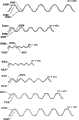
[0012]图1是可用于本发明结构中z-过滤介质的局部,示意性透视图。[0012] FIG. 1 is a partial, schematic perspective view of a z-filter media that may be used in the construction of the present invention.
[0013]图2是图1所示介质的一部分的示意性剖视图。[0013] FIG. 2 is a schematic cross-sectional view of a portion of the media shown in FIG. 1.
[0014]图3是各种波纹状介质定义的示例的示意图。[0014] FIG. 3 is a schematic diagram of examples of various corrugated media definitions.
[0015]图4是根据本发明制造介质的工艺的示意图。[0015] FIG. 4 is a schematic diagram of a process for fabricating a media according to the present invention.
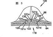
[0016]图5是根据本发明可用于结构中介质槽纹的可选末端针刺的剖视图。[0016] FIG. 5 is a cross-sectional view of an optional end needling that may be used for media flutes in a structure in accordance with the present invention.
[0017]图6是根据本发明的过滤器滤芯的侧视图。[0017] FIG. 6 is a side view of a filter cartridge according to the present invention.
[0018]图7是图6所示元件的剖视图。[0018] FIG. 7 is a cross-sectional view of the element shown in FIG. 6.
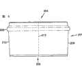
[0019]图8是其内具有介质包的模制结构的示意图,用于形成图6的过滤器滤芯。[0019] FIG. 8 is a schematic illustration of a molded structure with a media pack therein for forming the filter cartridge of FIG. 6.
[0020]图9是图8所示模制结构的第一部分的放大局部示意图。[0020] FIG. 9 is an enlarged fragmentary schematic view of a first portion of the molded structure shown in FIG. 8.
[0021]图10是图8所示模制结构的第二部分的放大局部示意图。[0021] FIG. 10 is an enlarged partial schematic view of a second portion of the molded structure shown in FIG.
[0022]图11是根据本发明的第二种过滤器滤芯的示意性侧视图。[0022] FIG. 11 is a schematic side view of a second filter cartridge according to the present invention.
[0023]图12是图11所示过滤器滤芯的透视图。[0023] FIG. 12 is a perspective view of the filter cartridge shown in FIG. 11.
[0024]图13是根据本发明形成另一种过滤器滤芯的工艺的示意图。[0024] FIG. 13 is a schematic illustration of a process for forming another filter cartridge in accordance with the present invention.
[0025]图14是根据本发明制成另一种过滤器滤芯的第二种工艺的示意图。[0025] FIG. 14 is a schematic diagram of a second process for making another filter element according to the present invention.
[0026]图15是具有本发明特征的长圆形过滤器滤芯的透视图。[0026] FIG. 15 is a perspective view of an oblong filter cartridge having features of the present invention.
[0027]图16是沿图15中线16-16的剖视图。[0027] FIG. 16 is a cross-sectional view along line 16-16 of FIG. 15.
[0028]图17是第二种长圆形滤芯的剖视图。[0028] Figure 17 is a cross-sectional view of the second oblong filter element.
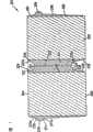
[0029]图18是其内具有介质包的模制结构的示意性剖视图,用于形成图17的结构。[0029] FIG. 18 is a schematic cross-sectional view of a molded structure with a media pack therein for forming the structure of FIG. 17.
[0030]图19是图18所示模制结构的剖视图,沿图18中箭头19-19的方向剖开。[0030] FIG. 19 is a cross-sectional view of the molded structure shown in FIG. 18, taken in the direction of arrows 19-19 in FIG. 18.
具体实施方式Detailed ways
I. Z-过滤介质结构,概述I. Z-filter media structure, overview
[0031]可用槽纹过滤介质以多种方式提供流体过滤器结构。一种众所周知的方式是z-过滤器结构。在本文中,术语"z-过滤器结构"用于表示这样的过滤器结构,其中,单个槽纹状、折叠或以其他方式形成的过滤器槽纹被用于形成多组纵向的,通常平行的入口和出口过滤器槽纹,用于流体流过所述介质;所述流体沿所述介质相对的入口和出口流动端(或流动面)之间的槽纹长度流动。z-过滤介质的某些示例可以参见美国专利5,820,646;5,772,883;5,902,364;5,792,247;5,895,574;6,210,469;6,190,432;6,350,296;6,179,890;6,235,195;Des.399,944;Des.428,128;Des.396,098;Des.398,046;和Des.437,401;上述15件引用文献的每一件在此被结合入本文。[0031] Fluted filter media can be used to provide fluid filter construction in a variety of ways. One well known way is the z-filter structure. As used herein, the term "z-filter structure" is used to denote a filter structure in which a single fluted, folded, or otherwise formed filter flute is used to form multiple sets of longitudinal, usually parallel inlet and outlet filter flutes for fluid flow through the media; the fluid flows along the length of the flutes between opposing inlet and outlet flow ends (or flow faces) of the media. z-过滤介质的某些示例可以参见美国专利5,820,646;5,772,883;5,902,364;5,792,247;5,895,574;6,210,469;6,190,432;6,350,296;6,179,890;6,235,195;Des.399,944;Des.428,128;Des.396,098;Des.398,046;和Des .437,401; each of the above 15 citations is hereby incorporated herein.
[0032]一种类型的z-过滤介质,使用两种特定的介质部件结合在一起,以形成介质结构。所述两种部件是:(1)槽纹状(通常是波纹状)介质片材;和,(2)表面介质片材。所述表面介质片材通常是非波纹状的,不过它可以是波纹状的,例如垂直于槽纹方向,如申请日为2004年2月11日的美国临时申请60/543,804所描述的,该文献在此被结合入本文。在本文中,所述表面片材有时候被表征为扁平的,如果它是非波纹状和非槽纹状的,即使它在过滤介质结构中被卷绕。[0032] One type of z-filter media uses two specific media components bonded together to form the media structure. The two components are: (1) a fluted (usually corrugated) media sheet; and, (2) a facing media sheet. The facing media sheet is typically non-corrugated, although it may be corrugated, for example perpendicular to the direction of the flutes, as described in U.S. Provisional Application 60/543,804, filed February 11, 2004, which is hereby incorporated herein. Herein, the facing sheet is sometimes characterized as flat if it is non-corrugated and non-fluted, even if it is coiled in a filter media structure.
[0033]所述槽纹状(通常是波纹状)介质片材和表面介质片材一起,被用于形成具有平行的入口和出口槽纹的介质。在某些情况下,所述槽纹片材和非槽纹片材固定在一起,然后卷绕形成z-过滤介质结构。所述结构描述在,例如,U.S.6,235,195和6,179,890中,所述每份文献在此被结合入本文。在某些其他结构中,波纹状介质的某些非卷绕部分固定在扁平介质上,彼此层叠,以形成过滤器结构。这种结构的一个示例参见5,820,646号专利的图11,该文献在此被结合入本文。[0033] The fluted (usually corrugated) media sheet, together with the facing media sheet, is used to form media with parallel inlet and outlet flutes. In some cases, the fluted and non-fluted sheets are secured together and then wound to form a z-filter media structure. Such structures are described, for example, in U.S. 6,235,195 and 6,179,890, each of which is hereby incorporated herein. In certain other constructions, certain uncoiled portions of corrugated media are secured to flat media and layered on top of each other to form filter constructions. An example of such a structure is shown in Figure 11 of Patent No. 5,820,646, which is hereby incorporated herein.
[0034]对于本文所述的具体应用,优选卷绕结构。[0034] For the particular application described herein, a wound configuration is preferred.
[0035]通常,使槽纹片材/表面片材组合自身卷绕,以形成卷绕的介质包,是使表面片材向外进行的。一些卷绕技术披露在申请日为2003年5月2日的美国临时申请60/467,521,和申请日为2004年3月17日的PCT申请US 04/07927中,所述每份文献在此被结合入本文。所得到的卷绕结构一般具有部分表面片材结果作为所述介质包的外表面。[0035] Typically, the fluted sheet/facing sheet combination is coiled on itself to form a coiled media pack, with the facing sheet outward. Some winding techniques are disclosed in U.S. provisional application 60/467,521, filed May 2, 2003, and PCT application US 04/07927, filed March 17, 2004, each of which is hereby incorporated by reference. incorporated into this article. The resulting rolled structure generally has a partial face sheet result as the outer surface of the media pack.
[0036]在本文中,术语"波纹状"是指介质结构,表示使介质在两个波纹辊之间通过,即,进入两个辊之间的辊隙或咬合部分所得到的槽纹结构,其中每个辊具有适合在所得到的介质上造成波纹效应的表面特征。术语"波纹"不是指由不涉及使介质通过波纹辊之间的咬合部分的技术所形成的槽纹。不过,术语"波纹状"适用在形成波纹之后即使介质被进一步改变或变形,例如通过披露于公开日为2004年1月22日的PCTWO 04/007054的折叠技术,该文献在此被结合入本文。[0036] As used herein, the term "corrugated" refers to a media structure, meaning the fluted structure obtained by passing the media between two corrugating rolls, i.e., into the nip or nip between the two rolls, Each of these rollers has surface features suitable for causing a dimple effect on the resulting media. The term "corrugation" does not refer to flutes formed by techniques that do not involve passing the media through a nip between corrugation rollers. However, the term "corrugated" applies even if the media is further altered or deformed after corrugation is formed, such as by the folding technique disclosed in PCTWO 04/007054, published January 22, 2004, which is hereby incorporated herein .
[0037]波纹状介质是特定形式的槽纹介质。槽纹介质是具有单独槽纹(例如通过压制波纹或折叠形成)延伸通过其间的介质。[0037] Corrugated media is a specific form of fluted media. Fluted media is media that has individual flutes (eg, formed by pressing corrugations or folding) extending therethrough.
[0038]采用z-过滤介质的可维修过滤元件或过滤器滤芯结构有时被称作"直通流动结构"或其变化形式。一般,在本文中,是指可维修过滤元件一般具有入口流动端(或面)和相对的出口流动端(或面),流体大体沿相同的直通方向进入和离开所述过滤器滤芯。在本文中,术语"可维修的"是指包含介质的过滤器滤芯定期从相应的流体滤清器中取出并更换。在一些情况下,每个入口流动端和出口流动端大体是扁平或平面的,两者彼此平行。不过,它的变化形式,例如非平面的表面是可行的。下面将描述非平面的相对流动面的示例。[0038] Serviceable filter element or filter cartridge configurations employing z-filter media are sometimes referred to as "straight-through flow configurations" or variations thereof. In general, as used herein, it is meant that a serviceable filter element generally has an inlet flow end (or face) and an opposite outlet flow end (or face) with fluid generally entering and exiting the filter cartridge in the same through-through direction. As used herein, the term "serviceable" means that the filter cartridge containing the media is periodically removed from the corresponding fluid filter and replaced. In some cases, each of the inlet and outlet flow ends is generally flat or planar, parallel to one another. However, variations thereof, such as non-planar surfaces, are possible. Examples of non-planar opposing flow surfaces are described below.
[0039]直通流动结构(特别对于卷绕的介质包)是,例如,与可维修的过滤器滤芯,诸如美国专利号6,039,778所示出的圆柱状折叠过滤器滤芯类型相反的,该文献在此被结合入本文,其中流体在通过可维修的滤芯时一般会转弯。就是说,在6,039,778的过滤器中,流体通过圆柱状侧面进入圆柱状过滤器滤芯,然后转向通过端面离开(在顺流系统)。在通常的逆流系统中,流体通过端面进入可维修的圆柱状滤芯,然后转向通过圆柱状过滤器滤芯的侧面离开。这种逆流系统的一个示例在美国专利号5,613,992中示出,该文献在此被结合入本文。[0039] Straight-through flow configurations (particularly for coiled media packs) are, for example, in contrast to serviceable filter cartridges, such as the cylindrical pleated filter cartridge type shown in U.S. Patent No. 6,039,778, which is hereby Incorporated herein, where fluid generally turns when passing through a serviceable element. That is, in the filter of 6,039,778, fluid enters the cylindrical filter element through the cylindrical sides and then turns to exit through the end faces (in a co-flow system). In a typical counterflow system, fluid enters the serviceable cylindrical element through the end face and turns to exit through the side of the cylindrical filter element. An example of such a countercurrent system is shown in US Patent No. 5,613,992, which is hereby incorporated herein.
[0040]在本文中使用的术语"z-过滤介质结构"及其变化形式,是指下述任意一种或全部:波纹状或其他槽纹状介质网固定在(表面)介质上,具有适当密封,以允许形成入口和出口槽纹;或,所述介质卷绕或以其他方式构造或形成三维入口和出口槽纹网络;和/或,包括所述介质的过滤器结构。[0040] The term "z-filter media construction" and variations thereof, as used herein, refers to any or all of the following: a web of corrugated or otherwise fluted media secured to (surface) media with appropriate seals to allow formation of inlet and outlet flutes; or, the media is coiled or otherwise configured or formed into a three-dimensional network of inlet and outlet flutes; and/or a filter structure comprising the media.
[0041]在图1中,示出了可用于z-过滤介质的介质1的示例。介质1由波纹片材3和表面片材4制成。[0041] In FIG. 1, an example of a
[0042]一般,图1中波纹片材3的类型一般在本文被表征为具有规则的,弯曲波型的槽纹或波纹7。在本文中,术语"波型"是指交替波谷7b和波峰7a的槽纹或波纹型式。在本文中,术语"规则的"是指这样的事实,即成对的波谷和波峰(7b,7a)以大体相同重复的波纹(或槽纹)形状和大小交替。(另外,通常在规则的结构中,每个波谷7b大致是每个波峰7a的倒置。)因此,术语"规则的"用于表示包括波谷和波峰的波纹(或槽纹)型式,每对(包括相邻的波谷和波峰)重复,在沿槽纹长度的至少70%上波纹的大小和形状没有显著的变化。在本文中,术语"大致"是指由于用于产生波纹或槽纹片材的工艺或形式的变化而导致的改变,而不是由于介质片材3是柔性的事实而产生的微小变化。对于重复型式的表征,并不意味着在任意给定的过滤器结构中,必须存在相同数量的波峰和波谷。介质1可以在,例如,一对波峰和波谷之间,或者部分沿一对波峰和波谷终止。(例如,在图1中,以局部形式示出的介质1具有八个完整的波峰7a和七个完整的波谷7b)。另外,相对的槽纹末端(波谷和波峰末端)可以彼此不同。末端的这些变化在上述定义中不予考虑,除非有专门说明。就是说,槽纹末端的变化倾向于包含在上述定义中。[0042] In general, the type of corrugated sheet 3 in Figure 1 is generally characterized herein as having flutes or corrugations 7 of a regular, curved wave pattern. In this context, the term "wave pattern" refers to a flute or corrugation pattern of alternating
[0043]在本文表征波纹的"弯曲的"波型时,术语"弯曲的"是指波纹型式,它不是通过介质的折叠或折纹形状产生,而是每个波峰的顶点7a和每个波谷的底部7b是沿半径曲线形成的。这种z-过滤介质的通常半径至少为0.25mm,并通常不大于3mm。[0043] When characterizing a "curved" wave pattern of corrugation herein, the term "curved" refers to a corrugation pattern that is not created by a folded or pleated shape of the media, but that the apex 7a of each crest and each trough The bottom 7b is formed along a radius curve. Typical radii of such z-filter media are at least 0.25 mm and typically no greater than 3 mm.
[0044]图1所示波纹片材3的特定规则的,弯曲波型的其他特征是,大约在每个波谷和每个相邻波峰之间的中点30处,沿槽纹7的大部分长度,具有过渡区域,在这里曲率反相。例如,从图1的背侧或面3a看,波谷7b是凹入区域,而波峰7a是凸起区域。当然,当从正侧或面3b看时,侧面3a的波谷7b形成波峰;而面3a的波峰7a形成波谷。(在某些情况,区域30可以是直段,而不是点,曲率在片段30的末端处反相。)[0044] The particular regular, curved wave pattern of the corrugated sheet 3 shown in FIG. length, with transition regions where the curvatures are reversed. For example, seen from the back side or
[0045]图1所示特定规则的,弯曲波型的波纹片材3的一个特征是,单个波纹大体是直的。在本文中,"直的"表示通过边缘8和9之间的长度的至少70%,通常至少80%上,波峰7a和波谷7b在截面上大致没有变化。术语"直的"涉及图1所示的波纹型式,部分区别于WO 97/40918的图1和公开日为2003年6月12日的PCT公开号WO 03/47722中所述的波纹介质的锥形槽纹型式,上述文献在此被结合入本文。例如,WO 97/40918中图1所示的锥形槽纹是弯曲的波型,但不是"规则的"型式,或者是直槽纹型式,如本文所使用的术语。[0045] One feature of the particular regular, curved corrugated sheet 3 shown in Figure 1 is that the individual corrugations are generally straight. In this context, "straight" means that the
[0046]参见图1和以上引述,介质1具有第一和第二相对的边缘8和9。当介质1卷绕并形成介质包时,一般边缘9会形成介质包的入口端,而边缘8形成出口端,尽管相反的取向是可行的。[0046] Referring to Fig. 1 and cited above, the
[0047]靠近边缘8提供有密封边10,将波纹片材3和表面片材4密封在一起。密封边10有时被称作"单面"密封边,因为它是波纹片材3和表面片材4之间的密封边,形成单面或介质带1。密封边10密封靠近边缘8的单独槽纹11,禁止空气从其通过。[0047] Adjacent to the edge 8 a sealing
[0048]靠近边缘9处提供有密封边14。密封边14一般封闭靠近边缘9的槽纹15,以禁止通过未经过滤的流体。密封边14通常适用于介质1自身卷绕,使波纹片材3朝向内侧。因此,密封边14会在表面片材4的背侧17和波纹片材3的侧面18之间形成密封。密封边14有时被称作"卷绕密封边",因为它通常适用于带1被卷绕成卷绕的介质包。如果介质1被切割成带状并且层叠,而不是卷绕,则密封边14就是"层叠密封边"。[0048] Adjacent to the edge 9 a
[0049]参见图1,一旦将介质1整合入介质包,例如通过卷绕或层叠,它可以按以下方式工作。首先,沿箭头12方向的空气会进入靠近末端9的开口槽纹11。由于末端8被密封边10封闭,空气会沿箭头13所示方向通过介质。然后通过介质包末端8附近的槽纹15的开口端15a离开所述介质包。当然,可以以相反方向的空气流动进行工作。[0049] Referring to Figure 1, once the
[0050]对于本文图1中所示出的具体结构,平行的波纹7a,7b大体上从边缘8到边缘9完全直的通过介质。直槽纹或波纹可以在选定位置,尤其是末端处变形或折叠。在上述"规则的","弯曲的"和"波型"的定义中,一般忽略为封闭槽纹末端而做的改变。[0050] For the particular configuration shown herein in Figure 1, the
[0051]不使用直的,规则弯曲的波型波纹形状的Z-过滤结构是已知的。例如,在Yamada等的U.S.5,562,825中,示出了采用有些半圆形(截面)的入口槽纹靠近窄的V形(具有弯曲侧)出口槽纹的波纹型式(参见5,562,825的图1和3)。在Matsumoto等的U.S.5,049,326中,示出了圆形(截面)或管状槽纹,它由一具有半管的片材连接另一具有半管的片材形成,所得到的平行直槽纹之间具有扁平区域,见Matsumoto’326的图2。在Ishii等的U.S.4,925,561中(图1),示出了折叠成具有矩形截面的槽纹,其中所述槽纹沿其长度逐渐收缩。在WO 97/40918(图1)中,示出了槽纹或平行波纹,其具有弯曲的波型(来自相邻弯曲的凸起和凹入槽),但沿其长度逐渐收缩(并因此不是直的)。另外,在WO 97/40918中示出了具有弯曲的波型,但具有不同大小的波峰和波谷的槽纹。[0051] Z-filter structures that do not use straight, regularly curved wave-type corrugations are known. For example, in U.S. 5,562,825 to Yamada et al., a corrugation pattern using a somewhat semicircular (cross-section) inlet flute adjacent to a narrow V-shaped (with curved sides) outlet flute is shown (see Figures 1 and 3 of 5,562,825) . In U.S. 5,049,326 to Matsumoto et al., circular (cross-sectional) or tubular flutes are shown formed by joining one sheet with half pipes to another sheet with half pipes, the resulting parallel straight flutes With flattened regions, see Figure 2 of Matsumoto '326. In U.S. 4,925,561 to Ishii et al. (FIG. 1), flutes are shown folded to have a rectangular cross-section, wherein the flutes taper gradually along their length. In WO 97/40918 (Fig. 1) flutes or parallel corrugations are shown which have a curved wave pattern (from adjacent curved convex and concave grooves) but taper along their length (and are therefore not straight). Also, in WO 97/40918 flutes having a curved wave pattern but with peaks and troughs of different sizes are shown.
[0052]一般,过滤介质是相对柔性的材料,通常是无纺纤维材料(纤维素纤维,合成纤维或两者),其内经常包括树脂,有时用其他材料处理。因此,它可以被整合或设置成各种波纹型式,而没有不可接受的介质损坏。另外,它可以方便地卷绕或以其他方式成形使用,同样没有不可接受的介质损坏。当然,它必须具备在使用期间保持所需波纹结构的特性。[0052] In general, filter media are relatively flexible materials, usually nonwoven fibrous materials (cellulosic fibers, synthetic fibers, or both), often including resins therein, sometimes treated with other materials. Therefore, it can be integrated or arranged in various corrugation patterns without unacceptable media damage. Plus, it can be conveniently rolled or otherwise shaped for use, again without unacceptable media damage. Of course, it must have the property of maintaining the desired corrugated structure during use.
[0053]在压制波纹过程中,使所述介质发生非弹性变形。这能防止介质恢复到其原有形状。不过,一旦解除张力,槽纹或波纹会倾向于反弹,仅恢复部分已发生的拉伸和弯曲。表面片材有时候固定至槽纹片材,以阻止波纹片材的这种反弹。[0053] During corrugation, the media is inelastically deformed. This prevents the media from returning to its original shape. However, once the tension is removed, the flutes or corrugations tend to spring back, recovering only some of the stretch and bending that has occurred. The facing sheet is sometimes secured to the fluted sheet to resist this rebound of the corrugated sheet.
[0054]另外,通常介质含有树脂。在压制波纹的过程中,介质可被加热到超过树脂的玻璃转变点。当树脂冷却时,会有助于保持槽纹形状。[0054] In addition, usually the medium contains a resin. During the corrugation process, the media can be heated above the glass transition point of the resin. As the resin cools, it will help maintain the flute shape.
[0055]波纹片材3,表面片材4或这两者的介质,可在其一侧或双侧提供有细纤维材料,例如根据U.S.6,673,136,该文献在此被结合入本文。[0055] The medium of the corrugated sheet 3, the facing
[0056]有关z-过滤器结构的一个问题涉及封闭单独的槽纹末端。通常,提供有密封剂或黏合剂,以实现所述封闭。从以上讨论显而易见,在通常的z-过滤介质中,尤其是使用直槽纹而非锥形槽纹的介质中,在上游端和下游端都需要大的密封剂表面积(和体积)。在这些位置的高质量密封对于所形成介质结构的正常工作是至关重要的。高密封剂体积和面积产生了与此相关的问题。[0056] One problem with z-filter construction involves closing off the individual flute ends. Typically, a sealant or adhesive is provided to achieve the closure. As is apparent from the above discussion, in typical z-filter media, especially media using straight rather than tapered flutes, a large sealant surface area (and volume) is required at both the upstream and downstream ends. A high quality seal at these locations is critical to the proper functioning of the resulting media structure. The high sealant volume and area creates problems associated with this.
[0057]现参见图2,其中示出了采用规则的,弯曲波型的波纹片材43,和非波纹状扁平片材44的z-过滤介质结构40。点50和51之间的距离D1在给定波纹状槽纹53下面的区域52限定了扁平介质44的延伸部分。波纹状槽纹53的弓形介质长度D2,由于波纹状槽纹53的形状,在相同距离D1的上面当然要大于D1。对于用于槽纹状过滤器应用中的通常规则形状的介质,介质53在点50和51之间的线性长度D2一般是D1的至少1.2倍。通常,D2在1.2-2.0倍的范围内,包括端点值。空气过滤器的一种特别常用的结构具有这样的设置,其中D2大约为1.25-1.35 x D1。例如,这种介质已被商用于Donaldson PowercoreTM Z-过滤器结构中。在本文,D2/D1比有时候被表征为波纹状介质的槽纹/平面比或介质拉伸性。[0057] Referring now to FIG. 2, there is shown a z-
[0058]在波纹纸板行业中,业已定义了各种标准槽纹。例如,标准E槽纹,标准X槽纹,标准B槽纹,标准C槽纹和标准A槽纹。所附图3结合下面的表A提供了这些槽纹的定义。[0058] In the corrugated paperboard industry, various standard flutes have been defined. For example, standard E flute, standard X flute, standard B flute, standard C flute and standard A flute. The accompanying Figure 3 provides definitions of these flutes in conjunction with Table A below.
[0059]本发明的受让人唐纳森公司(Donaldson Company,Inc.,(DCI)),已将标准A和标准B槽纹的变化形式应用在多种z-过滤器结构中。这些槽纹也定义在表A和图3中。[0059] Donaldson Company, Inc., (DCI), the assignee of the present invention, has employed variations of Standard A and Standard B flutes in a variety of z-filter configurations. These flutes are also defined in Table A and Figure 3.

[0060]当然,来自波纹状盒子行业的其他标准槽纹的定义是已知的。[0060] Of course, other standard flute definitions are known from the corrugated box industry.
[0061]一般,来自波纹状盒子行业的标准槽纹结构可用于定义波纹状介质的波纹形状或近似波纹形状。上述DCI A槽纹和DCI B槽纹,与波纹行业标准A和标准B槽纹之间的比较,表明了某些常见的变化。[0061] In general, standard flute configurations from the corrugated box industry can be used to define the corrugation shape or approximate corrugation shape of the corrugated media. A comparison between the DCI A flute and DCI B flute above, and the corrugated industry standard A and standard B flutes, shows some common variations.
II.使用槽纹介质制造卷绕的介质结构,概述II. Fabrication of Coiled Media Construction Using Fluted Media, Overview
A.方法综述;针刺槽纹的选择A. Method overview; selection of needle punched flutes
[0062]在图4中,示出了用于制成对应图1所示带1的介质带的制造工艺的示例。一般,表面片材64和具有槽纹68的槽纹(波纹)片材66结合在一起,以形成介质网69,在其间70处具有粘合剂密封边。粘合剂密封边70会形成单面密封边10,见图1。在位置71处进行可选的针刺加工,以形成位于网中间的中央针刺部分72。z-过滤介质或Z-介质带74可以沿密封边70在75处切割或割开,以形成z-过滤介质74的两个部分76,77,它们各自具有边缘,有密封剂条(单面密封边)在波纹片材和表面片材之间延伸。当然,如果使用可选的针刺加工,具有密封剂条(单面密封边)的边缘还具有一组槽纹针刺在该位置。[0062] In FIG. 4, an example of a manufacturing process for making a dielectric tape corresponding to the
[0063]实施图4所示工艺的技术披露于公开日为2004年1月22日的PCT WO04/007054中,该文献在此被结合入本文。[0063] Techniques for implementing the process shown in Figure 4 are disclosed in PCT WO04/007054, published January 22, 2004, which is hereby incorporated herein.
[0064]仍然参见图4,在z-过滤介质74通过针刺位置71并最终在75处被割开之前,它必须成型。在图4所示的示意图中,这通过使介质的扁平片材92穿过一对波纹辊94,95来完成。在图4所示的示意图中,介质的扁平片材92从卷96展开,卷绕在张力辊98上,然后通过波纹辊94,95之间的辊隙或咬合部分102。波纹辊94,95具有齿104,它在扁平片材92通过辊隙102之后,会形成大体所需的波纹形状。在通过辊隙102之后,扁平片材92成为波纹状,并在66处被标记为波纹片材。然后将波纹片材66固定在表面片材64上。(在某些情况,压制波纹过程可能涉及对介质进行加热)。[0064] Still referring to FIG. 4, before the z-
[0065]仍然参见图4,所述工艺还示出了将表面片材64送至针刺加工位置71。所示的表面片材64储存在卷106上,然后被引向波纹片材66,以形成Z-介质74。通过黏合剂或其他方式(例如通过超声波焊接)将波纹片材66和表面片材64固定在一起。[0065] Still referring to FIG. 4, the process also shows the feeding of the facing
[0066]参见图4,示出使用黏合线70作为密封边,将波纹片材66和表面片材64固定在一起。另外,用于形成表面密封边的密封边可适用在如图所示70a处。如果将密封剂适用在70a处,可能需要在波纹辊95中形成间隙,并可能在两个波纹辊94,95中形成间隙,以容纳密封边70a。[0066] Referring to FIG. 4, the
[0067]在波纹状介质上提供的波纹类型是可以选择的,并且通过波纹辊94,95的波纹或波纹齿规定。一种优选的波纹型式是直槽纹的规则弯曲的波型波纹,如上文所定义。通常使用的规则弯曲的波型是这样的波型,其中,波纹型式中如上定义的距离D2至少是如上定义的距离D1的1.2倍。在一种优选应用中,通常D2=1.25-1.35 xD1。在某些情况,所述技术可应用于不是"规则的"弯曲波型,包括例如,不使用直槽纹的波型。[0067] The type of corrugation provided on the corrugated media is selectable and dictated by the corrugations or corrugation teeth of the
[0068]如上所述,图4中所示的工艺可用于产生中央针刺部分72。图5以剖面图的形式示出了针刺并割开之后的一个槽纹68。[0068] As noted above, the process shown in FIG. 4 may be used to create the central needled portion 72. FIG. 5 shows a flute 68 in cross-section after needling and cutting.
[0069]可以看到,折叠结构118形成了具有四个折纹121a,121b,121c,121d的针刺槽纹120。折叠结构118包括固定在表面片材64上的扁平第一层或部分122。示出第二层或部分124压抵第一层或部分122。第二层或部分124优选通过折叠第一层或部分122的相对外端126,127而形成。[0069] It can be seen that the
[0070]仍然参见图5,两个折叠或折纹121a,121b在本文中一般被称作"上部,向内的"折叠或折纹。在本文中,术语"上部"表示所述折纹位于整个折叠120的上部,此时折叠120是按图5的方向观察。术语"向内的"表示这样的事实,即每个折纹121a,121b的折叠线或折纹线彼此相向。[0070] Still referring to FIG. 5, the two folds or
[0071]在图5中,折纹121c,121d在本文一般被称作"下部,向外的"折纹。在本文中,术语"下部"表示这样的事实,即按图5所示方向,折纹121c,121d不像折纹121a,121b那样位于顶部。术语"向外的"表示折纹121c,121d的折叠线彼此相背。[0071] In FIG. 5,
[0072]在本文中,术语"上部"和"下部"专门用于表示从图5所示方向观察的折叠120。就是说,它们并不表示折叠120在实际产品使用时取向所指的方向。[0072] In this document, the terms "upper" and "lower" are used exclusively to denote the
[0073]根据以上特征并且参见图5,可以看出,本发明中根据图5所示的优选规则的折叠结构118是包括至少两个"上部,向内的折纹"结构。这些向内的折纹是独特的,并且有助于提供总体结构,其中折叠不会造成对相邻槽纹的明显侵犯。[0073] According to the above characteristics and referring to FIG. 5, it can be seen that the
[0074]还可以看到第三层或部分128压抵第二层或部分124。第三层或部分128通过从第三层128的相对内端130,131折叠而成。[0074] It can also be seen that the third layer or
[0075]观察折叠结构118的另一种方式是参考波纹片材66的交替波峰和波谷的几何形状。第一层或部分122由反相的波峰形成。第二层或部分124对应相向折叠的双峰(在倒置波峰之后),并且在优选结构中抵靠反相的波峰折叠。[0075] Another way of viewing the folded
[0076]在优选方式中,结合图5描述的可选针刺技术可以参见PCT WO 04/007054,该文献在此被结合入本文。应用卷绕密封边卷绕介质的技术披露于申请日为2004年3月17日的PCT申请US 04/07927中,该文献在此被结合入本文。[0076] In a preferred form, an alternative needling technique described in connection with Figure 5 can be found in PCT WO 04/007054, which is hereby incorporated herein. Techniques for winding media using a wound seal edge are disclosed in PCT Application US 04/07927, filed March 17, 2004, which is hereby incorporated herein.
[0077]本文所披露的技术特别适用于通过卷绕包括波纹片材/表面片材组合,即"单面"带的单个片材所得到的介质包。上述某些技术可应用于这样的结构,它不是通过卷绕形成,而是由多个单面带形成。[0077] The techniques disclosed herein are particularly applicable to media packs obtained by winding a single sheet comprising a corrugated sheet/facing sheet combination, ie, a "single facer" tape. Some of the techniques described above can be applied to structures that are not formed by winding, but are formed from a plurality of single-sided tapes.
[0078]卷绕的介质包结构可以具有多种外周周边定义。在本文中,术语"外周,周边定义"及其变化形式,是指从介质包的入口端或出口端看去所形成的外周形状。通常的形状是圆形,如PCT WO 04/007054和PCT申请US 04/07927所披露的。其他可用的形状为长圆形,长圆形的某些例子是椭圆形。一般,椭圆形具有相对的弯曲端,由一对相对的侧边连接。在某些椭圆形中,相对的侧边也是弯曲的。在其他椭圆形中,有时称作跑道形状,相对的侧边大体是直的。跑道形状披露于,例如PCT WO04/007054和PCT申请US 04/07927中。[0078] The coiled media pack configuration can have a variety of peripheral perimeter definitions. As used herein, the terms "periphery, perimeter definition" and variations thereof refer to the resulting peripheral shape as viewed from either the inlet end or the outlet end of the media pack. The usual shape is circular, as disclosed in PCT WO 04/007054 and PCT application US 04/07927. Other useful shapes are obrounds, some examples of which are ovals. Typically, an oval has opposite curved ends connected by a pair of opposite sides. In some ellipses, the opposite sides are also curved. In other ellipses, sometimes called racetrack shapes, the opposing sides are generally straight. Raceway shapes are disclosed, for example, in PCT WO04/007054 and PCT application US 04/07927.
[0079]另一种描述外周或周边形状的方式是沿垂直于卷的卷绕方向通过介质包的截面所得到的周边。[0079] Another way to describe the shape of the perimeter or perimeter is the perimeter taken through a section of the media pack perpendicular to the direction in which the roll is wound.
[0080]所述介质包的相对流动端或流动面可以具有多种不同的定义。在很多结构中,例如下面结合图6和15所披露的,末端大体是扁平的,并且彼此垂直。在下面结合图11-14所示出的其他结构中,所述端面包括锥形的,卷绕的阶梯状部分,它们可以由介质包侧壁的轴向末端向外轴向突出而形成;或者从介质包侧壁的末端向内轴向突出而形成。这些可能性将在下面更详细地描述。[0080] The opposing flow ends or flow faces of the media pack can have a variety of different definitions. In many configurations, such as those disclosed below in connection with Figures 6 and 15, the ends are generally flat and perpendicular to each other. In other constructions shown below in conjunction with FIGS. 11-14 , the end faces include tapered, coiled, stepped portions that may be formed by axially outwardly projecting axial ends of the media pack side walls; or Formed by projecting axially inwardly from the end of the media pack sidewall. These possibilities are described in more detail below.
[0081]槽纹密封件(单面密封边,卷绕密封边或层叠密封边)可由多种材料制成。在所引用和结合入本文的不同文献中,披露了热熔或聚氨酯密封可用于多种应用。[0081] Fluted seals (single bead, coiled bead or laminated bead) can be made from a variety of materials. In various documents cited and incorporated herein, it is disclosed that hot melt or polyurethane seals can be used in a variety of applications.
III.密封前端和尾端的形成;生成优选的介质包外壳密封结构。III. Formation of Seal Fronts and Trails; Creation of Preferred Media Pack Housing Seal Structures.
A.背景A. Background
[0082]本文所披露的技术通常用于提供可维修的空气过滤器滤芯。在本文中,术语"可维修的"是指用作空气滤清器备件或维修件的空气过滤器滤芯。术语“备件”,“维修件”及其变化形式是指定期取出并更换的过滤器滤芯。[0082] The techniques disclosed herein are generally used to provide serviceable air filter cartridges. As used herein, the term "serviceable" refers to an air filter element used as an air filter spare or repair. The terms "spare parts", "service parts" and variations thereof refer to filter elements that are periodically removed and replaced.
[0083]一般,使用本发明的z-过滤介质优选形成可维修的过滤器滤芯包括:[0083] In general, use of the z-filter media of the present invention to preferably form serviceable filter cartridges includes:
[0084]1.大体按上面第I和II部分所述的技术生成卷绕的z-过滤介质带;和,1. Generating a coiled z-filter media strip substantially as described in Sections I and II above;
[0085]2.将所得到的介质卷整合入过滤器滤芯,所述过滤器滤芯具有:(a)其上的外壳密封结构;和(b)介质包的前端密封件和尾端密封件。[0085] 2. Integrating the resulting media roll into a filter cartridge having: (a) the housing seal structure thereon; and (b) the leading and trailing seals of the media pack.
[0086]外壳密封件是整合入所得到过滤器滤芯的密封件,当过滤器滤芯可操作地安装在空气滤清器中供使用时,它与空气滤清器外壳形成密封。术语"外壳密封件"源于这样的事实,即所述密封件在过滤器滤芯和外壳部件之间。术语"外壳密封件"被用于区分内部介质包密封件(槽纹密封件)和介质包内的其他介质密封件(例如前端和尾端密封件)。[0086] The housing seal is a seal integrated into the resulting filter cartridge that forms a seal with the air cleaner housing when the filter cartridge is operably installed in the air cleaner for use. The term "housing seal" derives from the fact that the seal is between the filter cartridge and the housing part. The term "housing seal" is used to distinguish the inner media pack seal (the flute seal) from the other media seals within the media pack (eg leading and trailing end seals).
[0087]槽纹密封件先前结合图1-5已经讨论过。一般,槽纹密封件是下述密封件:靠近介质包入口端或面封闭出口槽纹;或靠近介质包出口端或面封闭入口槽纹。[0087] The flute seal has been previously discussed in connection with FIGS. 1-5. Typically, the flute seal is a seal that closes the outlet flute near or face the inlet end of the media pack; or closes the inlet flute near or face the outlet end of the media pack.
[0088]一般来说,介质卷的前端密封件是通过卷绕的z-过滤介质带的前端的密封件,通常平行于槽纹延伸。在本文中,术语"前端"是指开始所述卷的单面或波纹片材/表面片材组合的末端,因此在卷绕后位于所得到介质卷的中央内部。在通常结构中,前端密封的两个位置是潜在重要的,即:(1)单面的波纹片材和表面片材之间的密封,通过前端并且平行于槽纹;和,(2)在卷绕时,单面的前端抵靠单面的下一个外层,包或卷的密封,同样通过所述前端并且平行于槽纹。[0088] In general, the front end seal of the media roll is the seal through the front end of the coiled z-filter media strip, extending generally parallel to the flutes. As used herein, the term "front end" refers to the end of the single sided or corrugated sheet/face sheet combination that begins the roll and is thus located within the center of the resulting roll of media after winding. In common construction, two locations of the front end seal are potentially important, namely: (1) the seal between the corrugated sheet and the facing sheet on one side, through the front end and parallel to the flutes; and, (2) at the When coiled, the front end of the single face rests against the next outer layer of the single face, the seal of the pack or roll, also passing through said front end and parallel to the flutes.
[0089]类似地,尾端密封件是通过介质带(单面)的密封件,通常平行于槽纹,在卷绕的介质带(单面)的尾端或后端。尾端密封件位于卷的外侧。与前端密封件类似,尾端密封件具有两个潜在重要的部件,即:(i)在卷绕单面的表面片材和波纹片材之间通过尾端的密封件;和,(ii)在单面末端和尾端的下一个内层,包或卷内侧之间的密封。[0089] Similarly, a trailing end seal is a seal through the media strip (single side), generally parallel to the flutes, at the trailing or rear end of the coiled media strip (single side). The tail seal is located on the outside of the roll. Similar to the leading end seal, the trailing end seal has two potentially important components, namely: (i) the seal passing through the trailing end between the face sheet and the corrugated sheet that is wound on one side; and, (ii) the The seal between the single sided end and the next inner layer at the tail end, inside the bag or roll.
[0090]一般来说,在本发明的优选结构中,这些密封特征以如下方式提供:[0090] Generally speaking, in preferred configurations of the invention, these sealing features are provided in the following manner:
[0091]1.前端密封件通过包括在单面卷中提供在位模制的优选中心件或核心的工艺形成;1. The nose seal is formed by a process comprising providing a molded-in-place preferred centerpiece or core in a single face roll;
[0092]2.尾端密封件通过将可固化的树脂围绕介质包(即环绕所述介质包)涂敷,以形成在位固化的涂层,以卷入否则暴露的表面片材和卷绕带的尾端而提供;和2. Tail seals are rolled into otherwise exposed surface sheets and coiled by applying a curable resin around the media pack (i.e., around the media pack) to form a cured-in-place coating supplied with the tail end of the strap; and
[0093]3.将外壳密封件模制到介质包和树脂涂层,优选与在位固化的涂层成一体。[0093] 3. Molding the housing seal to the media pack and resin coating, preferably integral with the cured-in-place coating.
[0094]在本文中,当说到一个部件与另一部件成一体,表示在没有破坏或损坏的情况下,它们彼此不可分离。当说到它们模制成一体,或一体模制,表示它们在同一时间从相同的树脂池模制在一起。[0094] Herein, when it is said that one part is integral with another part, it means that they are inseparable from each other without breaking or damage. When it is said that they are molded in one piece, or molded in one piece, it means that they are molded together at the same time from the same pool of resin.
[0095]优选地,外壳密封和树脂涂层模制在一起,作为在位模制的包胶模直接应用在介质包周围,如下所述。这些特征可以提供在各种形状的结构中,同样如下所述。[0095] Preferably, the housing seal and resin coating are molded together as a mold-in-place overmold applied directly around the media pack, as described below. These features may be provided in structures of various shapes, also described below.
B.圆柱状结构的示例,图6-10。B. Examples of cylindrical structures, Figures 6-10.
[0096]在图6中,示出了根据本发明的过滤器结构。在图7中,示出了图6所示结构的剖视图。在图8中,示出了模制结构的剖视图,所述模制结构内具有介质包,可用于形成图6所示的结构。图9和10是图8的部分的放大示意图。[0096] In Fig. 6, a filter structure according to the invention is shown. In FIG. 7, a cross-sectional view of the structure shown in FIG. 6 is shown. In FIG. 8 , a cross-sectional view of a molded structure with a media pack therein that may be used to form the structure shown in FIG. 6 is shown. 9 and 10 are enlarged schematic views of portions of FIG. 8 .
[0097]参见图6,总体示出了过滤器滤芯201。过滤器滤芯201包括z-过滤介质202的卷绕介质包(图7),置有相对的流动表面204和205,并具有固化的树脂护套208围绕介质包202(图7)在表面204和205之间延伸。固定在介质包202外部的是外壳密封结构209。[0097] Referring to Figure 6, a
[0098]尽管其他方案是可行的,对于所示的具体结构201,固化的树脂护套208和外壳密封结构209优选彼此成一体,二者结合形成包胶模212。包胶模212优选由聚氨酯材料在位模制,适于形成外壳密封结构209。优选地,使用固化到成型密度不大于30磅/立方英尺,通常不大于25磅/立方英尺,更优选不大于22磅/立方英尺的材料,尽管其他方案是可行的,如下面第IV部分所讨论的。可用的聚氨酯材料的一个示例披露于,例如,申请日为2002年3月28日的美国申请10/112097,该文献的完整内容在此被结合入本文。尽管其他方案是可行的,优选将聚氨酯包胶模固化到Shore A(邵氏)硬度不大于30,更优选不大于25,通常不大于20,例如12-20。[0098] For the
[0099]优选地,包胶模212在相对的流动面204和205之间至少80%的长度上轴向延伸。更优选地,它在该长度的至少90%延伸,更优选至少95%,最优选至少是该长度的98%到100%。在某些情况,替代提供完整的包胶模,还可以提供部分包胶模,它与卷绕密封边和/或单面密封边部分对齐,以完成密封功能。[0099] Preferably, the
[0100]一般,当用作由在位模制工艺而得的包胶模时,包胶模212沿着包胶模212下面尾端213的任何部分密封尾端密封件213,如上所述。一个原因是在模制过程中,卷绕介质带的尾端213被卷入在固化的树脂护套208内。[0100] Generally, when used as an overmold resulting from an in-situ molding process, the
[0101]现参见图7,以剖面形式示出了过滤器滤芯201。参见图7,卷绕介质包202包括中心220。中心220需要密封以防空气流过其间。这通过中心件或核心221完成。核心221还提供了前端密封件。[0101] Referring now to FIG. 7, a
[0102]更具体地讲,介质前端以阴影线在222示出。具体地讲,对于所示的结构,在区域224和225之间,在位模制的核心221提供在中心220。因此,它密封至少部分介质带的前端222。[0102] More specifically, the leading edge of the media is shown at 222 in hatching. In particular, for the structure shown, between
[0103]仍然参见图7,一般优选的核心221是浇铸和固化的核心。这是指核心221是通过将流体树脂浇铸入中心220,并允许树脂固化而得到的。核心221可以具有多种形状和尺寸。[0103] Still referring to FIG. 7, a generally preferred
[0104]通常在用作前端密封件时,核心221会被设置成沿着前端密封件长度的至少80%,通常为该长度的至少90%延伸或卷入。在某些情况,例如,如图7所示的情况,核心221可被设置成覆盖或封闭整个前端22。[0104] Typically when used as a nose seal, the
[0105]核心221可被设置成具有如图所示的凹处,或者它可被设置成没有凹处或甚至具有一个或多个从元件向外延伸的突出部分。[0105] The
[0106]当核心221具有如图所示的凹处时,通常区域224会间隔末端204至少2mm,而区域225会间隔末端205至少2mm。[0106] When
[0107]区域227从区域224向面204延伸,并如图所示止于面204,或者与面204间隔在优选距离内。该区域形成具有真空中心229的外密封壁228。密封壁228连续密封介质包202的前端222。区域227可被视为核心221的凹入端227a。中空部分229可按下文所述使用。在本文中,区域227有时被称作凹入端227a,具有轴向向外突出的末端裙缘228。[0107]
[0108]裙缘228不要求止于端面204,尽管在图7所示的优选实施例中示出这样的终止。它可以在距离端面不远处终止,并且仍然能实现密封前端222的大部分功能,例如,通过处于或靠近卷绕密封边密封或单面密封在该区域终止。[0108] The
[0109]类似地,在区域225和表面205之间提供有区域234,具有外密封区235和内中央凹处236。其中密封区235用于将介质202的前端222密封在区域225和表面205之间。密封区235可被视作核心221的凹入端235。在本文,区域225有时被称作凹入端235a,具有轴向向外突出的末端裙缘235。在某些情况,末端裙缘235不要求靠近端面205终止,如图7所示的优选实施例。相反,裙缘235可以在距离端面205不远处终止,并且仍然能实现前端222在该区域的适当密封,通过靠近卷绕密封边或密封边或者与卷绕密封边或密封边结合在该位置终止。[0109] Similarly, between
[0110]仍然参见图7,凹入区域227a和235a被设置成用于在安装时接纳外壳部件。该部件可以突入元件201,与区域235a和227a接合,以在外壳内支撑滤芯201。另外,凹入区域235a和227a是通过下述优选的模制方法得到的。[0110] Referring still to FIG. 7, recessed
[0111]仍然参见图7,尽管没有示出,结构可以包埋在核心221内。例如,由卷绕工艺得到的中空核心或其他结构可以留在区域220内,作为模制作业的结果被卷入核心221内。[0111] Still referring to FIG. 7, although not shown, structures may be embedded within the
[0112]现参见图8,示出了形成过滤器滤芯1的模制工艺的剖视图。参见图8,模制结构240包括具有中心柱241a的模具底座241,可滑动的端垫242和具有中心柱243a的盖子243。[0112] Referring now to FIG. 8, a cross-sectional view of the molding process for forming the
[0113]在工作时,介质卷202置于模具底座241中,抵靠可滑动的端垫242,使柱241a伸入卷202的中心202a。然后将可固化的树脂置于腔室246,247内,并将模具盖子243放置在位,使柱243a伸入卷202的中心202a。尽管不是在所有应用中都要求,通常选择树脂(一般是聚氨酯)在固化期间上升选定的量,通常选择增加体积至少20%,经常至少40%,并经常选定量大于50%。实际上,在某些情况,体积会增加100%或更多。一般不要求用相同的树脂形成核心和包胶模,尽管在某些情况下可在两个部位使用相同的树脂。[0113] In operation, the
[0114]柱241a被设置成在密封区235形成区域225,此时树脂被放入区域241,然后将模具盖子243放置在位。模具盖子243包括突出部分243a,当树脂在区域250上升并固化时,它形成区域224和密封区域228,见图7。通常,然后在将模具盖子243放置就位前,用于固化的树脂会被分配在区域241中。当然,所述树脂在固化之后会密封前端202b。[0114]
[0115]正如所设置的,柱243a接合介质卷202,以阻止在固化期间不希望程度的树脂溢过表面204,见图7。类似地,柱241a与介质卷202的接合配合阻止了不希望程度的树脂在固化期间溢过表面205,见图7。[0115] As configured, post 243a engages
[0116]卷245置于模具装置250中,卷绕密封边靠近盖子243或底座241放置。其选择取决于模具的具体特征;以及选定最终产品的哪一端作为密封边。[0116] The roll 245 is placed in the mold assembly 250 with the roll seal edge placed adjacent to the
[0117]当然,置于腔室246中的树脂会形成包胶模208和外壳密封部分209,见图6和7。[0117] Of course, the resin placed in the
[0118]图8中的可滑动端垫242便于脱模。具体地讲,凹穴255在靠近底座外壁256的区域,部分垫242的下面环绕柱241a。模具装置240通常这样设置,以便一旦移去模具盖子243,压缩空气可被选择性地驱入凹穴255,以驱动可滑动的底座241沿箭头257方向,将所得到的模制滤芯(滤芯201,图6)从模具装置240推出。[0118] The
[0119]现参见图9,示出了部分图8的放大示意图。在图9中,示出了模具底座241,可滑动端垫242和介质卷202靠近底座外壁256之间的界面。对于所示出的具体结构来说,可滑动端垫242包括周向突出部分261,它从表面262围绕介质卷202延伸逐渐收缩到薄边缘。将介质卷202推入周向突出部分261,会有助于确保在模制期间树脂不会不希望地溢过端面264。它还便于脱模。可以设置突出部分261以防止树脂在区域202c与介质卷202接合。不过,在通常应用中,少量的树脂溢出能够在区域202c处溢过介质202,即挤压不会如此紧密以致阻止这种情况。[0119] Referring now to FIG. 9, an enlarged schematic view of a portion of FIG. 8 is shown. In FIG. 9 , the interface between the
[0120]参见图8,靠近模具盖子243的表面267提供有类似的锥形区268,以阻止在模制期间溢过表面269。另外,尽管可以在区域268进行收聚,以便阻止树脂一直延伸到表面269附近,优选收聚不会紧到阻止树脂从该位置延伸。极少量的树脂溢过表面269,通常小于5mm,是可以接受的。对末端205附近也是同样。[0120] Referring to FIG. 8, a
[0121]通常,在将卷202置于模具装置240之前,卷202的尾端被粘贴或固定住,以便在放入模具时它不会松开或展开。另外,或作为替代,图8中在区域261,268收聚卷202也有助于阻止松开。[0121] Typically, prior to placing the
[0122]在图10中,以放大示意图示出了模具装置240的各部分,其形成图7中所得到的过滤器滤芯201的外壳密封结构209。[0122] In FIG. 10, parts of the
[0123]参见图7,外壳密封结构209具有相对的大体轴向表面270,271,由中央外周区域272分离。在工作时,在轴向压力作用下,外壳密封209会在指向外壳部分接合表面270的第一外壳部件和相对的外壳部分接合表面271之间受压。在本文中,术语"轴向"一般是指沿滤芯201纵轴方向的力,或者换句话说,沿大体对应表面204,205之间所画线的方向。所述密封在本文一般被称作"轴向密封"。Referring to FIG. 7 , the
[0124]应当指出,在优选结构中,表面270和271各自呈曲线形态,且不是扁平并彼此平行的。密封在这些位置具有大体扁平的表面是可行的,包括表面是扁平且彼此平行的密封。[0124] It should be noted that in preferred configurations, surfaces 270 and 271 each have a curved configuration and are not flat and parallel to each other. It is feasible for the seal to have generally flat surfaces at these locations, including seals where the surfaces are flat and parallel to each other.
[0125]现参见图10,示出了用于形成外壳密封件209的模具结构。[0125] Referring now to FIG. 10, a mold configuration for forming
[0126]参见图10,在附图标记280处示出了模具部分241,243之间的分界线。应当指出,所述分界线被设置成在模腔表面281的中央部分接合。表面281是会形成图7所示外壳密封结构209的外周区域272的表面。因此,在优选实施例中,浇铸线或浇铸分界线不与密封表面270或271接合。[0126] Referring to FIG. 10, at 280 the dividing line between the
[0127]再次参见图10,在标记285处示出了会形成图7所示密封表面270的型面。在所示的优选实施例中,表面285具有关注的几个特征。首先,表面285大体相对介质包202的表面286成一个角度延伸,所述表面285不垂直于表面286,并且在图10中大体是呈角度A,该角度A在30°-70°范围内,通常40°-60°,优选45°-55°。所述大致角度有助于确保树脂材料在腔室246内上升时,不会沿表面285形成气泡,以至对表面270中的模具产生负面影响,参见图7。[0127] Referring again to FIG. 10, at 285 the profile that would form the sealing
[0128]另外,表面285不是直的表面,而是如图10所示有些呈曲线形态,以致形成图7所示的成形表面270。可用成形表面提供与外壳部件的优选接合。[0128] Additionally,
[0129]参见图10,模具区域288被设置成形成图7所示的密封面271。在区域288,型面更接近垂直于介质表面286。具体地讲,示例所示的角B为大约70°,通常结构为60°-85°,当然角B为90°的垂直结构是可能的。[0129] Referring to FIG. 10,
[0130]参见图7,所得到的表面271具有选定适于接合外壳部件的形状或轮廓。[0130] Referring to FIG. 7, the resulting
[0131]仍然参见图7,应当指出,滤芯201通常被安装成使表面204在上游,而表面205在下游,尽管替换安装是可行的。[0131] Still referring to FIG. 7, it should be noted that
[0132]通常,外壳密封件209的区域272位于距离介质包202(在任何受压或变形前)向外(径向)至少5mm,通常至少10mm的位置。通常,表面272的轴向延伸,将表面270,271间隔至少4mm,通常至少6mm(在任何受压或变形前)。[0132] Typically, the
[0133]参见图7,通常点270a,对应表面270和包胶模208剩余部分之间的接合处,距离表面204至少3mm,通常至少5mm。类似地,点271a,位于表面271和包胶模208剩余部分之间的接合处,距离表面205至少3mm,通常至少5mm。在常见示例中,接合点271a间隔表面205的大致距离相当于滤芯201的轴向长度的至少40%。[0133] Referring to FIG. 7, typically point 270a, corresponding to the junction between
[0134]仍然参见图7,应当指出,因为密封结构209位于间隔末端204和205的一位置,因此提供了包胶模的两个区域280,281。区域280从外壳密封件209延伸到端面205,在厚度上大体向下逐渐收缩。向内收缩角度一般不大于10°,通常不大于5°。[0134] Still referring to FIG. 7, it should be noted that because the sealing
[0135]在区域281,包胶模在外壳密封件209向端面204之间以一角度和厚度向下延伸。锥形角度一般不大于10°,通常不大于5°。[0135] In
[0136]不要求密封件209与端面204,205间隔,这是对所构造的具体结构的选择问题。不过,当外壳密封件209与表面204,205间隔开时,间隔长度通常是至少10mm,并且优选距离表面204,205至少15mm。同样,在某些实施例中,外壳密封件209可以与端面204,205之一平齐或非常靠近。[0136] The
[0137]应当指出,所指定的包胶模可用于过滤器滤芯结构中,其中中央空间220和前端是用不同于图7所示方式密封的。[0137] It should be noted that the specified overmold may be used in filter cartridge constructions in which the central space 220 and front end are sealed in a different manner than that shown in FIG.
C.图11-14所示出的子弹头或圆锥形式C. The bullet or cone form shown in Figures 11-14
[0138]现参见图11和12,其中示意性地示出了过滤器滤芯300。参见图11,滤芯300包括包胶模301和介质包302。包胶模301包括侧壁部分303和外壳密封件304。在通常结构中,外壳304与侧壁303成一体,二者通过单一的在位模制作业形成,与上文结合图6-10所述类似。[0138] Referring now to Figures 11 and 12, a
[0139]介质包302包括卷绕的单面结构,它被设置成具有一个轴向向外突出端或流动面306,和一个轴向向内突入端或流动面307。参见图11,表面306包括中央平面部分308和外部坡面部分或表面(裙缘)309。应当指出,在通常结构中,坡面(裙缘)309不会是绝对的直线,而是包括一系列由介质单面的卷绕层所形成的卷绕阶梯。通常,表面307的中央部分314和外部倾斜裙缘315具有类似的表面。[0139] The
[0140]在通常结构中,中央部分306占区域320,321之间滤芯300总长度的至少20%,例如,20-60%,包括端点值;通常30-50%,包括端点值;对于具有圆形外周的介质包,区域320和321之间的距离是对应介质包直径的最大轴向截面。[0140] In a typical configuration, the
[0141]对于中央部分314也是同样。就是说,中央部分314优选在区域320,321之间滤芯300的最大轴向截面的总长度上延伸至少20%,例如20%-60%,包括端点值,通常30-50%,包括端点值;对于具有圆形外周的介质包,区域320和321之间的距离是对应介质包直径的最大轴向截面。[0141] The same applies to the central portion 314. That is, the central portion 314 preferably extends at least 20%, such as 20%-60%, inclusive, typically 30-50%, inclusive, of the total length of the largest axial cross-section of the
[0142]图11的角D一般定义区域309,315的"裙缘角度"。所述角D表示区域309和315成锥形的程度。通常,角D至少为5°,并且不超过40°,通常10-30°,经常15-25°。[0142] Angle D of FIG. 11 generally defines the "skirt angle" of the regions 309,315. The angle D represents the degree to which
[0143]一般,介质包302的结构是在模制包胶模301之前,通过沿箭头330的方向推表面307一适当量而形成的。[0143] Generally, the structure of the
[0144]应当指出,介质包306通常需要中央密封和前端密封。可以使用类似于上述图7中滤芯201的核心221的核心,尽管其他方案是可行的。[0144] It should be noted that the
[0145]在图11中,示出介质包306的尾端306a卷入包胶模301中。[0145] In FIG. 11, the
[0146]对于图11所示的具体结构,外壳密封件304位于相邻表面306的位置,而不是如图6结构所示有一定间隔。当然,在间隔表面306的一位置模制外壳密封件304的替代方案是可行的。[0146] For the particular configuration shown in FIG. 11, the
[0147]在图12中,用透视图示出了元件300,因此可以看见核心330。[0147] In FIG. 12, the
[0148]当然,如同图6和7,图11和12是部分示意性的,因此没有具体示出介质的单个卷。[0148] Of course, like FIGS. 6 and 7, FIGS. 11 and 12 are partially schematic and thus do not specifically show a single roll of media.
[0149]参见图13,图中示出了形成具有包胶模的锥形或子弹头形介质包的大致过程。参见图13,在350,示出了包括侧壁351,盖子352,底座353和中心件354的模具结构。底座353形成倾斜的上表面353a。[0149] Referring to FIG. 13, a general process for forming a tapered or bullet-shaped media pack with an overmold is shown. Referring to FIG. 13 , at 350 , a mold structure comprising
[0150]在360,所示出的模具350具有介质包361置于其内。介质包361一般包括卷绕的介质包结构。因为它被推至底座353,因此它采用锥形(子弹头形)结构或构造。在370,示出模具350被闭合,其内有树脂,以形成环绕介质包361的包胶模371。示出树脂形成包胶模372,其上固定有外壳密封件373。[0150] At 360,
[0151]在380示出了完整的元件381。应当指出,在370模制期间还形成了核心390。[0151] At 380 a
[0152]从图13可以理解,利用上述原理可以制成多种不同形状的结构。通过改变技术,形成不同的结构和不同的包胶模是可行的。[0152] It can be understood from FIG. 13 that a variety of structures of different shapes can be made using the above principles. By changing the technique, it is possible to form different structures and different overmolds.
[0153]图14示出了一种变化。在400,示出了模具结构,它包括盖子401和底座402。它们示出是可以打开的,用于将介质包置于其内。在420,示出模具400内具有介质包421,并且置有树脂以提供包胶模425和中央核心426。包胶模425包括外壳密封件428,在这里位于端面430,431之间,并且与端面间隔。[0153] Figure 14 shows a variation. At 400 , a mold structure is shown, which includes a lid 401 and a base 402 . They are shown as being openable for the media pack to be placed inside. At 420 , the mold 400 is shown with a media pack 421 within it and resin placed to provide an overmold 425 and a central core 426 . The overmold 425 includes a housing seal 428, here between and spaced from end faces 430, 431.
D.图15-19的长圆形形式。D. The oblong form of Figures 15-19.
[0154]参见图15,示出了长圆形过滤器滤芯500。滤芯500包括介质包501和包胶模502。包胶模502包括侧壁部分503,504和外壳密封件505。优选地,部分503,504,505包括一体模制的包胶模502,它密封介质包501的尾端501b。滤芯501包括中央核心510。优选地,中央核心510类似于图7的核心221进行模制。[0154] Referring to FIG. 15, an
[0155]一般,介质包501具有大体椭圆形外周形状,其具有相对的弯曲端520,521和相对侧面522,523。对于所示的具体结构,所述形状是跑道形,其侧面522和523的中心部分是直的,并且彼此平行。当然,可以使用弯曲侧面。[0155] Generally, the
[0156]图16示出了元件500的剖视图。在图16中,可以看见介质包501的相对流动面530,531。[0156] FIG. 16 shows a cross-sectional view of
[0157]对于图16所示的结构,表面530和531是平面且彼此平行。可以用类似方式提供类似于图11和12所示圆形元件的锥形或子弹头形阶梯状表面。[0157] For the structure shown in FIG. 16, surfaces 530 and 531 are planar and parallel to each other. Conical or bullet-shaped stepped surfaces similar to the circular elements shown in Figures 11 and 12 may be provided in a similar manner.
[0158]参见图16,部分503大体类似于图7的部分280,从外壳密封件505向末端531逐渐收缩;而区域504大体类似于区域281,从外壳密封件505向端面530逐渐收缩。当然,其他结构是可行的。[0158] Referring to FIG. 16, portion 503 is generally similar to
[0159]参见图16,核心510包括轴向相对向外突出的裙缘510a和510b,位于部分510c的相对侧。核心510的其他结构是可行的。核心510当然密封介质包501的前端501a。[0159] Referring to FIG. 16,
[0160]在图17中,以剖视图示出了类似的长圆形元件600,它包括介质包601和包胶模602。包胶模602包括密封部分605和末端部分606,607。图17所示的具体密封结构605也是轴向密封结构,但具有不同于图16所示结构505的构造。[0160] In FIG. 17, a similar
[0161]所示中央核心610包括中央部分611和相对朝向的凹进末端部分612,613,包括轴向向外的裙缘。区域612包括中央凹处614和轴向突出的边缘区域615。区域613一般类似地包括中央部分618和轴向突出的末端区域619。一般,核心610密封介质包601的前端601a。[0161] The
[0162]在图17中,部分607大体类似于图7的部分280,从外壳密封件605向介质包601的端面620延伸逐渐收缩;而区域606大体类似于区域281,从外壳密封件605向介质包601的末端流动面621在厚度上向下逐渐收缩。当然,其他方案是可行的。[0162] In FIG. 17,
[0163]在图18中,示出了可用于形成元件600的模具结构640的剖视图。所示的模具结构640具有介质包601置于其内。模具结构640包括底座645,盖子646和活动平台647,与图8的模具结构240类似。当腔室650和651具有树脂时,在模制后会得到类似于图17所示的结构。[0163] In FIG. 18, a cross-sectional view of a
[0164]在图19中,以剖视图示出了垂直于图18所示视图的相同模具结构640。注意,突出部分660,661分别会形成图17所示滤芯600的区域614和613。[0164] In FIG. 19, the
[0165]应当指出,对于图16和17剖视图所示出的长圆形形式,提供了核心510,610。另外,长圆形形式可以没有中央核心,而是通过压制介质以便卷绕密封边在一端形成密封而提供密封。这种方法披露于例如,申请日为2004年3月17日的PCT申请号US04/07927,该文献在此被结合入本文。另外,在使用这种方法时,通常需要在单面带上,波纹片材和表面片材之间提供前端密封。如果需要这样的密封,可在卷绕前通过在该位置适用密封剂或通过其他方式提供。[0165] It should be noted that for the oblong form shown in the cross-sectional views of Figures 16 and 17,
IV.某些最终意见IV. Certain Final Comments
[0166]应当指出,模具内的表面,尤其是侧面,可被设置成在包胶模上具有商标,装饰或其他标记。标记是选择问题,它可以包括商标信息,设计说明或指导或信息材料。[0166] It should be noted that surfaces within the mold, especially the sides, may be configured to have branding, decoration or other markings on the overmold. Marking is a matter of choice and it can include trademark information, design instructions or instructional or informational material.
[0167]在本文中,所示在位固化的护套作为与外壳密封结构成一体的在位模制护套或包胶模提供。它们可以分别提供,例如先放置护套,再放置外壳密封件。护套不需要通过模制安置,例如它可以通过喷射或其他方式安装,随后固化。外壳密封件优选在位模制。不过,在某些应用中它可以单独模制并连接。[0167] Herein, the cured-in-place jacket is shown provided as a molded-in-place jacket or overmold integral with the housing sealing structure. They can be supplied separately, for example with the jacket placed first and the housing seal second. The sheath need not be applied by molding, for example it can be installed by spraying or other means, followed by curing. The housing seal is preferably molded in place. However, in some applications it can be molded separately and attached.
[0168]这里所示的外壳密封件一般是轴向密封件,就是说,它们在外壳部件之间进行轴向压缩。另外,在某些结构中,如果需要的话,径向密封件可模制在相同的位置。另外,可以使用多个密封件。[0168] The housing seals shown here are generally axial seals, that is, they compress axially between housing components. Additionally, in some constructions, radial seals may be molded in the same location, if desired. Additionally, multiple seals may be used.
[0169]所示结构具有带有凹入端的优选核心。同样,在某些应用中其他核心是可行的。[0169] The structure shown has a preferred core with concave ends. Also, other cores are feasible in some applications.
[0170]在本文中,大体披露了三个区域,优选为模制的氨基甲酸乙酯(不算槽纹密封件,如果在所述位置使用氨基甲酸乙酯)。这三个区域为:外壳密封件;包胶模;和,如果使用,在位模制的核心。不要求在所有三个部位使用相同的氨基甲酸乙酯,尽管在某些情况可以使用相同的氨基甲酸乙酯。[0170] Herein, generally three areas are disclosed, preferably molded urethane (not counting the flute seal, if urethane is used in that location). These three areas are: the housing seal; the overmold; and, if used, the molded-in-place core. It is not required to use the same urethane in all three sites, although in some cases the same urethane can be used.
[0171]对于核心,可以使用密度不大于15磅/立方英尺(0.24g/立方厘米),并且有时不大于10磅/立方英尺(0.16g/立方厘米)的氨基甲酸乙酯,尽管其他方案(更高密度)是可行的。预计密度通常为至少5磅/立方英尺(0.08g/立方厘米)。[0171] For the core, urethane with a density not greater than 15 lbs/ft3 (0.24 g/cubic centimeter) and sometimes not greater than 10 lbs/cubic foot (0.16 g/cubic centimeter) can be used, although other options ( higher densities) are feasible. Densities are generally expected to be at least 5 lbs/cubic foot (0.08 g/cubic centimeter).
[0172]对于不是外壳密封件的包胶模部分,可以有类似的要求。[0172] Similar requirements may exist for overmolded portions that are not housing seals.
[0173]对于构成外壳密封件的包胶模部分,通常优选密度为至少10磅/立方英尺(0.16g/立方厘米)的材料,尽管对于某些轻型用途,低至5磅/立方英尺(0.08g/立方厘米)的材料是可以接受的。在很多情况,优选密度不大于约22磅/立方英尺(0.35g/立方厘米)的材料。[0173] For the overmold portion that makes up the housing seal, a material with a density of at least 10 lb/ft3 (0.16 g/cm3) is generally preferred, although for some light duty applications as low as 5 lb/ft3 (0.08 g/cm3) g/cubic centimeter) is acceptable. In many instances, materials having a density of no greater than about 22 lb/ft3 (0.35 g/cubic centimeter) are preferred.
[0174]对于所有三个位置,可能的上限范围是选择问题。例如,如果需要的话,所述核心可以用会固化成相对高密度的材料浇铸。因此,可以使用密度为50磅/立方英尺(0.8g/立方厘米)或更高的材料。这样的材料通常具有的Shore A(邵氏A)硬度为80或更高。不过,这样的材料通常不具有优势,因为它增加了重量和成本。[0174] For all three positions, the upper range of possibilities is a matter of choice. For example, the core may be cast from a material that solidifies to a relatively high density, if desired. Therefore, materials with a density of 50 lb/ft3 (0.8 g/cm3) or higher can be used. Such materials typically have a Shore A hardness of 80 or greater. However, such a material is generally not advantageous because it adds weight and cost.
[0175]对于包胶模和外壳密封件,同样在某些情况可以使用较坚固或坚硬的材料。不过,在很多情况,所述外壳结构是这样的,最好选用所表征的相对软的外壳密封件。[0175] For the overmold and housing seal, stronger or stiffer materials may also be used in some cases. In many cases, however, the housing construction is such that the relatively soft housing seals characterized are preferred.
Claims (5)
Applications Claiming Priority (2)
| Application Number | Priority Date | Filing Date | Title |
|---|---|---|---|
| US57848204P | 2004-06-08 | 2004-06-08 | |
| US60/578,482 | 2004-06-08 |
Publications (2)
| Publication Number | Publication Date |
|---|---|
| CN1993163A CN1993163A (en) | 2007-07-04 |
| CN100484601Ctrue CN100484601C (en) | 2009-05-06 |
Family
ID=34972227
Family Applications (1)
| Application Number | Title | Priority Date | Filing Date |
|---|---|---|---|
| CNB2005800258243AExpired - LifetimeCN100484601C (en) | 2004-06-08 | 2005-06-06 | Z-filter media pack arrangements and methods |
Country Status (10)
| Country | Link |
|---|---|
| US (6) | US7967886B2 (en) |
| EP (2) | EP1768761B1 (en) |
| JP (1) | JP4638495B2 (en) |
| CN (1) | CN100484601C (en) |
| AT (1) | ATE486647T1 (en) |
| BR (1) | BRPI0511915B1 (en) |
| DE (1) | DE602005024558D1 (en) |
| ES (1) | ES2355832T3 (en) |
| MX (2) | MX347553B (en) |
| WO (1) | WO2005123214A1 (en) |
Families Citing this family (88)
| Publication number | Priority date | Publication date | Assignee | Title |
|---|---|---|---|---|
| WO2004082795A2 (en) | 2003-03-18 | 2004-09-30 | Donaldson Company, Inc. | Improved process and materials for coiling z-filter media, and/or closing flutes of filter media; and, products |
| CA2564883C (en) | 2004-04-30 | 2013-12-17 | Paul R. Coulonvaux | Filter arrangements; housings; assemblies; and, methods |
| US7905936B2 (en) | 2004-04-30 | 2011-03-15 | Donaldson Company, Inc. | Filter arrangements; housing; assemblies; and, methods |
| BRPI0511915B1 (en) | 2004-06-08 | 2016-07-12 | Donaldson Co Inc | air filter cartridge |
| EP2243536B1 (en)* | 2004-06-14 | 2013-11-20 | Donaldson Company, Inc. | Air filter arrangement and cartridge |
| MX2007001427A (en) | 2004-08-06 | 2007-04-02 | Donaldson Co Inc | Air filter arrangement; assembly; and, methods. |
| US7318851B2 (en) | 2004-11-02 | 2008-01-15 | Baldwin Filters, Inc. | Filter element |
| US7931725B2 (en) | 2004-11-02 | 2011-04-26 | Baldwin Filters, Inc. | Fluted filter apparatus |
| US20110197556A1 (en) | 2004-11-02 | 2011-08-18 | Baldwin Filters, Inc. | Filter element |
| US7909954B2 (en) | 2004-11-03 | 2011-03-22 | Baldwin Filters, Inc. | Method and apparatus for winding a filter media pack |
| US7569090B2 (en) | 2004-11-12 | 2009-08-04 | Donaldson Company, Inc. | Method of forming filter arrangements; and, apparatus |
| WO2006076479A1 (en) | 2005-01-13 | 2006-07-20 | Donaldson Company, Inc. | Air filter cartridge and air cleaner assembly |
| CN101163535B (en) | 2005-01-13 | 2012-10-03 | 唐纳森公司 | Air filter device |
| US7520913B2 (en) | 2005-02-04 | 2009-04-21 | Donaldson Company, Inc. | Non-cylindrical filter elements, and methods |
| KR101697469B1 (en) | 2005-10-11 | 2017-01-17 | 도날드슨 컴파니, 인코포레이티드 | Air filter arrangement, assembly, and methods |
| EP1965888B1 (en)* | 2005-11-09 | 2011-08-03 | Donaldson Company, Inc. | Seal arrangement for filter cartridge |
| US7753982B2 (en) | 2006-02-17 | 2010-07-13 | Baldwin Filters, Inc. | Filter with drained jacket, seal indicator/lock means, and seal baffle |
| US7625419B2 (en) | 2006-05-10 | 2009-12-01 | Donaldson Company, Inc. | Air filter arrangement; assembly; and, methods |
| USD600790S1 (en) | 2006-05-10 | 2009-09-22 | Donaldson Company, Inc. | Filter cartridge |
| EP2664372A1 (en) | 2006-10-06 | 2013-11-20 | Donaldson Company, Inc. | Air cleaner, replaceable filter cartridges, and methods |
| US10040020B2 (en)* | 2006-12-06 | 2018-08-07 | Baldwin Filters, Inc. | Fluid filter apparatus having filter media wound about a winding frame |
| US9757676B2 (en) | 2006-12-06 | 2017-09-12 | Baldwin Filters, Inc. | Method and apparatus for winding a filter element |
| US8685130B2 (en) | 2007-02-26 | 2014-04-01 | Donaldson Company, Inc. | Air filter arrangement; air cleaner assembly; and methods |
| US8066791B2 (en) | 2007-07-20 | 2011-11-29 | Donaldson Company, Inc. | Air cleaner arrangements with internal and external support for cartridge; components; and, methods |
| US8292984B2 (en) | 2007-07-20 | 2012-10-23 | Donaldson Company, Inc. | Air cleaner arrangments with end support for cartridge; components; and, methods |
| WO2009033040A1 (en) | 2007-09-07 | 2009-03-12 | Donaldson Company, Inc. | Air filter assembly; components thereof; and, methods |
| US9545593B2 (en) | 2007-11-01 | 2017-01-17 | Baldwin Filters, Inc. | Winding core pressure relief for fluted filter |
| EP2231302B1 (en)* | 2007-11-15 | 2016-04-13 | Donaldson Company, Inc. | Air filter arrangements; assemblies; and, methods |
| US7959703B2 (en)* | 2008-06-30 | 2011-06-14 | Baldwin Filters, Inc. | Fluted filter with integrated frame |
| US8048187B2 (en) | 2008-06-30 | 2011-11-01 | Baldwin Filters, Inc. | Filter frame attachment and fluted filter having same |
| CN102159297B (en) | 2008-07-22 | 2014-12-17 | 唐纳森公司 | Air cleaner assembly and its parts |
| US8317890B2 (en) | 2008-08-29 | 2012-11-27 | Donaldson Company, Inc. | Filter assembly; components therefor; and, methods |
| US8506668B2 (en) | 2009-03-30 | 2013-08-13 | Baldwin Filters, Inc. | Fluted filter with axial seal |
| US8192623B2 (en)* | 2009-04-01 | 2012-06-05 | Wix Filtration Corp Llc | Filter structure |
| US8061530B2 (en) | 2009-04-09 | 2011-11-22 | Cummins Filtration Ip, Inc. | Filtration sealing system |
| DE102009058067A1 (en)* | 2009-12-14 | 2011-06-16 | Mann + Hummel Gmbh | Compact filter, method for producing a compact filter and filter medium |
| WO2011115973A2 (en) | 2010-03-17 | 2011-09-22 | Baldwin Filters, Inc. | Fluid filter |
| WO2011115979A2 (en) | 2010-03-17 | 2011-09-22 | Baldwin Filters, Inc. | Fluid filter |
| US8591622B2 (en) | 2010-10-29 | 2013-11-26 | Corning Incorporated | Filter apparatus with porous ceramic plates |
| US8590158B2 (en) | 2010-10-29 | 2013-11-26 | Corning Incorporated | Methods of making filter apparatus and fabricating a porous ceramic article |
| EP2726171B1 (en) | 2011-06-30 | 2017-05-17 | Donaldson Company, Inc. | Air/oil separator assemblies |
| US9387425B2 (en) | 2011-10-26 | 2016-07-12 | Donaldson Company, Inc. | Filter assemblies; components and features thereof; and, methods of use and assembly |
| BR112015001748B1 (en) | 2012-07-25 | 2022-03-15 | Baldwin Filters, Inc | filter set |
| CN103021477B (en)* | 2012-11-26 | 2015-06-03 | 中国核动力研究设计院 | Lower pipe base of reactor fuel assembly |
| DE102013004283A1 (en)* | 2013-03-13 | 2014-09-18 | Mann + Hummel Gmbh | Method and device for producing a filter element and filter element |
| CN105102098B (en) | 2013-03-14 | 2017-05-03 | 阿斯特罗姆公司 | Method of making a thin filtration media |
| US20140263037A1 (en) | 2013-03-14 | 2014-09-18 | Ahistrom Corporation | Filtration media |
| WO2015110694A1 (en) | 2014-01-24 | 2015-07-30 | Ahlstrom Corporation | Method of making a thin filtration media |
| US9492775B2 (en) | 2013-03-15 | 2016-11-15 | Donaldson Company, Inc. | Air filtration media, media constructions and methods |
| US10359011B2 (en) | 2013-05-22 | 2019-07-23 | Donaldson Company, Inc. | Vertical air intake system; air cleaner; and filter element |
| EP3013456B1 (en) | 2013-06-28 | 2020-04-08 | Donaldson Company, Inc. | Filter cartridge for an air cleaner assembly |
| DE102014011302A1 (en) | 2013-09-02 | 2015-03-05 | Mann + Hummel Gmbh | Filter element and filter system |
| US8985343B1 (en) | 2014-01-24 | 2015-03-24 | Kirby Smith Mohr | Method and apparatus for separating immiscible liquids and solids from liquids |
| US9551306B2 (en) | 2014-07-09 | 2017-01-24 | Caterpillar Inc. | Air filtration element |
| US10315147B2 (en) | 2014-09-15 | 2019-06-11 | Donaldson Company, Inc. | Filter cartridges; air cleaner assemblies; housings; features; components; and, methods |
| US10532310B2 (en) | 2014-12-27 | 2020-01-14 | Donaldson Company, Inc. | Filter cartridges; air cleaner assemblies; housings; features; components; and, methods |
| WO2016141097A2 (en)* | 2015-03-02 | 2016-09-09 | Donaldson Company, Inc. | Filter cartridges; air cleaner assemblies; housings; features; components; and, methods |
| ES2962878T3 (en) | 2015-11-04 | 2024-03-21 | Parker Hannifin Corp | Urethane Corrugated Seal for Filter Element |
| USD798907S1 (en) | 2015-11-20 | 2017-10-03 | Baldwin Filters, Inc. | Filter element |
| USD786935S1 (en) | 2015-11-20 | 2017-05-16 | Baldwin Filters, Inc. | Filter element |
| DE112016004899T5 (en) | 2015-12-11 | 2018-07-12 | Cummins Filtration Ip, Inc. | Filter with axial seal with variable cross-section |
| BR112018012466B1 (en) | 2015-12-18 | 2021-12-28 | Donaldson Company, Inc. | FILTER CARTRIDGES AND AIR PURIFIER ASSEMBLIES |
| EP4272855A3 (en) | 2016-02-12 | 2024-01-03 | Donaldson Company, Inc. | Filter elements and air cleaner assemblies |
| WO2017142789A2 (en) | 2016-02-19 | 2017-08-24 | Baldwin Filters, Inc. | Surface coated filter and method |
| WO2017160592A1 (en) | 2016-03-18 | 2017-09-21 | Cummins Filtration Ip, Inc. | Interlocked stable filter assembly |
| US10682597B2 (en) | 2016-04-14 | 2020-06-16 | Baldwin Filters, Inc. | Filter system |
| MX2018013103A (en) | 2016-05-02 | 2019-03-28 | Cummins Filtration Ip Inc | Filter with interlocking housing interface. |
| EP3311902B1 (en) | 2016-10-24 | 2020-06-24 | Donaldson Company, Inc. | Air filter element and method for producing same |
| JP6994506B2 (en) | 2016-11-04 | 2022-01-14 | ドナルドソン カンパニー,インコーポレイティド | Filter element, air cleaner assembly, and how to use and assemble |
| EP3548160B1 (en) | 2016-12-01 | 2021-10-06 | Donaldson Company, Inc. | Filter elements, air cleaner assemblies, and methods of use and assembly |
| WO2018140310A1 (en) | 2017-01-25 | 2018-08-02 | Cummins Filtration Ip, Inc. | Expandable threaded adapter for threadless shell |
| WO2018156489A1 (en) | 2017-02-21 | 2018-08-30 | Cummins Filtration Ip, Inc. | Undulated interlocking housing-endplate interface geometry |
| DE112018000692T5 (en) | 2017-03-16 | 2019-10-17 | Cummins Filtration Ip, Inc. | FILTRATION SEALING SYSTEM |
| EP3401000A1 (en) | 2017-05-09 | 2018-11-14 | Donaldson Company, Inc. | Adapter and air filter cartridge being adapted for use with such an adapter |
| USD885545S1 (en)* | 2017-08-09 | 2020-05-26 | Donaldson Company, Inc. | Filter cartridge |
| KR102585171B1 (en) | 2017-08-09 | 2023-10-05 | 도날드슨 컴파니, 인코포레이티드 | Filter cartridges, air cleaner assemblies, housings, features, components, and methods |
| USD885546S1 (en) | 2017-08-09 | 2020-05-26 | Donaldson Company, Inc. | Filter cartridge |
| MX2020002137A (en) | 2017-08-31 | 2020-07-20 | Donaldson Co Inc | Filter cartridges; air cleaner assemblies; housings; features; components; and, methods. |
| AU2018373393B2 (en) | 2017-11-27 | 2024-03-07 | Donaldson Company, Inc. | Air cleaner assemblies and methods of use |
| CN112469487A (en) | 2018-07-23 | 2021-03-09 | 康明斯滤清系统公司 | Radial seal for spin-on filter |
| JP2022508107A (en)* | 2018-11-30 | 2022-01-19 | レプリゲン・コーポレーション | Single-use sterile tangential flow filtration system and method |
| EP3680002A1 (en)* | 2019-01-08 | 2020-07-15 | Donaldson Company, Inc. | Filter element and method for servicing a filter system |
| USD1002792S1 (en) | 2019-02-05 | 2023-10-24 | Donaldson Company, Inc. | Filter cartridge |
| EP4003569A1 (en)* | 2019-07-26 | 2022-06-01 | Donaldson Company, Inc. | Filter elements and methods of manufacturing filter elements |
| EP4017613B1 (en)* | 2019-08-23 | 2024-10-09 | Cummins Filtration IP, Inc. | Filter assemblies and elements utilizing multilayered and wrapped filter media |
| PL3881922T3 (en) | 2020-03-19 | 2024-07-22 | Donaldson Company, Inc. | A filter element with a seal receiving element |
| USD1067404S1 (en) | 2022-01-07 | 2025-03-18 | Donaldson Company, Inc. | Filter cartridge |
| USD1064220S1 (en) | 2022-01-07 | 2025-02-25 | Donaldson Company, Inc. | Filter cartridge |
Citations (3)
| Publication number | Priority date | Publication date | Assignee | Title |
|---|---|---|---|---|
| CN1220616A (en)* | 1996-04-26 | 1999-06-23 | 唐纳森公司 | In-line filter |
| US20020185007A1 (en)* | 2001-06-06 | 2002-12-12 | Jian Xu | Filter element having sealing members and methods |
| US20040060861A1 (en)* | 2000-12-21 | 2004-04-01 | Mann & Hummel Gmbh | Filter element with end face inlets and discharge outlets |
Family Cites Families (86)
| Publication number | Priority date | Publication date | Assignee | Title |
|---|---|---|---|---|
| US3025963A (en) | 1958-03-13 | 1962-03-20 | Russell H Curtis | Products useful as filtering devices and methods of making them |
| FR2214505A1 (en)* | 1973-01-24 | 1974-08-19 | Cfea | Filter element for air, oil or petrol - is mfd. from folded paper, felt or porous plastics, in cylindrical shape |
| GB2082932B (en)* | 1980-09-02 | 1984-09-05 | Fram Corp | Pleated filter element with integral shield |
| US4410427A (en) | 1981-11-02 | 1983-10-18 | Donaldson Company, Inc. | Fluid filtering device |
| JPS58151417A (en) | 1982-02-27 | 1983-09-08 | Sumitomo Metal Ind Ltd | Heating furnace |
| JPS60112320A (en) | 1983-11-24 | 1985-06-18 | Hitachi Ltd | Tri-state gate protection method |
| JPS60112320U (en) | 1983-12-28 | 1985-07-30 | 株式会社 土屋製作所 | Air cleaner with built-in honeycomb element with conical part |
| JPS60244318A (en)* | 1984-05-18 | 1985-12-04 | Seibu Giken:Kk | Filter element and its manufacturing method |
| JPS62114614A (en) | 1985-11-13 | 1987-05-26 | Sumitomo Jukikai Envirotec Kk | Method for operation control of embedment preventing type sedimented sand scraper |
| JPH0529046Y2 (en)* | 1985-12-28 | 1993-07-26 | ||
| JP2518304B2 (en) | 1987-09-14 | 1996-07-24 | 三菱マテリアル株式会社 | Turning broach |
| JPH01163408A (en) | 1987-12-17 | 1989-06-27 | Sumitomo Metal Ind Ltd | Steam turbine operation control method |
| JPH01171615A (en) | 1987-12-25 | 1989-07-06 | Toyo Roki Seizo Kk | Filter element |
| US4925561A (en) | 1988-03-31 | 1990-05-15 | Tsuchiya Mfg. Co., Ltd. | Composite planar and triangularly pleated filter element |
| DE8808632U1 (en) | 1988-07-06 | 1988-09-01 | Ing. Walter Hengst GmbH & Co. KG, 48147 Münster | Air filter insert with cast support frame |
| JP2830080B2 (en) | 1988-07-08 | 1998-12-02 | 株式会社デンソー | Filter element and manufacturing method thereof |
| JPH0225009A (en) | 1988-07-14 | 1990-01-26 | Toshiba Corp | Foil-wound transformer |
| US5222488A (en)* | 1991-07-11 | 1993-06-29 | Donaldson Company, Inc. | Respirator air filter cartridge with a replaceable filter element |
| DE4218396B4 (en)* | 1992-06-04 | 2004-04-01 | Mann + Hummel Gmbh | Filter device, in particular for filtering the intake air of an internal combustion engine |
| JP3239517B2 (en)* | 1992-06-17 | 2001-12-17 | 株式会社デンソー | Manufacturing method of filtration element |
| JP3362453B2 (en) | 1993-05-21 | 2003-01-07 | 株式会社デンソー | Filtration element |
| US5891402A (en) | 1994-03-02 | 1999-04-06 | W. L. Gore & Associates, Inc. | Catalyst retaining apparatus and use in an ozone filter |
| US5472463A (en) | 1994-06-14 | 1995-12-05 | Cummins Engine Company, Inc. | Pressure side integrated air filter and filtering networks for engines |
| US5613992A (en) | 1994-11-23 | 1997-03-25 | Donaldson Company, Inc. | Reverse flow air filter arrangement and method |
| US5795361A (en)* | 1996-03-12 | 1998-08-18 | Dana Corporation | Filter configuration |
| US5772883A (en) | 1996-04-26 | 1998-06-30 | Donaldson Company, Inc. | Slanted inline filter |
| USD417268S (en) | 1996-04-26 | 1999-11-30 | Donaldson Company, Inc. | Oval filter |
| USD399944S (en) | 1996-04-26 | 1998-10-20 | Donaldson Company, Inc. | Conical filter |
| USD398046S (en) | 1996-04-26 | 1998-09-08 | Donaldson Company, Inc. | Combined filter element and frame therefor |
| USD425189S (en) | 1996-04-26 | 2000-05-16 | Donaldson Company, Inc. | Combined filter element and frame therefor |
| US5902364A (en) | 1996-04-26 | 1999-05-11 | Donaldson Company, Inc. | Conical filter |
| US5895574A (en) | 1996-04-26 | 1999-04-20 | Donaldson Company, Inc. | Rolled liquid filter using fluted media |
| US5792247A (en) | 1996-04-26 | 1998-08-11 | Donaldson Company, Inc. | Integrated resonator and filter apparatus |
| CN1079275C (en) | 1996-04-26 | 2002-02-20 | 唐纳森公司 | Fluted filter media |
| CA2272344C (en) | 1996-12-01 | 2006-03-28 | Clifford Roy Warner | A magnetic decontamination device |
| US5759217A (en)* | 1997-01-10 | 1998-06-02 | Ingersoll-Rand Company | Filter assembly for a fluid compressor |
| US6051042A (en) | 1997-09-12 | 2000-04-18 | Donaldson Company, Inc. | Air cleaner assembly |
| JPH11226312A (en) | 1998-02-10 | 1999-08-24 | Mitsubishi Plastics Ind Ltd | Filter plate for filter press and manufacturing method |
| CN2362582Y (en) | 1998-10-19 | 2000-02-09 | 杜群君 | Positive-filtering reverse-washing ultra-filter |
| USD450827S1 (en) | 1999-02-26 | 2001-11-20 | Donaldson Company, Inc. | Filter element having sealing system |
| US6235195B1 (en) | 1999-02-26 | 2001-05-22 | Donaldson Company, Inc. | Filter element incorporating a handle member |
| US6179890B1 (en) | 1999-02-26 | 2001-01-30 | Donaldson Company, Inc. | Air cleaner having sealing arrangement between media arrangement and housing |
| BR0008458B1 (en) | 1999-02-26 | 2010-11-30 | filter sealing system. | |
| USD461003S1 (en) | 1999-02-26 | 2002-07-30 | Donaldson Company, Inc. | Filter element having sealing system |
| USD437401S1 (en) | 1999-02-26 | 2001-02-06 | Donaldson Company, Inc. | In-line air cleaner |
| US6190432B1 (en) | 1999-02-26 | 2001-02-20 | Donaldson Company, Inc. | Filter arrangement; sealing system; and methods |
| US6210469B1 (en) | 1999-02-26 | 2001-04-03 | Donaldson Company, Inc. | Air filter arrangement having first and second filter media dividing a housing and methods |
| US6348084B1 (en) | 1999-11-05 | 2002-02-19 | Donaldson Company, Inc. | Filter element, air cleaner, and methods |
| USD437402S1 (en) | 1999-11-05 | 2001-02-06 | Donaldson Company, Inc. | Filter element with centerpiece |
| US6348085B1 (en) | 1999-11-10 | 2002-02-19 | Donaldson Company, Inc. | Filter arrangement and methods |
| US6416605B1 (en) | 1999-11-24 | 2002-07-09 | Donaldson Company, Inc. | Method for manufacturing fluted media |
| EP1110647A3 (en) | 1999-12-22 | 2004-02-11 | Mitsui Mining and Smelting Co., Ltd | Paste to be fired for forming circuit board and method for preparing surface-modified silver powder |
| JP2001239121A (en) | 2000-03-02 | 2001-09-04 | Toyobo Co Ltd | Filter unit and method for manufacturing the same |
| US6946012B1 (en) | 2000-05-18 | 2005-09-20 | Fleetguard, Inc. | Filter and forming system |
| USD450828S1 (en) | 2000-06-13 | 2001-11-20 | Donaldson Company, Inc. | Fluted filter element having a handle |
| US6368374B1 (en) | 2000-06-13 | 2002-04-09 | Donaldson Company, Inc. | Filter arrangement and methods |
| US6375700B1 (en) | 2000-06-23 | 2002-04-23 | Nelson Industries, Inc. | Direct flow filter |
| US6673136B2 (en) | 2000-09-05 | 2004-01-06 | Donaldson Company, Inc. | Air filtration arrangements having fluted media constructions and methods |
| US6743317B2 (en) | 2000-12-19 | 2004-06-01 | Robert M. Wydeven | Method of sealing, housing and constructing honeycomb filters |
| US6852141B2 (en) | 2001-06-06 | 2005-02-08 | Donaldson Company, Inc. | Filter element having center piece and methods |
| USD460169S1 (en) | 2001-06-06 | 2002-07-09 | Donaldson Company Inc. | Filter element having an inlet grid |
| US6517598B2 (en) | 2001-06-06 | 2003-02-11 | Donaldson Company, Inc. | Filter element having flange and methods |
| USD473637S1 (en) | 2001-12-03 | 2003-04-22 | Donaldson Company, Inc. | Fluted filter element |
| WO2003047722A2 (en) | 2001-12-03 | 2003-06-12 | Donaldson Company, Inc. | Filter element using corrugated media sheet |
| USD464129S1 (en) | 2001-12-20 | 2002-10-08 | Donaldson Company, Inc. | Filter element with pinched seal |
| USD483459S1 (en) | 2002-01-23 | 2003-12-09 | Donaldson Company, Inc. | Air filter element for engine |
| US6966940B2 (en)* | 2002-04-04 | 2005-11-22 | Donaldson Company, Inc. | Air filter cartridge |
| US7396375B2 (en) | 2002-05-09 | 2008-07-08 | Donaldson Company, Inc. | Air filter having fluted filter media |
| AU2003216131B2 (en) | 2002-07-10 | 2009-04-23 | Donaldson Company, Inc. | Fluted filter medium and process for its manufacture |
| USD497202S1 (en) | 2002-11-22 | 2004-10-12 | Donaldson Company, Inc. | Filter for engine |
| CN100443143C (en) | 2002-12-11 | 2008-12-17 | 唐纳森公司 | Z-filter media with reverse-flow cleaning systems and methods |
| USD484584S1 (en) | 2003-01-22 | 2003-12-30 | Donaldson Company, Inc. | Filter element for engine |
| KR20050098922A (en) | 2003-02-11 | 2005-10-12 | 도널드선 컴파니 인코포레이티드 | Air cleaner arrangements; serviceable filter elements;and,method |
| WO2004082795A2 (en) | 2003-03-18 | 2004-09-30 | Donaldson Company, Inc. | Improved process and materials for coiling z-filter media, and/or closing flutes of filter media; and, products |
| WO2005040593A1 (en) | 2003-10-17 | 2005-05-06 | Donaldson Company, Inc. | Precleaner arrangement for use in air filtration, method of operation of precleaner and air cleaner comprising the precleaner arrangement |
| WO2005046841A1 (en) | 2003-11-12 | 2005-05-26 | Donaldson Company, Inc. | Air filter with a slide mount for filtering element |
| PL2865437T3 (en) | 2003-12-22 | 2021-05-17 | Donaldson Company, Inc. | Filter element comprising a seal arrangement |
| WO2005077487A1 (en) | 2004-02-10 | 2005-08-25 | Donaldson Company, Inc. | Media arrangement; filter constructions; and, methods |
| WO2005079954A1 (en) | 2004-02-17 | 2005-09-01 | Donaldson Company, Inc. | Air cleaner arrangements; serviceable filter elements; and, methods |
| CN103736326B (en) | 2004-03-24 | 2016-01-06 | 唐纳森公司 | Filter cell, air cleaner assembly and method |
| BRPI0511915B1 (en) | 2004-06-08 | 2016-07-12 | Donaldson Co Inc | air filter cartridge |
| EP2243536B1 (en) | 2004-06-14 | 2013-11-20 | Donaldson Company, Inc. | Air filter arrangement and cartridge |
| MX2007001427A (en) | 2004-08-06 | 2007-04-02 | Donaldson Co Inc | Air filter arrangement; assembly; and, methods. |
| CN101163535B (en) | 2005-01-13 | 2012-10-03 | 唐纳森公司 | Air filter device |
| WO2006076479A1 (en) | 2005-01-13 | 2006-07-20 | Donaldson Company, Inc. | Air filter cartridge and air cleaner assembly |
| CN204065626U (en) | 2014-10-27 | 2014-12-31 | 京东方科技集团股份有限公司 | Array base palte, display panel and display device |
- 2005
- 2005-06-06BRBRPI0511915Apatent/BRPI0511915B1/enactiveIP Right Grant
- 2005-06-06USUS11/629,033patent/US7967886B2/ennot_activeExpired - Fee Related
- 2005-06-06EPEP05758781Apatent/EP1768761B1/ennot_activeExpired - Lifetime
- 2005-06-06CNCNB2005800258243Apatent/CN100484601C/ennot_activeExpired - Lifetime
- 2005-06-06ESES05758781Tpatent/ES2355832T3/ennot_activeExpired - Lifetime
- 2005-06-06EPEP10178648.1Apatent/EP2319600B1/ennot_activeExpired - Lifetime
- 2005-06-06ATAT05758781Tpatent/ATE486647T1/ennot_activeIP Right Cessation
- 2005-06-06JPJP2007527616Apatent/JP4638495B2/ennot_activeExpired - Fee Related
- 2005-06-06MXMX2010005376Apatent/MX347553B/enunknown
- 2005-06-06DEDE602005024558Tpatent/DE602005024558D1/ennot_activeExpired - Lifetime
- 2005-06-06WOPCT/US2005/019777patent/WO2005123214A1/enactiveApplication Filing
- 2005-06-06MXMXPA06014395Apatent/MXPA06014395A/enactiveIP Right Grant
- 2011
- 2011-04-04USUS13/079,118patent/US8241383B2/ennot_activeExpired - Lifetime
- 2012
- 2012-08-13USUS13/572,796patent/US8518141B2/ennot_activeExpired - Fee Related
- 2013
- 2013-08-26USUS13/975,880patent/US9114346B2/ennot_activeCeased
- 2017
- 2017-01-11USUS15/403,674patent/USRE46700E1/ennot_activeExpired - Lifetime
- 2018
- 2018-02-05USUS15/888,680patent/USRE48050E1/ennot_activeExpired - Lifetime
Patent Citations (4)
| Publication number | Priority date | Publication date | Assignee | Title |
|---|---|---|---|---|
| CN1220616A (en)* | 1996-04-26 | 1999-06-23 | 唐纳森公司 | In-line filter |
| US20040060861A1 (en)* | 2000-12-21 | 2004-04-01 | Mann & Hummel Gmbh | Filter element with end face inlets and discharge outlets |
| US20020185007A1 (en)* | 2001-06-06 | 2002-12-12 | Jian Xu | Filter element having sealing members and methods |
| US6610126B2 (en)* | 2001-06-06 | 2003-08-26 | Donaldson Company, Inc. | Filter element having sealing members and methods |
Also Published As
| Publication number | Publication date |
|---|---|
| EP1768761B1 (en) | 2010-11-03 |
| DE602005024558D1 (en) | 2010-12-16 |
| US9114346B2 (en) | 2015-08-25 |
| WO2005123214A1 (en) | 2005-12-29 |
| MX347553B (en) | 2017-05-02 |
| MXPA06014395A (en) | 2007-02-19 |
| US7967886B2 (en) | 2011-06-28 |
| BRPI0511915A (en) | 2008-01-15 |
| USRE46700E1 (en) | 2018-02-06 |
| EP2319600B1 (en) | 2014-08-20 |
| US20120304609A1 (en) | 2012-12-06 |
| CN1993163A (en) | 2007-07-04 |
| ES2355832T3 (en) | 2011-03-31 |
| US8241383B2 (en) | 2012-08-14 |
| BRPI0511915B1 (en) | 2016-07-12 |
| JP4638495B2 (en) | 2011-02-23 |
| USRE48050E1 (en) | 2020-06-16 |
| JP2008501524A (en) | 2008-01-24 |
| US20140123610A1 (en) | 2014-05-08 |
| US20080250766A1 (en) | 2008-10-16 |
| ATE486647T1 (en) | 2010-11-15 |
| US8518141B2 (en) | 2013-08-27 |
| EP1768761A1 (en) | 2007-04-04 |
| EP2319600A1 (en) | 2011-05-11 |
| US20110232244A1 (en) | 2011-09-29 |
Similar Documents
| Publication | Publication Date | Title |
|---|---|---|
| CN100484601C (en) | Z-filter media pack arrangements and methods | |
| JP7564267B2 (en) | FILTER CARTRIDGE, AIR CLEANER ASSEMBLY, HOUSING, FEATURES, COMPONENTS AND METHODS | |
| JP5836320B2 (en) | Air cleaner assembly, method and air filter cartridge | |
| CN114367158B (en) | Filter element, air cleaner assembly, and methods of use and assembly | |
| CN101563144B (en) | Air cleaner structure, components and methods thereof | |
| CN102159297B (en) | Air cleaner assembly and its parts | |
| JP6002652B2 (en) | Method and apparatus for forming filter media with flutes | |
| CN102438723B (en) | Filter media pack, filter element and method | |
| US9168480B2 (en) | Method for forming filter arrangements; and, methods | |
| CN102512889B (en) | Air filter cartridge and air cleaner assembly | |
| CN106687194B (en) | Filter media, pleated media pack, filter cartridge, and method of manufacture | |
| WO2006014941A2 (en) | Z-filter media pack arrangement; and, methods | |
| CN115671902A (en) | Filter element, system, and method | |
| CN101022877A (en) | Z-filter media pack arrangement, filter cartridge, air cleaner arrangement and methods | |
| KR20020059685A (en) | Filter element, air cleaner, and methods | |
| CN112236211A (en) | Filter elements with fluted filter media |
Legal Events
| Date | Code | Title | Description |
|---|---|---|---|
| C06 | Publication | ||
| PB01 | Publication | ||
| C10 | Entry into substantive examination | ||
| SE01 | Entry into force of request for substantive examination | ||
| C14 | Grant of patent or utility model | ||
| GR01 | Patent grant | ||
| CX01 | Expiry of patent term | ||
| CX01 | Expiry of patent term | Granted publication date:20090506 |