CN100484499C - Intervertebral implant - Google Patents
Intervertebral implantDownload PDFInfo
- Publication number
- CN100484499C CN100484499CCNB038263130ACN03826313ACN100484499CCN 100484499 CCN100484499 CCN 100484499CCN B038263130 ACNB038263130 ACN B038263130ACN 03826313 ACN03826313 ACN 03826313ACN 100484499 CCN100484499 CCN 100484499C
- Authority
- CN
- China
- Prior art keywords
- intervertebral implant
- fiber system
- described intervertebral
- central axis
- fiber
- Prior art date
- Legal status (The legal status is an assumption and is not a legal conclusion. Google has not performed a legal analysis and makes no representation as to the accuracy of the status listed.)
- Expired - Fee Related
Links
Images


Classifications
- A—HUMAN NECESSITIES
- A61—MEDICAL OR VETERINARY SCIENCE; HYGIENE
- A61F—FILTERS IMPLANTABLE INTO BLOOD VESSELS; PROSTHESES; DEVICES PROVIDING PATENCY TO, OR PREVENTING COLLAPSING OF, TUBULAR STRUCTURES OF THE BODY, e.g. STENTS; ORTHOPAEDIC, NURSING OR CONTRACEPTIVE DEVICES; FOMENTATION; TREATMENT OR PROTECTION OF EYES OR EARS; BANDAGES, DRESSINGS OR ABSORBENT PADS; FIRST-AID KITS
- A61F2/00—Filters implantable into blood vessels; Prostheses, i.e. artificial substitutes or replacements for parts of the body; Appliances for connecting them with the body; Devices providing patency to, or preventing collapsing of, tubular structures of the body, e.g. stents
- A61F2/02—Prostheses implantable into the body
- A61F2/30—Joints
- A61F2/44—Joints for the spine, e.g. vertebrae, spinal discs
- A61F2/442—Intervertebral or spinal discs, e.g. resilient
- A—HUMAN NECESSITIES
- A61—MEDICAL OR VETERINARY SCIENCE; HYGIENE
- A61F—FILTERS IMPLANTABLE INTO BLOOD VESSELS; PROSTHESES; DEVICES PROVIDING PATENCY TO, OR PREVENTING COLLAPSING OF, TUBULAR STRUCTURES OF THE BODY, e.g. STENTS; ORTHOPAEDIC, NURSING OR CONTRACEPTIVE DEVICES; FOMENTATION; TREATMENT OR PROTECTION OF EYES OR EARS; BANDAGES, DRESSINGS OR ABSORBENT PADS; FIRST-AID KITS
- A61F2/00—Filters implantable into blood vessels; Prostheses, i.e. artificial substitutes or replacements for parts of the body; Appliances for connecting them with the body; Devices providing patency to, or preventing collapsing of, tubular structures of the body, e.g. stents
- A61F2/02—Prostheses implantable into the body
- A61F2/30—Joints
- A61F2/3094—Designing or manufacturing processes
- A61F2/30965—Reinforcing the prosthesis by embedding particles or fibres during moulding or dipping
- A—HUMAN NECESSITIES
- A61—MEDICAL OR VETERINARY SCIENCE; HYGIENE
- A61F—FILTERS IMPLANTABLE INTO BLOOD VESSELS; PROSTHESES; DEVICES PROVIDING PATENCY TO, OR PREVENTING COLLAPSING OF, TUBULAR STRUCTURES OF THE BODY, e.g. STENTS; ORTHOPAEDIC, NURSING OR CONTRACEPTIVE DEVICES; FOMENTATION; TREATMENT OR PROTECTION OF EYES OR EARS; BANDAGES, DRESSINGS OR ABSORBENT PADS; FIRST-AID KITS
- A61F2/00—Filters implantable into blood vessels; Prostheses, i.e. artificial substitutes or replacements for parts of the body; Appliances for connecting them with the body; Devices providing patency to, or preventing collapsing of, tubular structures of the body, e.g. stents
- A61F2/02—Prostheses implantable into the body
- A61F2/30—Joints
- A61F2/44—Joints for the spine, e.g. vertebrae, spinal discs
- A61F2/441—Joints for the spine, e.g. vertebrae, spinal discs made of inflatable pockets or chambers filled with fluid, e.g. with hydrogel
- A—HUMAN NECESSITIES
- A61—MEDICAL OR VETERINARY SCIENCE; HYGIENE
- A61F—FILTERS IMPLANTABLE INTO BLOOD VESSELS; PROSTHESES; DEVICES PROVIDING PATENCY TO, OR PREVENTING COLLAPSING OF, TUBULAR STRUCTURES OF THE BODY, e.g. STENTS; ORTHOPAEDIC, NURSING OR CONTRACEPTIVE DEVICES; FOMENTATION; TREATMENT OR PROTECTION OF EYES OR EARS; BANDAGES, DRESSINGS OR ABSORBENT PADS; FIRST-AID KITS
- A61F2/00—Filters implantable into blood vessels; Prostheses, i.e. artificial substitutes or replacements for parts of the body; Appliances for connecting them with the body; Devices providing patency to, or preventing collapsing of, tubular structures of the body, e.g. stents
- A61F2/02—Prostheses implantable into the body
- A61F2/30—Joints
- A61F2002/30001—Additional features of subject-matter classified in A61F2/28, A61F2/30 and subgroups thereof
- A61F2002/30003—Material related properties of the prosthesis or of a coating on the prosthesis
- A61F2002/30004—Material related properties of the prosthesis or of a coating on the prosthesis the prosthesis being made from materials having different values of a given property at different locations within the same prosthesis
- A61F2002/30009—Material related properties of the prosthesis or of a coating on the prosthesis the prosthesis being made from materials having different values of a given property at different locations within the same prosthesis differing in fibre orientations
- A—HUMAN NECESSITIES
- A61—MEDICAL OR VETERINARY SCIENCE; HYGIENE
- A61F—FILTERS IMPLANTABLE INTO BLOOD VESSELS; PROSTHESES; DEVICES PROVIDING PATENCY TO, OR PREVENTING COLLAPSING OF, TUBULAR STRUCTURES OF THE BODY, e.g. STENTS; ORTHOPAEDIC, NURSING OR CONTRACEPTIVE DEVICES; FOMENTATION; TREATMENT OR PROTECTION OF EYES OR EARS; BANDAGES, DRESSINGS OR ABSORBENT PADS; FIRST-AID KITS
- A61F2/00—Filters implantable into blood vessels; Prostheses, i.e. artificial substitutes or replacements for parts of the body; Appliances for connecting them with the body; Devices providing patency to, or preventing collapsing of, tubular structures of the body, e.g. stents
- A61F2/02—Prostheses implantable into the body
- A61F2/30—Joints
- A61F2002/30001—Additional features of subject-matter classified in A61F2/28, A61F2/30 and subgroups thereof
- A61F2002/30316—The prosthesis having different structural features at different locations within the same prosthesis; Connections between prosthetic parts; Special structural features of bone or joint prostheses not otherwise provided for
- A61F2002/30329—Connections or couplings between prosthetic parts, e.g. between modular parts; Connecting elements
- A61F2002/30448—Connections or couplings between prosthetic parts, e.g. between modular parts; Connecting elements using adhesives
- A—HUMAN NECESSITIES
- A61—MEDICAL OR VETERINARY SCIENCE; HYGIENE
- A61F—FILTERS IMPLANTABLE INTO BLOOD VESSELS; PROSTHESES; DEVICES PROVIDING PATENCY TO, OR PREVENTING COLLAPSING OF, TUBULAR STRUCTURES OF THE BODY, e.g. STENTS; ORTHOPAEDIC, NURSING OR CONTRACEPTIVE DEVICES; FOMENTATION; TREATMENT OR PROTECTION OF EYES OR EARS; BANDAGES, DRESSINGS OR ABSORBENT PADS; FIRST-AID KITS
- A61F2/00—Filters implantable into blood vessels; Prostheses, i.e. artificial substitutes or replacements for parts of the body; Appliances for connecting them with the body; Devices providing patency to, or preventing collapsing of, tubular structures of the body, e.g. stents
- A61F2/02—Prostheses implantable into the body
- A61F2/30—Joints
- A61F2002/30001—Additional features of subject-matter classified in A61F2/28, A61F2/30 and subgroups thereof
- A61F2002/30316—The prosthesis having different structural features at different locations within the same prosthesis; Connections between prosthetic parts; Special structural features of bone or joint prostheses not otherwise provided for
- A61F2002/30329—Connections or couplings between prosthetic parts, e.g. between modular parts; Connecting elements
- A61F2002/30462—Connections or couplings between prosthetic parts, e.g. between modular parts; Connecting elements retained or tied with a rope, string, thread, wire or cable
- A—HUMAN NECESSITIES
- A61—MEDICAL OR VETERINARY SCIENCE; HYGIENE
- A61F—FILTERS IMPLANTABLE INTO BLOOD VESSELS; PROSTHESES; DEVICES PROVIDING PATENCY TO, OR PREVENTING COLLAPSING OF, TUBULAR STRUCTURES OF THE BODY, e.g. STENTS; ORTHOPAEDIC, NURSING OR CONTRACEPTIVE DEVICES; FOMENTATION; TREATMENT OR PROTECTION OF EYES OR EARS; BANDAGES, DRESSINGS OR ABSORBENT PADS; FIRST-AID KITS
- A61F2/00—Filters implantable into blood vessels; Prostheses, i.e. artificial substitutes or replacements for parts of the body; Appliances for connecting them with the body; Devices providing patency to, or preventing collapsing of, tubular structures of the body, e.g. stents
- A61F2/02—Prostheses implantable into the body
- A61F2/30—Joints
- A61F2002/30001—Additional features of subject-matter classified in A61F2/28, A61F2/30 and subgroups thereof
- A61F2002/30316—The prosthesis having different structural features at different locations within the same prosthesis; Connections between prosthetic parts; Special structural features of bone or joint prostheses not otherwise provided for
- A61F2002/30535—Special structural features of bone or joint prostheses not otherwise provided for
- A61F2002/30563—Special structural features of bone or joint prostheses not otherwise provided for having elastic means or damping means, different from springs, e.g. including an elastomeric core or shock absorbers
- A—HUMAN NECESSITIES
- A61—MEDICAL OR VETERINARY SCIENCE; HYGIENE
- A61F—FILTERS IMPLANTABLE INTO BLOOD VESSELS; PROSTHESES; DEVICES PROVIDING PATENCY TO, OR PREVENTING COLLAPSING OF, TUBULAR STRUCTURES OF THE BODY, e.g. STENTS; ORTHOPAEDIC, NURSING OR CONTRACEPTIVE DEVICES; FOMENTATION; TREATMENT OR PROTECTION OF EYES OR EARS; BANDAGES, DRESSINGS OR ABSORBENT PADS; FIRST-AID KITS
- A61F2/00—Filters implantable into blood vessels; Prostheses, i.e. artificial substitutes or replacements for parts of the body; Appliances for connecting them with the body; Devices providing patency to, or preventing collapsing of, tubular structures of the body, e.g. stents
- A61F2/02—Prostheses implantable into the body
- A61F2/30—Joints
- A61F2002/30001—Additional features of subject-matter classified in A61F2/28, A61F2/30 and subgroups thereof
- A61F2002/30316—The prosthesis having different structural features at different locations within the same prosthesis; Connections between prosthetic parts; Special structural features of bone or joint prostheses not otherwise provided for
- A61F2002/30535—Special structural features of bone or joint prostheses not otherwise provided for
- A61F2002/30581—Special structural features of bone or joint prostheses not otherwise provided for having a pocket filled with fluid, e.g. liquid
- A—HUMAN NECESSITIES
- A61—MEDICAL OR VETERINARY SCIENCE; HYGIENE
- A61F—FILTERS IMPLANTABLE INTO BLOOD VESSELS; PROSTHESES; DEVICES PROVIDING PATENCY TO, OR PREVENTING COLLAPSING OF, TUBULAR STRUCTURES OF THE BODY, e.g. STENTS; ORTHOPAEDIC, NURSING OR CONTRACEPTIVE DEVICES; FOMENTATION; TREATMENT OR PROTECTION OF EYES OR EARS; BANDAGES, DRESSINGS OR ABSORBENT PADS; FIRST-AID KITS
- A61F2/00—Filters implantable into blood vessels; Prostheses, i.e. artificial substitutes or replacements for parts of the body; Appliances for connecting them with the body; Devices providing patency to, or preventing collapsing of, tubular structures of the body, e.g. stents
- A61F2/02—Prostheses implantable into the body
- A61F2/30—Joints
- A61F2/30767—Special external or bone-contacting surface, e.g. coating for improving bone ingrowth
- A61F2/30771—Special external or bone-contacting surface, e.g. coating for improving bone ingrowth applied in original prostheses, e.g. holes or grooves
- A61F2002/3082—Grooves
- A61F2002/30827—Plurality of grooves
- A—HUMAN NECESSITIES
- A61—MEDICAL OR VETERINARY SCIENCE; HYGIENE
- A61F—FILTERS IMPLANTABLE INTO BLOOD VESSELS; PROSTHESES; DEVICES PROVIDING PATENCY TO, OR PREVENTING COLLAPSING OF, TUBULAR STRUCTURES OF THE BODY, e.g. STENTS; ORTHOPAEDIC, NURSING OR CONTRACEPTIVE DEVICES; FOMENTATION; TREATMENT OR PROTECTION OF EYES OR EARS; BANDAGES, DRESSINGS OR ABSORBENT PADS; FIRST-AID KITS
- A61F2/00—Filters implantable into blood vessels; Prostheses, i.e. artificial substitutes or replacements for parts of the body; Appliances for connecting them with the body; Devices providing patency to, or preventing collapsing of, tubular structures of the body, e.g. stents
- A61F2/02—Prostheses implantable into the body
- A61F2/30—Joints
- A61F2/30767—Special external or bone-contacting surface, e.g. coating for improving bone ingrowth
- A61F2/30771—Special external or bone-contacting surface, e.g. coating for improving bone ingrowth applied in original prostheses, e.g. holes or grooves
- A61F2002/30841—Sharp anchoring protrusions for impaction into the bone, e.g. sharp pins, spikes
- A—HUMAN NECESSITIES
- A61—MEDICAL OR VETERINARY SCIENCE; HYGIENE
- A61F—FILTERS IMPLANTABLE INTO BLOOD VESSELS; PROSTHESES; DEVICES PROVIDING PATENCY TO, OR PREVENTING COLLAPSING OF, TUBULAR STRUCTURES OF THE BODY, e.g. STENTS; ORTHOPAEDIC, NURSING OR CONTRACEPTIVE DEVICES; FOMENTATION; TREATMENT OR PROTECTION OF EYES OR EARS; BANDAGES, DRESSINGS OR ABSORBENT PADS; FIRST-AID KITS
- A61F2/00—Filters implantable into blood vessels; Prostheses, i.e. artificial substitutes or replacements for parts of the body; Appliances for connecting them with the body; Devices providing patency to, or preventing collapsing of, tubular structures of the body, e.g. stents
- A61F2/02—Prostheses implantable into the body
- A61F2/30—Joints
- A61F2/44—Joints for the spine, e.g. vertebrae, spinal discs
- A61F2002/4495—Joints for the spine, e.g. vertebrae, spinal discs having a fabric structure, e.g. made from wires or fibres
- A—HUMAN NECESSITIES
- A61—MEDICAL OR VETERINARY SCIENCE; HYGIENE
- A61F—FILTERS IMPLANTABLE INTO BLOOD VESSELS; PROSTHESES; DEVICES PROVIDING PATENCY TO, OR PREVENTING COLLAPSING OF, TUBULAR STRUCTURES OF THE BODY, e.g. STENTS; ORTHOPAEDIC, NURSING OR CONTRACEPTIVE DEVICES; FOMENTATION; TREATMENT OR PROTECTION OF EYES OR EARS; BANDAGES, DRESSINGS OR ABSORBENT PADS; FIRST-AID KITS
- A61F2220/00—Fixations or connections for prostheses classified in groups A61F2/00 - A61F2/26 or A61F2/82 or A61F9/00 or A61F11/00 or subgroups thereof
- A61F2220/0025—Connections or couplings between prosthetic parts, e.g. between modular parts; Connecting elements
- A61F2220/005—Connections or couplings between prosthetic parts, e.g. between modular parts; Connecting elements using adhesives
- A—HUMAN NECESSITIES
- A61—MEDICAL OR VETERINARY SCIENCE; HYGIENE
- A61F—FILTERS IMPLANTABLE INTO BLOOD VESSELS; PROSTHESES; DEVICES PROVIDING PATENCY TO, OR PREVENTING COLLAPSING OF, TUBULAR STRUCTURES OF THE BODY, e.g. STENTS; ORTHOPAEDIC, NURSING OR CONTRACEPTIVE DEVICES; FOMENTATION; TREATMENT OR PROTECTION OF EYES OR EARS; BANDAGES, DRESSINGS OR ABSORBENT PADS; FIRST-AID KITS
- A61F2220/00—Fixations or connections for prostheses classified in groups A61F2/00 - A61F2/26 or A61F2/82 or A61F9/00 or A61F11/00 or subgroups thereof
- A61F2220/0025—Connections or couplings between prosthetic parts, e.g. between modular parts; Connecting elements
- A61F2220/0075—Connections or couplings between prosthetic parts, e.g. between modular parts; Connecting elements sutured, ligatured or stitched, retained or tied with a rope, string, thread, wire or cable
- A—HUMAN NECESSITIES
- A61—MEDICAL OR VETERINARY SCIENCE; HYGIENE
- A61F—FILTERS IMPLANTABLE INTO BLOOD VESSELS; PROSTHESES; DEVICES PROVIDING PATENCY TO, OR PREVENTING COLLAPSING OF, TUBULAR STRUCTURES OF THE BODY, e.g. STENTS; ORTHOPAEDIC, NURSING OR CONTRACEPTIVE DEVICES; FOMENTATION; TREATMENT OR PROTECTION OF EYES OR EARS; BANDAGES, DRESSINGS OR ABSORBENT PADS; FIRST-AID KITS
- A61F2250/00—Special features of prostheses classified in groups A61F2/00 - A61F2/26 or A61F2/82 or A61F9/00 or A61F11/00 or subgroups thereof
- A61F2250/0014—Special features of prostheses classified in groups A61F2/00 - A61F2/26 or A61F2/82 or A61F9/00 or A61F11/00 or subgroups thereof having different values of a given property or geometrical feature, e.g. mechanical property or material property, at different locations within the same prosthesis
- A61F2250/0028—Special features of prostheses classified in groups A61F2/00 - A61F2/26 or A61F2/82 or A61F9/00 or A61F11/00 or subgroups thereof having different values of a given property or geometrical feature, e.g. mechanical property or material property, at different locations within the same prosthesis differing in fibre orientations
- A—HUMAN NECESSITIES
- A61—MEDICAL OR VETERINARY SCIENCE; HYGIENE
- A61F—FILTERS IMPLANTABLE INTO BLOOD VESSELS; PROSTHESES; DEVICES PROVIDING PATENCY TO, OR PREVENTING COLLAPSING OF, TUBULAR STRUCTURES OF THE BODY, e.g. STENTS; ORTHOPAEDIC, NURSING OR CONTRACEPTIVE DEVICES; FOMENTATION; TREATMENT OR PROTECTION OF EYES OR EARS; BANDAGES, DRESSINGS OR ABSORBENT PADS; FIRST-AID KITS
- A61F2310/00—Prostheses classified in A61F2/28 or A61F2/30 - A61F2/44 being constructed from or coated with a particular material
- A61F2310/00005—The prosthesis being constructed from a particular material
- A61F2310/00011—Metals or alloys
- A61F2310/00023—Titanium or titanium-based alloys, e.g. Ti-Ni alloys
Landscapes
- Health & Medical Sciences (AREA)
- Engineering & Computer Science (AREA)
- Biomedical Technology (AREA)
- Orthopedic Medicine & Surgery (AREA)
- Neurology (AREA)
- Heart & Thoracic Surgery (AREA)
- Oral & Maxillofacial Surgery (AREA)
- Transplantation (AREA)
- Cardiology (AREA)
- Vascular Medicine (AREA)
- Life Sciences & Earth Sciences (AREA)
- Animal Behavior & Ethology (AREA)
- General Health & Medical Sciences (AREA)
- Public Health (AREA)
- Veterinary Medicine (AREA)
- Prostheses (AREA)
Abstract
Translated fromChineseDescription
Translated fromChinese技术领域technical field
本发明涉及椎间植入物。The present invention relates to intervertebral implants.
背景技术Background technique
一种此类的椎间盘假体由LEE氏的US 4,911,718是已知的。该已知的椎间盘假体包括一个中心的芯部,其由一生物相容的弹性体成形成使其大致相当于一个天然的椎间盘的髓核,并且包括一个围绕芯部设置的由结合于弹性体中的纤维构成的多层的叠片。每一叠片层具有自身的纤维系统,从而存在许多纤维组。各层具有不同的纤维取向,其中纤维相对于中心轴线的角度处在±20°至±50°之间的范围内,优选在0°、+45°与-45°之间。One such intervertebral disc prosthesis is known from US 4,911,718 to LEE. The known intervertebral disc prosthesis consists of a central core formed from a biocompatible elastomer so that it roughly corresponds to the nucleus pulposus of a natural intervertebral disc, and a central core formed around the core by a combination of elastic A laminate of multiple layers of fibers in the body. Each laminate layer has its own fiber system, so that there are many fiber groups. The individual layers have different fiber orientations, wherein the angle of the fibers relative to the central axis is in the range between ±20° and ±50°, preferably between 0°, +45° and -45°.
由KLAUE氏的WO 90/00374还已知一种髋内假体(Hüftendoprothese),其干由一种管形网构成,亦即一由至少两排相互交叉的纤维构成的组织。管形网的内部在作为股骨干部件的应用中保持是空的。Also known by KLAUE's WO 90/00374 is a hip prosthesis (Hüftendoprothese), whose stem consists of a tubular network, that is to say a tissue composed of at least two rows of mutually intersecting fibers. The interior of the tubular mesh remains empty in application as a femoral stem component.
在LEE氏的US 4,911,718中公开的假体中,各个纤维虽然结合于叠片中,其由弹性体或其他类的塑料构成,但在其各端只粘结在端板上,从而其并未围绕芯部并从而在芯部径向伸展时其可以不承受拉力。在从基体—纤维复合物中剪取的侧壁粘结在端板上时结合的纤维本身在端板上的固定是相当困难的,只有纤维的横截面为化学结合提供一接触面。因此特别在各纤维在端板上的这些连结点上产生提高的应力值。In the prosthesis disclosed in LEE's US 4,911,718, the individual fibers, although incorporated in a laminate, which consists of an elastomer or other type of plastic, are bonded at each end to the endplate only so that they are not Around the core and thus when the core is stretched radially it may not be under tension. When the sidewalls sheared from the matrix-fiber composite are bonded to the endplates, the fixation of the bonded fibers themselves on the endplates is rather difficult, only the cross-section of the fibers provides an interface for chemical bonding. This results in increased stress values in particular at these connection points of the individual fibers on the end plates.
此外,各个纤维在LEE氏那里只具有从下盖板至上盖板的长度,这相当于外壳高度或一投影的外壳面积的对角长度。因此产生的力只可以沿这些长度由于纤维的剪切力传递被在弹性体上分解。由此在各固定点,亦即在各纤维末端上引起局部提高的应力。Furthermore, the individual fibers in LEE's case only have a length from the lower cover to the upper cover, which corresponds to the height of the housing or the diagonal length of a projected housing area. The resulting forces can only be resolved on the elastomer along these lengths due to the shear force transmission of the fibers. This results in locally increased stresses at the fastening points, ie at the fiber ends.
在KLAUE氏的WO 90/00374中公开的假体包括一个纤维系统,其各个纤维并不在两端固定,并且没有可变形的芯部。因此在假体轴向压缩时产生的轴向压力可以不以拉力传到纤维上。The prosthesis disclosed in KLAUE's WO 90/00374 comprises a fiber system, the individual fibers of which are not fixed at both ends and have no deformable core. As a result, the axial pressure generated during the axial compression of the prosthesis can not be transferred to the fibers as a tensile force.
由STUBSTAD等人的US-A 3,867,728已知同一种椎间盘假体,其具有包括纤维系统的弹性的多层结构。在该已知的假体中不利的是,与各盖板连结的纤维系统或是不置入一个外壳体中或是在另一实施例中置入一个由弹性体构成的多层叠片中。The same intervertebral disc prosthesis is known from US-A 3,867,728 by STUBSTAD et al., which has an elastic multilayer structure comprising a fibrous system. A disadvantage of this known prosthesis is that the fiber system which is connected to the cover plates is either not incorporated in an outer shell or, in another embodiment, is incorporated in a multilayer laminate made of elastomer.
发明内容Contents of the invention
在这里本发明将消除弊端。本发明的目的在于,提供一种椎间植入物,其包括连结于各盖板的纤维系统,借此加强一围绕中心部分的均质的材料构成的外壳体。Here the invention will eliminate the drawbacks. The object of the present invention is to provide an intervertebral implant comprising a fibrous system attached to the plates, thereby reinforcing an outer shell of homogeneous material surrounding a central portion.
根据本发明,提出一种具有一条中心轴线的椎间植入物,包括:A)一个下盖板和一个上盖板,它们各具有一个横向于中心轴线延伸的外表面;B)一个在盖板之间设置的中心部分,该中心部分具有一个包括一个纤维系统的外壳,其中C)纤维系统至少部分地与盖板相连结;其特征在于,D)纤维系统通过两个盖板的外表面进行引导并且至少部分地围绕中心部分和两个盖板;以及E)外壳包括一个在周边围绕中心部分的、弹性的外壳体,该外壳体由一种均质的材料构成并且被纤维系统穿过。According to the present invention, a kind of intervertebral implant with a central axis is proposed, comprising: A) a lower cover plate and an upper cover plate, which each have an outer surface extending transversely to the central axis; B) a cover plate Central part arranged between the plates, the central part has an outer shell comprising a fiber system, wherein C) the fiber system is at least partially connected to the cover plates; characterized in that D) the fiber system passes through the outer surfaces of the two cover plates guides and at least partially surrounds the central part and the two cover plates; and E) the outer shell comprises an elastic outer shell peripherally surrounding the central part, which is made of a homogeneous material and is penetrated by the fiber system .
通过本发明达到的优点可看出基本上在于,由于按照本发明的椎间植入物达到:The advantages achieved by the present invention can be seen to be basically that, due to the intervertebral implant according to the present invention:
-纤维系统首先可以围绕中心部分包卷并紧接着可以注入到一个构成弹性的外壳体的弹性体中,从而可容易地制造围绕中心部分的外壳;- the fiber system can first be wrapped around the central part and then injected into an elastomer forming an elastic outer shell, so that the outer shell around the central part can be easily produced;
-通过弹性的材料围绕纤维系统的设置在其包卷以后按不同的方式、例如也在相互定向的各盖板的内表面锚定纤维系统是可能的;- through the arrangement of the elastic material around the fiber system it is possible to anchor the fiber system in different ways after its wrapping, for example also on the inner surfaces of the mutually oriented cover plates;
-中心部分允许两邻接的椎骨体在压缩、屈曲或伸展、侧向弯曲和扭转的情况下运动;- the central part allows movement of the two adjoining vertebral bodies in compression, flexion or extension, lateral bending and torsion;
-瞬时的转动中心或瞬时的转动轴线并不由椎间植入物预定,并且其可以按最小发生的力或力矩出现;- the instantaneous center of rotation or the instantaneous axis of rotation is not predetermined by the intervertebral implant and it can occur with minimal occurring forces or moments;
-通过沿圆周方向纤维数量、纤维横截面和材料选择的改变可以调节椎间植入物的特性,而使运动根据不同的发生的载荷处于与在天然的椎间盘中同样的状态;以及- the properties of the intervertebral implant can be adjusted by changing the number of fibers in the circumferential direction, the cross-section of the fibers and the choice of material, so that the movement according to the different occurring loads is in the same state as in the natural intervertebral disc; and
-通过纤维系统的设置和实施形式的改变可以给椎间植入物定出某些运动限制并且从某一变形起出现一极限区,在该极限区虽然继续升高的力不发生变形或在产生的力矩时不发生植入物的继续倾斜。- through the arrangement of the fiber system and the change of the form of implementation, certain movement restrictions can be set for the intervertebral implant and a limit zone occurs from a certain deformation, although the force that continues to rise in the limit zone does not deform or in this limit zone. No further tilting of the implant takes place during the resulting moment.
在脊椎柱的一载荷产生的轴向压缩力经由两端板传到中心部分上。这使位于两端板之间的中心部分、特别是在其中设有的易感受的弹性的成型体变形成使中心部分径向膨胀。该中心部分的膨胀由围绕中心部分的纤维系统限制并且产生的径向定向的压力可以由纤维系统作为拉力承受。因此可以给中心部分的一继续的不利的膨胀定出极限。通过纤维系统在两盖板中的锚定即使在最大的载荷下也保持椎间植入物是稳定的并且纤维系统也能够经受住显著的拉力。Axial compressive forces generated by a load on the spinal column are transmitted to the central portion via the end plates. This deforms the central part located between the two end plates, in particular the elastically susceptible molded body provided therein, so that the central part expands radially. The expansion of the central part is limited by the fiber system surrounding the central part and the resulting radially directed pressure can be absorbed by the fiber system as tension. A continuous unfavorable expansion of the central part can thus be limited. The anchoring of the fiber system in the two cover plates keeps the intervertebral implant stable even under the greatest loads and the fiber system can also withstand significant tensile forces.
在一种优选的实施形式中,整个纤维系统置入到弹性的外壳体中,从而纤维系统不必一定要由一生物相容的材料构成。In a preferred embodiment, the entire fiber system is inserted into the elastic outer casing, so that the fiber system does not necessarily have to be formed from a biocompatible material.
在另一种实施形式中,纤维系统只部分地在弹性的外壳体中置入,其中纤维系统具有一个关于中心轴线的径向厚度δ,而弹性的外壳体具有一个径向厚度d,并且比例δ/d×100%在80%与350%之间的范围内。因此可达到的优点是,在邻接的椎骨体的屈曲/伸展运动或侧向弯曲时产生的大的相对运动时在各盖板的周边区域内不受弹性的外壳体的大的阻力并因此在外壳体中形成裂缝的危险是微小的。In another embodiment, the fiber system is only partially inserted in the elastic outer casing, wherein the fiber system has a radial thickness δ with respect to the center axis, while the elastic outer casing has a radial thickness d and the ratio δ/d×100% is in the range between 80% and 350%. The advantage thus achievable is that in the peripheral region of each cover plate there is no large resistance of the elastic outer shell during the flexion/extension movement or lateral bending of the adjacent vertebral bodies and therefore in the large relative movement. The risk of cracks forming in the outer shell is minimal.
纤维系统在弹性的外壳体中的置入在不同的实施形式中可以这样构成,即The insertion of the fiber system in the elastic outer casing can be designed in various embodiments in such a way that
a)纤维系统相对于外壳体的弹性材料是可活动的;或a) the fiber system is movable relative to the elastic material of the outer shell; or
b)纤维系统相对于外壳体的弹性材料是固定的。b) The fiber system is fixed relative to the elastic material of the outer shell.
在另一种实施形式中,整个的纤维系统锚定在各盖板上,从而可由纤维系统承担较大的拉力并且椎间植入物由此得到一高的抗扭刚度。In another embodiment, the entire fiber system is anchored to the cover plates, so that greater tensile forces can be taken up by the fiber system and the intervertebral implant thus obtains a high torsional rigidity.
在另一种实施形式中,容纳纤维系统的外壳体由一种弹性的生物相容的材料,优选由一种特别是以聚氨酯(PUR)为基的弹性体制成。但也可以采用硅橡胶、聚乙烯、聚碳酸酯聚氨酯(PCU)或聚对苯二甲酸乙二酯(PET)。In a further embodiment, the outer housing that accommodates the fiber system is made of an elastic, biocompatible material, preferably an elastomer based in particular on polyurethane (PUR). However, silicone rubber, polyethylene, polycarbonate polyurethane (PCU) or polyethylene terephthalate (PET) can also be used.
在另一种实施形式中,中心部分至少部分地填充有一种不可压缩的介质,优选液体。In another embodiment, the central part is at least partially filled with an incompressible medium, preferably a liquid.
在另一种实施形式中,中心部分包括一个不可压缩的液体芯部和一个绕其设置的弹性成型体,其中液体例如可以容纳于一个在成型体内设置的腔中。借此可达到的优点是,通过液芯部达到椎间植入物类似于生理的椎间盘的机械特性。通过弹性的中心部分的轴向变形导致不可压缩的液体的径向伸展并且以后导致中心部分含有纤维系统的壁的伸展。通过中心部分的壁的径向伸展或膨胀产生的拉力基本上由各纤维承受。In a further embodiment, the central part comprises an incompressible liquid core and an elastic molded body arranged around it, wherein the liquid can be accommodated, for example, in a cavity provided in the molded body. The advantage achieved by this is that the fluid core achieves a mechanical behavior of the intervertebral implant similar to that of a physiological intervertebral disc. Axial deformation of the elastic central part leads to a radial expansion of the incompressible liquid and subsequently to an expansion of the wall of the central part containing the fiber system. Tensile forces generated by radial stretching or expansion of the walls of the central portion are substantially borne by the individual fibers.
纤维在盖板上的锚定可以例如按以下方式实现:The anchoring of the fibers on the cover can be achieved, for example, as follows:
a)机械地通过各槽引导构成为连续纤维的各纤维并沿各盖板的外表面从一个槽到另一个槽引导构成为连续纤维的各纤维。各纤维这样与各盖板一起围绕中心部分。通过纤维在槽中的引导将纤维系统这样锚定在盖板上,即在纤维上作用拉力时没有纤维沿侧面的滑动是可能的,因为各纤维只承受拉力;a) Mechanically guiding the fibers forming the continuous fibers through the grooves and guiding the fibers forming the continuous fibers from one groove to the other along the outer surface of the cover plates. The fibers thus surround the central part together with the cover plates. By guiding the fibers in the grooves, the fiber system is anchored to the cover plate in such a way that no sideways sliding of the fibers is possible when tensile forces act on the fibers, since the individual fibers are only subjected to tensile forces;
b)机械地通过各槽的楔形构造,以致从盖板到盖板延伸的各纤维可固定于各槽中;和/或b) mechanically passing through the wedge-shaped configuration of the grooves so that fibers extending from cover plate to cover plate can be secured in the grooves; and/or
c)通过纤维系统在各盖板上的粘结。c) Bonding via the fiber system to the individual cover sheets.
在本发明的椎间植入物的另一种实施形式中,每一盖板在其周边上包括一个侧面和一些在圆周上分布的径向穿入侧面的槽。属于纤维系统的各纤维通过这些槽引导。In a further embodiment of the intervertebral implant according to the invention, each cover plate comprises on its periphery a side surface and grooves extending radially into the side surface distributed over the circumference. The individual fibers belonging to the fiber system are guided through these grooves.
在另一实施形式中,中心部分和纤维系统一起形锁合与各盖板相连结。In a further embodiment, the central part and the fiber system are positively connected to the respective cover plate.
在另一种实施形式中,纤维系统通过两个盖板的外表面进行引导,从而其围绕中心部分和各盖板。In another embodiment, the fiber system is guided over the outer surfaces of the two cover plates so that it surrounds the central part and the cover plates.
在一连续的纤维的应用情况下,其围住整个的植入物,应力有利地分布在该缠绕的全圆周上。优选将纤维系统构成为针织物、纺织物或编织物的形式。In the case of the use of a continuous fiber which encloses the entire implant, the stresses are advantageously distributed over the entire circumference of the winding. The fiber system is preferably formed in the form of a knitted, woven or knitted fabric.
在另一种实施形式中,容纳纤维系统的各通道通入各盖板的外表面中。In another embodiment, the channels for receiving the fiber system open into the outer surface of the cover plate.
在另一种实施形式中,将中心部分构成基本上空心圆柱形的、空心棱柱形的或一旋转体、椭圆体、部分球体的形状或桶形状,并且具有共轴于中心轴线的旋转轴线。通过这样的构造可达到的优点是,邻接的椎骨体的旋转轴线的位置尽可能在相当大程度上相当于天然的椎间盘的旋转轴线。In another embodiment, the central part is formed substantially hollow cylindrical, hollow prism or in the shape of a body of revolution, ellipsoid, part sphere or barrel and has an axis of rotation coaxial to the central axis. The advantage achieved by such an embodiment is that the position of the rotation axis of the adjoining vertebral bodies corresponds as far as possible to the rotation axis of the natural intervertebral disc.
纤维系统可以例如由UHMWPE(超高分子量聚乙烯)或也由PET(聚对苯二甲酸乙二酯)构成。The fiber system can consist, for example, of UHMWPE (Ultra High Molecular Weight Polyethylene) or also of PET (Polyethylene Terephthalate).
在本发明的椎间植入物的另一种实施形式中,在每一盖板上固定一用于支承在邻接的椎骨体的底板或盖板上确定的端接板,借此各具有一个横向于中心轴线设置的包括一个宏观结构部分的外表面。该宏观结构部分可以例如以齿的形式来实现。宏观结构部分允许直接在手术以后椎间植入物的最初的稳定。借此可达到在一时刻椎间植入物的机械锚定,在此时刻骨在椎间植入物上尚未发生生长。In another embodiment of the intervertebral implant of the present invention, each cover plate is fixed with an end plate for supporting on the base plate or cover plate of the adjacent vertebral body, whereby each has a An outer surface disposed transverse to the central axis includes a macrostructured portion. The macrostructure part can be realized, for example, in the form of teeth. The macrostructural part allows the initial stabilization of the intervertebral implant directly after surgery. In this way, a mechanical anchoring of the intervertebral implant can be achieved at a point in time when bone growth on the intervertebral implant has not yet taken place.
在另一种实施形式中,织物由第一和第二纤维构成,其中第一纤维与中心轴线夹一个角度α,而第二纤维与中心轴线夹一个角度β。优选角度α或β在15°与60°之间。In another embodiment, the fabric consists of first and second fibers, wherein the first fibers form an angle α with the central axis and the second fibers form an angle β with the central axis. Preferably the angle α or β is between 15° and 60°.
在另一种实施形式中,将第一和第二纤维相互交织。In another embodiment, the first and second fibers are interwoven.
在另一种实施形式中,弹性的成型体具有一个垂直于中心轴线的横截面积FF,而中心部分具有一个垂直于中心轴线的横截面积FM并且该两横截面积的比例FF/FM在30%与65%之间。In another embodiment, the elastic molded body has a cross-sectional areaFF perpendicular to the central axis, while the central part has a cross-sectional area FM perpendicular to the central axis and the ratio of the two cross-sectional areas FF /FM is between 30% and 65%.
在另一种实施形式中,弹性的成型体由一半渗透性的薄膜围绕,其中在弹性的成型体的内部优选具有生理盐溶液。In another embodiment, the elastic molded body is surrounded by a semi-permeable membrane, wherein a physiological saline solution is preferably present inside the elastic molded body.
纤维系统关于中心轴线可以设置成单层的或多层的,优选2层直至6层。此外,纤维系统可以缠绕在弹性的成型体上。可以沿两不同的方向、优选以旋转对称的设置实现在弹性成型体上的缠绕。The fiber system can be arranged in a single layer or in multiple layers, preferably 2 up to 6 layers, with respect to the central axis. Furthermore, the fiber system can be wound on the elastic molded body. The wrapping on the elastic molding can be carried out in two different directions, preferably in a rotationally symmetrical arrangement.
在另一种实施形式中,可在每一盖板上固定一端接板,其具有一个横向于中心轴线设置的包括一个宏观结构部分的外表面,宏观结构部分优选为齿的形式。In a further embodiment, a terminal plate can be fastened to each cover plate, which has an outer surface arranged transversely to the central axis and includes a macrostructure, preferably in the form of teeth.
各纤维的直径在0.005mm与0.025mm之间。优选由多根纤维制造一丝线(粗纱),其中例如500-2000根纤维构成一横截面积为0.5mm2至2mm2的丝线。The diameter of each fiber is between 0.005 mm and 0.025 mm. A thread (roving) is preferably produced from a plurality of fibers, wherein for example 500-2000 fibers form a thread with a cross-sectional area of 0.5 mm2 to 2 mm2 .
在这样的实施形式中,其中纤维系统具有相互交叉的纤维部分,在病人屈曲运动(屈曲、伸展、侧向屈曲)时一纤维部分在单面被拉伸并且在剪切时切向于剪切方向延伸的纤维部分承受力。In the embodiment in which the fiber system has intersecting fiber sections, a fiber section is stretched on one side during a flexion movement of the patient (flexion, extension, lateral flexion) and is tangential to the shearing direction during shearing. The part of the fiber extending in the direction bears the force.
附图说明Description of drawings
以下借助多个实施例的部分的示意图还要更详细地说明本发明及其进一步构成。其中:The invention and its developments are explained in more detail below with the aid of partial schematic representations of several exemplary embodiments. in:
图1 本发明的椎间植入物的一种实施形式的侧视图;Fig. 1 is a side view of an embodiment of the intervertebral implant of the present invention;
图2 图1中所示本发明的椎间植入物的实施形式的俯视图;Fig. 2 is the top view of the embodiment of the intervertebral implant of the present invention shown in Fig. 1;
图3 本发明的椎间植入物的另一种实施形式的侧视图;Fig. 3 The side view of another embodiment of the intervertebral implant of the present invention;
图4 图3中所示本发明的椎间植入物的实施形式的剖面图;Fig. 4 is the sectional view of the embodiment of the intervertebral implant of the present invention shown in Fig. 3;
图5a 本发明的椎间植入物的一种实施形式的纤维系统的透视图;Fig. 5 a the perspective view of the fiber system of an embodiment of the intervertebral implant of the present invention;
图5b 图5a中所示纤维系统的俯视图;Figure 5b is a top view of the fiber system shown in Figure 5a;
图6a 本发明的椎间植入物的一种实施形式的纤维系统的透视图;Fig. 6 a is the perspective view of the fiber system of an embodiment of the intervertebral implant of the present invention;
图6b 图6a中所示纤维系统的俯视图;以及Figure 6b is a top view of the fiber system shown in Figure 6a; and
图7 本发明的椎间植入物的另一种实施形式的剖面图。Fig. 7 is a sectional view of another embodiment of the intervertebral implant of the present invention.
具体实施方式Detailed ways
图1和2中示出本发明的椎间植入物1的一种实施形式,它包括一个上盖板3和一个下盖板4,各具有一个横向于中心轴线2延伸的外表面7、8并且在周边上各具有一个侧面21、22。在盖板3、4之间设置一个具有中心腔11和外壳12的中心部分10,其包括纤维系统5。为了将属于纤维系统5的各纤维6锚定在盖板3、4上,每一周边的侧面21、22包括在圆周上分布的、径向穿入侧面21、22的各槽18,从而纤维系统5可锚定于这些槽18中。在中心腔11中设置一个可弹性变形的成型体9,其具有一个不可压缩的芯部,优选为一个液体芯部13。由于液体芯部13的不可压缩性例如在一个平行于纵轴线2的盖板3、4的压缩时弹性的成型体9和外壳12与纤维系统5一起径向、亦即横向于纵轴线2膨胀,由此各纤维6受拉力。An embodiment of the
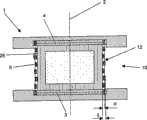
图3和4中示出本发明的椎间植入物1的一种实施形式,它包括两个横向于中心轴线2设置的盖板3、4和一个位于其中间的可弹性变形的中心部分10。中心部分10包括一个共轴于中心轴线2的空心圆柱形外壳12和一个中心腔11。在中心腔11中设置一个弹性的成型体9,其具有一个不可压缩的芯部,优选为一个液体芯部13。成型体9由一个半渗透的薄膜围绕,而外壳12由塑料制成,其包括纤维系统5和一个弹性的由纤维系统5通过的外壳体25。端接板14、15与盖板3、4固定连结并且具有轴向外表面16、17,它们可支承在两邻接的椎骨体的端板上。纤维系统5锚定在盖板3、4上并且结合于外壳12中,且并用于承受在中心部分10上的力,这些力通过邻接端接板14、15的椎骨体施加到椎间植入物1上,亦即通过椎骨体相互相对绕中心轴线2扭转的扭转力或通过脊椎柱的侧向弯曲和/或屈曲/伸展的弯矩。例如一个由两端接板14、15平行于中心轴线2在椎间植入物1上的压缩力经由两盖板3、4传到中心部分10上。从而以后弹性成型体9横向于中心轴线2膨胀。这样的弹性成型体9的膨胀运动传到包括纤维系统5的外壳12上并由其限制。由于纤维系统5锚定在盖板3、4上,横向于中心轴线2作用的压力在纤维系统5的各纤维上引起拉力。纤维系统5在这里由塑料纤维、优选由UHMWPE纤维(超高分子量聚乙烯)或由PET(聚对苯二甲酸乙二酯)构成并且包括第一和第二纤维6a、6b的编织层,它们相互交织。其中第一纤维6a与中心轴线2夹一个角度α而第二纤维6b与中心轴线2夹一个角度β。在图中所示的本发明的椎间植入物1的实施形式中,角度α和β是同样大小的并且在15°与60°之间。在盖板3、4上借助各槽18锚定纤维6a、6b,各槽平行于中心轴线2设置在盖板3、4的圆周上,从而纤维6a、6b通过槽18并且可以沿表面7、8在一个通道19内导向下一槽18。盖板3、4由塑料制成,而在外面设置的端接板14、15由钛或钛合金制成。在外面设置的端接板14、15与盖板3、4或形锁合或摩擦锁合相连结。特别是它们彼此间可以粘结或焊接。3 and 4 show an embodiment of the
图5a和5b中示出本发明的椎间植入物1的一个实施形式的一个纤维系统5,其中沿端板3、4延伸的各纤维6在盖板3、4的圆形表面7、8上构成各个弦。A
图6a和6b中示出本发明的椎间植入物1的一个实施形式的一个纤维系统5,其中沿端板3、4延伸的各纤维6在中心轴线2和端板3、4的极点处相交。A
相对于各纤维6的对顶线设置(图6a、6b),各纤维6作为弦(图5a、5b)沿端板3、4的表面7、8的引导具有以下优点:The guidance of the
-由于各纤维6的交叉点的改善的分布,特别在盖板3、4的外表面7、8与端接板14、15(图3和4)之间不会发生堆积;以及- due to the improved distribution of the crossing points of the
-纤维系统5借助于缠绕技术可以相对于中心轴线2对称地制造,其中可以将椎间植入物1固定于中心轴线2与盖板3、4之间的交点。The
图7中示出一种实施形式,其与图3和4中所示的实施形式的区别只在于,在中心部分10的周边上设置的外壳12包括一个弹性的由纤维系统5只部分地通过的外壳体25,其厚度α小于纤维系统5的径向厚度δ。An embodiment is shown in FIG. 7 which differs from the embodiment shown in FIGS. 3 and 4 only in that the
Claims (38)
Applications Claiming Priority (1)
| Application Number | Priority Date | Filing Date | Title |
|---|---|---|---|
| PCT/CH2003/000247WO2004089257A1 (en) | 2003-04-14 | 2003-04-14 | Intervertebral implant |
Publications (2)
| Publication Number | Publication Date |
|---|---|
| CN1774218A CN1774218A (en) | 2006-05-17 |
| CN100484499Ctrue CN100484499C (en) | 2009-05-06 |
Family
ID=33136741
Family Applications (1)
| Application Number | Title | Priority Date | Filing Date |
|---|---|---|---|
| CNB038263130AExpired - Fee RelatedCN100484499C (en) | 2003-04-14 | 2003-04-14 | Intervertebral implant |
Country Status (12)
| Country | Link |
|---|---|
| US (5) | US7429270B2 (en) |
| EP (1) | EP1626684B1 (en) |
| JP (1) | JP4240399B2 (en) |
| KR (1) | KR101007648B1 (en) |
| CN (1) | CN100484499C (en) |
| AT (1) | ATE381305T1 (en) |
| AU (1) | AU2003213975B2 (en) |
| BR (1) | BR0318245A (en) |
| CA (1) | CA2534169C (en) |
| DE (2) | DE20321645U1 (en) |
| ES (1) | ES2297133T3 (en) |
| WO (1) | WO2004089257A1 (en) |
Families Citing this family (135)
| Publication number | Priority date | Publication date | Assignee | Title |
|---|---|---|---|---|
| US20060129242A1 (en)* | 2001-12-28 | 2006-06-15 | Brian Bergeron | Pseudo arthrosis device |
| US6793678B2 (en) | 2002-06-27 | 2004-09-21 | Depuy Acromed, Inc. | Prosthetic intervertebral motion disc having dampening |
| ZA200506029B (en) | 2003-01-31 | 2006-10-25 | Spinalmotion Inc | Spinal Midline Indicator |
| WO2004066884A1 (en) | 2003-01-31 | 2004-08-12 | Spinalmotion, Inc. | Intervertebral prosthesis placement instrument |
| AU2004212942A1 (en) | 2003-02-14 | 2004-09-02 | Depuy Spine, Inc. | In-situ formed intervertebral fusion device |
| CN100484499C (en)* | 2003-04-14 | 2009-05-06 | 斯恩蒂斯有限公司 | Intervertebral implant |
| US7575599B2 (en) | 2004-07-30 | 2009-08-18 | Spinalmotion, Inc. | Intervertebral prosthetic disc with metallic core |
| US10052211B2 (en) | 2003-05-27 | 2018-08-21 | Simplify Medical Pty Ltd. | Prosthetic disc for intervertebral insertion |
| US7442211B2 (en) | 2003-05-27 | 2008-10-28 | Spinalmotion, Inc. | Intervertebral prosthetic disc |
| US20040267367A1 (en) | 2003-06-30 | 2004-12-30 | Depuy Acromed, Inc | Intervertebral implant with conformable endplate |
| US20050015150A1 (en)* | 2003-07-17 | 2005-01-20 | Lee Casey K. | Intervertebral disk and nucleus prosthesis |
| US7153325B2 (en)* | 2003-08-01 | 2006-12-26 | Ultra-Kinetics, Inc. | Prosthetic intervertebral disc and methods for using the same |
| EP2113227B1 (en) | 2004-02-04 | 2015-07-29 | LDR Medical | Intervertebral disc prosthesis |
| CA2813136A1 (en) | 2004-02-27 | 2005-09-15 | Aortx, Inc. | Prosthetic heart valve delivery systems and methods |
| US8636802B2 (en) | 2004-03-06 | 2014-01-28 | DePuy Synthes Products, LLC | Dynamized interspinal implant |
| WO2005094733A1 (en)* | 2004-04-02 | 2005-10-13 | Synthes Gmbh | Intervertebral disc prosthesis or artificial vertebral body |
| US7585326B2 (en) | 2004-08-06 | 2009-09-08 | Spinalmotion, Inc. | Methods and apparatus for intervertebral disc prosthesis insertion |
| WO2006078663A2 (en)* | 2005-01-19 | 2006-07-27 | Nexgen Spine, Inc. | Elastomeric intervertebral disc prosthesis |
| AU2006206559A1 (en)* | 2005-01-19 | 2006-07-27 | Nexgen Spine, Inc. | Fixation of elastomer to rigid structures |
| US8083797B2 (en) | 2005-02-04 | 2011-12-27 | Spinalmotion, Inc. | Intervertebral prosthetic disc with shock absorption |
| WO2006133130A2 (en)* | 2005-06-03 | 2006-12-14 | Nuvasive, Inc. | Fibrous spinal implant and method of implantation |
| US20070050032A1 (en)* | 2005-09-01 | 2007-03-01 | Spinal Kinetics, Inc. | Prosthetic intervertebral discs |
| EP1948041A2 (en)* | 2005-10-24 | 2008-07-30 | Nexgen Spine, Inc. | Intervertebral disc replacement and associated instrumentation |
| US7645301B2 (en)* | 2006-01-13 | 2010-01-12 | Zimmer Spine, Inc. | Devices and methods for disc replacement |
| US8038920B2 (en) | 2006-01-25 | 2011-10-18 | Carticept Medical, Inc. | Methods of producing PVA hydrogel implants and related devices |
| US8603171B2 (en)* | 2006-01-25 | 2013-12-10 | Mimedx Group, Inc. | Spinal disc implants with flexible keels and methods of fabricating implants |
| US20070179617A1 (en)* | 2006-01-25 | 2007-08-02 | Spinemedica Corporation | Prosthetic wide range motion facets and methods of fabricating same |
| US8182536B2 (en)* | 2006-02-01 | 2012-05-22 | Synthes Usa, Llc | Total disc replacement device |
| US8147541B2 (en) | 2006-02-27 | 2012-04-03 | Aortx, Inc. | Methods and devices for delivery of prosthetic heart valves and other prosthetics |
| US7749266B2 (en) | 2006-02-27 | 2010-07-06 | Aortx, Inc. | Methods and devices for delivery of prosthetic heart valves and other prosthetics |
| DE102006016986A1 (en)* | 2006-04-06 | 2007-10-18 | Aesculap Ag & Co. Kg | Intervertebral implant |
| WO2007121320A2 (en) | 2006-04-12 | 2007-10-25 | Spinalmotion, Inc. | Posterior spinal device and method |
| US20070276497A1 (en)* | 2006-05-23 | 2007-11-29 | Sdgi Holdings. Inc. | Surgical spacer |
| US8500799B2 (en) | 2006-06-20 | 2013-08-06 | Cardiacmd, Inc. | Prosthetic heart valves, support structures and systems and methods for implanting same |
| WO2007149933A2 (en) | 2006-06-21 | 2007-12-27 | Aortx, Inc. | Prosthetic valve implantation systems |
| WO2008039850A2 (en)* | 2006-09-26 | 2008-04-03 | Nexgen Spine, Inc. | Intervertebral. prosthesis endplate having double dome and surgical tools for preparing the vertebral body endplate to receive the prosthesis |
| US8403987B2 (en)* | 2006-09-27 | 2013-03-26 | Spinal Kinetics Inc. | Prosthetic intervertebral discs having compressible core elements bounded by fiber-containing membranes |
| WO2008070863A2 (en) | 2006-12-07 | 2008-06-12 | Interventional Spine, Inc. | Intervertebral implant |
| US7905922B2 (en)* | 2006-12-20 | 2011-03-15 | Zimmer Spine, Inc. | Surgical implant suitable for replacement of an intervertebral disc |
| US20080161928A1 (en)* | 2006-12-27 | 2008-07-03 | Warsaw Orthopedic, Inc. | Compliant intervertebral prosthetic devices with motion constraining tethers |
| WO2008088869A1 (en)* | 2007-01-19 | 2008-07-24 | Spinemedica Corporation | Methods and systems for forming implants with selectively exposed mesh for fixation |
| US20090118834A1 (en)* | 2007-04-01 | 2009-05-07 | Spinal Kinetics, Inc. | Expandable Prosthetic Intervertebral Discs That Are Implantable By Minimally Invasive Surgical Techniques |
| US20100286778A1 (en)* | 2007-04-18 | 2010-11-11 | Lukas Eisermann | Textile-Based Spinal Implant and Related Methods |
| US9173686B2 (en)* | 2007-05-09 | 2015-11-03 | Ebi, Llc | Interspinous implant |
| US9381047B2 (en) | 2007-05-09 | 2016-07-05 | Ebi, Llc | Interspinous implant |
| US8900307B2 (en) | 2007-06-26 | 2014-12-02 | DePuy Synthes Products, LLC | Highly lordosed fusion cage |
| US20090043391A1 (en) | 2007-08-09 | 2009-02-12 | Spinalmotion, Inc. | Customized Intervertebral Prosthetic Disc with Shock Absorption |
| WO2009034738A1 (en)* | 2007-09-10 | 2009-03-19 | Panasonic Corporation | Refrigerant compressor |
| US20090105834A1 (en) | 2007-10-22 | 2009-04-23 | Spinalmotion, Inc. | Dynamic Spacer Device and Method for Spanning a Space Formed upon Removal of an Intervertebral Disc |
| EP2237748B1 (en) | 2008-01-17 | 2012-09-05 | Synthes GmbH | An expandable intervertebral implant |
| DE202008001079U1 (en)* | 2008-01-25 | 2008-03-27 | Aesculap Ag & Co. Kg | Intervertebral implant |
| US8088163B1 (en) | 2008-02-06 | 2012-01-03 | Kleiner Jeffrey B | Tools and methods for spinal fusion |
| US8936641B2 (en) | 2008-04-05 | 2015-01-20 | DePuy Synthes Products, LLC | Expandable intervertebral implant |
| US9034038B2 (en) | 2008-04-11 | 2015-05-19 | Spinalmotion, Inc. | Motion limiting insert for an artificial intervertebral disc |
| EP2278941A1 (en) | 2008-05-05 | 2011-02-02 | Spinalmotion Inc. | Polyaryletherketone artificial intervertebral disc |
| US8470045B2 (en) | 2008-05-05 | 2013-06-25 | K2M, Inc. | Endplate for an intervertebral prosthesis and prosthesis incorporating the same |
| US20210378834A1 (en) | 2008-05-22 | 2021-12-09 | Spinal Surgical Strategies, Inc., A Nevada Corporation D/B/A Kleiner Device Labs | Spinal fusion cage system with inserter |
| US7976578B2 (en)* | 2008-06-04 | 2011-07-12 | James Marvel | Buffer for a human joint and method of arthroscopically inserting |
| US9220603B2 (en) | 2008-07-02 | 2015-12-29 | Simplify Medical, Inc. | Limited motion prosthetic intervertebral disc |
| EP2299944A4 (en) | 2008-07-17 | 2013-07-31 | Spinalmotion Inc | SYSTEM FOR INSTALLING ARTIFICIAL INTERVERTEBRAL DISCS |
| EP2299941A1 (en) | 2008-07-18 | 2011-03-30 | Spinalmotion Inc. | Posterior prosthetic intervertebral disc |
| USD853560S1 (en) | 2008-10-09 | 2019-07-09 | Nuvasive, Inc. | Spinal implant insertion device |
| US8366748B2 (en) | 2008-12-05 | 2013-02-05 | Kleiner Jeffrey | Apparatus and method of spinal implant and fusion |
| US8864654B2 (en) | 2010-04-20 | 2014-10-21 | Jeffrey B. Kleiner | Method and apparatus for performing retro peritoneal dissection |
| US9717403B2 (en) | 2008-12-05 | 2017-08-01 | Jeffrey B. Kleiner | Method and apparatus for performing retro peritoneal dissection |
| USD656610S1 (en) | 2009-02-06 | 2012-03-27 | Kleiner Jeffrey B | Spinal distraction instrument |
| US9247943B1 (en) | 2009-02-06 | 2016-02-02 | Kleiner Intellectual Property, Llc | Devices and methods for preparing an intervertebral workspace |
| US9526620B2 (en) | 2009-03-30 | 2016-12-27 | DePuy Synthes Products, Inc. | Zero profile spinal fusion cage |
| KR101687435B1 (en) | 2009-07-06 | 2016-12-19 | 신세스 게엠바하 | Expandable fixation assemblies |
| US9060877B2 (en) | 2009-09-18 | 2015-06-23 | Spinal Surgical Strategies, Llc | Fusion cage with combined biological delivery system |
| US8906028B2 (en) | 2009-09-18 | 2014-12-09 | Spinal Surgical Strategies, Llc | Bone graft delivery device and method of using the same |
| US8685031B2 (en) | 2009-09-18 | 2014-04-01 | Spinal Surgical Strategies, Llc | Bone graft delivery system |
| US20170238984A1 (en) | 2009-09-18 | 2017-08-24 | Spinal Surgical Strategies, Llc | Bone graft delivery device with positioning handle |
| US9186193B2 (en) | 2009-09-18 | 2015-11-17 | Spinal Surgical Strategies, Llc | Fusion cage with combined biological delivery system |
| US9629729B2 (en) | 2009-09-18 | 2017-04-25 | Spinal Surgical Strategies, Llc | Biological delivery system with adaptable fusion cage interface |
| USD723682S1 (en) | 2013-05-03 | 2015-03-03 | Spinal Surgical Strategies, Llc | Bone graft delivery tool |
| USD750249S1 (en) | 2014-10-20 | 2016-02-23 | Spinal Surgical Strategies, Llc | Expandable fusion cage |
| US10973656B2 (en) | 2009-09-18 | 2021-04-13 | Spinal Surgical Strategies, Inc. | Bone graft delivery system and method for using same |
| US9173694B2 (en) | 2009-09-18 | 2015-11-03 | Spinal Surgical Strategies, Llc | Fusion cage with combined biological delivery system |
| US10245159B1 (en) | 2009-09-18 | 2019-04-02 | Spinal Surgical Strategies, Llc | Bone graft delivery system and method for using same |
| US9393129B2 (en) | 2009-12-10 | 2016-07-19 | DePuy Synthes Products, Inc. | Bellows-like expandable interbody fusion cage |
| US8388656B2 (en)* | 2010-02-04 | 2013-03-05 | Ebi, Llc | Interspinous spacer with deployable members and related method |
| US9907560B2 (en) | 2010-06-24 | 2018-03-06 | DePuy Synthes Products, Inc. | Flexible vertebral body shavers |
| US8979860B2 (en) | 2010-06-24 | 2015-03-17 | DePuy Synthes Products. LLC | Enhanced cage insertion device |
| US8623091B2 (en) | 2010-06-29 | 2014-01-07 | DePuy Synthes Products, LLC | Distractible intervertebral implant |
| US20120078372A1 (en) | 2010-09-23 | 2012-03-29 | Thomas Gamache | Novel implant inserter having a laterally-extending dovetail engagement feature |
| US9402732B2 (en) | 2010-10-11 | 2016-08-02 | DePuy Synthes Products, Inc. | Expandable interspinous process spacer implant |
| US20120179258A1 (en)* | 2010-12-28 | 2012-07-12 | Paul Glazer | Spinal spacer devices, tools, and methods |
| US9358122B2 (en) | 2011-01-07 | 2016-06-07 | K2M, Inc. | Interbody spacer |
| US9248028B2 (en) | 2011-09-16 | 2016-02-02 | DePuy Synthes Products, Inc. | Removable, bone-securing cover plate for intervertebral fusion cage |
| US20130261746A1 (en)* | 2012-03-28 | 2013-10-03 | Linares Medical Devices, Llc | Implantable inter-vertebral disk having upper and lower layers of a metal exhibiting bone fusing characteristics and which sandwich therebetween a soft plastic cushioning disc for providing dynamic properties mimicking that of a natural inter-vertebral disc |
| EP2877127B1 (en) | 2012-07-26 | 2019-08-21 | Synthes GmbH | Expandable implant |
| EP3269335B1 (en)* | 2012-10-02 | 2019-03-06 | McCullen, Seth | Implantable devices for musculoskeletal repair and regeneration |
| US9717601B2 (en) | 2013-02-28 | 2017-08-01 | DePuy Synthes Products, Inc. | Expandable intervertebral implant, system, kit and method |
| US9522070B2 (en) | 2013-03-07 | 2016-12-20 | Interventional Spine, Inc. | Intervertebral implant |
| US20140277467A1 (en) | 2013-03-14 | 2014-09-18 | Spinal Stabilization Technologies, Llc | Prosthetic Spinal Disk Nucleus |
| EP3613386A1 (en) | 2014-10-02 | 2020-02-26 | McCullen, Seth | Anatomically designed meniscus implantable devices |
| WO2016073587A1 (en) | 2014-11-04 | 2016-05-12 | Spinal Stabilization Technologies Llc | Percutaneous implantable nuclear prosthesis |
| KR102464886B1 (en) | 2014-11-04 | 2022-11-08 | 스파이널 스태빌라이제이션 테크놀로지스, 엘엘씨 | Percutaneous implantable nuclear prosthesis |
| US11426290B2 (en) | 2015-03-06 | 2022-08-30 | DePuy Synthes Products, Inc. | Expandable intervertebral implant, system, kit and method |
| US10709570B2 (en) | 2015-04-29 | 2020-07-14 | Institute for Musculoskeletal Science and Education, Ltd. | Implant with a diagonal insertion axis |
| JP6768001B2 (en) | 2015-04-29 | 2020-10-14 | インスティテュート フォー マスキュロスケレタル サイエンス アンド エジュケイション,リミテッド | Coiled implants and systems and how to make them |
| US10492921B2 (en) | 2015-04-29 | 2019-12-03 | Institute for Musculoskeletal Science and Education, Ltd. | Implant with arched bone contacting elements |
| US10449051B2 (en) | 2015-04-29 | 2019-10-22 | Institute for Musculoskeletal Science and Education, Ltd. | Implant with curved bone contacting elements |
| US9913727B2 (en) | 2015-07-02 | 2018-03-13 | Medos International Sarl | Expandable implant |
| JP6891176B2 (en) | 2015-09-01 | 2021-06-18 | スパイナル スタビライゼーション テクノロジーズ リミテッド ライアビリティ カンパニー | Implantable nucleus pulposus prosthesis |
| USD797290S1 (en) | 2015-10-19 | 2017-09-12 | Spinal Surgical Strategies, Llc | Bone graft delivery tool |
| US10617531B2 (en) | 2015-10-26 | 2020-04-14 | K2M, Inc. | Cervical disc and instrumentation |
| EP3195833B1 (en) | 2016-01-19 | 2022-01-12 | K2M, Inc. | Surgical instrument |
| US10918494B2 (en) | 2016-04-26 | 2021-02-16 | K2M, Inc. | Orthopedic implant with integrated core |
| US11510788B2 (en) | 2016-06-28 | 2022-11-29 | Eit Emerging Implant Technologies Gmbh | Expandable, angularly adjustable intervertebral cages |
| EP3474784A2 (en) | 2016-06-28 | 2019-05-01 | Eit Emerging Implant Technologies GmbH | Expandable and angularly adjustable intervertebral cages with articulating joint |
| US10478312B2 (en) | 2016-10-25 | 2019-11-19 | Institute for Musculoskeletal Science and Education, Ltd. | Implant with protected fusion zones |
| US11033394B2 (en) | 2016-10-25 | 2021-06-15 | Institute for Musculoskeletal Science and Education, Ltd. | Implant with multi-layer bone interfacing lattice |
| US10537436B2 (en) | 2016-11-01 | 2020-01-21 | DePuy Synthes Products, Inc. | Curved expandable cage |
| US10888433B2 (en) | 2016-12-14 | 2021-01-12 | DePuy Synthes Products, Inc. | Intervertebral implant inserter and related methods |
| US10667924B2 (en) | 2017-03-13 | 2020-06-02 | Institute for Musculoskeletal Science and Education, Ltd. | Corpectomy implant |
| US10512549B2 (en) | 2017-03-13 | 2019-12-24 | Institute for Musculoskeletal Science and Education, Ltd. | Implant with structural members arranged around a ring |
| US10213317B2 (en) | 2017-03-13 | 2019-02-26 | Institute for Musculoskeletal Science and Education | Implant with supported helical members |
| US10357377B2 (en) | 2017-03-13 | 2019-07-23 | Institute for Musculoskeletal Science and Education, Ltd. | Implant with bone contacting elements having helical and undulating planar geometries |
| WO2018204440A2 (en) | 2017-05-02 | 2018-11-08 | Mccullen Seth | Composite joint implant |
| US10398563B2 (en) | 2017-05-08 | 2019-09-03 | Medos International Sarl | Expandable cage |
| US11344424B2 (en) | 2017-06-14 | 2022-05-31 | Medos International Sarl | Expandable intervertebral implant and related methods |
| US10940016B2 (en) | 2017-07-05 | 2021-03-09 | Medos International Sarl | Expandable intervertebral fusion cage |
| US10744001B2 (en) | 2017-11-21 | 2020-08-18 | Institute for Musculoskeletal Science and Education, Ltd. | Implant with improved bone contact |
| US10940015B2 (en) | 2017-11-21 | 2021-03-09 | Institute for Musculoskeletal Science and Education, Ltd. | Implant with improved flow characteristics |
| US10695192B2 (en) | 2018-01-31 | 2020-06-30 | Institute for Musculoskeletal Science and Education, Ltd. | Implant with internal support members |
| US10893951B2 (en) | 2018-08-07 | 2021-01-19 | Minimally Invasive Spinal Technology, LLC | Device and method for correcting spinal deformities in patients |
| CA3111639A1 (en) | 2018-09-04 | 2020-05-28 | Spinal Stabilization Technologies, Llc | Implantable nuclear prosthesis, kits, and related methods |
| US11446156B2 (en) | 2018-10-25 | 2022-09-20 | Medos International Sarl | Expandable intervertebral implant, inserter instrument, and related methods |
| CN110882093A (en)* | 2019-12-18 | 2020-03-17 | 上海畅迪医疗科技有限公司 | Artificial intervertebral disc |
| US11426286B2 (en) | 2020-03-06 | 2022-08-30 | Eit Emerging Implant Technologies Gmbh | Expandable intervertebral implant |
| US11850160B2 (en) | 2021-03-26 | 2023-12-26 | Medos International Sarl | Expandable lordotic intervertebral fusion cage |
| US11752009B2 (en) | 2021-04-06 | 2023-09-12 | Medos International Sarl | Expandable intervertebral fusion cage |
| US12090064B2 (en) | 2022-03-01 | 2024-09-17 | Medos International Sarl | Stabilization members for expandable intervertebral implants, and related systems and methods |
Citations (1)
| Publication number | Priority date | Publication date | Assignee | Title |
|---|---|---|---|---|
| CN2288707Y (en)* | 1997-03-05 | 1998-08-26 | 鲁继武 | Artificial intervertebral disc |
Family Cites Families (45)
| Publication number | Priority date | Publication date | Assignee | Title |
|---|---|---|---|---|
| SE391122B (en)* | 1971-01-25 | 1977-02-07 | Cutter Lab | PROTESTS IN THE FORM OF A SPINE BONIC DISC AND PROCEDURES FOR MANUFACTURE THEREOF |
| CH671691A5 (en)* | 1987-01-08 | 1989-09-29 | Sulzer Ag | |
| US4911718A (en)* | 1988-06-10 | 1990-03-27 | University Of Medicine & Dentistry Of N.J. | Functional and biocompatible intervertebral disc spacer |
| CH674928A5 (en)* | 1988-07-05 | 1990-08-15 | Experimentelle Chirurgie Lab | |
| AU624627B2 (en)* | 1988-08-18 | 1992-06-18 | Johnson & Johnson Orthopaedics, Inc. | Functional and biocompatible intervertebral disc spacer containing elastomeric material of varying hardness |
| US5545229A (en) | 1988-08-18 | 1996-08-13 | University Of Medicine And Dentistry Of Nj | Functional and biocompatible intervertebral disc spacer containing elastomeric material of varying hardness |
| CA1318469C (en)* | 1989-02-15 | 1993-06-01 | Acromed Corporation | Artificial disc |
| FR2659226B1 (en)* | 1990-03-07 | 1992-05-29 | Jbs Sa | PROSTHESIS FOR INTERVERTEBRAL DISCS AND ITS IMPLEMENTATION INSTRUMENTS. |
| US5192326A (en)* | 1990-12-21 | 1993-03-09 | Pfizer Hospital Products Group, Inc. | Hydrogel bead intervertebral disc nucleus |
| IE71172B1 (en) | 1991-03-25 | 1997-01-29 | Meadow Medicals Inc | Vascular prosthesis |
| GB9204263D0 (en)* | 1992-02-28 | 1992-04-08 | Limbs & Things Ltd | Artificial spinal disc |
| EP0566810B1 (en)* | 1992-04-21 | 1996-08-14 | SULZER Medizinaltechnik AG | Artificial spinal disc |
| EP0610837B1 (en)* | 1993-02-09 | 2001-09-05 | Acromed Corporation | Spine disc |
| US5571189A (en)* | 1994-05-20 | 1996-11-05 | Kuslich; Stephen D. | Expandable fabric implant for stabilizing the spinal motion segment |
| JPH0898850A (en)* | 1994-09-30 | 1996-04-16 | Kyocera Corp | Artificial disc |
| FR2747034B1 (en) | 1996-04-03 | 1998-06-19 | Scient X | INTERSOMATIC CONTAINMENT AND MERGER SYSTEM |
| US6120539A (en)* | 1997-05-01 | 2000-09-19 | C. R. Bard Inc. | Prosthetic repair fabric |
| US6682561B2 (en) | 1998-06-18 | 2004-01-27 | Pioneer Laboratories, Inc. | Spinal fixation system |
| DE29813139U1 (en) | 1998-07-23 | 1998-12-03 | Howmedica GmbH, 24232 Schönkirchen | Vertebral body reconstruction system |
| US6063121A (en)* | 1998-07-29 | 2000-05-16 | Xavier; Ravi | Vertebral body prosthesis |
| FR2787017B1 (en)* | 1998-12-11 | 2001-04-27 | Dimso Sa | INTERVERTEBRAL DISC PROSTHESIS WITH IMPROVED MECHANICAL BEHAVIOR |
| US7094239B1 (en) | 1999-05-05 | 2006-08-22 | Sdgi Holdings, Inc. | Screws of cortical bone and method of manufacture thereof |
| US6419704B1 (en)* | 1999-10-08 | 2002-07-16 | Bret Ferree | Artificial intervertebral disc replacement methods and apparatus |
| US6936071B1 (en) | 1999-07-02 | 2005-08-30 | Spine Solutions, Inc. | Intervertebral implant |
| US6533817B1 (en)* | 2000-06-05 | 2003-03-18 | Raymedica, Inc. | Packaged, partially hydrated prosthetic disc nucleus |
| CN1192750C (en) | 2000-08-28 | 2005-03-16 | 迪斯科动力学公司 | Prosthesis of vertebral disc |
| US6620196B1 (en)* | 2000-08-30 | 2003-09-16 | Sdgi Holdings, Inc. | Intervertebral disc nucleus implants and methods |
| US6733531B1 (en)* | 2000-10-20 | 2004-05-11 | Sdgi Holdings, Inc. | Anchoring devices and implants for intervertebral disc augmentation |
| US6827743B2 (en)* | 2001-02-28 | 2004-12-07 | Sdgi Holdings, Inc. | Woven orthopedic implants |
| DE50114038D1 (en)* | 2001-08-24 | 2008-07-31 | Zimmer Gmbh | Artificial disc |
| EP1287794B1 (en)* | 2001-08-24 | 2008-06-18 | Zimmer GmbH | Artificial spinal disc |
| US7025787B2 (en)* | 2001-11-26 | 2006-04-11 | Sdgi Holdings, Inc. | Implantable joint prosthesis and associated instrumentation |
| US7156848B2 (en)* | 2002-04-24 | 2007-01-02 | Ferree Bret A | Check reins for artificial disc replacements |
| US7066960B1 (en)* | 2002-06-28 | 2006-06-27 | Dickman Curtis A | Intervertebral disk replacement |
| EP1542626B1 (en)* | 2002-08-15 | 2012-09-26 | Synthes GmbH | Controlled artificial intervertebral disc implant |
| CA2495404C (en)* | 2002-08-15 | 2011-05-03 | Justin K. Coppes | Intervertebral disc implant |
| US6733533B1 (en)* | 2002-11-19 | 2004-05-11 | Zimmer Technology, Inc. | Artificial spinal disc |
| EP1605872B1 (en)* | 2003-03-24 | 2009-09-30 | Synthes GmbH | Vertebral disc or intervertebral disc prosthesis |
| US7060097B2 (en)* | 2003-03-31 | 2006-06-13 | Depuy Spine, Inc. | Method and apparatus for implant stability |
| US6893465B2 (en)* | 2003-03-31 | 2005-05-17 | Shi, Tain-Yew | Vividly simulated prosthetic intervertebral disc |
| CN100484499C (en) | 2003-04-14 | 2009-05-06 | 斯恩蒂斯有限公司 | Intervertebral implant |
| WO2004105655A1 (en)* | 2003-06-02 | 2004-12-09 | Impliant Ltd. | Spinal disc prosthesis |
| US7153325B2 (en)* | 2003-08-01 | 2006-12-26 | Ultra-Kinetics, Inc. | Prosthetic intervertebral disc and methods for using the same |
| WO2006078663A2 (en)* | 2005-01-19 | 2006-07-27 | Nexgen Spine, Inc. | Elastomeric intervertebral disc prosthesis |
| US20070270952A1 (en)* | 2006-04-19 | 2007-11-22 | Spinal Kinetics, Inc. | Prosthetic intervertebral discs implantable by minimally invasive surgical techniques |
- 2003
- 2003-04-14CNCNB038263130Apatent/CN100484499C/ennot_activeExpired - Fee Related
- 2003-04-14WOPCT/CH2003/000247patent/WO2004089257A1/enactiveIP Right Grant
- 2003-04-14USUS10/553,495patent/US7429270B2/ennot_activeExpired - Lifetime
- 2003-04-14KRKR1020057019479Apatent/KR101007648B1/ennot_activeExpired - Fee Related
- 2003-04-14DEDE20321645Upatent/DE20321645U1/ennot_activeExpired - Lifetime
- 2003-04-14ESES03709550Tpatent/ES2297133T3/ennot_activeExpired - Lifetime
- 2003-04-14AUAU2003213975Apatent/AU2003213975B2/ennot_activeCeased
- 2003-04-14CACA2534169Apatent/CA2534169C/ennot_activeExpired - Fee Related
- 2003-04-14JPJP2004570452Apatent/JP4240399B2/ennot_activeExpired - Lifetime
- 2003-04-14EPEP03709550Apatent/EP1626684B1/ennot_activeExpired - Lifetime
- 2003-04-14ATAT03709550Tpatent/ATE381305T1/ennot_activeIP Right Cessation
- 2003-04-14BRBRPI0318245-2Apatent/BR0318245A/ennot_activeApplication Discontinuation
- 2003-04-14DEDE50308869Tpatent/DE50308869D1/ennot_activeExpired - Lifetime
- 2008
- 2008-08-26USUS12/198,761patent/US20090054989A1/ennot_activeAbandoned
- 2010
- 2010-06-30USUS12/827,376patent/US8382838B2/ennot_activeExpired - Fee Related
- 2013
- 2013-01-03USUS13/733,336patent/US8690946B2/ennot_activeExpired - Lifetime
- 2014
- 2014-02-18USUS14/182,523patent/US9089439B2/ennot_activeExpired - Fee Related
Patent Citations (1)
| Publication number | Priority date | Publication date | Assignee | Title |
|---|---|---|---|---|
| CN2288707Y (en)* | 1997-03-05 | 1998-08-26 | 鲁继武 | Artificial intervertebral disc |
Also Published As
| Publication number | Publication date |
|---|---|
| BR0318245A (en) | 2006-04-04 |
| KR20060011832A (en) | 2006-02-03 |
| US20060265075A1 (en) | 2006-11-23 |
| CA2534169A1 (en) | 2004-10-21 |
| AU2003213975B2 (en) | 2008-06-26 |
| EP1626684A1 (en) | 2006-02-22 |
| US9089439B2 (en) | 2015-07-28 |
| ATE381305T1 (en) | 2008-01-15 |
| US20130138215A1 (en) | 2013-05-30 |
| JP2006522613A (en) | 2006-10-05 |
| US20140172108A1 (en) | 2014-06-19 |
| US20100280615A1 (en) | 2010-11-04 |
| KR101007648B1 (en) | 2011-01-13 |
| DE50308869D1 (en) | 2008-01-31 |
| CA2534169C (en) | 2010-10-12 |
| CN1774218A (en) | 2006-05-17 |
| US8382838B2 (en) | 2013-02-26 |
| JP4240399B2 (en) | 2009-03-18 |
| AU2003213975A1 (en) | 2004-11-01 |
| US20090054989A1 (en) | 2009-02-26 |
| DE20321645U1 (en) | 2008-08-21 |
| WO2004089257A1 (en) | 2004-10-21 |
| ES2297133T3 (en) | 2008-05-01 |
| EP1626684B1 (en) | 2007-12-19 |
| US7429270B2 (en) | 2008-09-30 |
| US8690946B2 (en) | 2014-04-08 |
Similar Documents
| Publication | Publication Date | Title |
|---|---|---|
| CN100484499C (en) | Intervertebral implant | |
| US6645248B2 (en) | Artificial intervertebral disc | |
| US10028839B2 (en) | Percutaneous implantable nuclear prosthesis | |
| US7201774B2 (en) | Artificial intervertebral disc replacements incorporating reinforced wall sections | |
| EP2635240B1 (en) | Anatomic total disc replacement | |
| US9278007B2 (en) | Prosthetic intervertebral discs having cast end plates and methods for making and using them | |
| US7597714B2 (en) | Inflatable nuclear prosthesis | |
| US7887592B2 (en) | Prosthetic intervertebral discs assemblies having compressible core elements with enhanced torque transmission | |
| NZ543464A (en) | ||
| US20080183292A1 (en) | Compliant intervertebral prosthetic devices employing composite elastic and textile structures | |
| US20030045940A1 (en) | Artificial intervertebral disc | |
| US20070067036A1 (en) | Hydrogel total disc prosthesis | |
| CN101442963A (en) | Mold assembly for intervertebral prosthesis | |
| US20060186588A1 (en) | Non-linear fiber/matrix architecture | |
| PL206907B1 (en) | Intervertebral implant | |
| ZA200507917B (en) | Intervertebral implant | |
| GB2395130A (en) | Intervertebral disc prosthesis | |
| CN101267783A (en) | Multi-composite disc prosthesis |
Legal Events
| Date | Code | Title | Description |
|---|---|---|---|
| C06 | Publication | ||
| PB01 | Publication | ||
| C10 | Entry into substantive examination | ||
| SE01 | Entry into force of request for substantive examination | ||
| C14 | Grant of patent or utility model | ||
| GR01 | Patent grant | ||
| CF01 | Termination of patent right due to non-payment of annual fee | ||
| CF01 | Termination of patent right due to non-payment of annual fee | Granted publication date:20090506 Termination date:20180414 |