CN100484429C - String holder - Google Patents
String holderDownload PDFInfo
- Publication number
- CN100484429C CN100484429CCNB2006101080475ACN200610108047ACN100484429CCN 100484429 CCN100484429 CCN 100484429CCN B2006101080475 ACNB2006101080475 ACN B2006101080475ACN 200610108047 ACN200610108047 ACN 200610108047ACN 100484429 CCN100484429 CCN 100484429C
- Authority
- CN
- China
- Prior art keywords
- plug
- socket
- cord
- opening
- pressing
- Prior art date
- Legal status (The legal status is an assumption and is not a legal conclusion. Google has not performed a legal analysis and makes no representation as to the accuracy of the status listed.)
- Expired - Fee Related
Links
Images


Classifications
- A—HUMAN NECESSITIES
- A44—HABERDASHERY; JEWELLERY
- A44B—BUTTONS, PINS, BUCKLES, SLIDE FASTENERS, OR THE LIKE
- A44B11/00—Buckles; Similar fasteners for interconnecting straps or the like, e.g. for safety belts
- A44B11/02—Buckles; Similar fasteners for interconnecting straps or the like, e.g. for safety belts frictionally engaging surface of straps
- A44B11/06—Buckles; Similar fasteners for interconnecting straps or the like, e.g. for safety belts frictionally engaging surface of straps with clamping devices
- F—MECHANICAL ENGINEERING; LIGHTING; HEATING; WEAPONS; BLASTING
- F16—ENGINEERING ELEMENTS AND UNITS; GENERAL MEASURES FOR PRODUCING AND MAINTAINING EFFECTIVE FUNCTIONING OF MACHINES OR INSTALLATIONS; THERMAL INSULATION IN GENERAL
- F16G—BELTS, CABLES, OR ROPES, PREDOMINANTLY USED FOR DRIVING PURPOSES; CHAINS; FITTINGS PREDOMINANTLY USED THEREFOR
- F16G11/00—Means for fastening cables or ropes to one another or to other objects; Caps or sleeves for fixing on cables or ropes
- F16G11/10—Quick-acting fastenings; Clamps holding in one direction only
- F16G11/101—Quick-acting fastenings; Clamps holding in one direction only deforming the cable by moving a part of the fastener
- A—HUMAN NECESSITIES
- A44—HABERDASHERY; JEWELLERY
- A44B—BUTTONS, PINS, BUCKLES, SLIDE FASTENERS, OR THE LIKE
- A44B11/00—Buckles; Similar fasteners for interconnecting straps or the like, e.g. for safety belts
- A44B11/25—Buckles; Similar fasteners for interconnecting straps or the like, e.g. for safety belts with two or more separable parts
- A44B11/26—Buckles; Similar fasteners for interconnecting straps or the like, e.g. for safety belts with two or more separable parts with push-button fastenings
- F—MECHANICAL ENGINEERING; LIGHTING; HEATING; WEAPONS; BLASTING
- F16—ENGINEERING ELEMENTS AND UNITS; GENERAL MEASURES FOR PRODUCING AND MAINTAINING EFFECTIVE FUNCTIONING OF MACHINES OR INSTALLATIONS; THERMAL INSULATION IN GENERAL
- F16G—BELTS, CABLES, OR ROPES, PREDOMINANTLY USED FOR DRIVING PURPOSES; CHAINS; FITTINGS PREDOMINANTLY USED THEREFOR
- F16G11/00—Means for fastening cables or ropes to one another or to other objects; Caps or sleeves for fixing on cables or ropes
- Y—GENERAL TAGGING OF NEW TECHNOLOGICAL DEVELOPMENTS; GENERAL TAGGING OF CROSS-SECTIONAL TECHNOLOGIES SPANNING OVER SEVERAL SECTIONS OF THE IPC; TECHNICAL SUBJECTS COVERED BY FORMER USPC CROSS-REFERENCE ART COLLECTIONS [XRACs] AND DIGESTS
- Y10—TECHNICAL SUBJECTS COVERED BY FORMER USPC
- Y10T—TECHNICAL SUBJECTS COVERED BY FORMER US CLASSIFICATION
- Y10T24/00—Buckles, buttons, clasps, etc.
- Y10T24/39—Cord and rope holders
- Y10T24/3969—Sliding part or wedge
- Y10T24/3973—Rope clamped between cone and socket
Landscapes
- Engineering & Computer Science (AREA)
- General Engineering & Computer Science (AREA)
- Mechanical Engineering (AREA)
- Buckles (AREA)
- Ropes Or Cables (AREA)
- Connector Housings Or Holding Contact Members (AREA)
Abstract
Translated fromChineseDescription
Translated fromChinese技术领域technical field
本发明涉及安装在绳带端部的绳带系紧用具。The present invention relates to a rope tie that is mounted on the end of a rope.
背景技术Background technique
现有的绳带用于各种各样的用途。例如,绳带多用于封闭鞋、提包或者衣服、装饰品中的开口部等或用于调整尺寸等。并且,绳带实际上用于连接物品或固定货物等各种各样的情况。Existing cords are used for a variety of purposes. For example, strings are often used to close openings in shoes, bags, clothes, and accessories, or to adjust sizes. Also, the straps are actually used in a variety of situations such as connecting items or securing goods.
另外,这里所说的绳带是可捆扎等的绳带状体的总称,除了一般的绳带、线、缆绳等以外也包括带子、皮带。In addition, the cord mentioned here is a generic term for cord-like objects that can be tied, etc., and includes tapes and belts in addition to general cords, threads, cables, and the like.
一般对这些绳带要进行端部处理。即,在单纯剪断的状态下不仅截面的外观或手感差,而且有时编织的材料会脱开。简单的端部处理例如有打结。并且,为了提高操作性、装饰性,安装有专用的绳带系紧用具。These cords are generally end-treated. That is, in a state of simple shearing, not only the appearance and texture of the cross section are poor, but also the woven material may come off. Simple end treatments such as knotting. In addition, in order to improve operability and decoration, a dedicated strap tie is installed.
作为绳带系紧用具开发了包入绳带的端部(从绳带的端部起一定长度的区域)的用具,可以省去在绳带上打结的麻烦。As a rope fastening tool, a tool that wraps the end of the rope (a region of a certain length from the end of the rope) has been developed, which can save the trouble of tying a knot on the rope.
具体是,将绳带的端部插入大致筒形的本体,从相反侧插入的锁定用具的突起部分以咬住绳带的端部的方式固定在绳带上(例如,参照专利文献1:特开平9-289906号公报(第4页、图1、图6))。Specifically, the end of the cord is inserted into the substantially cylindrical body, and the protruding portion of the locking tool inserted from the opposite side is fixed on the cord so as to bite the end of the cord (for example, refer to Patent Document 1: Special Kaiping No. 9-289906 Bulletin (page 4, Figure 1, Figure 6)).
并且,也有以下用具,即,具有凸元件和凹元件,将突起部分咬入绳带的方向作为与绳带交叉的方向,且使绳带的前端弯曲、以控制长度尺寸(例如,参照专利文献2:特开2002-17411号公报(第3~4页、图1~图3))。In addition, there is also a device that has a male element and a female element, the direction in which the protruding part bites into the rope is defined as a direction intersecting the rope, and the front end of the rope is bent to control the length (for example, refer to Patent Document 2: Japanese Patent Laid-Open No. 2002-17411 (
在上述的文献1和文献2中,由于是在插套(本体或凹元件)内设置锥形孔、将绳带固定在该锥形孔和插头(锁定用具或凸元件)的突起之间的结构,因此,一旦将插头插入插套,则由于插套的锥形孔,插入时的负荷逐渐增大,因此,具有不容易将插头插入插套并固定绳带的缺点。即,具有组装性差的缺点。In the above-mentioned
并且,一般在用针织材料覆盖绳带表面的情况下,突起部分钩在线圈上,可以得到良好的切入性,但近年来,在使用橡胶等的弹性体类作为芯件的绳带中,即使上述的突起部分要咬入,由于芯件容易变形,因此也得不到充分的切入性。In addition, in general, when the surface of the cord is covered with a knitted material, the protruding part is hooked on the loop, and good cutting performance can be obtained. However, in recent years, in cords using elastomers such as rubber as the core, even The above-mentioned protruding portion bites in, and since the core member is easily deformed, sufficient cutting performance cannot be obtained.
发明内容Contents of the invention
本发明的主要目的是提供组装性好、并且可以提高对绳带的固定性能的绳带系紧用具。The main object of the present invention is to provide a cord fastening tool which is easy to assemble and can improve the fixing performance of the cord.
本发明的绳带系紧用具具有可收容多个绳带端部的本体,其特征在于,所述本体具有大致筒形的插套和插入到所述插套内的插头,所述插套具有插入所述绳带端部的绳带用开口、插入所述插头的插头用开口、与所述绳带用开口和所述插头用开口连通且在规定长度上收容从所述绳带用开口插入的所述绳带端部的收容部、以及对收容在所述收容部内的所述绳带端部进行卡定的多个卡定部,在所述插套和插头中的任何一方上,设置可朝向所述各卡定部扩张、将所述绳带端部向所述卡定部按压的多根按压支脚部,在所述插套和插头中的另一方上,设置与所述按压支脚部抵接、随着所述插头的插入使所述按压支脚部朝向所述各卡定部扩张的扩张部。The rope fastening device of the present invention has a body capable of accommodating a plurality of rope ends, and is characterized in that the body has a substantially cylindrical socket and a plug inserted into the socket, and the socket has The cord opening for inserting the end portion of the cord, the plug opening for inserting the plug, communicates with the cord opening and the plug opening, and accommodates insertion from the cord opening over a predetermined length. The accommodating part of the end of the cord and the plurality of locking parts for locking the end of the cord accommodated in the accommodating part are provided on any one of the socket and the plug A plurality of pressing legs that can expand toward each of the locking parts and press the end of the cord to the locking parts are provided on the other side of the socket and the plug, which are connected to the pressing legs. The expansion part abuts against the expansion part that expands the pressing leg part toward each of the locking parts as the plug is inserted.
根据这样的结构,从插套的绳带用开口插入绳带端部、收容在收容部内,同时,从插套的插头用开口插入插头。在将插头插入插套,直到设置在上述插套和插头中的任何一方上的扩张部与设置在另一方上的按压支脚部抵接之前,按压支脚部都不扩张,因此插入负荷不会增大。因此,扩张部与按压支脚部抵接前插入负荷都不会增大,所以可以将插头圆滑地插入插套。因此组装性优异。According to such a configuration, the end of the cord is inserted from the opening for the cord of the socket to be accommodated in the accommodating portion, and at the same time, the plug is inserted from the opening for the plug of the socket. When the plug is inserted into the socket, until the expansion part provided on one of the above-mentioned socket and plug abuts against the pressing leg part provided on the other, the pressing leg part does not expand, so the insertion load does not increase. big. Therefore, the insertion load does not increase until the expansion portion abuts against the push leg portion, so that the plug can be smoothly inserted into the socket. Therefore, the assemblability is excellent.
其结果,通过向插套内插入插头,在扩张部与按压支脚部抵接之后,若进一步插入插头后,则扩张部使按压支脚部朝向设置在插套上的各卡定部扩张,因此,收容在收容部内的绳带端部被按压在卡定部上。此时,由于插头被插入插套,插头相对于插套的姿势稳定,因此,由扩张部进行的按压支脚部的扩张动作也可以稳定地进行。其结果,收容在收容部内的绳带端部以通过按压支脚部和卡定部夹持的状态被束缚,因此,可以提高对绳带的固定性能。As a result, when the plug is inserted into the socket, after the expansion part comes into contact with the pressing leg part, if the plug is further inserted, the expansion part expands the pressing leg part toward each locking part provided on the socket. The end of the string accommodated in the receiving portion is pressed against the locking portion. At this time, since the plug is inserted into the socket, the attitude of the plug relative to the socket is stable, and therefore, the expanding operation of the pressing leg portion by the expanding portion can also be performed stably. As a result, the end portion of the string accommodated in the receiving portion is restrained in a state of being sandwiched between the pressing leg portion and the locking portion, so that the fixing performance of the string can be improved.
在本发明的绳带系紧用具中,优选地,所述插头具有塞住所述插套的所述插头用开口的基部,和从该基部起一体地延伸、插入到所述插套的所述收容部内的按压部,在所述按压部上形成所述按压支脚部,在所述插套上形成所述扩张部。In the tether tightening tool of the present invention, preferably, the plug has a base that plugs the opening for the plug of the socket, and the plug integrally extends from the base and is inserted into the socket. As for the pressing part in the receiving part, the pressing leg part is formed on the pressing part, and the expansion part is formed on the socket.
根据这样的结构,由于插头具有塞住插套的插头用开口的基部和从该基部起一体地延伸的按压部,因此,可以利用基部塞住插套的插头用开口。因此,可形成良好的外观,同时,可防止灰尘等进入插套内。According to such a configuration, since the plug has a base for plugging the plug opening of the socket and a pressing portion integrally extending from the base, the plug opening of the socket can be plugged by the base. Therefore, a good appearance can be formed, and at the same time, dust and the like can be prevented from entering the socket.
并且,由于可朝向卡定部扩张的多个按压支脚部形成在插头侧,扩张部形成在插套侧,因此可容易进行制造。例如,一旦要在插套侧形成可扩张的多个按压支脚部,则必须在筒形的插套内部形成可扩张的多个按压支脚部,因此制造麻烦,但根据上述的结构可容易地进行制造。尤其是在利用树脂的注射模塑成型对其进行成形的情况下,由于金属模加工非常复杂,因此,具有需要工时的问题。Furthermore, since the plurality of pressing leg portions that can expand toward the locking portion are formed on the plug side, and the expansion portion is formed on the socket side, manufacturing can be facilitated. For example, once a plurality of expandable pressing leg parts are to be formed on the side of the socket, a plurality of expandable pressing leg parts must be formed inside the cylindrical socket, so manufacturing is troublesome, but according to the above-mentioned structure, it can be easily carried out. manufacture. In particular, when it is molded by injection molding of a resin, there is a problem that man-hours are required because mold processing is very complicated.
在本发明的绳带系紧用具中,优选地,所述按压支脚部形成在所述按压部的前端部,所述扩张部形成在所述插套的所述绳带用开口附近。In the tether tightening tool according to the present invention, preferably, the pressing leg portion is formed at a front end portion of the pressing portion, and the expanding portion is formed near the opening for the tether of the socket.
在此,插套的绳带用开口附近是指筒形的插套中心的绳带用开口侧。Here, the vicinity of the cord opening of the socket refers to the cord opening side at the center of the cylindrical socket.
根据这样的结构,在插头基本上插入到插套内的状态下,扩张部与按压支脚部抵接,但由于在此之前扩张部不与按压支脚部抵接,因此,对插头的插入不产生大的负荷。因此,组装性优异。According to such a structure, in the state where the plug is basically inserted into the socket, the expansion part abuts on the pressing leg part, but since the expansion part does not abut on the pressing leg part before then, the insertion of the plug does not occur. big load. Therefore, assemblability is excellent.
其结果,一旦形成插头基本上插入到插套内的状态,则扩张部将与按压支脚部抵接,使按压支脚部扩张。即,在插头基本上插入到插套内的状态下,由于插头相对于插套的姿势最为稳定,因此,按压支脚部的扩张动作也可以稳定地进行。因此,可用按压支脚部和卡定部确实地夹持绳带端部。As a result, once the plug is basically inserted into the socket, the expanding portion comes into contact with the pressing leg portion to expand the pressing leg portion. That is, when the plug is basically inserted into the socket, since the posture of the plug relative to the socket is the most stable, the expansion operation of the pressing leg portion can also be performed stably. Therefore, the end of the string can be securely held by the pressing leg portion and the locking portion.
此外,由于绳带端部在按压支脚部进行扩张动作之前不固定,并且,从开始进行扩张动作到将绳带端部固定到插套上为止的插头的动作距离较短,因此,绳带端部的位置也不会错位,可以稳定地固定。In addition, since the end of the cord is not fixed until the expansion action is performed by pressing the leg portion, and the action distance of the plug from the start of the expansion action to the fixing of the end of the cord to the socket is short, the end of the cord The position of the head will not be misaligned, and it can be fixed stably.
在本发明的绳带系紧用具中,优选地,所述扩张部形成为相对于所述插头向所述插套的插入方向、越朝向相反方向前端越细的形状。In the tether tightening tool according to the present invention, preferably, the expansion portion is formed in a shape that becomes thinner toward an opposite direction with respect to an insertion direction of the plug into the socket.
根据这样的结构,在将插头向插套插入、扩张部与按压支脚部抵接时,由于扩张部相对于插头的插入方向形成越朝向相反方向前部越细的形状,因此,可容易扩张按压支脚部。According to such a structure, when the plug is inserted into the socket and the expansion part comes into contact with the pressing leg part, since the expansion part has a shape that becomes thinner toward the opposite direction with respect to the insertion direction of the plug, it can be easily expanded and pressed. foot part.
在本发明的绳带系紧用具上,优选地,所述扩张部设置在所述多个卡定部之间。In the cord fastening tool of the present invention, preferably, the expansion part is arranged between the plurality of locking parts.
根据这样的结构,由于扩张部设置在上述多个卡定部之间,因此,按压支脚部从卡定部的中央按压绳带端部,所以可以用较强的夹持力夹持绳带端部。According to such a structure, since the expanding part is provided between the above-mentioned plurality of locking parts, the pressing leg part presses the end of the string from the center of the locking part, so the end of the string can be clamped with a strong clamping force. department.
在本发明的绳带系紧用具上,优选地,所述卡定部由随着朝向所述插套的中心而扩张的V槽构成。In the cord fastening tool of the present invention, preferably, the locking portion is formed of a V-groove expanding toward the center of the socket.
根据这样的结构,在通过按压支脚部将绳带端部向卡定部按压时,由于卡定部由V槽构成,因此,绳带端部的拔出阻力大,固定效果好。According to such a structure, when the end of the cord is pressed to the locking part by pressing the leg part, since the locking part is formed of a V groove, the pull-out resistance of the end of the cord is large and the fixing effect is good.
在本发明的绳带系紧用具中,优选地,所述插头具有临时固定所述绳带端部的临时固定部。In the tether tightening tool of the present invention, preferably, the plug has a temporary fixing portion temporarily fixing the end of the tether.
根据这样的结构,在将绳带端部从插套的绳带用开口插入、并穿过收容部使其从插头用开口突出后,将其临时固定在插头的临时固定部上。在该状态下,如果一面将绳带端部拉回、一面将插头插入插套的插头用开口,则可将绳带端部以规定的姿势收容在插套的收容部内。然后,由于通过按压支脚部将绳带端部按压在卡定部上,因此可期待可靠的固定。According to such a configuration, after inserting the end portion of the cord through the opening for the cord of the socket and protruding from the opening for the plug through the receiving portion, it is temporarily fixed to the temporary fixing portion of the plug. In this state, when the end of the cord is pulled back and the plug is inserted into the plug opening of the socket, the end of the cord can be accommodated in the housing portion of the socket in a predetermined posture. Then, since the end portion of the string is pressed against the locking portion by pressing the leg portion, reliable fixing can be expected.
在本发明的绳带系紧用具中,优选地,在所述插头的按压部上,形成所述按压支脚部的第一狭缝沿着所述插头的插入方向形成在前端部,同时,与所述第一狭缝大致正交的第二狭缝形成在根基部上,在被该第二狭缝分割的分割壁的一方的所述根基部侧形成切槽部,同时,在所述分割壁上突出形成隔着所述第二狭缝相对的夹持片,通过该相对的夹持片形成所述临时固定部。In the cord fastening tool of the present invention, preferably, on the pressing portion of the plug, the first slit forming the pressing leg portion is formed at the front end along the insertion direction of the plug, and at the same time, A second slit substantially perpendicular to the first slit is formed on the base portion, a notch portion is formed on the base portion side of one of the partition walls divided by the second slit, and at the same time, A clamping piece opposing to each other across the second slit is protruded from the wall, and the temporary fixing portion is formed by the opposing clamping piece.
根据这样的结构,由于在插头的按压部的前端部,沿着插头的插入方向形成用于形成按压脚片的第一狭缝,因此,可以通过第一狭缝使按压支脚部向相互打开的方向弹性变形,可确实地利用按压支脚部夹住绳带端部。并且,由于在形成有作为临时固定部的夹持片的分割壁的一方上形成切槽部,因此,即使绳带端部的粗细有变化,也可以通过分割壁的弹性变形,确实地夹住绳带端部。According to such a structure, since the first slit for forming the pressing leg piece is formed at the front end portion of the pressing portion of the plug along the insertion direction of the plug, the pressing leg portions can be opened to each other through the first slit. Elastically deforms in one direction, and the end of the cord can be firmly clamped by the pressing leg. In addition, since the notch is formed on one side of the dividing wall on which the clamping piece as the temporary fixing part is formed, even if the thickness of the end of the string changes, the elastic deformation of the dividing wall can securely clamp it. Rope ends.
附图说明Description of drawings
图1是表示本发明的实施方式的插套和插头的分解立体图。Fig. 1 is an exploded perspective view showing a socket and a plug according to an embodiment of the present invention.
图2是表示上述实施方式的插套的纵剖视图。Fig. 2 is a longitudinal sectional view showing the socket of the above embodiment.
图3是表示上述实施方式的插头的侧视图。Fig. 3 is a side view showing the plug of the above embodiment.
图4是表示将绳带端部临时固定在上述实施方式的插头上的状态的侧视图。Fig. 4 is a side view showing a state in which the end of the cord is temporarily fixed to the plug of the above embodiment.
图5是表示在上述实施方式中、将插头装入插套中的状态的纵剖视图。Fig. 5 is a longitudinal sectional view showing a state in which the plug is inserted into the socket in the above embodiment.
图6是表示在上述实施方式中、将插头插入插套之前的状态图。Fig. 6 is a diagram showing a state before the plug is inserted into the socket in the above embodiment.
图7是表示在上述实施方式中、插头即将与插套卡合的状态图。Fig. 7 is a diagram showing a state immediately before the plug is engaged with the socket in the above embodiment.
图8是表示在上述实施方式中、插头与插套卡合后的状态图。Fig. 8 is a diagram showing a state in which the plug and the socket are engaged in the above embodiment.
图9是图8的IX-IX线剖视图。Fig. 9 is a sectional view taken along line IX-IX of Fig. 8 .
图10是表示本发明的变形例的图。FIG. 10 is a diagram showing a modified example of the present invention.
图11是表示本发明的其它实施方式的分解立体图。Fig. 11 is an exploded perspective view showing another embodiment of the present invention.
图12是表示在上述其他实施方式中、将插头插入插套中的中途状态的剖视图。Fig. 12 is a sectional view showing a state in the middle of inserting the plug into the socket in the other embodiment described above.
图13是表示在上述其他实施方式中、将插头完全插入插套的组装状态的剖视图。Fig. 13 is a cross-sectional view showing an assembled state in which the plug is completely inserted into the socket in the other embodiment described above.
图14是表示上述其他实施方式中的组装状态的剖视图。FIG. 14 is a cross-sectional view showing an assembled state in another embodiment described above.
具体实施方式Detailed ways
以下根据附图就本发明的实施方式进行说明。Embodiments of the present invention will be described below with reference to the drawings.
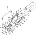
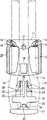
图1是表示构成本实施方式的绳带系紧用具2的插套10和插头20的分解立体图,图2是表示插套10的纵剖视图,图3是表示插头20的侧视图,图4是表示将绳带端部1A临时固定在插头20上的状态的侧视图,图5是表示组装插套10和插头20的状态的剖视图,图6是表示将插头20插入插套10之前的状态图,图7是表示插头20即将完全插入插套10的状态图,图8是表示插头20完全插入插套10后的状态图,图9是表示在插头20完全插入插套10后的状态下、对绳带端部进行卡定的状态图(图8的IX-IX线剖视图)。Fig. 1 is an exploded perspective view showing a
<结构说明><Structure Description>
如图1所示,本实施方式的绳带系紧用具2具有可收容弯曲成U字形的绳带1的两个绳带端部1A的本体3。As shown in FIG. 1 , the
绳带1例如在插通拉锁的滑块孔、弯曲成两段并将各绳带端部1A插入绳带系紧用具2的状态下进行使用(操作滑块时作为捏手(つまみ)使用)。另外,虽然与绳带1的剖面形状(例如,圆绳带或扁绳带)或材料等无关,但例如对橡胶绳带那样的减径率大的绳带可以发挥更大的效果。本体3具有大致扁平的长圆筒形的插套10和向该插套10内插入卡合的插头20。这些插套10和插头20例如作为合成树脂的注射模塑成形品而形成。The
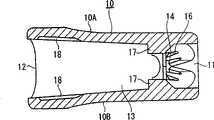
如图1、图2以及图5所示,插套10形成大致扁平的长圆筒形体,该大致扁平的长圆筒形体具有隔着间隙相对的直线壁10A、10B以及形成在其两端的圆弧壁10C、10D。在筒状体的一端形成插入绳带端部1A的绳带用开口11,在另一端形成插入插头20的插头用开口12,同时,在中间部形成与绳带用开口11和插头用开口12连通且沿规定长度收容从绳带用开口11插入的绳带端部1A的收容部13。As shown in FIGS. 1 , 2 and 5 , the
收容部13的相对于插头20的插入方向正交的方向的剖面形状,是与插头用开口12大致相同的形状,并且,沿插头20的插入方向形成大致相同的形状(大致扁平的长圆形状)。具体地说,圆弧壁10C、10D之间的尺寸在插头20的插入方向上是大致相同的尺寸,但直线壁10A、10B之间的尺寸形成随着朝向插头20的插入方向而逐渐变窄的锥筒形。The cross-sectional shape of the
在收容部13的绳带用开口11侧形成两个卡定部14,该卡定部14卡定被收容在收容部13内的两个绳带端部1A,同时,在该两个卡定部14的中间,在被夹在两个绳带端部1A之间的位置上形成扩张部17。Two locking
各卡定部14在绳带用开口11侧的圆弧壁10C、10D上作为V槽而形成。即,形成倾斜壁15,该倾斜壁15从圆弧壁10C、10D到达随着朝向收容部13的中心而相对的直线壁10A、10B的中央,在该倾斜壁15之间形成作为卡定部14的V槽。在倾斜壁15的V槽开口边缘上形成多个微小的V槽16,增加绳带端部1A的拔出阻力(切入性更高)。Each locking
扩张部17在两个卡定部14的中间,通过在直线壁10A、10B的内面上朝向中心突出形成的凸部而构成。凸部形成随着朝向插头20插入插套10的方向(插头插入方向、后述的按压支脚部24向收容部13内插进来的方向)的反方向前端逐渐变细的形状。The expanding
在收容部13的插头用开口12侧,在插头20插入到插套10内的规定位置时,具体是,在后述的插头20的按压部22插入插套10内时,形成与插头20卡合的卡合槽18。卡合槽18在插头用开口12侧的直线壁10A、10B内面的中央位置以一定的宽度形成规定的深度。卡合槽18的内侧台阶部形成在随着朝向绳带用开口11而向收容部13的中心倾斜的锥形壁上。On the plug opening 12 side of the receiving
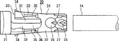
如图1、图3、图4和图5所示,插头20具有塞住插套10的插头用开口12的基部21,和从该基部21起一体延伸、插入插套10的收容部13内的按压部22。As shown in Fig. 1, Fig. 3, Fig. 4 and Fig. 5, the
基部21形成与插套10的插头用开口12嵌合的轮廓形状,即,厚度大致相同,从插头插入方向看的形状为大致扁平的长圆形状。The
在按压部22上,可朝向各卡定部14扩张、将绳带端部1A向卡定部14按压的一对按压支脚部24形成在前端侧,同时,具有临时固定绳带端部1A的可弹性变形的夹持片35的临时固定部36形成在根部。On the
具体是,从按压部22的中间位置起到前端,沿着插头20的插入方向形成用于分割形成两个按压支脚部24的第一狭缝23,同时,从按压部22的中间位置起到根部,形成与第一狭缝23大致正交的第二狭缝31。Specifically, from the middle position of the
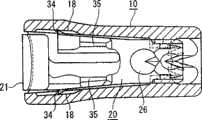
按压支脚部24的前端面,形成为随着朝向插头20的插入方向而向外侧倾斜的斜面25,即,形成为两个按压支脚部24的前端形状逐渐扩展的锥形面。在插头20向插套10插入大约一半以上时,在本实施方式的情况下,在插头20的被基本上插入插套10中时(在插头20的按压部22被插入插套10内时),该锥形面与扩张部17抵接。从该状态起如果进一步插入插头20,则随着该插头20的插入,按压支脚部24朝向各卡定部14扩张。并且,在按压支脚部24与第一狭缝23的相对面的相反侧面,设置有成为绳带端部的咬入突起的两个咬入突起26,在隔着该前端侧咬入突起26的两侧设置限制错位突起27。虽然咬入突起26形成圆锥形状,但其顶角形成为比圆锥形状的底面部更偏向按压部22的根部的形状。The front end surface of the
在由第二狭缝31分割的分割壁32的一方上,在与基部21之间形成切槽部33。在两个分割壁32上形成与插套10的卡合槽18嵌合的卡合钩34,同时,突出形成一对隔着第二切槽31相对的夹持片35。在该相对的夹持片35之间形成临时固定部36。卡合钩34在随着从两个分割壁32的外面起朝向基部21而逐渐向外方倾斜后,形成朝向中心形成为直角的剖面直角三角形状。夹持片35的内面,形成为随着从中间起朝向前端而逐渐向外侧倾斜的锥形面,这样,可容易将绳带端部1A向夹持片35之间插入。On one side of the
<组装方法的说明><explanation of the assembling method>
首先,如图6所示,从插套10的绳带用开口11插入绳带1的两个绳带端部1A,在穿过收容部13后从插头用开口12抽出,临时固定在插头20的临时固定部36上。具体是,将绳带端部1A插入插头20的夹持片35之间。此时,即使在绳带端部1A的粗细比夹持片35之间的间隔粗的情况下,由于两个分割壁32中的一方的设置有夹持片35的分割壁32可向外方弹性变形(由于通过切槽部33一方的分割壁32可向外方弹性变形),因此,通过用一对夹持片35卡定绳带端部1A,可进行临时固定。First, as shown in FIG. 6 , insert the two cord ends 1A of the
然后,如图7所示,一面用手指将基部21向插套10的方向按压,一面将绳带1从插套10中拔出,这样,随着插头20被插入插套10内,插头20的两个按压支脚部24向相互接近的方向弹性变形。即,由于两个绳带端部1A一面与插套10的卡定部14抵接一面被从插套10拔出,因此产生来自卡定部14的反作用力。这样,由于该反作用力通过绳带端部1A向两个按压支脚部24进行作用,因此,两个按压支脚部24向相互接近的方向弹性变形。该状态一直保持到插头20即将完全插入到插套10之前。因此,即使插头20插入到插套10中,由于直到插头20完全插入到插套10中之前,两个按压支脚部24向相互接近的方向弹性变形,因此,插头20插入时不会产生大的负荷。因此,可以将插头20圆滑地插入插套10。Then, as shown in FIG. 7 , while pressing the
其结果,将插头20插入插套10中,一旦插头20形成即将完全插入插套10中的状态,则插头20的按压支脚部24与插套10的扩张部17抵接。As a result, when the
从该状态起,将插头20进一步插入插套10,若插头20被完全插入插套10,则如图8所示,插头20的按压支脚部24向相互分离的方向弹性变形,朝向插套10的各卡定部14扩张。这样,收容在收容部13内的绳带端部1A被按压支脚部24向卡定部14按压。其结果,由于收容在收容部13内的绳带端部1A被卡定部14和按压支脚部24夹住,因此,绳带端部1A以被卡定部14和按压支脚部24夹住的状态进行束缚。From this state, the
此时,如图9所示,由于绳带端部1A由按压支脚部24和咬入突起26按压、被夹在卡定部14的V槽内,并形成咬入V槽的内周边缘的V槽16内的状态,因此,相对于拔出方向施加较大的阻力。并且,由于扩张部17位于卡定部14的中间,所以按压支脚部24从卡定部14的正侧面(大致中央)按压绳带端部1A,因此,可用强大的夹持力夹住绳带端部1A。并且,由于插头20的咬入突起26形成咬入绳带端部1A的状态,因此,可进行可靠的固定。At this time, as shown in FIG. 9, since the
<实施方式的效果><Effect of Embodiment>
(1)由于在插头20即将完全插入插套10之前,插头20的按压支脚部24都不与插套10的扩张部17抵接,因此,可将插头20圆滑地插入插套10。因此,在将插头20完全插入插套10之前,可以将插头20圆滑地插入插套10,因此组装性优良。(1) Before the
(2)由于插头20一旦形成即将完全插入插套10中的状态,则扩张部17将与按压支脚部24抵接,使按压支脚部24朝向卡定部14扩张,因此,收容在收容部13内的绳带端部1A被按压支脚部24向卡定部14按压。即,由于收容在收容部13内的绳带端部1A被卡定部14和按压支脚部24夹住,因此,绳带端部1A被束缚。所以,即使绳带1是减径率大的弹性材料等,也可以将绳带端部1A可靠地束缚在卡定部14内,可防止脱开等事故,因此,可以提高固定性能。(2) Once the
(3)插头20由于由塞住插套10的插头用开口12的基部21,和从该基部21起一体延伸、被插入插套10的收容部13内的按压部22构成,因此,可用插头20的基部21塞住插套10的插头用开口12。这样,不仅外观好而且可以防止灰尘等进入插套10内。(3) The
(4)由于在按压部22上形成可朝向卡定部14扩张的多个按压支脚部24,在插套10侧形成扩张部17,因此制造容易。例如,如果要在插套10侧形成可扩张的多个按压支脚部,则必须在该筒状的插套10的内部形成可扩张的多个按压支脚部,因此制造比较麻烦。相反,根据本实施方式的结构,则容易制造,尤其是在通过树脂的注射模塑成形形成按压支脚部的情况下,可以比较容易(与相反的结构相比容易)地进行金属模的加工。(4) Since the
(5)由于在按压部22的前端部形成按压支脚部24,在插套10的绳带用开口11附近形成扩张部17,因此,在处于插头20被基本插入到插套10中的状态时,扩张部17与按压支脚部24抵接,可以稳定地扩张按压支脚部24。即,在插头20基本被插入到插套10中的状态下,插头20相对于插套10的姿势稳定,因此可以稳定地扩张按压支脚部24。(5) Since the
(6)扩张部17形成随着朝向与插头20向插套10插入的方向的相反方向而前端越细的形状,因此,在将插头20插入插套10、扩张部17与按压支脚部24抵接时,容易使按压支脚部24扩张。(6) The
(7)扩张部17由于设置在两个卡定部14之间,因此,按压支脚部24从卡定部14的正侧面(大致中央)按压绳带端部1A,所以可用较强的夹持力夹住绳带端部1A。并且,由于插头20的咬入突起26形成咬入绳带端部1A的状态,因此可进行可靠的固定。(7) Since the
(8)插头20由于具有临时固定绳带端部1A的临时固定部36,因此,在从插套10的绳带用开口11插入绳带端部1A,并通过收容部13从插头用开口12突出后,临时固定在插头20的临时固定部36上。在该状态下,如果一面拉回绳带端部1A一面将插头20插入插套10的插头用开口12,则可以以稳定的姿势将绳带端部1A收容在插套10的收容部13内。然后,通过按压支脚部24将绳带端部1A按压在卡定部14上,因此,可期待可靠的固定。(8) Since the
(9)由于在插头20的按压部22的前端部沿着插头20的插入方向形成构成按压支脚部24的第一狭缝23,因此,可通过第一狭缝23使按压支脚部24向相互打开的方向弹性变形,按压支脚部24可切实地夹住绳带端部1A。并且,由于在形成了作为临时固定部36的夹持片35的两个分割壁32的一方上形成切槽部33,因此,即使绳带端部1A的粗细有变化,通过两个分割壁32的弹性变形,也可以切实地夹住绳带端部1A。(9) Since the
<变形例><Modification>
本发明并不局限于上述的实施方式,在可实现本发明的目的的范围内的变形、改良等都包括在本发明内。The present invention is not limited to the above-described embodiments, and modifications, improvements, and the like within the range in which the object of the present invention can be achieved are included in the present invention.
在上述实施方式中,在插头20上设置可朝向各卡定部14扩张、将绳带端部1A向卡定部14按压的多个按压支脚部24,在插套10上设置在插头20即将被完全插入插套10中之前与按压支脚部24抵接的扩张部17,但也可以进行相反的设置。In the above embodiment, the
即,也可以在插套10上设置多个按压支脚部24,在插头20上设置扩张部17。例如,在插套10的内部使多个按压支脚部24可相互接近且可分离地进行设置,同时,在插头20上设置使多个按压支脚部24向相互分离的方向分离的扩张部17,也可以期待同样的作用效果。That is, a plurality of
在上述实施方式中形成以下结构,即,在插头20即将完全插入插套10中之前,插头20的按压支脚部24与插套10的扩张部17抵接,然后,随着进一步插入插头20,按压支脚部24被扩张部17扩张,但也可以是以下的结构,即,至少在插头20相对于插套10插入大约一半以上时,插头20的按压支脚部24与插套10的扩张部17抵接,然后,随着插头20进一步的插入,按压支脚部24被扩张部17扩张。In the above-mentioned embodiment, the following structure is formed, that is, just before the
在上述实施方式中,将凸部形成在插套10的直线壁10A、10B的内面,将此作为扩张部17,但也不一定形成凸部。例如,如图10所示,也可以形成跨在插套10的直线壁10A、10B之间的隔壁41,将该隔壁41作为扩张部。总之,只要是可以使按压支脚部24朝向卡定部14扩张的结构,其他结构也可以。In the above-described embodiment, the convex portion is formed on the inner surface of the
在上述实施方式中,以对两个绳带端部1A进行端部处理的绳带系紧用具2为对象进行了说明,但也可以是对三个或三个以上的绳带端部(一条或多条绳带都可以)进行端部处理的绳带系紧用具。在这种情况下,设置在插套10上的卡定部14的数量或按压支脚部24的数量,也需要设置与绳带端部1A的数量相对应的数量。In the above-mentioned embodiment, the description has been made on the subject of the
在上述实施方式中形成以下结构,即,将卡合槽18设置在插套10上,同时,将卡合钩34设置在插头20上,在将插头20插入插套10中时,卡合钩34与卡合槽18卡合、使插头20不从插套10中脱落,但也不一定需要卡合槽18和卡合钩34。一旦形成通过卡定部14和按压支脚部24夹住绳带端部1A的状态,则插套10、插头20以及绳带端部1A通过该夹持力一体化,因此不一定需要卡合槽18和卡合钩34。In the above-mentioned embodiment, the following structure is formed, that is, the engaging
在上述实施方式中,在插头20的按压部22上设置了第二狭缝31,但也可以不设置第二狭缝31。即,可利用夹持片35本身的弹性固定绳带端部1A。而且,虽然在插头20上设置了临时固定部36,但也可以不专门设置临时固定部36。In the above-described embodiment, the
而且,在上述的实施方式或之后的变形例中,将扩张部17、41分别设置在插套10侧,将按压支脚部24和卡定部14设置在插头20侧,但也可以进行相反的设置。Furthermore, in the above-mentioned embodiment or subsequent modifications, the
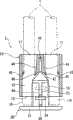
图11至图14表示本发明的其他实施方式。另外,在本实施方式中,绳带系紧用具2的基本结构(插套10、插头20等)与上述图1的实施方式相同。因此,通用的结构元件使用相同的符号,省略重复的说明。11 to 14 show other embodiments of the present invention. In addition, in this embodiment, the basic structure (
在图11中,插套10在一方侧具有两个绳带用开口11,可插入两根绳带1的端部(绳带端部1A)。在插套10上,在绳带用开口11的相反侧形成插头用开口12,通过插入该处的插头20,咬住并保持两条绳带端部1A。In FIG. 11, the
如图12至图14所示,在插套10的内部形成一对从两个绳带用开口11的边界部分起在收容部13内延伸的可弹性变形的按压支脚部44。在按压支脚部44的前端形成咬入突起46,在插套10的内壁部分形成卡定部45。这些卡定部45和咬入突起46相互相对设置,每对可分别夹住各绳带端部1A(参照图14)。As shown in FIGS. 12 to 14 , a pair of elastically deformable
插头20具有如覆盖插套10的插头用开口12那样的板状的基部21,和从该基部21起延伸的按压部22。在按压部22的前端形成插入到插套10内时的前端侧为前端变细形状的方锥形的扩张部47。因此,通过从插头用开口12向插套10内插入插头20(参照图12),前端的扩张部47挤入一对按压支脚部44之间的狭缝43内,使这些按压支脚部44向相互分离的方向变形(参照图13),将绳带端部1A夹持在卡定部45和咬入突起46之间,可以对其进行固定。The
另外,通过按压部22的前端的扩张部47和按压支脚部44之间的狭缝43,引导将插头20插入插套10中时的插头20的方向。而且,在按压部22的基端部分上形成三角锥形的引导部48,在插套10的内侧、在插头用开口12的边缘形成台阶差状的被引导部49。这些引导部48和被引导部49在将插头20插入插套10中时相互卡合,可将插头20相对于插套10向规定的位置进行引导。通过这些引导部48和被引导部49,对于插头20和插套10,在将插头20插入插套10的操作中可进行适当的引导,可形成图13所示的组装状态。In addition, the direction of the
在扩张部47的中间形成卡合钩34,在插套10的内壁上形成卡合槽18。通过这些卡合钩34和卡合槽18,在将插头20插入插套10中时,这些卡合钩34和卡合槽18相互卡合,可保持图13所示的绳带系紧用具2的组装状态。An engaging
就这样的本实施方式中的动作进行说明。The operation in this embodiment will be described.
首先,如图11所示,将两条绳带端部1A(可以是一条绳带1的两个端部,也可是两条绳带1的各端部)对齐,并分别插入插套10的绳带用开口11,将各绳带端部1A一直送入插头用开口12(参照图12)。然后,使插头20对准插头用开口12,将按压部22向插头用开口12内插入。通过该插入,按压部22进入插套10内,形成前端变细形状的前端的扩张部47挤入狭缝43内,使位于两根绳带端部1A的边界部分的一对按压支脚部44向相互分开的方向变形,通过该变形,卡定部45和咬入突起46夹持各绳带端部1A(参照图13)。然后,若按压部22向插套10内进入到规定的深度,则卡合钩34和卡合槽18相互卡合,插套10、插头20以及绳带1保持为图13所示的状态。First, as shown in Figure 11, align the
根据图11至图14的实施方式也可以得到本发明的独特的效果。The unique effect of the present invention can also be obtained according to the embodiments of FIGS. 11 to 14 .
上述各实施方式中的具体的形状、材质以及结构等,在保持各部的功能的范围内可以进行适当的变化。是一体形成各部分还是单独形成后再进行接合等,在实施时刻进行适当的选择。The specific shapes, materials, structures, and the like in each of the above-described embodiments can be appropriately changed within the range of maintaining the functions of each part. Whether each part is formed integrally or separately formed and joined together is appropriately selected at the time of implementation.
在上述实施方式中,就适用于拉锁的滑块操作用绳带的绳带系紧用具为例进行了说明,但本发明并不局限于此,也可以作为其他的绳带的端部处理用的系紧用具进行使用。In the above-mentioned embodiment, the string fastening tool applied to the slider operating string of the zipper was described as an example, but the present invention is not limited thereto, and it can also be used as an end treatment for other strings. use the fastening device.
Claims (8)
Applications Claiming Priority (2)
| Application Number | Priority Date | Filing Date | Title |
|---|---|---|---|
| JP2005215709 | 2005-07-26 | ||
| JP2005215709AJP4528687B2 (en) | 2005-07-26 | 2005-07-26 | Tie fastener |
Publications (2)
| Publication Number | Publication Date |
|---|---|
| CN1903095A CN1903095A (en) | 2007-01-31 |
| CN100484429Ctrue CN100484429C (en) | 2009-05-06 |
Family
ID=37670189
Family Applications (1)
| Application Number | Title | Priority Date | Filing Date |
|---|---|---|---|
| CNB2006101080475AExpired - Fee RelatedCN100484429C (en) | 2005-07-26 | 2006-07-26 | String holder |
Country Status (6)
| Country | Link |
|---|---|
| US (1) | US7574779B2 (en) |
| JP (1) | JP4528687B2 (en) |
| KR (1) | KR100713768B1 (en) |
| CN (1) | CN100484429C (en) |
| DE (1) | DE102006034367B4 (en) |
| TW (1) | TWI299981B (en) |
Families Citing this family (25)
| Publication number | Priority date | Publication date | Assignee | Title |
|---|---|---|---|---|
| JP2009018004A (en)* | 2007-07-11 | 2009-01-29 | Maazen Products:Kk | String lock |
| JP2009018003A (en)* | 2007-07-11 | 2009-01-29 | Maazen Products:Kk | String lock |
| US20100050394A1 (en)* | 2008-09-02 | 2010-03-04 | Fried Brian A | Releasable Pull Tie |
| WO2010102131A1 (en) | 2009-03-04 | 2010-09-10 | The United States Of America As Represented By The Secretary, Department Of Health And Human Services | Tensioning device and methods for use |
| CN201518804U (en)* | 2009-09-11 | 2010-07-07 | 哈拉尔德柏哲公司 | Lock fastener for connecting two ends of textile tape |
| DE112009005405B4 (en) | 2009-11-30 | 2021-08-26 | Ykk Corporation | Cord fastener |
| JP5580431B2 (en)* | 2009-12-17 | 2014-08-27 | ボーグワーナー インコーポレーテッド | Turbocharger |
| KR200458951Y1 (en)* | 2010-02-19 | 2012-03-21 | 박대심 | bolo tie |
| JP5539475B2 (en)* | 2011-12-26 | 2014-07-02 | キヤノン株式会社 | Electronics |
| US20140215774A1 (en)* | 2013-02-01 | 2014-08-07 | Precision Dynamics Corporation | Fabric band closure |
| JP3190565U (en)* | 2014-02-25 | 2014-05-15 | Ykk株式会社 | String clip with hook |
| US9204700B1 (en)* | 2014-07-31 | 2015-12-08 | Shih-Ling Hsu | Hair styling device and creation method thereof |
| US10039347B2 (en)* | 2016-01-20 | 2018-08-07 | Nike, Inc. | Fastening mechanism for use with a lacing element |
| US9814281B2 (en)* | 2016-02-12 | 2017-11-14 | Bell Sports, Inc. | Combination shoelace and hook and loop fasteners shoe tightening system with replaceable shoelaces |
| JP6482496B2 (en) | 2016-05-19 | 2019-03-13 | 株式会社ニフコ | String terminal cover |
| US11026472B2 (en) | 2016-07-22 | 2021-06-08 | Nike, Inc. | Dynamic lacing system |
| CN106438843A (en)* | 2016-11-30 | 2017-02-22 | 南京海獭软件有限责任公司 | Steel wire butt joint connecting device |
| JP7083697B2 (en)* | 2018-05-15 | 2022-06-13 | Ykk株式会社 | Cord stopper |
| WO2020051278A1 (en) | 2018-09-06 | 2020-03-12 | Nike Innovate C.V. | Dynamic lacing system with feedback mechanism |
| US20200248781A1 (en)* | 2019-02-01 | 2020-08-06 | Craig W. Patterson | Cinching device |
| US10982731B2 (en)* | 2019-09-06 | 2021-04-20 | Innovative Product Solutions, LLC | Bungee loop retention assemblies |
| GB2591295B (en)* | 2020-01-27 | 2022-08-17 | Absolute Museum & Gallery Products Ltd | Improvements relating to barrier stands |
| US11612227B2 (en)* | 2020-02-28 | 2023-03-28 | Kiyawmi Thioub | Apparatus securable to flexible strand(s) |
| JP7696846B2 (en)* | 2022-01-24 | 2025-06-23 | Ykk株式会社 | Code End |
| TWI805481B (en)* | 2022-09-12 | 2023-06-11 | 台灣扣具工業股份有限公司 | Buckle assembly for rope tail and male buckle thereof |
Citations (2)
| Publication number | Priority date | Publication date | Assignee | Title |
|---|---|---|---|---|
| CN1097967A (en)* | 1993-05-07 | 1995-02-01 | 吉田工业株式会社 | Buckle |
| CN1310970A (en)* | 2000-03-03 | 2001-09-05 | 约瑟夫·安什尔 | High security buckle device |
Family Cites Families (22)
| Publication number | Priority date | Publication date | Assignee | Title |
|---|---|---|---|---|
| US2573806A (en)* | 1948-12-23 | 1951-11-06 | Adeline E E Paterson | Unidirectional restraining device for a fastening cord |
| US3897161A (en)* | 1974-01-16 | 1975-07-29 | Illinois Tool Works | Rope lock device |
| US3965544A (en)* | 1975-06-11 | 1976-06-29 | Boden Ogden W | Locking device with combined wedging and spring action |
| US4102019A (en)* | 1977-03-07 | 1978-07-25 | Boden Ogden W | Locking assemblies which maintain bow loops in cords |
| US4156574A (en)* | 1978-02-06 | 1979-05-29 | Boden Ogden W | Cord lock with self locking spring feelers |
| US4455717A (en)* | 1982-09-22 | 1984-06-26 | Gray Robert C | Rope clamping device |
| JPH0329635Y2 (en)* | 1984-11-08 | 1991-06-24 | ||
| JPH026812Y2 (en)* | 1986-03-03 | 1990-02-19 | ||
| JPS63281959A (en)* | 1987-05-07 | 1988-11-18 | Yonemushi Takeishi | Seal jig for coin-containing bag |
| JPH0739406A (en)* | 1993-07-30 | 1995-02-10 | Ykk Kk | Tie |
| JP3412659B2 (en)* | 1995-06-22 | 2003-06-03 | ワイケイケイ株式会社 | Long object connector |
| JPH09289906A (en) | 1996-04-26 | 1997-11-11 | Nifco Inc | End part holder |
| JPH1014620A (en) | 1996-07-01 | 1998-01-20 | Airisu:Kk | Braid stopping tool |
| US5903959A (en)* | 1997-11-24 | 1999-05-18 | Leonardi; David P. | Fastener for retaining shoe laces and drawstrings |
| JP4305693B2 (en)* | 1999-04-26 | 2009-07-29 | 株式会社ニフコ | Tie buckle |
| JP4473984B2 (en)* | 1999-08-26 | 2010-06-02 | 株式会社ニフコ | String terminal cover |
| US6415482B1 (en) | 2000-06-23 | 2002-07-09 | Illinois Tool Works Inc. | Attachment for zipper cord |
| US6457214B1 (en)* | 2000-10-13 | 2002-10-01 | Robert O. Boden | Tamper-resistant cord lock apparatus |
| JP3884692B2 (en)* | 2002-10-11 | 2007-02-21 | Ykk株式会社 | String fixing tool |
| JP4040451B2 (en)* | 2002-12-24 | 2008-01-30 | 株式会社ニフコ | End cover of string or band |
| JP2005211302A (en) | 2004-01-29 | 2005-08-11 | Ykk Corp | Tie fastener |
| JP4496099B2 (en)* | 2005-01-28 | 2010-07-07 | Ykk株式会社 | Tie fastener |
- 2005
- 2005-07-26JPJP2005215709Apatent/JP4528687B2/ennot_activeExpired - Fee Related
- 2006
- 2006-07-20USUS11/490,352patent/US7574779B2/ennot_activeExpired - Fee Related
- 2006-07-24TWTW095126971Apatent/TWI299981B/ennot_activeIP Right Cessation
- 2006-07-25KRKR1020060069417Apatent/KR100713768B1/ennot_activeExpired - Fee Related
- 2006-07-25DEDE102006034367Apatent/DE102006034367B4/ennot_activeExpired - Fee Related
- 2006-07-26CNCNB2006101080475Apatent/CN100484429C/ennot_activeExpired - Fee Related
Patent Citations (2)
| Publication number | Priority date | Publication date | Assignee | Title |
|---|---|---|---|---|
| CN1097967A (en)* | 1993-05-07 | 1995-02-01 | 吉田工业株式会社 | Buckle |
| CN1310970A (en)* | 2000-03-03 | 2001-09-05 | 约瑟夫·安什尔 | High security buckle device |
Also Published As
| Publication number | Publication date |
|---|---|
| US7574779B2 (en) | 2009-08-18 |
| US20070022575A1 (en) | 2007-02-01 |
| JP4528687B2 (en) | 2010-08-18 |
| TWI299981B (en) | 2008-08-21 |
| KR20070014032A (en) | 2007-01-31 |
| KR100713768B1 (en) | 2007-05-04 |
| CN1903095A (en) | 2007-01-31 |
| DE102006034367A1 (en) | 2007-02-08 |
| JP2007029343A (en) | 2007-02-08 |
| TW200716010A (en) | 2007-05-01 |
| DE102006034367B4 (en) | 2013-03-28 |
Similar Documents
| Publication | Publication Date | Title |
|---|---|---|
| CN100484429C (en) | String holder | |
| JP3416437B2 (en) | String end stopper | |
| CN1102035C (en) | Buckle | |
| CN100548171C (en) | strap buckle | |
| US4872242A (en) | Flexible C-shaped strap-like connector | |
| TWI243655B (en) | Buckle | |
| US10588383B2 (en) | Buckle | |
| CN112515298A (en) | Rope stopping tool | |
| CN109152454A (en) | Sling | |
| CN102639023B (en) | Cord fastener | |
| TWI770403B (en) | Cable tie | |
| EP1388301B1 (en) | Buckle | |
| US20100284761A1 (en) | Press Type Fastener | |
| TW201024499A (en) | Cord end stopper | |
| CN112298799B (en) | Binding belt structure | |
| JP5355806B1 (en) | String lock | |
| JPH09289906A (en) | End part holder | |
| JP2000116412A (en) | Buckle | |
| JP7696846B2 (en) | Code End | |
| CN210227127U (en) | a zipper | |
| CN104860256B (en) | Rope clamp with hook | |
| CN111409953A (en) | Binding belt structure | |
| KR100486163B1 (en) | A clip for fixing papers | |
| JP2006250243A (en) | String end stopper | |
| JPH0627613U (en) | cable tie |
Legal Events
| Date | Code | Title | Description |
|---|---|---|---|
| C06 | Publication | ||
| PB01 | Publication | ||
| C10 | Entry into substantive examination | ||
| SE01 | Entry into force of request for substantive examination | ||
| C14 | Grant of patent or utility model | ||
| GR01 | Patent grant | ||
| CF01 | Termination of patent right due to non-payment of annual fee | ||
| CF01 | Termination of patent right due to non-payment of annual fee | Granted publication date:20090506 Termination date:20180726 |