CN100483787C - Method of fabricating an el display device, and apparatus for forming a thin film - Google Patents
Method of fabricating an el display device, and apparatus for forming a thin filmDownload PDFInfo
- Publication number
- CN100483787C CN100483787CCNB200410102249XACN200410102249ACN100483787CCN 100483787 CCN100483787 CCN 100483787CCN B200410102249X ACNB200410102249X ACN B200410102249XACN 200410102249 ACN200410102249 ACN 200410102249ACN 100483787 CCN100483787 CCN 100483787C
- Authority
- CN
- China
- Prior art keywords
- chamber
- electrode
- layer
- processing chamber
- substrate
- Prior art date
- Legal status (The legal status is an assumption and is not a legal conclusion. Google has not performed a legal analysis and makes no representation as to the accuracy of the status listed.)
- Expired - Fee Related
Links
Images


Classifications
- H—ELECTRICITY
- H01—ELECTRIC ELEMENTS
- H01L—SEMICONDUCTOR DEVICES NOT COVERED BY CLASS H10
- H01L21/00—Processes or apparatus adapted for the manufacture or treatment of semiconductor or solid state devices or of parts thereof
- H01L21/67—Apparatus specially adapted for handling semiconductor or electric solid state devices during manufacture or treatment thereof; Apparatus specially adapted for handling wafers during manufacture or treatment of semiconductor or electric solid state devices or components ; Apparatus not specifically provided for elsewhere
- H01L21/67005—Apparatus not specifically provided for elsewhere
- H01L21/67011—Apparatus for manufacture or treatment
- H01L21/67155—Apparatus for manufacturing or treating in a plurality of work-stations
- H01L21/67161—Apparatus for manufacturing or treating in a plurality of work-stations characterized by the layout of the process chambers
- H01L21/67167—Apparatus for manufacturing or treating in a plurality of work-stations characterized by the layout of the process chambers surrounding a central transfer chamber
- H—ELECTRICITY
- H10—SEMICONDUCTOR DEVICES; ELECTRIC SOLID-STATE DEVICES NOT OTHERWISE PROVIDED FOR
- H10F—INORGANIC SEMICONDUCTOR DEVICES SENSITIVE TO INFRARED RADIATION, LIGHT, ELECTROMAGNETIC RADIATION OF SHORTER WAVELENGTH OR CORPUSCULAR RADIATION
- H10F55/00—Radiation-sensitive semiconductor devices covered by groups H10F10/00, H10F19/00 or H10F30/00 being structurally associated with electric light sources and electrically or optically coupled thereto
- C—CHEMISTRY; METALLURGY
- C23—COATING METALLIC MATERIAL; COATING MATERIAL WITH METALLIC MATERIAL; CHEMICAL SURFACE TREATMENT; DIFFUSION TREATMENT OF METALLIC MATERIAL; COATING BY VACUUM EVAPORATION, BY SPUTTERING, BY ION IMPLANTATION OR BY CHEMICAL VAPOUR DEPOSITION, IN GENERAL; INHIBITING CORROSION OF METALLIC MATERIAL OR INCRUSTATION IN GENERAL
- C23C—COATING METALLIC MATERIAL; COATING MATERIAL WITH METALLIC MATERIAL; SURFACE TREATMENT OF METALLIC MATERIAL BY DIFFUSION INTO THE SURFACE, BY CHEMICAL CONVERSION OR SUBSTITUTION; COATING BY VACUUM EVAPORATION, BY SPUTTERING, BY ION IMPLANTATION OR BY CHEMICAL VAPOUR DEPOSITION, IN GENERAL
- C23C14/00—Coating by vacuum evaporation, by sputtering or by ion implantation of the coating forming material
- C23C14/22—Coating by vacuum evaporation, by sputtering or by ion implantation of the coating forming material characterised by the process of coating
- C23C14/56—Apparatus specially adapted for continuous coating; Arrangements for maintaining the vacuum, e.g. vacuum locks
- C23C14/568—Transferring the substrates through a series of coating stations
- H—ELECTRICITY
- H01—ELECTRIC ELEMENTS
- H01L—SEMICONDUCTOR DEVICES NOT COVERED BY CLASS H10
- H01L21/00—Processes or apparatus adapted for the manufacture or treatment of semiconductor or solid state devices or of parts thereof
- H01L21/67—Apparatus specially adapted for handling semiconductor or electric solid state devices during manufacture or treatment thereof; Apparatus specially adapted for handling wafers during manufacture or treatment of semiconductor or electric solid state devices or components ; Apparatus not specifically provided for elsewhere
- H01L21/67005—Apparatus not specifically provided for elsewhere
- H01L21/67011—Apparatus for manufacture or treatment
- H01L21/67155—Apparatus for manufacturing or treating in a plurality of work-stations
- H01L21/67161—Apparatus for manufacturing or treating in a plurality of work-stations characterized by the layout of the process chambers
- H01L21/67173—Apparatus for manufacturing or treating in a plurality of work-stations characterized by the layout of the process chambers in-line arrangement
- H—ELECTRICITY
- H01—ELECTRIC ELEMENTS
- H01L—SEMICONDUCTOR DEVICES NOT COVERED BY CLASS H10
- H01L21/00—Processes or apparatus adapted for the manufacture or treatment of semiconductor or solid state devices or of parts thereof
- H01L21/67—Apparatus specially adapted for handling semiconductor or electric solid state devices during manufacture or treatment thereof; Apparatus specially adapted for handling wafers during manufacture or treatment of semiconductor or electric solid state devices or components ; Apparatus not specifically provided for elsewhere
- H01L21/67005—Apparatus not specifically provided for elsewhere
- H01L21/67011—Apparatus for manufacture or treatment
- H01L21/67155—Apparatus for manufacturing or treating in a plurality of work-stations
- H01L21/67184—Apparatus for manufacturing or treating in a plurality of work-stations characterized by the presence of more than one transfer chamber
- H—ELECTRICITY
- H01—ELECTRIC ELEMENTS
- H01L—SEMICONDUCTOR DEVICES NOT COVERED BY CLASS H10
- H01L21/00—Processes or apparatus adapted for the manufacture or treatment of semiconductor or solid state devices or of parts thereof
- H01L21/67—Apparatus specially adapted for handling semiconductor or electric solid state devices during manufacture or treatment thereof; Apparatus specially adapted for handling wafers during manufacture or treatment of semiconductor or electric solid state devices or components ; Apparatus not specifically provided for elsewhere
- H01L21/67005—Apparatus not specifically provided for elsewhere
- H01L21/67011—Apparatus for manufacture or treatment
- H01L21/67155—Apparatus for manufacturing or treating in a plurality of work-stations
- H01L21/67207—Apparatus for manufacturing or treating in a plurality of work-stations comprising a chamber adapted to a particular process
- H—ELECTRICITY
- H10—SEMICONDUCTOR DEVICES; ELECTRIC SOLID-STATE DEVICES NOT OTHERWISE PROVIDED FOR
- H10K—ORGANIC ELECTRIC SOLID-STATE DEVICES
- H10K71/00—Manufacture or treatment specially adapted for the organic devices covered by this subclass
- H10K71/40—Thermal treatment, e.g. annealing in the presence of a solvent vapour
- H—ELECTRICITY
- H10—SEMICONDUCTOR DEVICES; ELECTRIC SOLID-STATE DEVICES NOT OTHERWISE PROVIDED FOR
- H10K—ORGANIC ELECTRIC SOLID-STATE DEVICES
- H10K71/00—Manufacture or treatment specially adapted for the organic devices covered by this subclass
- H—ELECTRICITY
- H10—SEMICONDUCTOR DEVICES; ELECTRIC SOLID-STATE DEVICES NOT OTHERWISE PROVIDED FOR
- H10K—ORGANIC ELECTRIC SOLID-STATE DEVICES
- H10K71/00—Manufacture or treatment specially adapted for the organic devices covered by this subclass
- H10K71/10—Deposition of organic active material
- H10K71/16—Deposition of organic active material using physical vapour deposition [PVD], e.g. vacuum deposition or sputtering
- H10K71/164—Deposition of organic active material using physical vapour deposition [PVD], e.g. vacuum deposition or sputtering using vacuum deposition
Landscapes
- Engineering & Computer Science (AREA)
- Manufacturing & Machinery (AREA)
- Physics & Mathematics (AREA)
- Condensed Matter Physics & Semiconductors (AREA)
- General Physics & Mathematics (AREA)
- Computer Hardware Design (AREA)
- Microelectronics & Electronic Packaging (AREA)
- Power Engineering (AREA)
- Chemical & Material Sciences (AREA)
- Chemical Kinetics & Catalysis (AREA)
- Materials Engineering (AREA)
- Mechanical Engineering (AREA)
- Metallurgy (AREA)
- Organic Chemistry (AREA)
- Electroluminescent Light Sources (AREA)
Abstract
Translated fromChinese
Description
Translated fromChinese本发明申请是同一申请人于2000年7月24日提交的申请号为00121740.2、发明名称为“制造电致发光显示装置的方法和形成薄膜的装置”的申请的分案申请。The application of the present invention is a divisional application of the application number 00121740.2 and the title of the invention "Method for Manufacturing Electroluminescent Display Device and Device for Forming Thin Film" submitted by the same applicant on July 24, 2000.
技术领域technical field
本发明涉及一种用于制造具有EL(电致发光)元件的显示装置(以下称作“EL显示装置”)的薄膜形成装置,以及采用该薄膜形成装置制造EL显示装置的方法。The present invention relates to a thin film forming apparatus for manufacturing a display device having an EL (Electroluminescence) element (hereinafter referred to as "EL display device"), and a method of manufacturing an EL display device using the thin film forming apparatus.
背景技术Background technique
近年来,对以EL元件作为自发发射型元件的各种EL显示装置做了大量的研究。特别是已经注意到了一种把有机材料用作EL材料的有机EL显示装置。该有机EL显示装置也称为“有机EL显示器(OELD)”或“有机发光二极管(OLED)”。In recent years, a great deal of research has been made on various EL display devices using EL elements as spontaneous emission type elements. In particular, attention has been paid to an organic EL display device using an organic material as an EL material. The organic EL display device is also called "organic EL display (OELD)" or "organic light emitting diode (OLED)".
与液晶显示装置不同,EL显示装置是一种自发发射型装置并因而具有不产生关于视角问题的优点。换言之,EL显示装置比液晶显示装置更适于作为一种用于户外的显示器,并且已提出了它的各种形式的应用。Unlike a liquid crystal display device, an EL display device is a spontaneous emission type device and thus has an advantage of not causing a problem with respect to a viewing angle. In other words, the EL display device is more suitable as a display for outdoor use than the liquid crystal display device, and various forms of its application have been proposed.
在EL元件的构型中,一种EL层夹在一对电极之间,该EL层通常有多层结构。典型的提法是Eastman Kodak公司的Tang等人提出的“空穴迁移层/发光层/电子迁移层”的多层结构.该多层结构具有极高的发射效率,目前处于研究和开发当中的大部分EL显示装置采用这种结构。In the configuration of the EL element, an EL layer is sandwiched between a pair of electrodes, and the EL layer generally has a multilayer structure. A typical reference is the multi-layer structure of "hole transport layer/light-emitting layer/electron transport layer" proposed by Tang et al. of Eastman Kodak Company. This multi-layer structure has extremely high emission efficiency and is currently under research and development. Most EL display devices adopt this structure.
此处把预定的电压通过一对电极施加到上述结构的EL层,由于在发光层中发生载流子的复合而发光。关于发光有两种方案:一个方案是EL层形成在两条彼此正交的带状电极之间(简单矩阵形式),另一方案是EL层形成在连接到TFT的象素电极和反电极之间并布置成矩阵形状(有源矩阵形式)。Here, a predetermined voltage is applied to the EL layer of the above structure through a pair of electrodes, and light is emitted due to recombination of carriers in the light emitting layer. There are two schemes for light emission: one scheme is that the EL layer is formed between two strip electrodes orthogonal to each other (simple matrix form), and the other scheme is that the EL layer is formed between the pixel electrode and the counter electrode connected to the TFT and arranged in a matrix shape (active matrix form).
同时,空穴迁移层、发光层等的EL材料一般地分成两类:低分子材料和高分子材料。早已知道把主要包含Alq3的材料作为一种低分子发光层,而特别是近年来欧洲已经注意到一种高分子(聚合物)发光层。所提到的典型的材料是PPV(聚亚苯基1,2-亚乙烯基)、PVK(聚乙烯咔唑)聚碳酸酯等。Meanwhile, EL materials for a hole transport layer, a light emitting layer, and the like are generally classified into two types: low-molecular materials and high-molecular materials. A material mainly containing Alq3 has long been known as a low-molecular light-emitting layer, and a high-molecular (polymer) light-emitting layer has been noticed especially in Europe in recent years. Typical materials mentioned are PPV (polyphenylene 1,2-vinylene), PVK (polyvinylcarbazole) polycarbonate, and the like.
高分子EL材料引起注意的原因在于它可以通过形成薄膜的简单方法如旋转涂敷法(也称作“施用溶液法”)、浸渍法、印刷法或喷墨法形成到层中,还在于与低分子材料相比它有较高的热稳定性。The reason why the polymer EL material attracts attention is that it can be formed into a layer by a simple method of forming a thin film such as a spin coating method (also called a "solution application method"), a dipping method, a printing method, or an inkjet method, and also because it is compatible with Compared with low molecular materials, it has higher thermal stability.
通常,低分子材料通过真空蒸发形成到层中。也即,通常EL材料在真空蒸发器中不破坏真空地连续堆叠。此外,用功函数小的电极作为充当EL元件阴极的电极,且此阴极通常与EL材料连续地形成。Typically, low molecular materials are formed into layers by vacuum evaporation. That is, usually the EL materials are stacked continuously without breaking the vacuum in the vacuum evaporator. In addition, an electrode having a small work function is used as an electrode serving as a cathode of the EL element, and this cathode is usually formed continuously with the EL material.
EL材料非常易于氧化,甚至存在少量的水时也会很容易地发生氧化直至EL材料退化。因此,在形成EL元件的情况下,首先预处理作为最底层的阳极表面以除去湿气,然后在阳极上不破坏真空地连续形成EL材料和阴极。在这种情况下,EL材料和阴极有时通过施用掩膜等设置在阳极的选取部分上,并且在这种情况下所有的处理步骤都在抽真空的处理室内进行。EL materials are very susceptible to oxidation, and even in the presence of a small amount of water, oxidation occurs easily until the EL material degrades. Therefore, in the case of forming an EL element, first, the surface of the anode as the lowest layer is pretreated to remove moisture, and then the EL material and the cathode are successively formed on the anode without breaking vacuum. In this case, the EL material and the cathode are sometimes provided on selected portions of the anode by applying a mask or the like, and in this case all processing steps are performed in an evacuated processing chamber.
这对于高分子EL材料也适用.甚至在不在真空中进行薄膜形成的旋转涂敷法等方法的情况中,对于避免EL材料暴露在包含水汽的空气中而抑制EL材料的退化非常重要。This is also true for polymer EL materials. Even in the case of methods such as spin coating method which does not perform film formation in vacuum, it is very important to prevent the EL material from being exposed to air containing moisture to suppress degradation of the EL material.
发明内容Contents of the invention
为了满足上述要求而提出了本发明,并且本发明的一个目的是提供一种薄膜形成装置,该装置非常适于制造采用高分子EL材料的EL显示装置。The present invention has been made in order to satisfy the above-mentioned requirements, and an object of the present invention is to provide a thin film forming apparatus which is very suitable for manufacturing an EL display apparatus using a high-molecular EL material.
本发明的另一个目的在于提供一种通过利用这种薄膜形成装置制造高可靠性的EL显示装置的方法。Another object of the present invention is to provide a method of manufacturing a highly reliable EL display device by using such a thin film forming apparatus.
本发明的意义在于利用多腔系统(也称为“簇工具系统”)或在线系统的薄膜消除装置制造EL显示装置,其中在线系统一体地包括用于形成高分子EL材料薄膜(以下有时称该薄膜为“高分子EL层”)的装置和形成阴极的装置。The significance of the present invention lies in the manufacture of EL display devices using a multi-chamber system (also referred to as a "cluster tool system") or an in-line system film eliminating device, wherein the in-line system integrally includes a film for forming a polymer EL material film (hereinafter sometimes referred to as the The thin film is the "polymer EL layer") and the device that forms the cathode.
形成高分子EL材料膜的方法有多种,但更倾向于采用旋转涂敷法。旋转涂敷法是一种把将要成为薄膜主要成份的溶质溶解在溶剂中,通过旋转器等施加所得的溶液,并通过烘烤过程连续地挥发溶剂从而形成薄膜的方法。There are many methods for forming a polymer EL material film, but the spin coating method is more preferred. The spin coating method is a method of dissolving a solute to be a main component of a film in a solvent, applying the resulting solution through a spinner, etc., and continuously volatilizing the solvent through a baking process to form a film.
在本发明中,通过旋转器施加包含高分子EL材料的溶液,并通过在高分子EL材料不会结晶的某一温度(具体地说是不高于玻璃转变温度的温度)下对溶剂执行挥发。其结果是在基底上形成高分子EL层。换言之,高分子EL层的形成需要施加包含高分子EL材料的装置和施加后用于烘烤的装置.In the present invention, a solution containing a high-molecular EL material is applied through a spinner, and volatilization of the solvent is performed at a temperature at which the high-molecular EL material does not crystallize (specifically, a temperature not higher than the glass transition temperature). . As a result, a polymer EL layer is formed on the substrate. In other words, the formation of the polymer EL layer requires the application of a device containing the polymer EL material and a device for baking after application.
此外,类似于低分子EL材料,高分子EL材料的抗氧化能力微弱,应在高分子EL层形成之后设置导电膜,以使得高分子EL层可以不暴露在包含水汽和氧气的环境中.因此,可以说应在薄膜形成装置中安装形成高分子EL层的装置(在本发明中是执行旋转涂敷法的装置),和在高分子EL层上形成用作阴极(或阳极)的导电膜的装置(执行诸如真空蒸发或溅射的膜形成法的装置)。In addition, similar to low-molecular EL materials, high-molecular EL materials have weak oxidation resistance, and a conductive film should be provided after the formation of the high-molecular EL layer so that the high-molecular EL layer is not exposed to the environment containing water vapor and oxygen. Therefore , it can be said that a device for forming a polymer EL layer (in the present invention, a device for performing a spin coating method) should be installed in the thin film forming device, and a conductive film serving as a cathode (or anode) should be formed on the polymer EL layer A device (a device that performs a film forming method such as vacuum evaporation or sputtering).
附图说明Description of drawings
本发明通过多腔系统的薄膜形成装置实现上述要求,在技术上包括通过采用该薄膜形成装置制造高可靠度的EL显示装置。The present invention realizes the above-mentioned requirements by a thin film forming device of a multi-chamber system, and technically includes manufacturing a highly reliable EL display device by using the thin film forming device.
图1是实施本发明的薄膜形成装置的结构平面图;Fig. 1 is a structural plan view of a thin film forming device implementing the present invention;
图2是本发明另一实施例的薄膜形成装置的结构平面图;2 is a structural plan view of a thin film forming device according to another embodiment of the present invention;
图3是本发明又一实施例的薄膜形成装置的结构平面图;Fig. 3 is a structural plan view of a thin film forming device according to another embodiment of the present invention;
图4是本发明又一实施例的薄膜形成装置的结构平面图;Fig. 4 is a structural plan view of a thin film forming device according to another embodiment of the present invention;
图5(A)至图5(D)是制造有源矩阵型EL显示装置的过程的截面图;和5(A) to 5(D) are cross-sectional views of the process of manufacturing an active matrix type EL display device; and
图6(A)至图6(E)是制造有源矩阵型EL显示装置的另一过程的截面图。6(A) to 6(E) are sectional views of another process of manufacturing an active matrix type EL display device.
具体实施方式Detailed ways
[实施例1][Example 1]
下面将参见图1对本发明实施例中形成薄膜的装置进行描述。示于图1中的装置用于制造EL显示装置,而EL显示装置包括一个采用透明导电膜作为阳极的EL元件,一个作为发光层的高分子EL层和一个作为阴极的金属膜。金属膜包含一种属于元素周期表中第I族或第II族的元素。The device for forming a thin film in the embodiment of the present invention will be described below with reference to FIG. 1 . The device shown in FIG. 1 is used to manufacture an EL display device comprising an EL element using a transparent conductive film as an anode, a polymer EL layer as a light emitting layer and a metal film as a cathode. The metal film contains an element belonging to Group I or Group II of the periodic table.
参见图1,标号101表示一个放入或取出基底的转移腔,也称作“负荷闭锁腔”.其上设置基底的载体102布置在这儿。顺便提一下,转移腔101可以很容易分离,由此用于朝内拉进基底和朝外拉出基底。Referring to FIG. 1,
另外,标号103表示一个包括用于转移基底104的机构105(“转移机构”)的公共腔。用于操纵基底104的机器人手臂等即是转移机构105的一个例子。In addition,
此外,多个处理腔(用标号107~111表示)分别经门106a-106f连接到公共腔103。在图1所示的结构中,公共腔103的内部处于标准大气压,充有不活泼气体(最好是氮气、氦气、氖气或氩气)。但因为可以通过对应的门106a-106f而从公共腔103中完整地截取各个腔101、107-111,所以可以确定不透气的密闭空间。In addition, a plurality of processing chambers (denoted by reference numerals 107-111) are connected to the
因此能够通过对每个腔设置真空泵而在真空中进行处理。可用作真空泵的有旋转油泵、机械增压泵、分子涡轮泵或低温泵,在这些泵中尤其有利的是消除湿气的低温泵的效果。It is therefore possible to perform processing in vacuum by providing a vacuum pump for each chamber. Usable as vacuum pumps are rotary oil pumps, mechanical booster pumps, turbomolecular pumps or cryopumps, in which the effect of the cryopump for eliminating moisture is particularly advantageous.
标号107表示的处理腔用于执行使形成在基底上的透明导电膜的表面更好的氧化过程(以下处理腔107将被称为“用于氧化的处理腔”)。在此执行预处理,使透明导电膜的连接面电势与高分子EL层的表面电势匹配。用于预处理的技术有下列三种:A processing chamber denoted by
(1)基于利用平行板辉光放电的氧等离子体的表面氧化法;(1) Surface oxidation method based on oxygen plasma utilizing parallel plate glow discharge;
(2)基于由辐射紫外光产生的臭氧的表面氧化法;(2) A surface oxidation method based on ozone generated by irradiating ultraviolet light;
(3)基于由等离子体产生的氧原子团的表面氧化法。(3) A surface oxidation method based on oxygen radicals generated by plasma.
虽然根据本发明的薄膜形成装置可以配置执行三种表面氧化过程中任意一种的处理腔,但其中通过紫外光辐射产生臭氧从而执行透明导电膜的表面氧化的方法是简单可取的。而且,透明导电膜表面上和表面中的氧化物质通过基于臭氧的表面氧化而消除。另外,此时通过同时加热基底可以有效地消除湿气。Although the thin film forming apparatus according to the present invention can be configured with a processing chamber that performs any of the three surface oxidation processes, a method in which ozone is generated by ultraviolet light irradiation to perform surface oxidation of the transparent conductive film is simply preferable. Also, oxidizing species on and in the surface of the transparent conductive film are eliminated by ozone-based surface oxidation. In addition, at this time, moisture can be effectively eliminated by simultaneously heating the substrate.
顺便提一下,在对用于氧化的处理腔的排气中,此腔107可以通过门106b与公共腔103完全断开,以致进行不透气状态的排气。Incidentally, in exhausting the processing chamber for oxidation, this
以标号108表示的处理腔用于通过旋转涂敷法(以下此处理腔108将被称作“施用溶液的处理腔”)施加包含高分子EL材料的溶液。如前所述,因为EL材料的耐潮性非常弱,所以施用溶液的处理腔108的内部需要总是保持在惰性环境中。A processing chamber denoted by
在这种情况下,门106c总是充当防止有机溶液发散的闸门的作用。在使处理腔108的内部进入低压状态时,可以通过门106c使该腔与公共腔106c完全隔绝。In this case, the
接着,标号109表示的处理腔用于烘烤形成在施用溶液的处理腔108中的薄涂敷膜(以下处理腔109将被称作“用于烘烤的处理腔”)。在此对薄膜进行加热处理,由此除去有机溶液的过剩部分并执行形成高分子EL层的过程。但因为有机溶剂挥发,所以最好在真空中执行烘烤过程。在该情况下处理腔109可以通过门106d与公共腔103完全隔绝。Next, a processing chamber denoted by
接下来,标号110表示的处理腔用于通过汽相膜形成过程形成淀积(以下将把处理腔110称作“用于第一汽相膜形成的处理腔”)。提到的真空蒸发或溅射作为汽相薄膜形成法。此处该方法用于在高分子EL层上形成阴极的目的,并因此更倾向于不易于招致损害的真空蒸发。在另一种情况中,处理腔110通过门106e与公共腔103完全隔绝,并且在真空中进行薄膜的形成。Next, a processing chamber indicated by
顺便说一下,利用图1所示的薄膜形成装置在用于第一汽相膜形成的处理腔110中形成阴极。任何已知的材料都可以用作阴极的材料。另外,经过真空蒸发的基底104表面(形成有高分子EL层的基底一侧)可以遵从面朝上的方案或面朝下的方案。Incidentally, a cathode was formed in the
面朝上的方案很简单,其原因在于处于从公共腔103转移而来的基底104可以直接设置在基座上。对于面朝下的方案,转移机构105或用于第一汽相膜形成的处理腔110需要提前装配用于把基底104内侧向外转向的机构,因此转移变得复杂。但此面朝下的方案具备黏附层污染少的优点。The face-up solution is simple because the
顺便说一下,在用于第一汽相膜形成的处理腔110中执行真空蒸发过程的情况下,需要预先包含一个蒸发源。在这一方面可以安置多个蒸发源。此外,一个或多个蒸发源可以是耐热型或EB(电子束)型。Incidentally, in the case of performing the vacuum evaporation process in the
接下来,标号111表示的处理腔用于通过汽相膜形成过程形成电极(以下处理腔111将被称作“用于第二汽相模形成的处理腔”)。此处形成的电极是一个辅助阴极的辅助电极。另外,可以采用真空蒸发或溅射,因前者较不易于遭受损坏,所以优选前者。在二者中的任何一个情况下,处理腔111通过门106f与公共腔103完全隔绝并在真空中进行膜的形成。Next, a processing chamber indicated by
此外,在如同汽相膜形成过程中进行真空蒸发的情况下,需要安置蒸发源。蒸发源可以与用于第二汽相膜形成的处理腔110的情况相同,因此在此省去描述。Furthermore, in the case of performing vacuum evaporation as in the vapor phase film formation process, it is necessary to arrange an evaporation source. The evaporation source may be the same as the case of the
通常用作阴极的金属膜是一种包含周期表中第1族或第2族元素的材料。因为这种金属膜易于氧化,所以其表面应预先受到保护.此外,因为所需的金属膜的厚度较小,所以把低电阻的导电膜(上述的辅助电极)设置成辅助电极,由此降低阴极的电阻。同时,由低电阻的导电膜实现阴极的保护。把主要成份为铝、铜或银的金属膜用作辅助导电膜。The metal film typically used as a cathode is a material containing elements from Group 1 or Group 2 of the periodic table. Because this metal film is easy to oxidize, its surface should be protected in advance. In addition, because the thickness of the required metal film is small, a low-resistance conductive film (the above-mentioned auxiliary electrode) is set as the auxiliary electrode, thereby reducing resistance of the cathode. At the same time, cathodic protection is realized by a low-resistance conductive film. A metal film whose main component is aluminum, copper or silver is used as the auxiliary conductive film.
顺便说一下,上述方法步骤(排气、转移、膜形成过程等)可以通过基于触板和序列发生器的计算机化的全自动控制执行.By the way, the above-mentioned method steps (exhaust, transfer, film formation process, etc.) can be performed by computerized fully automatic control based on touch pads and sequencers.
上述结构的薄膜形成装置最主要的特征包括通过旋转涂敷过程进行EL层的形成,并在多腔系统的薄膜形成装置中安装执行前述过程的装置和形成阴极的装置。因此,可以在不把基底结构暴露到敞开的空气中的情况下执行以氧化透明导电膜制成的阳极表面的步骤为起始、以形成辅助电极的步骤为结尾的处理步骤.The most important features of the thin film forming apparatus of the above structure include performing the formation of the EL layer by a spin coating process, and installing the means for performing the aforementioned process and the means for forming the cathode in the thin film forming apparatus of the multi-chamber system. Therefore, the processing steps starting with the step of oxidizing the surface of the anode made of the transparent conductive film and ending with the step of forming the auxiliary electrode can be performed without exposing the base structure to the open air.
结果是可以通过简单的方法形成抗退化的高分子EL层,并制造高可靠度的EL显示装置。As a result, a polymer EL layer resistant to degradation can be formed by a simple method, and a highly reliable EL display device can be manufactured.
[实施例2][Example 2]
在本实施例中,参见图2对图1所示的薄膜形成装置有局部变化的实例进行描述。具体地说,本实施例构造成将用于排气的处理腔201插在公共腔103和用于施用溶液的处理腔108之间。顺便说一下,关于没有改变的其他部分的描述可以引用实施例1。In this embodiment, an example in which the thin film forming apparatus shown in FIG. 1 is partially modified will be described with reference to FIG. 2 . Specifically, the present embodiment is configured such that the
虽然实施例1已经提出了公共腔103内用不活泼气体填充以使其中保持标准气压的实例,但基底104可以在真空中转移.在这种情况下,公共腔103的内部压强可以降低到几毫托至十几毫托。此时,对用于施用溶液的处理腔108填充惰性气体以使其内部保持标准大气压。因此,必须克服腔103和108的内部压强之差。Although Embodiment 1 has proposed an example in which the
因此,在本实施例中,用于排气的处理腔201的压强首先被降低到公共腔103的压强,门106d在压强降低的状态下打开以把基底104转移到处理腔201中。门106d关闭之后,用惰性气体净化用于排气的处理腔内部.当腔201的内压恢复到标准大气压时,门202被打开,从而把基底104转移到施用溶液的处理腔中.此处的转移可以一步一步地进行,也可以用上述的转移工具进行。Therefore, in the present embodiment, the pressure of the
另外,当施用溶液的步骤结束时,打开门202以把基底104转移到处理腔中进行排气,并且此腔201在门202和门106d关闭的状态下排气。当排气用的处理腔201按设定的程序达到公共腔的低压态时,打开门106d以便把基底104转移到公共腔103中。In addition, when the step of applying the solution ends, the
顺便说一下,虽然在本实施例中设置用于烘烤的处理腔109,但可以把用于排气的处理腔的基座制成可加热的,以便执行烘烤步骤.烘烤之后可以通过对处理腔201排气来抑制排气。By the way, although the
鉴于上述结构,除了用于施用溶液应用的处理腔108以外可以在所有的腔中在真空下处理基底104。如果公共腔103的内部处于压强降低的状态,则在用于烘烤的处理腔109、用于第一汽相膜形成的处理腔110或用于第二汽相膜形成的处理腔111中达到理想内压的时间可以缩短,因此可以提高薄膜形成装置的生产量。In view of the above structure, the
[实施例3][Example 3]
在本实施例中,将参见图3对局部改动的图1所示薄膜形成装置的实例进行描述。具体地说,本实施例构造成使转移腔101配备一个套箱301和一个溢口箱302。顺便说一下,关于没有改变的其他部分的描述可以引用实施例1。In this embodiment, an example of a partially modified thin film forming apparatus shown in FIG. 1 will be described with reference to FIG. 3 . Specifically, this embodiment is configured such that the
套箱301经门303连接到转移腔101。在套箱301中执行最后把EL元件封装到一个密封空间的过程.该过程是避免经过所有处理步骤的基底104(在如图所示的基膜形成装置中处理步骤之后回到转移腔101的基底104)暴露于空气的一个过程,它采用以密封材料(也称“外壳材料”)机械封装基底104或以热固树脂或紫外线固化树脂来封装。The box 301 is connected to the
用作密封材料的材料可以是诸如玻璃、陶瓷或金属中的任何一种。在光入射到密封材料一侧的情况下,这种材料必须是透光的。此外,经过所有处理步骤的密封材料和基底104用热固树脂或紫外线固化树脂堆叠在一起,并通过热处理或用紫外线辐射处理固化树脂,由此确定密封的空间。把氧化钡这样的干燥剂放入密封空间也很有效。The material used as the sealing material may be any of glass, ceramics, or metal, for example. In the case where light is incident on one side of the sealing material, this material must be light-transmissive. In addition, the sealing material and the
或者,也可以只通过热固树脂或紫外线固化树脂来封装EL元件而不用密封材料。在这种情况下,可以施用和固化热固树脂或紫外线固化树脂,至少基底104的侧面经过所有的处理步骤。此发明用于避免湿气侵入膜界面。Alternatively, it is also possible to encapsulate the EL element only by a thermosetting resin or an ultraviolet curing resin without using a sealing material. In this case, a thermosetting resin or an ultraviolet curing resin may be applied and cured, and at least the side of the
关于图3中所示薄膜形成装置的结构,辐射紫外光的机构304(以下称作“紫外线辐射机构”)安装到套箱301的内部。通过紫外线辐射机构304发出的紫外光固化紫外线固化树脂。Regarding the structure of the thin film forming apparatus shown in FIG. 3 , a mechanism 304 for irradiating ultraviolet light (hereinafter referred to as "ultraviolet irradiating mechanism") is installed inside the casing 301 . The ultraviolet curable resin is cured by ultraviolet light emitted by the ultraviolet radiation mechanism 304 .
顺便说一下,虽然套箱301中的操纵可以用手工,但还是优选在计算机控制下机械的方式执行操纵。在使用密封材料的情况下,组合进一个与组装液晶盒的步骤中采用的施加密封剂(此处是热固树脂或紫外线固化树脂)的机构相同的机构.Incidentally, although the manipulation in the box 301 can be done manually, it is preferable to perform the manipulation mechanically under computer control. In the case of using a sealing material, incorporate the same mechanism as the mechanism for applying the sealant (here, thermosetting resin or ultraviolet curing resin) used in the step of assembling the liquid crystal cell.
此外,可以通过连接一个真空泵而把套箱301内部的压强降低。在通过机器人运动机械地执行封装步骤的情况下,在低压下进行更有效。In addition, the pressure inside the box 301 can be reduced by connecting a vacuum pump. Where the encapsulation step is performed mechanically by robotic motion, it is more efficient to do so at low pressure.
接下来,经门305把溢出箱302连接到套箱301。也可以通过一个真空泵来降低溢出箱302的内部压强。此溢出箱302是一个用于避免套箱301的内部直接暴露到空气中并从中取出基底104的设备。Next, overflow tank 302 is connected to sleeve box 301 via door 305 . The internal pressure of overflow tank 302 can also be reduced by a vacuum pump. This overflow box 302 is a device for preventing the inside of the sleeve box 301 from being directly exposed to the air and taking out the
如上所述,关于本实施例的薄膜形成装置,基底104在EL元件完全封装到密封空间的阶段暴露于空气。因此,EL元件实际上可以很好地避免因湿气而致的衰变。也即能够制造出高可靠性的EL显示装置.As described above, with the thin film forming apparatus of the present embodiment, the
顺便说一下,可以给图3所示的薄膜形成装置增加实施例2的特征(图2中所示的用于排气的处理腔)。因此可以更进一步提高EL显示装置的可靠性。Incidentally, the feature of Embodiment 2 (processing chamber for exhaust shown in FIG. 2 ) can be added to the thin film forming apparatus shown in FIG. 3 . Therefore, the reliability of the EL display device can be further improved.
[实施例4][Example 4]
在本实施例中,参见图4对本发明应用到在线系统的薄膜形成装置的情况进行描述。顺便说一下,此装置基本上对应于图1所示多腔系统的薄膜形成装置改动成在线系统的情况,因此关于各个处理腔的描述可以引用实施例1。In this embodiment, a case where the present invention is applied to a thin film forming apparatus of an in-line system will be described with reference to FIG. 4 . Incidentally, this apparatus basically corresponds to the case where the thin film forming apparatus of the multi-chamber system shown in FIG.
参见图4,标号401表示被转移进基底的第一转移腔,该腔配置有一个载体402。第一转移腔401经门403连接到第一公共腔404.第一公共腔404装配有一个第一转移机构405。另外,用于氧化的处理腔407经门406连接到第一公共腔404,并且用于施用溶液的处理腔409经门408也连接到那儿。Referring to FIG. 4,
在用于氧化的处理腔407中和用于施用溶液的处理腔409中以上述顺序被处理的基底移进与第一公共腔404经门410连接的第二转移腔411中。第二公共腔413经门412连接到第二转移腔411.第二公共腔413配置有一个第二转移机构414,基底通过该机构从第二转移腔411取出。The substrates processed in the above order in the
此外,用于烘烤的处理腔经门415连接到第二公共腔413,用于第一汽相膜形成的处理腔418经门417业连接到那儿。另外,在用于烘烤处理腔经门415和用于第一汽相膜形成的处理腔418中以上述顺序处理的基底被转移到经门419连接到第二公共腔413的第三转移腔420。In addition, the processing chamber for baking is connected to the second
第三公共腔422经门421连接到第三转移腔420.第三公共腔配置有一个第三转移机构423,基底由此从第二转移腔420中取出。此外,用于第二汽相膜形成的处理腔425经门424连接到第三公共腔422,用于取出基底的第四转移腔427经门426连接到那儿。第四转移腔427配置有一个载体428。The third
如上所述,本实施例包括在线的薄膜形成装置,在该装置中连接多个处理腔以实现整个过程。As described above, the present embodiment includes an in-line thin film forming apparatus in which a plurality of processing chambers are connected to realize the entire process.
顺便说一下,与实施例2中的方式相同,用于排气的处理腔夹在用于施用溶液的处理腔409和第一公共腔404之间.还允许有一种结构,与实施例3中的形式一样,套箱和溢出箱连接到第三转移腔427,由此在EL元件封装之后取出基底。Incidentally, in the same manner as in Embodiment 2, the processing chamber for exhaust gas is sandwiched between the
[实施例5][Example 5]
实施例1-4举例说明了将用于氧化的处理腔、用于烘烤的处理腔、用于第一汽相膜形成的处理腔和用于第二汽相膜形成的处理腔设置成多个处理腔的结构。但本发明不局限于这样的组合。Embodiments 1-4 illustrate that the processing chamber for oxidation, the processing chamber for baking, the processing chamber for the first vapor phase film formation and the processing chamber for the second vapor phase film formation are set as multiple The structure of a processing chamber. But the present invention is not limited to such combinations.
如果需要,还允许设置两个或多个用于施用溶液的处理腔、三个或多个用于汽相膜形成的处理腔。此外,用于汽相膜形成的处理腔除去用于金属膜的形成之外,可以用于低分子EL层的形成。例如还可以通过旋转涂敷形成发光层,并再通过真空蒸发来堆叠电子迁移层,或者通过旋转涂敷形成空穴迁移层,并再通过真空蒸发堆叠光透射层。当然,通过真空蒸发形成的低分子EL层可以通过旋转涂敷来用高分子EL层覆盖。It is also permissible to provide two or more processing chambers for application of solutions, three or more processing chambers for vapor phase film formation, if necessary. In addition, the processing chamber used for vapor-phase film formation can be used for formation of low-molecular-weight EL layers in addition to metal film formation. For example, a light-emitting layer may be formed by spin coating, and an electron transport layer may be stacked by vacuum evaporation, or a hole transport layer may be formed by spin coating, and a light transmission layer may be stacked by vacuum evaporation. Of course, a low-molecular EL layer formed by vacuum evaporation can be covered with a high-molecular EL layer by spin coating.
用形成的绝缘膜、最好是包含硅的绝缘膜覆盖EL元件作为最终的钝化膜也很有效。在这种情况下,可以在用于汽相膜形成的处理腔中通过溅射或真空蒸发形成绝缘膜。顺便说一下,氧含量低的氮化硅膜或氮氧化硅膜适于用作包含硅的绝缘膜。It is also effective to cover the EL element with an insulating film formed, preferably an insulating film containing silicon, as a final passivation film. In this case, the insulating film may be formed by sputtering or vacuum evaporation in a processing chamber for vapor phase film formation. Incidentally, a silicon nitride film or a silicon oxynitride film having a low oxygen content is suitable as the insulating film containing silicon.
如上所述,本发明并不限定于多个处理腔的组合,设置的处理腔的功能可以由主管的个人适当地决定。顺便说一下,关于各个操作取得描述可以参见实施例1。As described above, the present invention is not limited to the combination of a plurality of processing chambers, and the functions of the provided processing chambers can be appropriately determined by the person in charge. Incidentally, Embodiment 1 can be referred to for a description of each operation.
[实施例6][Example 6]
在本实施例中,参见图5(A)至5(D)对采用本发明的薄膜形成装置制造有源矩阵型EL显示装置的实例进行描述.顺便说一下,在本实施例中,实施例1中描述的装置可作为一个实例.因此,关于在各个处理腔中执行的处理步骤的细节可以引用实施例1的描述。In this embodiment, an example of manufacturing an active matrix type EL display device using the thin film forming apparatus of the present invention will be described with reference to FIGS. 5(A) to 5(D). Incidentally, in this embodiment, the embodiment The apparatus described in 1 can be taken as an example. Therefore, reference can be made to the description of embodiment 1 with regard to the details of the processing steps performed in the respective processing chambers.
首先,如图5(A)所示,在玻璃基底501上形成以矩阵形状分布的象素502。虽然在本实施例中采用的是玻璃基底501,但可以用任何材料做基底。不过在本实施例中光从EL元件发出入射到基底一侧时,该基底必须是透光的。First, as shown in FIG. 5(A),
此外,每个象素502有一个TFT503和一个象素电极(阳极)504,并且流到象素电极504的电流通过TFT503控制.制造TFT503的方法可以遵从任何一种已知的制造TFT的方法。当然,TFT503可以是上栅极型TFT,也可以是下栅极型TFT。(图5(A))In addition, each
另外,利用透明导电膜形成象素电极503,象素电极例如是包括氧化铟和氧化锡(称作ITO)的化合物,或包括氧化铟和氧化锌的化合物。在此实施例中采用在氧化铟中混入10-15%的氧化锌的化合物.In addition, a transparent conductive film is used to form the
随后,把如图5(A)所示的基底放到载体102中,并且把此载体置入图1所示的薄膜形成装置的转移腔101中。此外,通过转移机构105把基底转移到用于氧化的处理腔107中,在该腔内改善阳极504的表面。此实施例中,在把氧气引入排空的处理腔107的状态下投射紫外光,并把基底暴露在由此形成的臭氧环境中,因而改善象素电极504的表面电势。Subsequently, the substrate as shown in FIG. 5(A) is placed in the
随后,通过转移机构105把基底转移到用于施用溶液的处理腔108中,并通过旋转涂敷在其上涂敷包含EL材料的溶液,由此形成高分子EL层的预制件505。在本实施例中,采用在氯仿中溶解聚乙烯咔唑的溶液。当然,也可以采用高分子EL材料和有机溶剂之间的任何其他适当的组合物。(图5(B))Subsequently, the substrate is transferred by the
另外,把所得的基底转移到用于烘烤的处理腔109中,在其中执行烘烤处理(热处理)以聚合EL材料。在本实施例中,整个基底通过加热器的加热阶段在50-150℃(110-120℃更好)下经受热处理。过剩的氯仿由此挥发,形成高分子EL层(聚乙烯咔唑膜)506.(图5(C))In addition, the resulting substrate is transferred to the
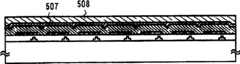
当获得图5(C)所示的状态时,把基底转移到用于第一汽相膜形成的处理腔中,在其中通过真空蒸发形成一个由包含属于周期表中第1族或第2族的元素的金属膜制成的阴极507。在本实施例中,以10:1的比例共同蒸发镁和银,由此形成由Mg-Ag制成的阴极507。When the state shown in FIG. 5(C) is obtained, the substrate is transferred to the processing chamber for the first vapor phase film formation, in which a film comprising a film belonging to Group 1 or Group 2 of the periodic table is formed by vacuum evaporation. The
再后,从用于第一汽相膜形成的处理腔110中取出形成有阴极507的基底,并通过转移机构105转移到用于第二汽相膜形成的处理腔111中。在后一个处理腔111中,在阴极507上形成一个主要成份为铝的电极(辅助电极)508.由此达到图5(D)的状态.Then, the substrate on which the
之后,在需要时通过真空蒸发或溅射提供诸如氮化硅膜的钝化膜。在设置钝化膜的情况下,可以给薄膜形成装置提前配置用于形成绝缘膜的处理腔,或者通过另一种装置一次取出基底并形成带有钝化膜的基底。After that, a passivation film such as a silicon nitride film is provided by vacuum evaporation or sputtering as necessary. In the case of providing a passivation film, a processing chamber for forming an insulating film may be provided in advance to the thin film forming device, or the substrate may be taken out at one time by another device and the substrate with the passivation film may be formed.
此外,利用如实施例3中所示的薄膜形成装置可以在基底暴露给空气之前最终封装EL元件。Furthermore, using the thin film forming apparatus as shown in Example 3, the EL element can be finally encapsulated before the substrate is exposed to the air.
顺便说一下,虽然本实施例举例说明了用本发明的薄膜形成装置制造有源矩阵型EL显示装置,但本发明的装置也可以用于简单矩阵型EL显示装置的制造。此外,还可以使用实施例2-5中的任何一种薄膜形成装置。Incidentally, although this embodiment exemplifies the manufacture of an active matrix type EL display device using the thin film forming apparatus of the present invention, the apparatus of the present invention can also be used for the manufacture of a simple matrix type EL display device. In addition, any of the thin film forming apparatuses in Examples 2-5 can also be used.
[实施例7][Example 7]
在本实施例中,参见图6(A)至6(E)对采用本发明的薄膜形成装置制造有源矩阵型EL显示装置的另一实例进行描述。顺便说一下,在本实施例中,将以实施例1中所述的装置为例。因此,关于在各个处理腔中执行的处理步骤的细节可以引用实施例1的描述。In this embodiment, another example of manufacturing an active matrix type EL display device using the thin film forming apparatus of the present invention will be described with reference to FIGS. 6(A) to 6(E). Incidentally, in this embodiment, the device described in Embodiment 1 will be taken as an example. Therefore, the description of Embodiment 1 can be referred to for the details of the processing steps performed in the respective processing chambers.
首先,如图6(A)所示,在玻璃基底601上形成以矩阵形状分布的象素602。虽然在本实施例中采用的是玻璃基底601,但可以用任何材料做基底。First, as shown in FIG. 6(A),
此外,每个象素602有一个TFT 603和一个象素电极(阴极)604,并且流到象素电极604的电流通过TFT 603控制.制造TFT 603的方法可以遵从任何一种已知的制造TFT的方法。当然,TFT 603可以是上栅极型TFT,也可以是下栅极型TFT。(图6(A))In addition, each
另外,可以用主要成份为铝的膜形成象素电极603。在本实施例中,从EL元件发出的光入射到基底601的对面(在图6(A)中向上看)。在这种情况下,象素电极用作反射电极。因此倾向于采用具有最高反射率的材料。Alternatively, the
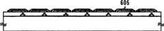
随后,把图6(A)中所示的基底放到载体102中,并把载体102置入图1所示薄膜形成装置的转移腔101。此外,通过转移机构105把基底转移到用于第一汽相膜形成的处理腔内,在该处理腔内通过真空蒸发形成由包含属于第1族或第2族元素的金属膜制成的阴极605。在本实施例中,形成由Mg-Ag制成的阴极605.顺便说一下,通过采用掩膜的真空蒸发选择性地形成与各个象素电极604对应的阴极605。(图6(B))Subsequently, the substrate shown in FIG. 6(A) is placed in the
随后,通过转移机构105把基底转移到用于施用溶液的处理腔108中,并通过旋转涂敷在其上涂敷包含EI材料的溶液,由此形成高分子EL层的预制件605。在本实施例中,采用在二氯甲烷中溶解聚乙烯咔唑的溶液。当然,也可以采用高分子EL材料和有机溶剂之间的任何其他适当的组合物.(图6(C))Subsequently, the substrate is transferred by the
另外,把所得的基底转移到用于烘烤的处理腔109中,在其中执行烘烤处理(热处理)以聚合EL材料。在本实施例中,整个基底通过加热器的加热阶段在50-150℃(110-120℃更好)下经受热处理。过剩的二氯甲烷由此挥发,形成高分子EL层(聚乙烯咔唑膜)607。(图6(D))In addition, the resulting substrate is transferred to the
当达到图6(D)所示的状态时,把基底转移到用于第二汽相膜形成的处理腔111中,在其中通过溅射形成一个由透明导电膜制成的阳极608。在本实施例中,采用在氧化铟中混有10-15%的氧化锌的混合物。由此达到图6(E)的状态。When the state shown in FIG. 6(D) is reached, the substrate is transferred to the
之后,在需要时通过真空蒸发或溅射提供诸如氮化硅膜的钝化膜。在设置钝化膜的情况下,可以给薄膜形成装置提前配置用于形成绝缘膜的处理腔,或者通过另一种装置一次取出基底并形成带有钝化膜的基底。After that, a passivation film such as a silicon nitride film is provided by vacuum evaporation or sputtering as necessary. In the case of providing a passivation film, a processing chamber for forming an insulating film may be provided in advance to the thin film forming device, or the substrate may be taken out at one time by another device and the substrate with the passivation film may be formed.
此外,利用如实施例3中所示的薄膜形成装置可以在基底暴露给空气之前最终封装EL元件。Furthermore, using the thin film forming apparatus as shown in Example 3, the EL element can be finally encapsulated before the substrate is exposed to the air.
顺便说一下,虽然本实施例举例说明了用本发明的薄膜形成装置制造有源矩阵型EL显示装置,但本发明的装置也可以用于简单矩阵型EL显示装置的制造。此外,还可以使用实施例2-5中的任何一种薄膜形成装置.Incidentally, although this embodiment exemplifies the manufacture of an active matrix type EL display device using the thin film forming apparatus of the present invention, the apparatus of the present invention can also be used for the manufacture of a simple matrix type EL display device. In addition, any of the thin film forming apparatuses in Examples 2-5 can also be used.
本发明产生的效果叙述如下。The effects produced by the present invention are described below.
负荷多腔系统或在线系统地集成利用旋转涂敷法形成用于形成高分子EL层的处理腔和其他用于预处理和形成电极的处理腔,由此无退化问题地制造采用高分子EL材料的EL元件。因此,可以极大地提高采用了高分子EL材料的EL显示装置的可靠性。Loading a multi-chamber system or in-line systematically integrating processing chambers for forming polymer EL layers and other processing chambers for pretreatment and electrode formation by spin coating, thereby manufacturing polymer EL materials without degradation problems EL elements. Therefore, the reliability of the EL display device using the polymer EL material can be greatly improved.
Claims (12)
Applications Claiming Priority (2)
| Application Number | Priority Date | Filing Date | Title |
|---|---|---|---|
| JP209221/99 | 1999-07-23 | ||
| JP20922199 | 1999-07-23 |
Related Parent Applications (1)
| Application Number | Title | Priority Date | Filing Date |
|---|---|---|---|
| CNB001217402ADivisionCN1188014C (en) | 1999-07-23 | 2000-07-24 | Method for manufacturing electroluminescent display device and device for forming thin film |
Publications (2)
| Publication Number | Publication Date |
|---|---|
| CN1691845A CN1691845A (en) | 2005-11-02 |
| CN100483787Ctrue CN100483787C (en) | 2009-04-29 |
Family
ID=16569365
Family Applications (2)
| Application Number | Title | Priority Date | Filing Date |
|---|---|---|---|
| CNB001217402AExpired - Fee RelatedCN1188014C (en) | 1999-07-23 | 2000-07-24 | Method for manufacturing electroluminescent display device and device for forming thin film |
| CNB200410102249XAExpired - Fee RelatedCN100483787C (en) | 1999-07-23 | 2000-07-24 | Method of fabricating an el display device, and apparatus for forming a thin film |
Family Applications Before (1)
| Application Number | Title | Priority Date | Filing Date |
|---|---|---|---|
| CNB001217402AExpired - Fee RelatedCN1188014C (en) | 1999-07-23 | 2000-07-24 | Method for manufacturing electroluminescent display device and device for forming thin film |
Country Status (5)
| Country | Link |
|---|---|
| US (2) | US6776880B1 (en) |
| EP (1) | EP1071117B1 (en) |
| KR (2) | KR100751512B1 (en) |
| CN (2) | CN1188014C (en) |
| TW (1) | TW504941B (en) |
Families Citing this family (107)
| Publication number | Priority date | Publication date | Assignee | Title |
|---|---|---|---|---|
| JPH08264802A (en)* | 1995-03-28 | 1996-10-11 | Semiconductor Energy Lab Co Ltd | Semiconductor manufacturing method, thin film transistor manufacturing method, and thin film transistor |
| JP4827294B2 (en)* | 1999-11-29 | 2011-11-30 | 株式会社半導体エネルギー研究所 | Film forming apparatus and method for manufacturing light emitting apparatus |
| TW490714B (en)* | 1999-12-27 | 2002-06-11 | Semiconductor Energy Lab | Film formation apparatus and method for forming a film |
| KR100816197B1 (en) | 2000-03-22 | 2008-03-21 | 이데미쓰 고산 가부시키가이샤 | Manufacturing apparatus of organic electroluminescent display and manufacturing method of organic electroluminescent display using same |
| TWI226205B (en)* | 2000-03-27 | 2005-01-01 | Semiconductor Energy Lab | Self-light emitting device and method of manufacturing the same |
| US20020011205A1 (en)* | 2000-05-02 | 2002-01-31 | Shunpei Yamazaki | Film-forming apparatus, method of cleaning the same, and method of manufacturing a light-emitting device |
| US7517551B2 (en) | 2000-05-12 | 2009-04-14 | Semiconductor Energy Laboratory Co., Ltd. | Method of manufacturing a light-emitting device |
| US6605826B2 (en) | 2000-08-18 | 2003-08-12 | Semiconductor Energy Laboratory Co., Ltd. | Light-emitting device and display device |
| US7462372B2 (en)* | 2000-09-08 | 2008-12-09 | Semiconductor Energy Laboratory Co., Ltd. | Light emitting device, method of manufacturing the same, and thin film forming apparatus |
| TW471142B (en)* | 2000-09-18 | 2002-01-01 | Ritdisplay Corp | Mass production packaging method |
| US6924594B2 (en)* | 2000-10-03 | 2005-08-02 | Semiconductor Energy Laboratory Co., Ltd. | Light emitting device |
| ES2270907T3 (en)* | 2001-01-26 | 2007-04-16 | Ipsen International Gmbh | DEVICE AND PROCEDURE FOR TRANSPORTING METAL WORK PARTS AND INSTALLATION FOR THERMAL TREATMENT OF THESE PARTS. |
| JP4906018B2 (en)* | 2001-03-12 | 2012-03-28 | 株式会社半導体エネルギー研究所 | Film forming method, light emitting device manufacturing method, and film forming apparatus |
| JP4078813B2 (en)* | 2001-06-12 | 2008-04-23 | ソニー株式会社 | Film forming apparatus and film forming method |
| JP3602847B2 (en)* | 2001-06-14 | 2004-12-15 | 三星ダイヤモンド工業株式会社 | Organic EL display manufacturing apparatus and organic EL display manufacturing method |
| TW548860B (en) | 2001-06-20 | 2003-08-21 | Semiconductor Energy Lab | Light emitting device and method of manufacturing the same |
| US7211828B2 (en) | 2001-06-20 | 2007-05-01 | Semiconductor Energy Laboratory Co., Ltd. | Light emitting device and electronic apparatus |
| JP4593019B2 (en)* | 2001-06-25 | 2010-12-08 | 株式会社半導体エネルギー研究所 | Method for manufacturing light emitting device |
| TW588403B (en)* | 2001-06-25 | 2004-05-21 | Tokyo Electron Ltd | Substrate treating device and substrate treating method |
| JP4865165B2 (en) | 2001-08-29 | 2012-02-01 | 株式会社半導体エネルギー研究所 | Method for manufacturing light emitting device |
| KR100430336B1 (en)* | 2001-11-16 | 2004-05-03 | 정광호 | Apparatus for manufacturing organic electro-luminescent light emitting devices for mass production |
| US6688365B2 (en)* | 2001-12-19 | 2004-02-10 | Eastman Kodak Company | Method for transferring of organic material from a donor to form a layer in an OLED device |
| JP4066661B2 (en)* | 2002-01-23 | 2008-03-26 | セイコーエプソン株式会社 | Organic EL device manufacturing apparatus and droplet discharge apparatus |
| TWI262034B (en)* | 2002-02-05 | 2006-09-11 | Semiconductor Energy Lab | Manufacturing system, manufacturing method, method of operating a manufacturing apparatus, and light emitting device |
| TWI285515B (en)* | 2002-02-22 | 2007-08-11 | Semiconductor Energy Lab | Light-emitting device and method of manufacturing the same, and method of operating manufacturing apparatus |
| SG113448A1 (en) | 2002-02-25 | 2005-08-29 | Semiconductor Energy Lab | Fabrication system and a fabrication method of a light emitting device |
| US7309269B2 (en) | 2002-04-15 | 2007-12-18 | Semiconductor Energy Laboratory Co., Ltd. | Method of fabricating light-emitting device and apparatus for manufacturing light-emitting device |
| US7474045B2 (en)* | 2002-05-17 | 2009-01-06 | Semiconductor Energy Laboratory Co., Ltd. | Display device having TFT with radiation-absorbing film |
| US20030221620A1 (en)* | 2002-06-03 | 2003-12-04 | Semiconductor Energy Laboratory Co., Ltd. | Vapor deposition device |
| US7230271B2 (en) | 2002-06-11 | 2007-06-12 | Semiconductor Energy Laboratory Co., Ltd. | Light emitting device comprising film having hygroscopic property and transparency and manufacturing method thereof |
| TWI276366B (en) | 2002-07-09 | 2007-03-11 | Semiconductor Energy Lab | Production apparatus and method of producing a light-emitting device by using the same apparatus |
| US7988398B2 (en) | 2002-07-22 | 2011-08-02 | Brooks Automation, Inc. | Linear substrate transport apparatus |
| US7959395B2 (en) | 2002-07-22 | 2011-06-14 | Brooks Automation, Inc. | Substrate processing apparatus |
| US20040040504A1 (en)* | 2002-08-01 | 2004-03-04 | Semiconductor Energy Laboratory Co., Ltd. | Manufacturing apparatus |
| JP2004069395A (en)* | 2002-08-02 | 2004-03-04 | Nec Corp | Microchip, method for manufacturing the same, and constituent detection method |
| US20040123804A1 (en) | 2002-09-20 | 2004-07-01 | Semiconductor Energy Laboratory Co., Ltd. | Fabrication system and manufacturing method of light emitting device |
| JP4549866B2 (en) | 2003-02-05 | 2010-09-22 | 株式会社半導体エネルギー研究所 | Manufacturing method of display device |
| WO2004070819A1 (en)* | 2003-02-05 | 2004-08-19 | Semiconductor Energy Laboratory Co., Ltd. | Method for manufacturing display |
| JP4526951B2 (en)* | 2003-02-06 | 2010-08-18 | 株式会社半導体エネルギー研究所 | Method for manufacturing display device |
| KR101186919B1 (en)* | 2003-02-06 | 2012-10-02 | 가부시키가이샤 한도오따이 에네루기 켄큐쇼 | Method for manufacturing display device |
| KR101113773B1 (en)* | 2003-02-06 | 2012-03-13 | 가부시키가이샤 한도오따이 에네루기 켄큐쇼 | Semiconductor producing apparatus |
| JP4748990B2 (en)* | 2003-02-06 | 2011-08-17 | 株式会社半導体エネルギー研究所 | Manufacturing method of semiconductor device |
| US7202504B2 (en) | 2004-05-20 | 2007-04-10 | Semiconductor Energy Laboratory Co., Ltd. | Light-emitting element and display device |
| US20050257738A1 (en)* | 2004-05-21 | 2005-11-24 | Semiconductor Energy Laboratory Co., Ltd. | Manufacturing apparatus of semiconductor device and pattern-forming method |
| US8986780B2 (en) | 2004-11-19 | 2015-03-24 | Massachusetts Institute Of Technology | Method and apparatus for depositing LED organic film |
| US8128753B2 (en) | 2004-11-19 | 2012-03-06 | Massachusetts Institute Of Technology | Method and apparatus for depositing LED organic film |
| US9099506B2 (en)* | 2005-03-30 | 2015-08-04 | Brooks Automation, Inc. | Transfer chamber between workstations |
| CN101950732B (en)* | 2005-11-09 | 2014-12-10 | 株式会社半导体能源研究所 | Semiconductor device and manufacturing method thereof |
| KR101353567B1 (en) | 2006-04-28 | 2014-01-22 | 가부시키가이샤 한도오따이 에네루기 켄큐쇼 | Electrode cover and evaporation device |
| EP2155494A4 (en) | 2007-06-14 | 2010-08-11 | Massachusetts Inst Technology | METHOD AND APPARATUS FOR REGULATING A FILM DEPOSITION |
| US8556389B2 (en) | 2011-02-04 | 2013-10-15 | Kateeva, Inc. | Low-profile MEMS thermal printhead die having backside electrical connections |
| JP5208591B2 (en) | 2007-06-28 | 2013-06-12 | 株式会社半導体エネルギー研究所 | Light emitting device and lighting device |
| US20090218219A1 (en)* | 2008-02-29 | 2009-09-03 | Semiconductor Energy Laboratory Co., Ltd. | Manufacturing Apparatus |
| JP5416987B2 (en) | 2008-02-29 | 2014-02-12 | 株式会社半導体エネルギー研究所 | Film forming method and light emitting device manufacturing method |
| JP5238544B2 (en)* | 2008-03-07 | 2013-07-17 | 株式会社半導体エネルギー研究所 | Film forming method and light emitting device manufacturing method |
| JP5079722B2 (en) | 2008-03-07 | 2012-11-21 | 株式会社半導体エネルギー研究所 | Method for manufacturing light emitting device |
| US8409672B2 (en)* | 2008-04-24 | 2013-04-02 | Semiconductor Energy Laboratory Co., Ltd. | Method of manufacturing evaporation donor substrate and method of manufacturing light-emitting device |
| US8242487B2 (en)* | 2008-05-16 | 2012-08-14 | E I Du Pont De Nemours And Company | Anode for an organic electronic device |
| KR101629637B1 (en)* | 2008-05-29 | 2016-06-13 | 가부시키가이샤 한도오따이 에네루기 켄큐쇼 | Deposition method and method of manufacturing light-emitting device |
| US8383202B2 (en) | 2008-06-13 | 2013-02-26 | Kateeva, Inc. | Method and apparatus for load-locked printing |
| US12064979B2 (en) | 2008-06-13 | 2024-08-20 | Kateeva, Inc. | Low-particle gas enclosure systems and methods |
| US10442226B2 (en) | 2008-06-13 | 2019-10-15 | Kateeva, Inc. | Gas enclosure assembly and system |
| US9048344B2 (en) | 2008-06-13 | 2015-06-02 | Kateeva, Inc. | Gas enclosure assembly and system |
| US10434804B2 (en) | 2008-06-13 | 2019-10-08 | Kateeva, Inc. | Low particle gas enclosure systems and methods |
| US9604245B2 (en) | 2008-06-13 | 2017-03-28 | Kateeva, Inc. | Gas enclosure systems and methods utilizing an auxiliary enclosure |
| US11975546B2 (en) | 2008-06-13 | 2024-05-07 | Kateeva, Inc. | Gas enclosure assembly and system |
| US12018857B2 (en) | 2008-06-13 | 2024-06-25 | Kateeva, Inc. | Gas enclosure assembly and system |
| US8899171B2 (en) | 2008-06-13 | 2014-12-02 | Kateeva, Inc. | Gas enclosure assembly and system |
| US20100021273A1 (en)* | 2008-07-28 | 2010-01-28 | Applied Materials, Inc. | Concrete vacuum chamber |
| JP2010055864A (en)* | 2008-08-27 | 2010-03-11 | Sumitomo Chemical Co Ltd | Organic electroluminescent device and its manufacturing method |
| JP5173699B2 (en)* | 2008-09-25 | 2013-04-03 | 株式会社日立ハイテクノロジーズ | Organic EL device manufacturing equipment |
| WO2010065505A2 (en)* | 2008-12-01 | 2010-06-10 | E. I. Du Pont De Nemours And Company | Anode for an organic electronic device |
| TW201336140A (en)* | 2008-12-15 | 2013-09-01 | Hitachi High Tech Corp | Organic el device manufacturing apparatus, film forming apparatus |
| US8461758B2 (en)* | 2008-12-19 | 2013-06-11 | E I Du Pont De Nemours And Company | Buffer bilayers for electronic devices |
| US20100188457A1 (en)* | 2009-01-05 | 2010-07-29 | Madigan Connor F | Method and apparatus for controlling the temperature of an electrically-heated discharge nozzle |
| CN102356697B (en) | 2009-03-18 | 2014-05-28 | 株式会社半导体能源研究所 | Lighting device |
| EP2230703A3 (en)* | 2009-03-18 | 2012-05-02 | Semiconductor Energy Laboratory Co., Ltd. | Manufacturing apparatus and manufacturing method of lighting device |
| US8602706B2 (en) | 2009-08-17 | 2013-12-10 | Brooks Automation, Inc. | Substrate processing apparatus |
| CN102054910B (en)* | 2010-11-19 | 2013-07-31 | 理想能源设备(上海)有限公司 | LED chip process integration system and treating method thereof |
| US9722212B2 (en) | 2011-02-14 | 2017-08-01 | Semiconductor Energy Laboratory Co., Ltd. | Lighting device, light-emitting device, and manufacturing method and manufacturing apparatus thereof |
| CN106299116B (en) | 2011-08-09 | 2019-07-12 | 科迪华公司 | Printing device and method downwards |
| US9120344B2 (en) | 2011-08-09 | 2015-09-01 | Kateeva, Inc. | Apparatus and method for control of print gap |
| US9578718B2 (en) | 2012-05-04 | 2017-02-21 | Semiconductor Energy Laboratory Co., Ltd. | Method for manufacturing light-emitting element and deposition apparatus |
| KR101990555B1 (en)* | 2012-12-24 | 2019-06-19 | 삼성디스플레이 주식회사 | Thin film encapsulation manufacturing device and manufacturing method of thin film encapsulation |
| US10468279B2 (en)* | 2013-12-26 | 2019-11-05 | Kateeva, Inc. | Apparatus and techniques for thermal treatment of electronic devices |
| US9343678B2 (en) | 2014-01-21 | 2016-05-17 | Kateeva, Inc. | Apparatus and techniques for electronic device encapsulation |
| KR102307190B1 (en) | 2014-01-21 | 2021-09-30 | 카티바, 인크. | Apparatus and techniques for electronic device encapsulation |
| CN103956437B (en)* | 2014-01-23 | 2016-01-06 | 深圳市华星光电技术有限公司 | A kind of packaging system for the manufacture of OLED display screen and method |
| EP3882961B1 (en) | 2014-04-30 | 2023-07-26 | Kateeva, Inc. | Gas cushion apparatus and techniques for substrate coating |
| CN103996801B (en)* | 2014-06-12 | 2017-05-31 | 深圳市华星光电技术有限公司 | Substrate pre-treating method and device |
| WO2016086192A1 (en) | 2014-11-26 | 2016-06-02 | Kateeva, Inc. | Environmentally controlled coating systems |
| DE102015101875B4 (en)* | 2015-02-10 | 2018-05-24 | VON ARDENNE Asset GmbH & Co. KG | Processing arrangement and method for processing a substrate |
| FR3042728B1 (en)* | 2015-10-22 | 2017-12-08 | Les Laboratoires Osteal Medical | SEALED POLYMERIZATION ENCLOSURE |
| EP3377234A4 (en) | 2015-11-16 | 2019-08-07 | Kateeva, Inc. | SYSTEMS AND METHODS FOR THERMALLY PROCESSING A SUBSTRATE |
| US10763139B2 (en)* | 2017-05-23 | 2020-09-01 | Tokyo Electron Limited | Vacuum transfer module and substrate processing apparatus |
| JP6605657B1 (en)* | 2018-05-24 | 2019-11-13 | キヤノントッキ株式会社 | Film forming apparatus, film forming method, and electronic device manufacturing method |
| KR102697922B1 (en)* | 2019-01-09 | 2024-08-22 | 삼성전자주식회사 | Apparatus for atomic layer deposition and method for forming thin film using the same |
| US10998209B2 (en) | 2019-05-31 | 2021-05-04 | Applied Materials, Inc. | Substrate processing platforms including multiple processing chambers |
| US12080571B2 (en) | 2020-07-08 | 2024-09-03 | Applied Materials, Inc. | Substrate processing module and method of moving a workpiece |
| US11749542B2 (en) | 2020-07-27 | 2023-09-05 | Applied Materials, Inc. | Apparatus, system, and method for non-contact temperature monitoring of substrate supports |
| US11817331B2 (en) | 2020-07-27 | 2023-11-14 | Applied Materials, Inc. | Substrate holder replacement with protective disk during pasting process |
| US11600507B2 (en) | 2020-09-09 | 2023-03-07 | Applied Materials, Inc. | Pedestal assembly for a substrate processing chamber |
| US11610799B2 (en) | 2020-09-18 | 2023-03-21 | Applied Materials, Inc. | Electrostatic chuck having a heating and chucking capabilities |
| US12195314B2 (en) | 2021-02-02 | 2025-01-14 | Applied Materials, Inc. | Cathode exchange mechanism to improve preventative maintenance time for cluster system |
| US11674227B2 (en) | 2021-02-03 | 2023-06-13 | Applied Materials, Inc. | Symmetric pump down mini-volume with laminar flow cavity gas injection for high and low pressure |
| US11752518B2 (en) | 2021-06-03 | 2023-09-12 | Sst Systems, Inc. | Robot-centered coating system with multiple curing workstations |
| US12002668B2 (en) | 2021-06-25 | 2024-06-04 | Applied Materials, Inc. | Thermal management hardware for uniform temperature control for enhanced bake-out for cluster tool |
Family Cites Families (28)
| Publication number | Priority date | Publication date | Assignee | Title |
|---|---|---|---|---|
| JPS60121616A (en) | 1983-12-06 | 1985-06-29 | セイコーエプソン株式会社 | Method of forming transparent conductive film |
| US4951601A (en) | 1986-12-19 | 1990-08-28 | Applied Materials, Inc. | Multi-chamber integrated process system |
| US4885211A (en) | 1987-02-11 | 1989-12-05 | Eastman Kodak Company | Electroluminescent device with improved cathode |
| JPS6472159A (en)* | 1987-09-11 | 1989-03-17 | Fuji Photo Film Co Ltd | Projecting and printing device |
| US5186718A (en)* | 1989-05-19 | 1993-02-16 | Applied Materials, Inc. | Staged-vacuum wafer processing system and method |
| EP0408216A3 (en) | 1989-07-11 | 1991-09-18 | Hitachi, Ltd. | Method for processing wafers and producing semiconductor devices and apparatus for producing the same |
| US5067218A (en)* | 1990-05-21 | 1991-11-26 | Motorola, Inc. | Vacuum wafer transport and processing system and method using a plurality of wafer transport arms |
| US5404894A (en)* | 1992-05-20 | 1995-04-11 | Tokyo Electron Kabushiki Kaisha | Conveyor apparatus |
| DE69304038T2 (en)* | 1993-01-28 | 1996-12-19 | Applied Materials Inc | Device for a vacuum process with improved throughput |
| JP2770299B2 (en)* | 1993-10-26 | 1998-06-25 | 富士ゼロックス株式会社 | Thin-film EL element, method of manufacturing the same, and sputtering target used therefor |
| TW295677B (en)* | 1994-08-19 | 1997-01-11 | Tokyo Electron Co Ltd | |
| US5550066A (en) | 1994-12-14 | 1996-08-27 | Eastman Kodak Company | Method of fabricating a TFT-EL pixel |
| JP3644036B2 (en)* | 1995-02-15 | 2005-04-27 | 株式会社日立製作所 | Semiconductor device manufacturing method and semiconductor manufacturing apparatus |
| EP0732731A3 (en)* | 1995-03-13 | 1997-10-08 | Applied Materials Inc | Treatment of a layer of titanium nitride to improve resistance to high temperatures |
| WO1997046054A1 (en) | 1996-05-29 | 1997-12-04 | Idemitsu Kosan Co., Ltd. | Organic el device |
| JP3036436B2 (en)* | 1996-06-19 | 2000-04-24 | セイコーエプソン株式会社 | Method of manufacturing active matrix type organic EL display |
| US5817366A (en) | 1996-07-29 | 1998-10-06 | Tdk Corporation | Method for manufacturing organic electroluminescent element and apparatus therefor |
| JP3899566B2 (en) | 1996-11-25 | 2007-03-28 | セイコーエプソン株式会社 | Manufacturing method of organic EL display device |
| JPH10214682A (en)* | 1997-01-30 | 1998-08-11 | Mitsubishi Chem Corp | Manufacturing apparatus and manufacturing method for organic electroluminescent element |
| US6049167A (en) | 1997-02-17 | 2000-04-11 | Tdk Corporation | Organic electroluminescent display device, and method and system for making the same |
| JPH10241858A (en)* | 1997-02-25 | 1998-09-11 | Tdk Corp | Manufacture of organic electroluminescent display device and device therefor |
| JP3288242B2 (en)* | 1997-02-17 | 2002-06-04 | ティーディーケイ株式会社 | Organic electroluminescence display device and method of manufacturing the same |
| JP2845856B2 (en)* | 1997-03-10 | 1999-01-13 | 出光興産株式会社 | Method for manufacturing organic electroluminescence device |
| JP3782245B2 (en) | 1998-10-28 | 2006-06-07 | Tdk株式会社 | Manufacturing apparatus and manufacturing method of organic EL display device |
| US6328815B1 (en)* | 1999-02-19 | 2001-12-11 | Taiwan Semiconductor Manufacturing Company | Multiple chamber vacuum processing system configuration for improving the stability of mark shielding process |
| US6440261B1 (en)* | 1999-05-25 | 2002-08-27 | Applied Materials, Inc. | Dual buffer chamber cluster tool for semiconductor wafer processing |
| JP4472056B2 (en) | 1999-07-23 | 2010-06-02 | 株式会社半導体エネルギー研究所 | Electroluminescence display device and manufacturing method thereof |
| JP4140674B2 (en)* | 1999-09-27 | 2008-08-27 | 東京エレクトロン株式会社 | Method and apparatus for observing porous amorphous film |
- 2000
- 2000-07-05TWTW089113293Apatent/TW504941B/ennot_activeIP Right Cessation
- 2000-07-14EPEP00115329.5Apatent/EP1071117B1/ennot_activeExpired - Lifetime
- 2000-07-19USUS09/619,486patent/US6776880B1/ennot_activeExpired - Lifetime
- 2000-07-21KRKR1020000041825Apatent/KR100751512B1/ennot_activeExpired - Fee Related
- 2000-07-24CNCNB001217402Apatent/CN1188014C/ennot_activeExpired - Fee Related
- 2000-07-24CNCNB200410102249XApatent/CN100483787C/ennot_activeExpired - Fee Related
- 2004
- 2004-08-02USUS10/902,792patent/US7258768B2/ennot_activeExpired - Lifetime
- 2005
- 2005-07-19KRKR1020050065169Apatent/KR100751513B1/ennot_activeExpired - Fee Related
Also Published As
| Publication number | Publication date |
|---|---|
| CN1691845A (en) | 2005-11-02 |
| US7258768B2 (en) | 2007-08-21 |
| TW504941B (en) | 2002-10-01 |
| KR20050080457A (en) | 2005-08-12 |
| KR20010015386A (en) | 2001-02-26 |
| KR100751513B1 (en) | 2007-08-23 |
| EP1071117A2 (en) | 2001-01-24 |
| US6776880B1 (en) | 2004-08-17 |
| KR100751512B1 (en) | 2007-08-23 |
| EP1071117A3 (en) | 2006-04-19 |
| CN1283952A (en) | 2001-02-14 |
| CN1188014C (en) | 2005-02-02 |
| EP1071117B1 (en) | 2013-10-09 |
| US20050005850A1 (en) | 2005-01-13 |
Similar Documents
| Publication | Publication Date | Title |
|---|---|---|
| CN100483787C (en) | Method of fabricating an el display device, and apparatus for forming a thin film | |
| JP4425438B2 (en) | Method for manufacturing EL display device | |
| KR101003404B1 (en) | Manufacturing system and light emitting device manufacturing method | |
| JP5072184B2 (en) | Deposition method | |
| US8206562B2 (en) | Apparatus and method for the application of a material layer to display devices | |
| CN100565784C (en) | Manufacturing Equipment | |
| US8123862B2 (en) | Deposition apparatus and manufacturing apparatus | |
| KR101004060B1 (en) | Manufacturing system, light emitting device, and method for producing an organic compound containing layer | |
| EP0859539A2 (en) | Organic electroluminescent display device, and method and system for making the same | |
| TW201220921A (en) | Light emitting device, electronic equipment and apparatus for manufacturing the same | |
| TW200306131A (en) | Manufacturing system, manufacturing method, method of operating a manufacturing apparatus, and light emitting device | |
| JPH10214682A (en) | Manufacturing apparatus and manufacturing method for organic electroluminescent element | |
| JPH10241858A (en) | Manufacture of organic electroluminescent display device and device therefor | |
| JP4439827B2 (en) | Manufacturing apparatus and light emitting device manufacturing method | |
| CN103855316B (en) | A kind of organic electroluminescence device and preparation method thereof | |
| JP2004006311A (en) | Method and apparatus for manufacturing light-emitting device | |
| JP4468328B2 (en) | Method for manufacturing EL display device | |
| WO1999003122A1 (en) | Anhydrous method of packaging organic light emitting displays |
Legal Events
| Date | Code | Title | Description |
|---|---|---|---|
| C06 | Publication | ||
| PB01 | Publication | ||
| C10 | Entry into substantive examination | ||
| SE01 | Entry into force of request for substantive examination | ||
| C14 | Grant of patent or utility model | ||
| GR01 | Patent grant | ||
| CF01 | Termination of patent right due to non-payment of annual fee | ||
| CF01 | Termination of patent right due to non-payment of annual fee | Granted publication date:20090429 Termination date:20190724 |