CN100483208C - Light-guiding board and back-light module using same - Google Patents
Light-guiding board and back-light module using sameDownload PDFInfo
- Publication number
- CN100483208C CN100483208CCNB200510035878XACN200510035878ACN100483208CCN 100483208 CCN100483208 CCN 100483208CCN B200510035878X ACNB200510035878X ACN B200510035878XACN 200510035878 ACN200510035878 ACN 200510035878ACN 100483208 CCN100483208 CCN 100483208C
- Authority
- CN
- China
- Prior art keywords
- light
- dots
- guide plate
- backlight module
- light guide
- Prior art date
- Legal status (The legal status is an assumption and is not a legal conclusion. Google has not performed a legal analysis and makes no representation as to the accuracy of the status listed.)
- Expired - Fee Related
Links
Images

Landscapes
- Planar Illumination Modules (AREA)
- Light Guides In General And Applications Therefor (AREA)
Abstract
Translated fromChinese
Description
Translated fromChinese【技术领域】【Technical field】
本发明涉及一种导光板和采用该导光板的背光模组,尤其涉及一种具网点分布的导光板和采用该导光板的背光模组。The invention relates to a light guide plate and a backlight module using the light guide plate, in particular to a light guide plate with dot distribution and a backlight module using the light guide plate.
【背景技术】【Background technique】
由于液晶显示器面板的液晶本身不具发光特性,因而,为达到显示效果,需给液晶显示器面板提供一面光源装置,如背光模组,其作用在于向液晶显示器面板供应亮度充分并且分布均匀的面光源。Since the liquid crystal itself of the liquid crystal display panel does not have light-emitting characteristics, in order to achieve the display effect, it is necessary to provide the liquid crystal display panel with a surface light source device, such as a backlight module, whose function is to supply a surface light source with sufficient brightness and uniform distribution to the liquid crystal display panel.
现有技术的背光模组主要由光源、导光板、反射板、扩散板与棱镜板组成。该光源可设置于导光板一侧或两相对侧并将光线发射至该导光板。该导光板的作用在于引导光线传输方向,使光线由导光板的出光面均匀出射,反射板相对该导光板的底面设置,以将由导光板底面出射的光线再次反射入该导光板内,提高光线的利用率。扩散板与棱镜板相对导光板的出光面依次设置,以使由导光板出射的光线分布更加均匀,进而提高液晶显示器面板的亮度与均匀性。The backlight module in the prior art is mainly composed of a light source, a light guide plate, a reflection plate, a diffuser plate and a prism plate. The light source can be arranged on one side or two opposite sides of the light guide plate and emit light to the light guide plate. The function of the light guide plate is to guide the direction of light transmission, so that the light is uniformly emitted from the light-emitting surface of the light guide plate. utilization rate. The diffuser plate and the prism plate are sequentially arranged relative to the light-emitting surface of the light guide plate to make the distribution of light emitted from the light guide plate more uniform, thereby improving the brightness and uniformity of the liquid crystal display panel.
依导光板的形状,其可分为平板形导光板与楔形导光板。为增加导光板的出光效率与均匀性,通常在导光板的一面设置V形槽或配置网点,该V形槽或网点于导光板上分布的距离与大小可有不同设计。当光线传输至V形槽或网点时,光线将发生反射与散射,并向各个不同方向传输,最终由导光板的出光面射出。利用各种疏密、大小不同的V形槽或网点,可使导光板发光均匀。According to the shape of the light guide plate, it can be divided into a flat light guide plate and a wedge-shaped light guide plate. In order to increase the light extraction efficiency and uniformity of the light guide plate, V-shaped grooves or dots are usually arranged on one side of the light guide plate. The distance and size of the V-shaped grooves or dots distributed on the light guide plate can be designed in different ways. When the light is transmitted to the V-shaped groove or dot, the light will be reflected and scattered, and transmitted in different directions, and finally emitted from the light-emitting surface of the light guide plate. V-shaped grooves or dots of various densities and sizes can be used to make the light guide plate emit light evenly.
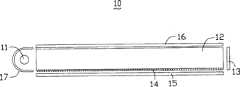
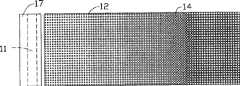
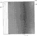
请一并参阅图1和图2,现有技术揭示一背光模组10,该背光模组10包括一具有入光面与出光面的导光板12、一设置于该导光板12入光面侧的光源11、一设置于该导光板12端面的反射片13、相对该导光板12出光面设置的扩散板16与相对该导光板12底面设置的反射板15。其中,为有效利用光源11所发出的光线,其也设置一反射灯罩17于该光源11处。另外,为破坏光线在导光板12内部传输的全反射条件,该导光板12底面又设置多个呈行列状排布的圆形网点14。该网点14沿与光源11轴向平行的方向排布成多列,并且每一列中网点14的大小相同。该网点14沿与光源11轴向垂直的方向排布成多行,并且每一行中网点14的大小不同,其中,靠近光源11的网点14的直径最小,随着与光源11距离的增大,该网点3也逐渐变大。Please refer to FIG. 1 and FIG. 2 together. The prior art discloses a
该导光板12的网点14沿与光源11轴向平行的方向排布成多列,其相邻的多个网点14之间围成的间隙(未标示)的面积较大,即单位面积的网点分布密度较低,此将导致出光均匀度较低。而且,该间隙在每一列上均为线形平齐排列,应用于显示面板,每一列线形平齐排列的间隙将可能产生一条亮线,直接降低显示品质。The
另外,该网点14在该导光板12底面的分布,在一定程度上可以提高导光板1整个出光面的出光均匀度。然而,由于该导光板12邻近光源11的二角落处通常属于灯管的电极区域,出光亮度极低。因而难以实现整个导光板出光亮度的完全均匀、一致。In addition, the distribution of the
有鉴于此,提供一种通过改进网点设计以提高整个导光板出光亮度均匀性的导光板和采用该导光板的背光模组实为必要。In view of this, it is necessary to provide a light guide plate and a backlight module using the light guide plate to improve the uniformity of light output brightness of the entire light guide plate by improving the dot design.
【发明内容】【Content of invention】
下面将以若干实施例说明一种改进网点设计以提高整个导光板出光亮度均匀性的导光板,以及一种采用该导光板的背光模组。A light guide plate with improved dot design to improve the uniformity of light output brightness of the entire light guide plate and a backlight module using the light guide plate will be described below with several embodiments.
为实现上述内容,提供一种导光板,其包括一透光板,该透光板包括一入光面、一与该入光面相连的出光面、一与出光面相对的底面;以及多个形成于该透光板底面的网点,该多个网点为正六边形,且该多个网点于该底面呈矩阵分布。In order to achieve the above, a light guide plate is provided, which includes a light-transmitting plate, the light-transmitting plate includes a light incident surface, a light exit surface connected to the light incident surface, a bottom surface opposite to the light exit surface; and a plurality of The network dots formed on the bottom surface of the light-transmitting plate are regular hexagonal, and the multiple network dots are distributed in matrix on the bottom surface.
以及,提供一种背光模组,其包括:一导光板和一光源,该导光板包括:一透光板,该透光板包括一与该光源靠近的入光面、一与该入光面相连的出光面、一与出光面相对的底面,以及多个形成于该透光板底面的网点,该多个网点为正六边形,沿与入光面平行的方向,该多个网点排布成多列,且相邻的奇数列与偶数列网点分别错开一定间距而呈交错式分布。And, provide a backlight module, which includes: a light guide plate and a light source, the light guide plate includes: a light-transmitting plate, the light-transmitting plate includes a light incident surface close to the light source, a light incident surface A connected light-emitting surface, a bottom surface opposite to the light-emitting surface, and a plurality of dots formed on the bottom surface of the light-transmitting plate, the plurality of dots are regular hexagons, and the plurality of dots are arranged along a direction parallel to the light-incident surface into multiple columns, and the adjacent odd-numbered and even-numbered columns are staggered by a certain distance and distributed in a staggered manner.
与现有技术相比较,本实施例的导光板具有如下优点:该导光板的每个网点呈正六边形,因此相邻多个网点之间围成的间隙面积较小,即单位面积的网点排列较圆形更为紧密,从而对光的散射效果较好,因此出光均匀度较高。进一步的,本发明只有单入光面的导光板,网点离该入光面越远分布越密,单个网点面积越大,对光线的散射能力较强,恰可弥补导光板远离入光面的一端出光强度较弱的缺陷,进一步实现该导光板整体出光的均匀度;本发明具有两入光面的导光板在平行于入光面的中部条形区域内的网点分布较密,单个网点的面积较大,对光线的散射能力较强,恰可弥补导光板远离入光面的中间条形区域出光强度较弱的缺陷,进一步实现该导光板整体出光的均匀度。更进一步的,在该底面的四角落处,沿入光面轴向平行方向,越靠近角落单个网点面积越大、分布越密,可解决由于灯管的电极影响而使导光板的四角落处出光亮度较低的问题,以进一步提高该导光板整体出光的均匀度。Compared with the prior art, the light guide plate of this embodiment has the following advantages: each dot of the light guide plate is in the shape of a regular hexagon, so the gap area surrounded by adjacent dots is small, that is, the dots per unit area The arrangement is tighter than that of a circle, so that the light scattering effect is better, so the light uniformity is higher. Further, the present invention only has a light guide plate with a single light incident surface, the farther the dots are from the light incident surface, the denser the distribution, the larger the area of a single dot, and the stronger the ability to scatter light, which can just make up for the fact that the light guide plate is far away from the light incident surface. The defect of weak light output intensity at one end further realizes the uniformity of the light output of the light guide plate as a whole; the light guide plate with two light incident surfaces of the present invention has relatively dense network dot distribution in the middle strip area parallel to the light incident surface, and the single network point The large area and strong ability to scatter light can just make up for the defect of weak light output intensity in the middle strip area of the light guide plate away from the light incident surface, and further realize the uniformity of the overall light output of the light guide plate. Further, at the four corners of the bottom surface, along the direction parallel to the axial direction of the light incident surface, the closer to the corner, the larger the area of a single dot and the denser the distribution, which can solve the problem of the four corners of the light guide plate due to the influence of the electrodes of the lamp tube. The problem of low light output brightness is to further improve the uniformity of the light output of the light guide plate.
【附图说明】【Description of drawings】
图1是现有技术的背光模组的侧视图。FIG. 1 is a side view of a prior art backlight module.
图2是图1背光模组的网点于导光板底面的分布图。FIG. 2 is a distribution diagram of dots of the backlight module in FIG. 1 on the bottom surface of the light guide plate.
图3是本发明第一实施例的背光模组的侧视图。FIG. 3 is a side view of the backlight module according to the first embodiment of the present invention.
图4是图3背光模组的导光板网点分布示意图。FIG. 4 is a schematic diagram of dot distribution of the light guide plate of the backlight module in FIG. 3 .
图5是图4的局部V的放大示意图。FIG. 5 is an enlarged schematic view of a part V in FIG. 4 .
图6是本发明第二实施例的背光模组的侧视图。FIG. 6 is a side view of a backlight module according to a second embodiment of the present invention.
图7是图6背光模组的导光板网点分布示意图。FIG. 7 is a schematic diagram of dot distribution of the light guide plate of the backlight module in FIG. 6 .
【具体实施方式】【Detailed ways】
下面将结合附图和多个实施例对本发明的导光板和采用该导光板的背光模组作进一步的详细说明。The light guide plate and the backlight module using the light guide plate of the present invention will be further described in detail below with reference to the drawings and multiple embodiments.
请参阅图3,本发明第一实施例提供一种背光模组20,该背光模组20包括:一导光板(未标示)和一冷阴极灯管21,该导光板包括一透光板22和多个网点24。该透光板22包括一与该冷阴极灯管21靠近的入光面222、一与该入光面222相连的出光面224、一与出光面224相对的底面226。该多个网点24形成于该透光板22的底面226。Please refer to FIG. 3, the first embodiment of the present invention provides a backlight module 20, the backlight module 20 includes: a light guide plate (not marked) and a
请参阅图4,为提高该导光板的出光亮度与均匀性,该多个网点24整体上分布如下:沿与冷阴极灯管21轴向平行的方向,该多个网点24排布成多列;沿与冷阴极灯管21轴向垂直的方向,该多个网点24排布成多行。相邻的奇数列与偶数列网点分别错开一定间距而呈交错式分布。每一行中该多个网点24的大小不同,而且,靠近冷阴极灯管21的网点24的直径最小,随着与冷阴极灯管21距离的增大,该网点24的面积也逐渐变大。Please refer to Fig. 4, in order to improve the brightness and uniformity of the light output of the light guide plate, the plurality of
进一步的,为解决由于冷阴极灯管21的电极影响而使透光板22的四角落处出光亮度较低的问题,以提高该透光板22整体出光的均匀度,在透光板22的四个角落处,沿入光面轴向平行方向,越靠近角落,单个网点24的面积越大、分布越密。本实施中,除透光板22四角落外,每一列的网点大小相同。Further, in order to solve the problem that the brightness of the four corners of the light-transmitting
请参阅图5,本实施例的网点24包括一般的油墨网点或含有散射剂的油墨网点,其可以通过油墨印刷的方式形成于该透光板22的底面226。本实施例的网点24采用蜂巢状的正六边形设计。该多个网点24呈行列状分布,沿与冷阴极灯管21轴向垂直的方向,相邻奇数列与偶数列的相邻网点24中心的间距Xpitch的取值范围为:0.7746毫米<Xpitch<3.873毫米;沿与冷阴极灯管21轴向平行的方向,同一列相邻网点24中心的间距的Ypitch的取值范围为:0.5477毫米<Ypitch<2.739毫米。该网点24的六边形边长L的范围为0.123~4.81毫米,该网点24的面积范围为0.0398~60.075平方毫米。该网点24的厚度范围为5~20微米。Please refer to FIG. 5 , the
本实施例的网点24采用具有较佳光学能量利用率的正六边形设计,相邻多个网点24之间围成的间隙面积较小,即单位面积的网点排列较圆形为紧密,从而对光的散射效果较好,因此出光均匀度较高,而且,该设计可有效提供各个最佳化的角度视效,降低光学牛顿环现象。The
请再参阅图3,为进一步提高该导光板的出光亮度均匀性和光利用率,本实施例背光模组20进一步包括:依次设置于该透光板22的出光面224上方的一下扩散片25、一集光片26和一上扩散片27;一设置于该透光板22的底面226的反射片28;以及一靠近并围住该光源21的反光罩29。Please refer to FIG. 3 again. In order to further improve the uniformity of light output brightness and light utilization rate of the light guide plate, the backlight module 20 of this embodiment further includes: a diffusion sheet 25 sequentially arranged above the light output surface 224 of the light-transmitting
请参阅图6,本发明第二实施例提供一种背光模组30,该背光模组30包括:一导光板(未标示)和多个冷阴极灯管31、31′,该导光板包括:一透光板32和多个网点34。该透光板32包括两相对的入光面322、322′、一与该两入光面322、322′相连的出光面324、一与出光面324相对的底面326。该多个网点34形成于该透光板32的底面326。每两冷阴极灯管31、31′分别靠近该两入光面322、322′,使两对冷阴极灯管31、31′发出的光线分别由两入光面322、322′进入透光板32。两反光罩39分别靠近并围住该两对冷阴极灯管31、31′。一下扩散片35、一集光片36和一上扩散片37依次设置于该透光板32的出光面324上方;一反射片38设置于该透光板32的底面326下方。Please refer to FIG. 6, the second embodiment of the present invention provides a backlight module 30, the backlight module 30 includes: a light guide plate (not marked) and a plurality of cold cathode lamps 31, 31', the light guide plate includes: A light-transmitting plate 32 and a plurality of dots 34 . The transparent plate 32 includes two opposite light incident surfaces 322 , 322 ′, a light exit surface 324 connected to the two light incident surfaces 322 , 322 ′, and a bottom surface 326 opposite to the light exit surface 324 . The plurality of grid dots 34 are formed on the bottom surface 326 of the transparent plate 32 . Every two cold cathode lamp tubes 31, 31' are close to the two light-incident surfaces 322, 322' respectively, so that the light emitted by the two pairs of cold-cathode lamp tubes 31, 31' respectively enters the light-transmitting plate from the two light-incidence surfaces 322, 322' 32. The two reflectors 39 are respectively close to and surround the two pairs of cold cathode lamp tubes 31, 31'. A lower diffuser 35 , a light collecting sheet 36 and an upper diffuser 37 are sequentially arranged above the light emitting surface 324 of the light-transmitting plate 32 ; a reflective sheet 38 is arranged below the bottom surface 326 of the light-transmitting plate 32 .
请参阅图7,该多个网点34整体上分布如下:该多个网点34呈行列状分布,且与入光面322、322′平行并且相邻的奇数列与偶数列网点分别错开一定间距而呈交错式分布。平行于入光面322、322′的中部条形区域内的网点34相比其它处的网点34分布较密集,单个网点34的面积相比其它边的网点34的面积较大。在该条形区域内,网点34分布又以靠近该条形区域两端处的网点34分布密度为最大、单个网点34面积也为最大。且在透光板32的四个角落处,沿入光面轴向平行方向,越靠近角落单个网点34的面积越大、分布越密。Please refer to Fig. 7, the overall distribution of the plurality of network points 34 is as follows: the plurality of network points 34 are distributed in rows and columns, and are parallel to the light incident surface 322, 322' and the adjacent odd-numbered columns and even-numbered columns of network points are respectively staggered by a certain distance. in a staggered distribution. The grid dots 34 in the central strip area parallel to the light incident surface 322, 322' are more densely distributed than the grid dots 34 in other places, and the area of a single grid dot 34 is larger than the area of the grid dots 34 on other sides. In the strip-shaped area, the distribution density of the dots 34 near the two ends of the strip-shaped area is the largest, and the area of a single dot 34 is also the largest. And at the four corners of the light-transmitting plate 32 , along the direction parallel to the axial direction of the light-incident surface, the closer to the corners, the larger the area of the single dot 34 and the denser the distribution.
本实施例中,该透光板32为17英寸的平板,该多个网点34为正六边形。相邻多个网点34的中心之间的垂直距离满足以下条件:Xpitch:Ypitch=(3)0.5:(3/2),其中,Xpitch表示相邻奇数列与偶数列的相邻网点34中心的间距;Ypitch表示同一列相邻网点34中心的间距。该网点34的边长L的范围为0.6196~0.9617毫米,网点面积的范围为0.9974~2.403平方毫米。In this embodiment, the light-transmitting plate 32 is a 17-inch flat plate, and the plurality of dots 34 are regular hexagons. The vertical distance between the centers of a plurality of adjacent network points 34 meets the following conditions: Xpitch : Ypitch =(3)0.5 : (3/2), wherein, Xpitch represents the adjacent network points of adjacent odd-numbered columns and even-numbered columns The distance between 34 centers; Ypitch represents the distance between 34 centers of adjacent dots in the same column. The side length L of the dot 34 ranges from 0.6196 to 0.9617 millimeters, and the dot area ranges from 0.9974 to 2.403 square millimeters.
本实施例的透光板32在其底面326无设置网点34时,其内光线导出强度是以远离入光面322、322′的中间条形区域最弱,邻近透光板32的入光面322、322′处较强。因此,当在该透光板32的底面326设置依据本实施例分布的网点34时,由于网点34大小及/或分布密度与光线导出强度的同比关系,恰可实现该导光板整体出光的均匀度。When the light-transmitting plate 32 of this embodiment is not provided with dots 34 on its bottom surface 326, the intensity of the internal light leading out is the weakest in the middle strip-shaped area far away from the light-incident surfaces 322, 322′, and is adjacent to the light-incident surface of the light-transmitting plate 32. 322 and 322' are stronger. Therefore, when the dots 34 distributed according to this embodiment are arranged on the bottom surface 326 of the light-transmitting plate 32, due to the proportional relationship between the size and/or distribution density of the dots 34 and the intensity of the light leading out, the uniformity of the overall light output of the light guide plate can be achieved. Spend.
另外,本实施例的背光模组30的导光板包括除两入光面322、322′外的两侧面,该背光模组30可进一步包括两反射片(图未示)分别设置于该两侧面附近,以防止光线自该导光板的两侧面出射。当然,还可选择采用直接在该两侧面镀高反射膜的方式实现反射功能。In addition, the light guide plate of the backlight module 30 of this embodiment includes two side surfaces except the two light-incident surfaces 322, 322', and the backlight module 30 may further include two reflective sheets (not shown) respectively disposed on the two sides nearby to prevent light from exiting from both sides of the light guide plate. Of course, it is also possible to choose to directly coat the two sides with a high-reflection film to realize the reflective function.
可以理解的是,本发明的导光板是以透明材料,如丙烯酸树酯、聚碳酸酯、聚乙烯树酯或玻璃等制成。本发明的导光板并不限于平板形,还可为楔形。本发明的光源也不限于相对设置的两冷阴极灯管,还可用单个冷阴极灯管、单个发光二极管点光源、多个发光二极管点光源中之一来替代。It can be understood that the light guide plate of the present invention is made of transparent materials such as acrylic resin, polycarbonate, polyethylene resin or glass. The light guide plate of the present invention is not limited to a flat shape, but may also be a wedge shape. The light source of the present invention is not limited to two cold-cathode lamp tubes arranged oppositely, and can also be replaced by one of a single cold-cathode lamp tube, a single light-emitting diode point light source, or a plurality of light-emitting diode point light sources.
可以理解的是,本发明导光板也包括未于底面四角落处进行网点加密加大的设计:针对单入光面的导光板,网点分布为:每一列的网点大小相同,每一行中该多个网点大小不同,且该多个网点离该入光面越远分布越密,单个网点面积越大。针对双入光面的导光板,网点分布为:每一列的网点大小相同,平行于入光面的中部条形区域内的网点相比其它处的网点分布较密集,单个网点的面积相比其它边的网点的面积较大。It can be understood that the light guide plate of the present invention also includes a design that does not enlarge the network dots at the four corners of the bottom surface: for a light guide plate with a single light incident surface, the network dots are distributed as follows: the size of the network dots in each column is the same, and the number of network dots in each row is the same. The sizes of the dots are different, and the farther the dots are from the light incident surface, the denser the distribution, and the larger the area of a single dot. For the light guide plate with double light incident surface, the dot distribution is as follows: the dot size of each column is the same, the dots in the middle strip area parallel to the light incident surface are more densely distributed than other dots, and the area of a single dot is larger than other dots. The area of the dots on the side is larger.
本发明的导光板的每个网点呈正六边形,因此相邻多个网点之间围成的间隙面积较小,即单位面积的网点排列较圆形为紧密,从而对光的散射效果较好,因此出光均匀度较高。进一步的,本发明只有单入光面的导光板,网点离该入光面越远分布越密,单个网点面积越大,对光线的散射能力较强,恰可弥补导光板远离入光面的一端出光强度较弱的缺陷,进一步实现该导光板整体出光的均匀度;本发明具有两入光面的导光板在平行于入光面的中部条形区域内的网点分布较密,单个网点的面积较大,对光线的散射能力较强,恰可弥补导光板远离入光面的中间条形区域出光强度较弱的缺陷,进一步实现该导光板整体出光的均匀度。更进一步的,在该底面的四角落处,沿入光面轴向平行方向,越靠近角落单个网点面积越大、分布越密,可解决由于灯管的电极影响而使导光板的四角落处出光亮度较低的问题,以进一步提高该导光板整体出光的均匀度。Each dot of the light guide plate of the present invention is in the shape of a regular hexagon, so the gap area surrounded by adjacent dots is smaller, that is, the dots per unit area are arranged more closely than a circle, so that the scattering effect on light is better , so the light uniformity is higher. Further, the present invention only has a light guide plate with a single light incident surface, the farther the dots are from the light incident surface, the denser the distribution, the larger the area of a single dot, and the stronger the ability to scatter light, which can just make up for the fact that the light guide plate is far away from the light incident surface. The defect of weak light output intensity at one end further realizes the uniformity of the light output of the light guide plate as a whole; the light guide plate with two light incident surfaces of the present invention has relatively dense network dot distribution in the middle strip area parallel to the light incident surface, and the single network point The large area and strong ability to scatter light can just make up for the defect of weak light output intensity in the middle strip area of the light guide plate away from the light incident surface, and further realize the uniformity of the overall light output of the light guide plate. Further, at the four corners of the bottom surface, along the direction parallel to the axial direction of the light incident surface, the closer to the corner, the larger the area of a single dot and the denser the distribution, which can solve the problem of the four corners of the light guide plate due to the influence of the electrodes of the lamp tube. The problem of low light output brightness is to further improve the uniformity of the light output of the light guide plate.
另外,本领域技术人员还可在本发明精神内做其它变化,当然,这些依据本发明精神所做的变化,都应包含在本发明所要求保护的范围内。In addition, those skilled in the art can also make other changes within the spirit of the present invention. Of course, these changes made according to the spirit of the present invention should be included in the scope of protection claimed by the present invention.
Claims (19)
Translated fromChinesePriority Applications (1)
| Application Number | Priority Date | Filing Date | Title |
|---|---|---|---|
| CNB200510035878XACN100483208C (en) | 2005-07-06 | 2005-07-06 | Light-guiding board and back-light module using same |
Applications Claiming Priority (1)
| Application Number | Priority Date | Filing Date | Title |
|---|---|---|---|
| CNB200510035878XACN100483208C (en) | 2005-07-06 | 2005-07-06 | Light-guiding board and back-light module using same |
Publications (2)
| Publication Number | Publication Date |
|---|---|
| CN1892339A CN1892339A (en) | 2007-01-10 |
| CN100483208Ctrue CN100483208C (en) | 2009-04-29 |
Family
ID=37597369
Family Applications (1)
| Application Number | Title | Priority Date | Filing Date |
|---|---|---|---|
| CNB200510035878XAExpired - Fee RelatedCN100483208C (en) | 2005-07-06 | 2005-07-06 | Light-guiding board and back-light module using same |
Country Status (1)
| Country | Link |
|---|---|
| CN (1) | CN100483208C (en) |
Families Citing this family (5)
| Publication number | Priority date | Publication date | Assignee | Title |
|---|---|---|---|---|
| CN108562963A (en)* | 2017-12-29 | 2018-09-21 | 重庆市中光电显示技术有限公司 | Light guide plate |
| CN108802891B (en)* | 2018-05-11 | 2020-10-02 | 深圳市帝显电子有限公司 | Instrument panel |
| CN108614320B (en)* | 2018-05-11 | 2020-08-11 | 深圳市帝显电子有限公司 | Vehicle-mounted display |
| CN108761626B (en)* | 2018-05-11 | 2020-02-07 | 深圳市帝显电子有限公司 | Light guide structure and backlight module |
| CN108761625B (en)* | 2018-05-11 | 2020-08-11 | 深圳市帝显电子有限公司 | Light guide plate and backlight module |
Citations (7)
| Publication number | Priority date | Publication date | Assignee | Title |
|---|---|---|---|---|
| US5450292A (en)* | 1992-03-16 | 1995-09-12 | Enplas Corporation | Surface light source device |
| US5921651A (en)* | 1995-03-31 | 1999-07-13 | Enplas Corporation | Surface light source device of side light type having diffusing element with improved distribution pattern of light |
| JP2002108227A (en)* | 2000-07-26 | 2002-04-10 | Bridgestone Corp | Front light and liquid crystal display device |
| US6412968B1 (en)* | 1997-08-11 | 2002-07-02 | Enplas Corporation | Surface light source device of side light type, liquid crystal display and light guide plate |
| CN1492264A (en)* | 2002-10-24 | 2004-04-28 | 鸿富锦精密工业(深圳)有限公司 | Light guide plate for backlight system |
| CN1508602A (en)* | 2002-12-20 | 2004-06-30 | 鸿富锦精密工业(深圳)有限公司 | Surface light source device and light guide plate thereof |
| US20040184257A1 (en)* | 2003-01-29 | 2004-09-23 | Chuan-De Huang | Surface light source unit with scatter enhancing regions |
- 2005
- 2005-07-06CNCNB200510035878XApatent/CN100483208C/ennot_activeExpired - Fee Related
Patent Citations (7)
| Publication number | Priority date | Publication date | Assignee | Title |
|---|---|---|---|---|
| US5450292A (en)* | 1992-03-16 | 1995-09-12 | Enplas Corporation | Surface light source device |
| US5921651A (en)* | 1995-03-31 | 1999-07-13 | Enplas Corporation | Surface light source device of side light type having diffusing element with improved distribution pattern of light |
| US6412968B1 (en)* | 1997-08-11 | 2002-07-02 | Enplas Corporation | Surface light source device of side light type, liquid crystal display and light guide plate |
| JP2002108227A (en)* | 2000-07-26 | 2002-04-10 | Bridgestone Corp | Front light and liquid crystal display device |
| CN1492264A (en)* | 2002-10-24 | 2004-04-28 | 鸿富锦精密工业(深圳)有限公司 | Light guide plate for backlight system |
| CN1508602A (en)* | 2002-12-20 | 2004-06-30 | 鸿富锦精密工业(深圳)有限公司 | Surface light source device and light guide plate thereof |
| US20040184257A1 (en)* | 2003-01-29 | 2004-09-23 | Chuan-De Huang | Surface light source unit with scatter enhancing regions |
Also Published As
| Publication number | Publication date |
|---|---|
| CN1892339A (en) | 2007-01-10 |
Similar Documents
| Publication | Publication Date | Title |
|---|---|---|
| TWI247142B (en) | Light guide plate used for backlight module | |
| CN101140335A (en) | Light guide plate and backlight module | |
| CN206234698U (en) | A kind of backlight module and display device | |
| KR100586968B1 (en) | LED Package and Backlight Assembly for LCD | |
| CN101144869A (en) | Light guide plate and backlight module using the light guide plate | |
| CN101191905B (en) | Light bar, backlight module and display using the same | |
| KR101047754B1 (en) | Side Dimming Backlight Unit | |
| CN101349778A (en) | Light guide plate and backlight module | |
| CN100460960C (en) | Ribbon light source generating device and its application | |
| US20060198163A1 (en) | Light guide plate | |
| CN204422930U (en) | A kind of down straight aphototropism mode set and display device | |
| CN100363810C (en) | Backlight module | |
| CN100483208C (en) | Light-guiding board and back-light module using same | |
| CN100529874C (en) | Light guide plate | |
| CN102162868B (en) | Optical sheet and backlight module with optical sheet | |
| CN100376966C (en) | light guide plate | |
| TWI353458B (en) | Light guide plate and backlight module using the s | |
| CN100426009C (en) | Light conducting board and background device | |
| CN1492264A (en) | Light guide plate for backlight system | |
| CN100370283C (en) | light guide plate | |
| CN104090326A (en) | Light guide plate with uniform light emitting brightness | |
| CN1501138A (en) | Light guide plate for backlight module | |
| CN100383628C (en) | Backlight module and its light guide plate | |
| TWI344041B (en) | Light guide plate and backlight module using the same | |
| TWI345100B (en) | Light guide plate and backlight module using the same |
Legal Events
| Date | Code | Title | Description |
|---|---|---|---|
| C06 | Publication | ||
| PB01 | Publication | ||
| C10 | Entry into substantive examination | ||
| SE01 | Entry into force of request for substantive examination | ||
| C14 | Grant of patent or utility model | ||
| GR01 | Patent grant | ||
| C17 | Cessation of patent right | ||
| CF01 | Termination of patent right due to non-payment of annual fee | Granted publication date:20090429 |