CN100482907C - covering element - Google Patents
covering elementDownload PDFInfo
- Publication number
- CN100482907C CN100482907CCNB2003801095117ACN200380109511ACN100482907CCN 100482907 CCN100482907 CCN 100482907CCN B2003801095117 ACNB2003801095117 ACN B2003801095117ACN 200380109511 ACN200380109511 ACN 200380109511ACN 100482907 CCN100482907 CCN 100482907C
- Authority
- CN
- China
- Prior art keywords
- formation
- rib
- cover
- convex
- web
- Prior art date
- Legal status (The legal status is an assumption and is not a legal conclusion. Google has not performed a legal analysis and makes no representation as to the accuracy of the status listed.)
- Expired - Fee Related
Links
Images


Classifications
- E—FIXED CONSTRUCTIONS
- E04—BUILDING
- E04F—FINISHING WORK ON BUILDINGS, e.g. STAIRS, FLOORS
- E04F13/00—Coverings or linings, e.g. for walls or ceilings
- E04F13/07—Coverings or linings, e.g. for walls or ceilings composed of covering or lining elements; Sub-structures therefor; Fastening means therefor
- E04F13/08—Coverings or linings, e.g. for walls or ceilings composed of covering or lining elements; Sub-structures therefor; Fastening means therefor composed of a plurality of similar covering or lining elements
- E04F13/12—Coverings or linings, e.g. for walls or ceilings composed of covering or lining elements; Sub-structures therefor; Fastening means therefor composed of a plurality of similar covering or lining elements of metal or with an outer layer of metal or enameled metal
- E—FIXED CONSTRUCTIONS
- E04—BUILDING
- E04D—ROOF COVERINGS; SKY-LIGHTS; GUTTERS; ROOF-WORKING TOOLS
- E04D3/00—Roof covering by making use of flat or curved slabs or stiff sheets
- E04D3/24—Roof covering by making use of flat or curved slabs or stiff sheets with special cross-section, e.g. with corrugations on both sides, with ribs, flanges, or the like
- E04D3/30—Roof covering by making use of flat or curved slabs or stiff sheets with special cross-section, e.g. with corrugations on both sides, with ribs, flanges, or the like of metal
- E—FIXED CONSTRUCTIONS
- E04—BUILDING
- E04D—ROOF COVERINGS; SKY-LIGHTS; GUTTERS; ROOF-WORKING TOOLS
- E04D3/00—Roof covering by making use of flat or curved slabs or stiff sheets
- E04D3/36—Connecting; Fastening
- E04D3/361—Connecting; Fastening by specially-profiled marginal portions of the slabs or sheets
- E04D3/363—Connecting; Fastening by specially-profiled marginal portions of the slabs or sheets with snap action
- E—FIXED CONSTRUCTIONS
- E04—BUILDING
- E04F—FINISHING WORK ON BUILDINGS, e.g. STAIRS, FLOORS
- E04F13/00—Coverings or linings, e.g. for walls or ceilings
- E04F13/002—Coverings or linings, e.g. for walls or ceilings made of webs, e.g. of fabrics, or wallpaper, used as coverings or linings
- E—FIXED CONSTRUCTIONS
- E04—BUILDING
- E04F—FINISHING WORK ON BUILDINGS, e.g. STAIRS, FLOORS
- E04F2201/00—Joining sheets or plates or panels
- E04F2201/09—Puzzle-type connections for interlocking male and female panel edge-parts
Landscapes
- Engineering & Computer Science (AREA)
- Architecture (AREA)
- Civil Engineering (AREA)
- Structural Engineering (AREA)
- Mechanical Engineering (AREA)
- Roof Covering Using Slabs Or Stiff Sheets (AREA)
- Finishing Walls (AREA)
- Rigid Pipes And Flexible Pipes (AREA)
- Building Environments (AREA)
- Quick-Acting Or Multi-Walled Pipe Joints (AREA)
Abstract
Description
Translated fromChinese技术领域technical field
本发明涉及覆盖件,更具体地涉及适合于与同样的元件并排装配的覆盖件。The present invention relates to covers, and more particularly to covers adapted to be assembled side-by-side with like elements.
本发明主要是与覆盖件有关的发展,这种覆盖件能沿着它们的纵向边缘连接在一起以提供屋顶板/天花板。然而,本领域技术人员应该理解,本发明不局限于该特定用途,还能应用于砌墙、铺面和其它类型的覆盖。The present invention is primarily a development relating to covering elements which can be joined together along their longitudinal edges to provide shingles/ceilings. However, it will be appreciated by those skilled in the art that the invention is not limited to this particular use, but also has application to walling, paving and other types of coverings.
背景技术Background technique
澳大利亚专利711048披露了一种覆盖板,其由BHP Steel Pty Ltd在市场上销售,商标为FLATDEK。FLATDEK具有基本平坦的腹板,该腹板沿着相对的纵向边缘具有大致为三角形的凸状构造和凹状构造,FLATDEK的最初用途是屋顶板,屋顶板的腹板通过钉子或螺钉固定到支承结构,如板条或檩条,钉子或螺钉穿透屋顶板并与支承结构接合。通过枢转屋顶板的凹状构造来安装屋顶板,凹状构造安装在后安装屋顶板的凸状构造上并与其接合。Australian Patent 711048 discloses a cladding plate marketed by BHP Steel Pty Ltd under the trade mark FLATDEK. FLATDEK has a substantially flat web with generally triangular convex and concave configurations along opposing longitudinal edges. FLATDEK's original use is roofing shingles whose webs are secured to a supporting structure by nails or screws , such as battens or purlins, nails or screws penetrate the roof slab and engage the supporting structure. The shingles are installed by pivoting the concave formations of the shingles, which fit over and engage the convex formations of the rear mounted shingles.
FLATDEK的缺点是只能通过在凸状构造上枢转凹状构造来连接屋顶板,这意味着当从房间内安装时,FLATDEK只能安装为凸状构造和凹状构造突出到房间空间内的天花板,这在视觉上是令人不快的,因而,FLATDEK通常只用作顶板。The disadvantage of FLATDEK is that the roof panels can only be attached by pivoting the concave formation on the convex formation, which means that when installed from within the room, the FLATDEK can only be installed with the convex formation and the concave formation protruding to the ceiling in the room space, This is visually unpleasing and, therefore, FLATDEK is usually only used as a top plate.
FLATDEK的另一个缺点是用来将其固定到支承结构上的紧固件是可见的,这在视觉上也是令人不快的。Another disadvantage of FLATDEK is that the fasteners used to fasten it to the support structure are visible, which is also visually unpleasant.
上述关于FLATDEK的缺点在大多数当前使用的覆盖板中都存在。The disadvantages described above with respect to FLATDEK are present in most overlay panels currently in use.
发明内容Contents of the invention
本发明的目的是基本克服或至少改善一个或更多上述缺点。It is an object of the present invention to substantially overcome or at least ameliorate one or more of the aforementioned disadvantages.
因而,在第一方面,本发明提供一种用于在覆盖件总成中的覆盖件,该覆盖件包括:Thus, in a first aspect, the present invention provides a cover for use in a cover assembly, the cover comprising:
基本平坦的腹板,其具有一对相对的纵向边缘;a substantially flat web having a pair of opposed longitudinal edges;
凸状肋构造(或结构),其至少部分地沿着一个纵向边缘延伸,并具有一对隔开的内直立肋和外直立肋以及一接合构造;和a convex rib formation (or structure) extending at least partially along one longitudinal edge and having a pair of spaced apart inner and outer upstanding ribs and an engaging formation; and
凹状肋构造(或结构),其至少部分地沿着另一个纵向边缘延伸,并具有内直立肋、外悬伸肋和连接部分,连接部分在所述内肋和外肋之间并从所述腹板的平面移开一定距离,和对应的接合构造,所述凸状肋构造或凹状肋构造中的至少一个至少部分地可弹性弯曲,a concave rib formation (or structure) extending at least partially along the other longitudinal edge and having an inner upstanding rib, an outer overhanging rib and a connecting portion between and from the inner and outer ribs the plane of the web is displaced by a distance, and a corresponding engagement formation, at least one of said convex or concave rib formations is at least partially elastically bendable,
其中覆盖件适合于在它们相应的接合构造接合的情况下,通过将凸状肋构造基本上定位在凹状肋构造内与同样的元件装配在一起,从而装配在一起的凸状肋构造和凹状肋构造形成基本为矩形的封闭槽道,该封闭槽道适合于隐藏用来将覆盖件固定到支承结构上的固定装置。wherein the cover is adapted to fit together with the same element by positioning the male rib formation substantially within the female rib formation, with their respective engagement formations engaged, so that the male rib formation and the female rib formation fit together The configuration forms a substantially rectangular closed channel suitable for concealing fastening means for fastening the cover to the support structure.
当腹板的主要可见表面是远离凸状肋构造和凹状肋构造的侧面时,固定装置定位于凸状肋构造的内肋和外肋之间。当腹板的主要可见表面是邻近凸状肋构造和凹状肋构造的侧面时,固定装置定位于连接部分中(即,凹状肋构造的所述内肋和外肋之间)。When the main visible surface of the web is the side facing away from the convex and concave rib formations, the fixing means is positioned between the inner and outer ribs of the convex rib formation. When the main visible surface of the web is the sides adjacent to the male and female rib formations, the fixing means are positioned in the connecting portion (ie between said inner and outer ribs of the female rib formation).
在一种形式中,凸状肋构造的接合构造是凸缘,其向内且朝着内凸状肋构造的远端上的腹板成一角度,而凹状肋构造的对应的接合构造是凸缘,其向内且远离外凹状肋构造的远端上的腹板成一角度。优选地,所述内凸状肋构造和外凹状肋构造中的至少一个是可弯曲的,以在接合过程中,在成角度的凸缘彼此越过时允许弹性挠曲位移。In one form, the engagement formation of the male rib formation is a flange angled inwardly and towards the web on the distal end of the inner convex rib formation and the corresponding engagement formation of the female rib formation is a flange , angled inwardly and away from the web on the distal end of the outer concave rib formation. Preferably, at least one of the inner convex rib formation and the outer concave rib formation is bendable to allow resilient flexural displacement as the angled flanges pass past each other during engagement.
优选地,凸状肋构造和凹状肋构造都是可弹性弯曲的。Preferably, both the male rib configuration and the female rib configuration are elastically bendable.
在另一个形式中,凸状肋构造的接合构造是外凸状肋构造的远端上的向外指向的凸缘,而凹状肋构造的对应的接合构造是内凹状肋构造的远端上的向外指向的凹部。In another form, the engagement formation of the male rib formation is an outwardly directed flange on the distal end of the outer convex rib formation and the corresponding engagement formation of the female rib formation is a flange on the distal end of the inner concave rib formation. Outwardly directed recess.
优选地,覆盖件包括上面确定的接合构造的两种形式。Preferably, the cover comprises both forms of the engagement configurations identified above.
优选地,外凸状肋构造的近端包括向外凸起的构件,其适合与外凸状肋构造的近端上的向内凹的构造接合。Preferably, the proximal end of the outwardly convex rib formation includes an outwardly convex member adapted to engage an inwardly concave formation on the proximal end of the outwardly convex rib formation.
优选地,覆盖件由单独一片辊轧成形钢材形成。Preferably, the cover is formed from a single piece of roll-formed steel.
优选地,通过将一些腹板折回到本身上来形成凸状肋构造。优选地,在折回到本身上的腹板的至少一些之间包括一粘合剂层。Preferably, the convex rib configuration is formed by folding some of the webs back onto themselves. Preferably, a layer of adhesive is included between at least some of the webs folded back onto themselves.
在一个实施例中,粘合剂层是粘合带,最优选地是3M公司销售的VHB(商标)胶带。在另一个实施例中,粘合剂层是胶水,最优选地是Jetweld TS230(商标)。In one embodiment, the adhesive layer is an adhesive tape, most preferably VHB (trade mark) tape sold by 3M Company. In another embodiment, the adhesive layer is glue, most preferably Jetweld TS230 (trade mark).
优选地,腹板包括多个纵向加强槽道,最优选地是两个槽道。优选地,这些槽道朝着肋构造凸起。Preferably, the web comprises a plurality of longitudinal reinforcement channels, most preferably two channels. Preferably, the channels are raised towards the rib formation.
在第二方面,本发明提供一种用于覆盖件总成中的覆盖件,该覆盖件包括:In a second aspect, the present invention provides a cover for use in a cover assembly, the cover comprising:
基本平坦的腹板;substantially flat web;
通过将腹板中的至少一些折回到本身上形成的纵向互锁的构造;和a longitudinally interlocked configuration formed by folding at least some of the webs back onto themselves; and
在折回到本身上的相邻腹板中的至少一些之间的粘合剂层。A layer of adhesive between at least some of the adjacent webs folded back on themselves.
在一个实施例中,粘合剂层是粘合带,最优选地是3M公司销售的VHB(商标)胶带。在另一个实施例中,粘合剂层是胶水,最优选地是Jetweld TS230(商标)。In one embodiment, the adhesive layer is an adhesive tape, most preferably VHB (trade mark) tape sold by 3M Company. In another embodiment, the adhesive layer is glue, most preferably Jetweld TS230 (trade mark).
基于本发明的目的,本发明提供一种用于覆盖件总成中的覆盖件,所述覆盖件包括平坦的腹板,其具有一对相对的纵向边缘;凸状肋构造,其至少部分地沿着一个纵向边缘延伸,并具有一对隔开的内直立肋和外直立肋以及接合构造;和凹状肋构造,其至少部分地沿着另一个纵向边缘延伸,并具有内直立肋、外悬伸肋和连接部分,所述连接部分在所述内肋和外肋之间并从所述腹板的平面移开一定距离,和对应的接合构造,所述凸状肋构造或凹状肋构造中的至少一个至少部分地可弹性弯曲;其中,所述覆盖件适合于在它们相应的接合构造接合的情况下,通过将所述凸状肋构造定位在凹状肋构造内与同样的元件装配在一起,从而装配在一起的凸状肋构造和凹状肋构造形成为矩形的封闭槽道,所述封闭槽道适合于隐藏用来将所述覆盖件固定到支承结构上的固定装置。Based on the objects of the present invention, the present invention provides a cover for use in a cover assembly, said cover comprising a planar web having a pair of opposing longitudinal edges; a convex rib formation at least partially extending along one longitudinal edge and having a pair of spaced apart inner and outer upstanding ribs and a joint formation; and a concave rib formation extending at least partially along the other longitudinal edge and having an inner upstanding rib, an outer overhanging Extending ribs and connecting portions between the inner and outer ribs and displaced a distance from the plane of the web, and corresponding engagement configurations, either in the male rib configuration or in the female rib configuration at least one of which is at least partially elastically bendable; wherein said covers are adapted to fit together with like elements by positioning said male rib formations within female rib formations in engagement with their respective engaging formations , so that the assembled male and female rib formations form a rectangular closed channel suitable for concealing the fixing means for fixing the cover to the support structure.
在其他方面,当所述腹板的主要可见表面是远离所述凸状肋构造和凹状肋构造的侧面时,所述固定装置定位于所述凸状肋构造的内肋和外肋之间。当所述腹板的主要可见表面是邻近所述凸状肋构造和凹状肋构造的侧面时,所述固定装置定位于所述连接部分中。所述凸状肋构造的接合构造是凸缘,所述凸缘在内凸状肋构造的远端上向内且朝着所述腹板成一角度,而所述凹状肋构造的对应的接合构造是凸缘,所述凸缘在外凹状肋构造的远端上向内且远离的腹板成一角度。所述内凸状肋构造和外凹状肋构造中的至少一个是可弯曲的,以在接合过程中,在成角度的凸缘彼此越过时允许弹性挠曲位移。所述凸状肋构造和凹状肋构造都是可弹性弯曲的。所述凸状肋构造的接合构造是所述外凸状肋构造的远端上的向外指向的凸缘,而所述凹状肋构造的对应的接合构造是内凹状肋构造的远端上的向外指向的凹部。所述凸状肋构造的接合构造包括凸缘,所述凸缘在内凸状肋构造的远端上向内且朝着所述腹板成一角度,而所述凹状肋构造的对应的接合构造是凸缘,所述凸缘在所述外凹状肋构造的远端上向内且远离所述腹板成一角度;和外凸状肋构造的远端上的向外指向的凸缘,所述凹状肋构造的对应的接合构造是内凹状肋构造的远端上的向外指向的凹部。所述外凸状肋构造的近端包括向外凸起的构造,它适合与所述外凸状肋构造的近端上的向内凹的构造接合。所述覆盖件由单独一片辊轧成形钢材形成。通过将一些腹板折回到本身上来形成所述凸状肋构造。在折回到本身上的腹板的至少一些之间包括粘合剂层。所述粘合剂层是粘合带。所述粘合剂层是胶水。所述腹板包括多个纵向加强槽道。所述腹板包括两个纵向加强槽道。所述槽道朝着所述肋构造凸起。In other aspects, the securing means is positioned between the inner and outer ribs of the male and female rib formations when the major visible surface of the web is the side facing away from the male and female rib formations. The fixing means are positioned in the connecting portion when the main visible surface of the web is the sides adjacent to the male and female rib formations. The engagement formation of the male rib formation is a flange angled inwardly and towards the web on the distal end of the inner convex rib formation, and the corresponding engagement formation of the female rib formation is a flange angled inwardly and away from the web on the distal end of the outer concave rib formation. At least one of the inner convex rib formation and the outer concave rib formation is bendable to allow resilient flexural displacement as the angled flanges pass past each other during engagement. Both the convex rib configuration and the concave rib configuration are elastically bendable. The engagement formation of the male rib formation is an outwardly directed flange on the distal end of the outer convex rib formation, and the corresponding engagement formation of the female rib formation is a distal end of the inner concave rib formation. Outwardly directed recess. The engagement formation of the male rib formation comprises a flange angled inwardly and towards the web on the distal end of the inner convex rib formation, and the corresponding engagement formation of the female rib formation is a flange on the distal end of the outer concave rib formation angled inwardly and away from the web; and an outwardly directed flange on the distal end of the outer convex rib formation, the The corresponding engagement formation of the concave rib formation is an outwardly directed recess on the distal end of the internal concave rib formation. The proximal end of the outwardly convex rib formation includes an outwardly convex formation adapted to engage an inwardly concave formation on the proximal end of the externally convex rib formation. The cover is formed from a single piece of roll-formed steel. The convex rib configuration is formed by folding some of the webs back onto themselves. A layer of adhesive is included between at least some of the webs folded back onto themselves. The adhesive layer is an adhesive tape. The adhesive layer is glue. The web includes a plurality of longitudinal reinforcement channels. The web comprises two longitudinal reinforcement channels. The channel is raised towards the rib formation.
附图说明Description of drawings
现在将参考附图对本发明的优选实施例进行描述,该优选实施例仅仅作为示例,其中:A preferred embodiment of the invention will now be described, by way of example only, with reference to the accompanying drawings, in which:
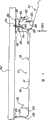
图1是根据本发明第一实施例的覆盖件的透视图;1 is a perspective view of a cover according to a first embodiment of the present invention;
图2是图1中所示的覆盖件作为屋顶板在安装的过程中的前视图;Figure 2 is a front view of the covering shown in Figure 1 as a roof panel during installation;
图3是图2中所示的安装完成后的前视图;Fig. 3 is a front view after the installation shown in Fig. 2 is completed;
图4是图1中所示的覆盖件作为天花板在安装过程中的前视图;Figure 4 is a front view of the covering shown in Figure 1 as a ceiling during installation;
图5是图4中所示的覆盖件在安装后的前视图;Figure 5 is a front view of the cover shown in Figure 4 after installation;
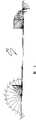
图6是图1中所示的覆盖件的辊轧成形的花图式;和FIG. 6 is a roll-formed flower diagram of the cover shown in FIG. 1; and
图7是根据本发明第二实施例的覆盖件的局部前视图。Fig. 7 is a partial front view of a cover according to a second embodiment of the present invention.
具体实施方式Detailed ways
首先参考图1,示出有根据本发明的覆盖件10的第一实施例。元件10由0.42mm基底金属厚度(BMT)的钢板带形成,优选地,通过辊轧成形生产元件10,如将参考图6更详细描述的。Referring first to FIG. 1 , there is shown a first embodiment of a
元件10具有基本平坦的中央腹板12,中央腹板12的凸状肋构造14沿着一个纵向边缘延伸,而其凹状肋构造16沿着另一个纵向边缘延伸。当元件10用作屋顶板或天花板时,腹板侧12’是最低的部分(即,下侧),当元件10用作墙壁覆盖件时,从覆盖房间内部可以看见腹板侧12’。The
腹板12还具有一对纵向延伸的、基本平行的、隔开的较小的加强肋18,加强肋18在与凸状肋构造和凹状肋构造14、16相同的方向上凸起。The
该腹板大约260mm宽,加强肋18大约12mm宽且远离肋的平面大约5mm地延伸。凸状肋构造14大约26mm宽,且远离腹板12的平面大约44mm地延伸。凹状肋构造大约37mm宽,且远离腹板12的平面大约45mm地延伸。通常以大约6米的长度生产元件10,其长度可达大约9.6米(通常受到运输限制)。The web is about 260mm wide and the reinforcing
凸状肋构造14包括内直立肋20,在内直立肋20的远端上具有成角度(或倾斜)的凸缘22,凸缘22向内且朝着腹板12成一定角度。凸状肋构造14还包括外直立肋24,在外直立肋24的远端上具有向外指向的凸缘26,而在外直立肋24的近端上具有向外凸起的槽道28。除了内肋20之外,凸状肋构造14的厚度是腹板12的厚度的两倍,且通过将腹板折叠起来并折回到本身上来形成凸状肋构造14,如从图6中将会变得更加明显。该折叠有利地允许由一片单独的钢材形成元件10。The
凹状肋构造16具有内直立肋30,在内直立肋30的远端上具有向外凹的凹部32,而在内直立肋30的近端上具有向内凹的槽道34。连接部分36从内肋30的远端向外延伸且基本上与腹板12平行,并从腹板12移开一定距离。外肋38从连接部分36下垂且在其远端具有成角度(或倾斜)的凸缘40,凸缘40向内且远离腹板12成一角度。The concave rib formation 16 has an inner
在所示的优选实施例中,元件10的薄金属板结构导致凸状肋构造和凹状肋构造14、16的不同组成部分可在负荷下弹性弯曲,并能从图1中所示的位置和方位移开并在不再遭受负荷时弹性返回到那些方位。In the preferred embodiment shown, the thin sheet metal construction of the
图2表示在作为屋顶板安装且固定到支承板条42的过程中的覆盖件10和同样的覆盖件10’。安装过程始于在凸状肋构造14附近通过紧固件如自攻丝螺钉/自钻孔螺钉44固定覆盖件10,螺钉44在凸状肋构造14的内肋和外肋20与24之间被驱动发射到元件10上,覆盖件10’的凹状肋部16压在覆盖件10的凸状肋部14上面并与其锁定接合。在该接合过程中,肋38如箭头46所示地向外弯曲,而肋20通常如箭头48所示地向内弯曲,直到成角度的凸缘22被接纳与成角度的凸缘40接合,如图3中所示。当这种情况发生时,凸缘26也位于凹部32内,而槽道28位于槽道34内。在接合过程中,肋构造24和30也可以有一些弯曲,总体地如箭头50和52所示。还可通过在开始使元件10’倾斜远离元件10以在开始将凸缘22定位成与凸缘40接合,然后通常如箭头54所示地枢转凸状肋构造和凹状肋构造14与16的剩余部分使它们彼此接合,来帮助接合过程。Figure 2 shows the covering 10 and the same covering 10' The installation process begins by securing the
这样,通过按照类似的方法,接续的元件能顺序地附接到另一个元件上。优选地,通过在开始将覆盖件10的仅仅包括凸状肋构造14(未示出)的一个部分固定和以前述方式使覆盖件10与该构造14接合,将元件10的右手端固定到板条42。Thus, by following a similar method, successive elements can be sequentially attached to another element. Preferably, the right-hand end of the
参考图3,可以看到在装配之后,凸状肋构造和凹状肋构造14、16形成基本为矩形的封闭槽道56,其有利地将螺钉44隐藏起来,这有利地消除了对已知的覆盖板所需的任何额外的隐藏固定装置或夹子的需要。此外,靠近凹部28、32的板材在槽道56的底部左手角部形成向下凹的凹部58,槽道56基本上复制了加强肋18提供的槽道,并因此当在箭头60的方向上观察时,给覆盖件10、10’等等提供了统一的表面外观。Referring to Figure 3, it can be seen that after assembly, the male and
现在将参考图4和5描述覆盖件10作为天花板的安装,图4和5用相同的附图标记表示图1到3中的相同结构特征。The installation of the
首先看图4,最初通过使螺钉44穿过凹状肋构造16的连接部分36,将元件10紧固到板条42。然后,将覆盖件10’引入到图4中通常示出的位置中,并在箭头60的方向上进行操纵使其与元件10的凹状肋构造16接合,如图5中所示。在接合过程中,肋20和40弯曲,如箭头46和48通常表示的。肋24也可以有一些轻微的弯曲,如箭头50通常表示的。肋30通常不会弯曲,因为它被板条42的元件10的联接所约束。Referring first to FIG. 4 , the
如同屋顶板的安装一样,在装配之后,凸状肋构造和凹状肋构造14、16形成基本为矩形的封闭槽道56,其将螺钉44隐藏起来。此外,还是与屋顶板的安装相似,凸状肋构造和凹状肋构造14、16也形成向下凸起的凹部58,凹部58复制了肋18所提供的形状,从而当在箭头60的方向上观察时,提供统一而漂亮的天花板外观。通过与预先固定到板条42上的凹状肋构造16(未示出)的接合,覆盖件10的左手端初始被固定到板条42上。As with the installation of shingles, after assembly, the male and
图4和5还表现了元件10作为墙壁覆层安装的顶视图,其中腹板12的表面12’将统一看得见的表面呈现给覆盖房间的内部。Figures 4 and 5 also represent a top view of the installation of the
与依靠暴露的紧固件头和覆盖板之间的橡胶垫片的已知覆盖板相比,此封闭槽道56的形成还提高了防漏性。此外,当屋顶安装者为了与屋顶覆层齐平安装而开出瓦片齐平槽时,基本为矩形的槽56的形状更容易使得开出的齐平槽一致,这使得安装时间减少和使得产生间隙以及相关泄漏的机会更小。The formation of this
如上所述,元件10优选地由一片单片金属通过与图6的辊轧成形花图示中所示的过程相一致的辊轧成形形成。As noted above,
现在参考图7,示出了根据本发明的覆盖件70的第二实施例。用在描述第一实施例中所用的相同附图标记来表示第二实施例中的相同结构特征。Referring now to FIG. 7 , a second embodiment of a
元件70也由0.42mm基底金属厚度(BMT)的钢板带形成,并通过参考图6所述的辊轧成形过程生产,辊轧成形过程包括将腹板12折回到本身上以形成凸状肋构造14,这也导致在内直立肋和外直立肋20与24之间有两个相邻的腹板层72和74。
在元件70中,将6mm宽的粘合带76(涂黑的区域)插入到层72和74之间以防止它们分离。粘合带优选地是3M公司销售的VHB(商标)胶带。在辊轧成形过程中,将胶带供给到辊轧成形机中。也可使用Jetweld TS230胶水,但带容易结合到辊轧成形过程中。In
如上所述,粘合带76防止两个腹板层72和74分离,当与元件10相比时,这有利地允许安装在固定物之间的元件70具有更长的跨距。另外,当以相似的固定间隔安装时,元件70能比元件10经受住更高的风力载荷。As noted above, the
虽然已经参考优选实施例对本发明进行了描述,但本领域技术人员应该理解,能以许多其它形式实施本发明,例如,虽然凸状肋构造和凹状肋构造在覆盖件的整个长度上延伸是优选的,但它不是必需的,替换方式是一系列不连续的在长度上间隔开的凸状肋构造和凹状肋构造。此外,元件也可以由塑料板或其它材料板形成。Although the invention has been described with reference to a preferred embodiment, those skilled in the art will appreciate that the invention can be embodied in many other forms, for example, although it is preferred that the male and female rib configurations extend the entire length of the cover. Yes, but it is not required, the alternative is a series of discrete convex and concave rib formations spaced along the length. Furthermore, the elements may also be formed from sheets of plastic or other materials.
Claims (17)
Translated fromChineseApplications Claiming Priority (2)
| Application Number | Priority Date | Filing Date | Title |
|---|---|---|---|
| AU2002953172AAU2002953172A0 (en) | 2002-12-04 | 2002-12-04 | A Cladding Element |
| AU2002953172 | 2002-12-04 |
Publications (2)
| Publication Number | Publication Date |
|---|---|
| CN1745223A CN1745223A (en) | 2006-03-08 |
| CN100482907Ctrue CN100482907C (en) | 2009-04-29 |
Family
ID=29408893
Family Applications (1)
| Application Number | Title | Priority Date | Filing Date |
|---|---|---|---|
| CNB2003801095117AExpired - Fee RelatedCN100482907C (en) | 2002-12-04 | 2003-12-04 | covering element |
Country Status (12)
| Country | Link |
|---|---|
| US (1) | US20060144002A1 (en) |
| EP (1) | EP1573146A4 (en) |
| JP (1) | JP2006509122A (en) |
| KR (1) | KR20050084158A (en) |
| CN (1) | CN100482907C (en) |
| AU (1) | AU2002953172A0 (en) |
| BR (1) | BR0317017A (en) |
| CA (1) | CA2508599A1 (en) |
| MX (1) | MXPA05005960A (en) |
| NZ (1) | NZ540990A (en) |
| WO (1) | WO2004051025A1 (en) |
| ZA (1) | ZA200504855B (en) |
Families Citing this family (13)
| Publication number | Priority date | Publication date | Assignee | Title |
|---|---|---|---|---|
| US7464511B2 (en)* | 2002-12-12 | 2008-12-16 | Paul James Kosch | Slat wall assembly |
| US20110061323A1 (en)* | 2009-07-29 | 2011-03-17 | Exterior Building Products, LLC | Simulated Masonry Wall Panel with Improved Seam Integration |
| FR2977509B1 (en)* | 2011-07-04 | 2014-04-25 | Mapac Panel | HOLDING DEVICE FOR CONTINUOUS STATE HOLDING OF PLATE, BUILDING ELEMENT, AND METHOD OF MANUFACTURING SUCH BUILDING ELEMENT |
| CN102979257B (en)* | 2012-12-25 | 2014-09-03 | 上海亚泽金属屋面系统股份有限公司 | Splicing method for metal roof profiled flat plate |
| US9267289B2 (en)* | 2013-03-08 | 2016-02-23 | Quality Edge, Inc. | Formed interlocking roofing panels |
| FI126730B (en) | 2013-05-02 | 2017-04-28 | Luxhammar Oy | Method and board module for making a wood heat treatment furnace and a wood heat treatment furnace |
| JP6879753B2 (en)* | 2017-02-03 | 2021-06-02 | 株式会社Lixil | Roof structure and construction method of roof structure |
| EP3600815B1 (en)* | 2017-03-29 | 2024-10-30 | Compagnie Générale des Etablissements Michelin | Dual mold spacer |
| CN107842148A (en)* | 2017-11-10 | 2018-03-27 | 中铁第四勘察设计院集团有限公司 | A kind of roof board system for improving water resistance |
| CN108867893A (en)* | 2018-07-11 | 2018-11-23 | 合肥皖信信息工程有限责任公司 | A kind of waterproof leakproof pallet for computer room ceiling |
| NO345137B1 (en)* | 2018-07-13 | 2020-10-12 | Arild Hardeng | Wet room element, wet room with said element for use in the floor, wall and roof, and method for manufacturing said wet room elements. |
| US12264479B2 (en)* | 2020-12-07 | 2025-04-01 | ACM Panelworx Inc. | Modular panels, systems, and methods of assembly |
| EP4343073A1 (en)* | 2022-09-20 | 2024-03-27 | Rautaruukki Oyj | Roof panel |
Citations (5)
| Publication number | Priority date | Publication date | Assignee | Title |
|---|---|---|---|---|
| AU1812676A (en)* | 1976-09-27 | 1978-04-06 | Alumax Inc. | Roofing of cladding sheets |
| AU7673881A (en)* | 1980-10-22 | 1982-04-29 | John De Jongh | Cladding |
| US4561233A (en)* | 1983-04-26 | 1985-12-31 | Butler Manufacturing Company | Wall panel |
| CN2208596Y (en)* | 1994-06-16 | 1995-09-27 | 金伍兴实业股份有限公司 | Combined corrugated board with novel connection structure |
| CN2368901Y (en)* | 1998-10-09 | 2000-03-15 | 九唯钢品有限公司 | Insulation wave board |
Family Cites Families (34)
| Publication number | Priority date | Publication date | Assignee | Title |
|---|---|---|---|---|
| US3524292A (en)* | 1968-02-07 | 1970-08-18 | Alumna Kraft Mfg Co | Interlocking panel assembly |
| GB1321609A (en)* | 1969-08-21 | 1973-06-27 | Ici Ltd | Foam laminates |
| US3733767A (en)* | 1971-04-21 | 1973-05-22 | Teledyne Inc | Interlocking panel assembly |
| GB1387272A (en)* | 1971-10-08 | 1975-03-12 | Cookson Sheet Metal Dev Ltd | Sheet fixing devices |
| JPS5223370Y2 (en)* | 1973-06-21 | 1977-05-28 | ||
| AU506471B2 (en)* | 1976-06-23 | 1980-01-03 | Otto Zambelli Pty Ltd | Metal cladding |
| US4109437A (en)* | 1977-03-30 | 1978-08-29 | Howmet Corporation | Building panel |
| US4192117A (en)* | 1977-05-18 | 1980-03-11 | Heinrich William C | Spring action panel interlock |
| US4091588A (en)* | 1977-05-18 | 1978-05-30 | Heirich William C | Spring action panel interlock |
| PH14992A (en)* | 1978-10-26 | 1982-03-15 | Lysaght Australia Ltd | Cladding sheets |
| US4266385A (en)* | 1979-06-01 | 1981-05-12 | Oehlert James A | Interlocking building panel construction |
| JPS5733827U (en)* | 1980-08-06 | 1982-02-22 | ||
| JPS59124229U (en)* | 1982-12-27 | 1984-08-21 | 戸田 直彦 | roof equipment |
| ZA832689B (en)* | 1983-03-29 | 1984-01-25 | Wilfried Josef Schenach | Roof cladding |
| US4522007A (en)* | 1983-11-17 | 1985-06-11 | Oehlert James A | Interlocking building panel |
| US5697197A (en)* | 1984-01-04 | 1997-12-16 | Harold Simpson, Inc. | Roof panel system having increased resistance to wind loads |
| AU583046B2 (en)* | 1984-06-28 | 1989-04-20 | Blazley Designs Pty Ltd | Arcuate building panel joint |
| US4896466A (en)* | 1984-06-28 | 1990-01-30 | Blazley Designs Pty. Ltd. | Construction method and apparatus |
| CA1248320A (en)* | 1985-09-17 | 1989-01-10 | James W. Harter | Wall panel |
| JPH0524742Y2 (en)* | 1986-05-26 | 1993-06-23 | ||
| US4878331A (en)* | 1987-07-28 | 1989-11-07 | Janet R. Taylor | Metal roofing structure |
| US5201158A (en)* | 1988-05-13 | 1993-04-13 | British Alcan Aluminium Plc | Metal sheeting |
| US4918898A (en)* | 1989-02-07 | 1990-04-24 | Mcleod Jr John D | Building panel |
| GB2245618B (en)* | 1990-07-06 | 1994-04-06 | Euroclad South Wales Ltd | Building covering |
| JPH0726448U (en)* | 1993-10-20 | 1995-05-19 | 直彦 戸田 | Roofing equipment |
| US6134855A (en)* | 1994-05-13 | 2000-10-24 | Certainteed Corporation | Apparatus and method of applying building panels to surfaces |
| US5524409A (en)* | 1994-12-02 | 1996-06-11 | Kaiser; Heinz W. | Roofing and siding panel construction |
| EP1197610A3 (en)* | 1995-08-25 | 2003-05-07 | Gantan Beauty Industry Co., Ltd. | Longitudinal facing, facing retainers, and facing structure having facing and facing retainers |
| US5725201A (en)* | 1995-12-11 | 1998-03-10 | North American Pipe Corporation | Adjustable width panel assembly |
| US6128866A (en)* | 1996-11-08 | 2000-10-10 | Wearne; John R. | Identifying prefabricated exterior siding and related trim items |
| JP3052904B2 (en)* | 1997-07-18 | 2000-06-19 | アキレス株式会社 | Insulated metal panel |
| US6122878A (en)* | 1999-04-22 | 2000-09-26 | Pliley; Robert | Seamless siding system and method |
| MXPA03009032A (en)* | 2001-04-03 | 2004-02-12 | James Hardie Res Pty Ltd | Fiber cement siding planks, methods of making and installing. |
| US6543197B2 (en)* | 2001-08-10 | 2003-04-08 | Arrow Group Industries, Inc. | Snap-fit panel connection apparatus |
- 2002
- 2002-12-04AUAU2002953172Apatent/AU2002953172A0/ennot_activeAbandoned
- 2003
- 2003-12-04EPEP03776652Apatent/EP1573146A4/ennot_activeWithdrawn
- 2003-12-04BRBR0317017-9Apatent/BR0317017A/enunknown
- 2003-12-04USUS10/536,930patent/US20060144002A1/ennot_activeAbandoned
- 2003-12-04MXMXPA05005960Apatent/MXPA05005960A/enactiveIP Right Grant
- 2003-12-04ZAZA200504855Apatent/ZA200504855B/enunknown
- 2003-12-04WOPCT/AU2003/001611patent/WO2004051025A1/enactiveApplication Filing
- 2003-12-04NZNZ540990Apatent/NZ540990A/enunknown
- 2003-12-04JPJP2004555874Apatent/JP2006509122A/ennot_activeWithdrawn
- 2003-12-04CNCNB2003801095117Apatent/CN100482907C/ennot_activeExpired - Fee Related
- 2003-12-04KRKR1020057010131Apatent/KR20050084158A/ennot_activeCeased
- 2003-12-04CACA002508599Apatent/CA2508599A1/ennot_activeAbandoned
Patent Citations (5)
| Publication number | Priority date | Publication date | Assignee | Title |
|---|---|---|---|---|
| AU1812676A (en)* | 1976-09-27 | 1978-04-06 | Alumax Inc. | Roofing of cladding sheets |
| AU7673881A (en)* | 1980-10-22 | 1982-04-29 | John De Jongh | Cladding |
| US4561233A (en)* | 1983-04-26 | 1985-12-31 | Butler Manufacturing Company | Wall panel |
| CN2208596Y (en)* | 1994-06-16 | 1995-09-27 | 金伍兴实业股份有限公司 | Combined corrugated board with novel connection structure |
| CN2368901Y (en)* | 1998-10-09 | 2000-03-15 | 九唯钢品有限公司 | Insulation wave board |
Also Published As
| Publication number | Publication date |
|---|---|
| CA2508599A1 (en) | 2004-06-17 |
| CN1745223A (en) | 2006-03-08 |
| US20060144002A1 (en) | 2006-07-06 |
| ZA200504855B (en) | 2008-01-30 |
| KR20050084158A (en) | 2005-08-26 |
| BR0317017A (en) | 2005-10-25 |
| MXPA05005960A (en) | 2006-01-27 |
| AU2002953172A0 (en) | 2002-12-19 |
| WO2004051025A1 (en) | 2004-06-17 |
| NZ540990A (en) | 2006-11-30 |
| JP2006509122A (en) | 2006-03-16 |
| EP1573146A1 (en) | 2005-09-14 |
| EP1573146A4 (en) | 2009-08-05 |
Similar Documents
| Publication | Publication Date | Title |
|---|---|---|
| US7694478B2 (en) | Panel attachment system | |
| CN100482907C (en) | covering element | |
| CA2534779A1 (en) | Building panel | |
| US20090241458A1 (en) | Siding Panel Assembly With Splicing Member and Insulating Panel | |
| US6568144B2 (en) | Metal construction panel | |
| US5570555A (en) | Double batted roof structure | |
| US5410849A (en) | Modified insulated panel | |
| WO1999016985A1 (en) | Roof cladding element, system and use of the elements | |
| JP3659358B2 (en) | Roof renovation structure | |
| WO1997040243A1 (en) | Cladding element | |
| AU2003285978B2 (en) | A cladding element | |
| JP3164222B2 (en) | Downward cap | |
| AU711048C (en) | Cladding element | |
| JPH10212799A (en) | Structure of waterproof joint | |
| AU2005100762A4 (en) | Architectural Panel with Reinforcement Backing | |
| JP3015651U (en) | Roof renovation structure | |
| JP3569790B2 (en) | Roof repair structure | |
| AU711048B2 (en) | Cladding element | |
| JP3533615B2 (en) | Roof structure | |
| JPH0726669A (en) | Waterproof joint material | |
| JP3597278B2 (en) | Roofing material | |
| JP2001090327A (en) | Floor finishing material, floor finishing method and unit building floor finishing method | |
| JPH0539653A (en) | Descending ridge envelope | |
| JP3604100B2 (en) | Roofing material | |
| JPH0717700Y2 (en) | Insulation panel |
Legal Events
| Date | Code | Title | Description |
|---|---|---|---|
| C06 | Publication | ||
| PB01 | Publication | ||
| C10 | Entry into substantive examination | ||
| SE01 | Entry into force of request for substantive examination | ||
| C14 | Grant of patent or utility model | ||
| GR01 | Patent grant | ||
| C17 | Cessation of patent right | ||
| CF01 | Termination of patent right due to non-payment of annual fee | Granted publication date:20090429 Termination date:20121204 |