CN100480979C - Storage system and storage control method - Google Patents
Storage system and storage control methodDownload PDFInfo
- Publication number
- CN100480979C CN100480979CCNB2006100584003ACN200610058400ACN100480979CCN 100480979 CCN100480979 CCN 100480979CCN B2006100584003 ACNB2006100584003 ACN B2006100584003ACN 200610058400 ACN200610058400 ACN 200610058400ACN 100480979 CCN100480979 CCN 100480979C
- Authority
- CN
- China
- Prior art keywords
- breaking
- logic section
- section bulk
- order
- raid
- Prior art date
- Legal status (The legal status is an assumption and is not a legal conclusion. Google has not performed a legal analysis and makes no representation as to the accuracy of the status listed.)
- Expired - Fee Related
Links
Images


Classifications
- G—PHYSICS
- G06—COMPUTING OR CALCULATING; COUNTING
- G06F—ELECTRIC DIGITAL DATA PROCESSING
- G06F3/00—Input arrangements for transferring data to be processed into a form capable of being handled by the computer; Output arrangements for transferring data from processing unit to output unit, e.g. interface arrangements
- G06F3/06—Digital input from, or digital output to, record carriers, e.g. RAID, emulated record carriers or networked record carriers
- G06F3/0601—Interfaces specially adapted for storage systems
- G06F3/0628—Interfaces specially adapted for storage systems making use of a particular technique
- G06F3/0655—Vertical data movement, i.e. input-output transfer; data movement between one or more hosts and one or more storage devices
- G06F3/0658—Controller construction arrangements
- G—PHYSICS
- G06—COMPUTING OR CALCULATING; COUNTING
- G06F—ELECTRIC DIGITAL DATA PROCESSING
- G06F3/00—Input arrangements for transferring data to be processed into a form capable of being handled by the computer; Output arrangements for transferring data from processing unit to output unit, e.g. interface arrangements
- G06F3/06—Digital input from, or digital output to, record carriers, e.g. RAID, emulated record carriers or networked record carriers
- G06F3/0601—Interfaces specially adapted for storage systems
- G06F3/0602—Interfaces specially adapted for storage systems specifically adapted to achieve a particular effect
- G06F3/0614—Improving the reliability of storage systems
- G06F3/0617—Improving the reliability of storage systems in relation to availability
- G—PHYSICS
- G06—COMPUTING OR CALCULATING; COUNTING
- G06F—ELECTRIC DIGITAL DATA PROCESSING
- G06F3/00—Input arrangements for transferring data to be processed into a form capable of being handled by the computer; Output arrangements for transferring data from processing unit to output unit, e.g. interface arrangements
- G06F3/06—Digital input from, or digital output to, record carriers, e.g. RAID, emulated record carriers or networked record carriers
- G06F3/0601—Interfaces specially adapted for storage systems
- G06F3/0668—Interfaces specially adapted for storage systems adopting a particular infrastructure
- G06F3/067—Distributed or networked storage systems, e.g. storage area networks [SAN], network attached storage [NAS]
- H—ELECTRICITY
- H04—ELECTRIC COMMUNICATION TECHNIQUE
- H04L—TRANSMISSION OF DIGITAL INFORMATION, e.g. TELEGRAPHIC COMMUNICATION
- H04L45/00—Routing or path finding of packets in data switching networks
- H—ELECTRICITY
- H04—ELECTRIC COMMUNICATION TECHNIQUE
- H04L—TRANSMISSION OF DIGITAL INFORMATION, e.g. TELEGRAPHIC COMMUNICATION
- H04L45/00—Routing or path finding of packets in data switching networks
- H04L45/46—Cluster building
Landscapes
- Engineering & Computer Science (AREA)
- Theoretical Computer Science (AREA)
- Human Computer Interaction (AREA)
- Physics & Mathematics (AREA)
- General Engineering & Computer Science (AREA)
- General Physics & Mathematics (AREA)
- Computer Networks & Wireless Communication (AREA)
- Signal Processing (AREA)
- Information Retrieval, Db Structures And Fs Structures Therefor (AREA)
- Debugging And Monitoring (AREA)
- Data Exchanges In Wide-Area Networks (AREA)
Abstract
Translated fromChinese
Description
Translated fromChinese技术领域technical field
本发明涉及一种存储控制技术。The invention relates to a storage control technology.
背景技术Background technique
作为与存储系统有关的技术,例如公知在特开2001—256003号公报、特开2003—140837号公报、特开平8—328760号公报、特开平10—63576号公报以及特开2002—123479号公报中公开的技术。As technologies related to storage systems, for example, JP-A-2001-256003, JP-A-2003-140837, JP-A-8-328760, JP-A-10-63576, and JP-A-2002-123479 are known. technology disclosed in .
但是,作为可以在存储系统中采用的体系结构,例如具有公共存储器体系结构或分散存储器体系机构。However, as an architecture that can be adopted in the storage system, there is, for example, a common memory architecture or a distributed memory architecture.
根据公共存储器体系结构,在公共存储器中存储与存储系统有关的各种各样的信息,存储系统内的哪个接口基板(例如对于主机装置的接口基板、以及对于媒体驱动器的接口基板)都可以访问公共存储器内的信息。但是,因此向公共存储器的访问就会集中,成为瓶颈。According to the common memory architecture, various information related to the storage system is stored in the common memory, which can be accessed by any interface board in the storage system (such as the interface board for the host device and the interface board for the media drive) Information in Public Storage. However, access to the common memory is therefore concentrated and becomes a bottleneck.
根据分散存储器体系结构,存在具有路由选择以及交换功能的上位的路由器以及交换机部,和分割了RAID结构的下位的多个模块。上位的路由器/交换机部从主机装置接收命令,并对该命令进行分析,判断访问多个模块中的哪一个,可以访问多个模块中的一个或多个的模块。但是,因此路由器/交换机部的负荷就会增大。此外,一个RAID的结构是由多个模块提供的,所以在一个模块发生了故障的情况下,其它模块即使正常RAID结构也被破坏。According to the distributed memory architecture, there are an upper router and a switch unit having routing and switching functions, and a plurality of lower modules that divide the RAID structure. The upper router/switch unit receives a command from the host device, analyzes the command, determines which of the multiple modules to access, and can access one or more of the multiple modules. However, this increases the load on the router/switch unit. In addition, a RAID structure is provided by multiple modules, so if a module fails, other modules will be destroyed even if the normal RAID structure is present.
【专利文献1】特开2001—256003号公报[Patent Document 1] JP-A-2001-256003 Gazette
【专利文献2】特开2003—140837号公报[Patent Document 2] JP-A-2003-140837 Gazette
【专利文献3】特开平8—328760号公报[Patent Document 3] Japanese Patent Laid-Open No. 8-328760
【专利文献4】特开平10—63576号公报[Patent Document 4] JP-10-63576 Gazette
【专利文献5】特开2002—123479号公报[Patent Document 5] JP-A-2002-123479 Gazette
发明内容Contents of the invention
因此,本发明的目的之一在于提供一种解除了公共存储器体系结构和分散存储器体系结构双方的问题点的新的存储控制技术。Therefore, one object of the present invention is to provide a new memory control technique that solves the problems of both the common memory architecture and the distributed memory architecture.
通过后面的说明,本发明的其他目的将会变得明确。Other objects of the present invention will become clear from the following description.
本发明的存储系统具有:从存在于存储系统外部的外部装置接收命令并进行转发的路由器;多个RAID模块;从所述路由器接收命令后发送给所述多个RAID模块中的某一个的交换机。各个RAID模块具备:多个媒体驱动器;由所述多个媒体驱动器提供的依据RAID组的逻辑部分件;对与所述外部装置之间交换的数据进行存储的存储器;可以对经由所述交换机从所述外部装置接收到的数据、从所述逻辑部分件读出的数据进行存储的存储器;以及处理器。所述处理器根据经由所述交换机从所述外部装置接收到的命令,把所述存储器中存储的数据写入所述逻辑部分件中,或者将所述存储器中存储的数据输出给所述交换机。在该存储系统中,各个RAID模块不横跨其他RAID模块地单独具备RAID组。所述外部装置可以是主机装置也可以是其他的存储系统。The storage system of the present invention includes: a router that receives and forwards a command from an external device existing outside the storage system; a plurality of RAID modules; and a switch that receives a command from the router and sends it to one of the plurality of RAID modules. . Each RAID module is equipped with: a plurality of media drives; logic components provided by the plurality of media drives according to the RAID group; storage for storing data exchanged with the external device; a memory for storing data received by the external device and data read from the logic part; and a processor. The processor writes the data stored in the memory into the logic part or outputs the data stored in the memory to the switch according to a command received from the external device via the switch . In this storage system, each RAID module independently has a RAID group without straddling other RAID modules. The external device may be a host device or another storage system.
在本发明的一个方式中,所述路由器可以不进行所述命令的分析(例如是写入命令还是读取命令的判断)而对所述命令进行转发。此时,所述各个RAID模块内的所述处理器进行所述命令的分析,可以执行按照该分析结果的处理。In one aspect of the present invention, the router may forward the command without analyzing the command (for example, judging whether it is a write command or a read command). At this time, the processors in the respective RAID modules analyze the commands, and may execute processing according to the analysis results.
在本发明的一个方式中,所述路由器可以具有:不进行所述命令的分析而控制所述命令的转发的命令转发电路(例如转发单元);可以存储用于对命令的转发进行控制的转发控制信息的存储区域(例如存储单元)。在所述转发控制信息中,用于确定命令的转发目的地的路径数据可以与每个用于识别逻辑部分件的各逻辑部分件ID相对应。所述命令转发电路可以从所述外部装置接收逻辑部分件ID以及命令,由所述转发控制信息确定与该逻辑部分件ID相对应的路径数据,并根据已确定的路径数据转发所述接收到的命令。In one aspect of the present invention, the router may have: a command forwarding circuit (such as a forwarding unit) that controls forwarding of the command without analyzing the command; and may store a forwarding circuit for controlling forwarding of the command. A storage area (such as a storage unit) for control information. In the forwarding control information, path data for determining a forwarding destination of a command may correspond to each logical component ID for identifying a logical component. The command forwarding circuit may receive a logical component ID and a command from the external device, determine the path data corresponding to the logical component ID from the forwarding control information, and forward the received command according to the determined path data. The command.
所述各个RAID模块可以具备可以对各个逻辑部分件ID进行存储的存储资源(例如存储单元),该各个逻辑部分件ID表示在该RAID模块中存在的各个逻辑部分件。所述各个RAID模块(例如处理器)在所述存储资源中存在逻辑部分件ID的更新时,可以将更新请求和与更新有关的逻辑部分件ID发送给所述交换机。所述交换机可以将所述更新请求和与所述更新有关的逻辑部分件ID发送给所述路由器。所述路由器可以接收所述更新请求和与所述更新有关的逻辑部分件ID,并根据所述更新请求,使用所述已接收到的逻辑部分件ID更新所述转发控制信息。Each RAID module may have a storage resource (such as a storage unit) capable of storing each logical component ID, and each logical component ID indicates each logical component existing in the RAID module. Each RAID module (such as a processor) may send an update request and a logical component ID related to the update to the switch when there is an update of the logical component ID in the storage resource. The switch may send the update request and the logical component ID related to the update to the router. The router may receive the update request and the logical component ID related to the update, and update the forwarding control information by using the received logical component ID according to the update request.
这里,所述路由器可以具备缓冲存储器。所述路由器即使在接收到所述更新请求的情况下,也可以从所述外部装置接收命令,如果从所述外部装置接收到了命令,则将所述接收到的命令积蓄在所述缓冲存储器中,在所述转发控制信息的更新已结束的情况下,根据更新后的转发控制信息转发积蓄在所述缓冲存储器中的各个命令。Here, the router may include a buffer memory. The router may receive a command from the external device even when the update request is received, and if the command is received from the external device, store the received command in the buffer memory. In a case where the update of the forwarding control information has been completed, each command stored in the buffer memory is forwarded according to the updated forwarding control information.
此外,所述RAID模块可以对所述更新请求进行广播。In addition, the RAID module may broadcast the update request.
在本发明的一个方式中,所述各个RAID模块可以具备表示各个逻辑部分件ID和各个媒体驱动器ID的对应的构成信息(例如可以具备构成信息存储单元)。在所述各个RAID模块所具备的构成信息中包含存在于具有该构成信息的RAID模块中的逻辑部分件以及媒体驱动器各自的ID就可以,也可以不包含存在于其他RAID模块中的逻辑部分件以及媒体驱动器各自的ID。所述处理器可以由所述构成信息确定与从所述交换机接收到的逻辑部分件ID相对应的媒体驱动器ID,来访问与所述确定的媒体驱动器ID相对应的媒体驱动器。In one aspect of the present invention, each of the RAID modules may include configuration information indicating correspondence between each logical component ID and each media drive ID (for example, may include a configuration information storage unit). The configuration information of each RAID module may include the IDs of the logical components in the RAID module having the configuration information and the IDs of the media drives, or may not include the logical components in other RAID modules. and the respective IDs of the media drives. The processor may determine a media drive ID corresponding to the logical component ID received from the switch from the configuration information to access the media drive corresponding to the determined media drive ID.
根据本发明,提供一种解除了公共存储器体系结构和分散存储器体系结构双方的问题点的新的存储控制技术。According to the present invention, there is provided a new memory control technique that solves the problems of both the common memory architecture and the distributed memory architecture.
附图说明Description of drawings
图1A表示本发明第一实施方式的整个系统的结构。FIG. 1A shows the configuration of the entire system of the first embodiment of the present invention.
图1B表示存储系统3的结构例。FIG. 1B shows a configuration example of the
图2A表示路由器7的结构例。FIG. 2A shows a configuration example of
图2B表示路由表23的结构例。FIG. 2B shows a configuration example of the routing table 23 .
图2C表示路由器7从主机装置1接收的第一分组组的结构例。FIG. 2C shows a configuration example of the first packet received by the
图2D表示路由器7发送给SW9的第二分组组的结构例。FIG. 2D shows an example of the structure of the second packet sent by the
图3A表示SW9的结构例。FIG. 3A shows a configuration example of SW9.
图3B表示RAID模块11的结构例。FIG. 3B shows a configuration example of the
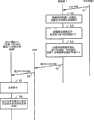
图4表示在存储系统3从主机装置1接收到命令时进行的处理的流程的一个例子。FIG. 4 shows an example of the flow of processing performed when the
图5表示在存储系统3中进行的路由表更新处理的流程的一个例子。FIG. 5 shows an example of the flow of routing table update processing performed in the
图6A表示边界外方式的一个例子。Fig. 6A shows an example of the out-of-boundary mode.
图6B表示第一边界内方式的一个例子。Fig. 6B shows an example of the first in-boundary mode.
图6C表示在本实施方式中所采用的第二边界内方式。FIG. 6C shows the second in-boundary method employed in this embodiment.
图7A是本发明一实施方式的一个变形例的说明图。FIG. 7A is an explanatory diagram of a modified example of the embodiment of the present invention.
图7B是本发明一实施方式的其他变形例的说明图。FIG. 7B is an explanatory diagram of another modified example of the embodiment of the present invention.
具体实施方式Detailed ways
下面,参照附图对本发明的一实施方式进行说明。Hereinafter, an embodiment of the present invention will be described with reference to the drawings.
图1A表示本发明第一实施方式的整个系统的结构例。FIG. 1A shows a configuration example of the entire system of the first embodiment of the present invention.
可以通过通信网络2可通信地连接多台(也可以为1台)主机装置1、1、...和存储系统3。A plurality of (maybe one)
主机装置1例如是具备CPU、存储器以及显示装置等硬件资源的计算机装置(例如服务器)。主机装置1可以对存储系统3发送读出对象数据的读取命令、写入命令以及写入对象数据。The
作为通信网络2可以采用各种各样的通信网络。具体地说,例如通信网络2可以采用SAN(storage Area Network)或者LAN(Local Area Network)。Various communication networks can be used as the
存储系统3例如可以采用像矩阵状地排列多个媒体驱动器而构成的RAID(Redundant Array of Independent Inexpensive Disks)那样的磁盘阵列系统。The
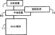
图1B表示存储系统3的结构例。FIG. 1B shows a configuration example of the
在存储系统3中具备:多个协议芯片(在图中略记为「PC」)5、5、...;多个路由器7、7、...;交换机(以下为SW)9;多个RAID模块11、11、...;以及服务处理器(以下为SVP)22。协议芯片5、路由器7以及RAID模块11中的至少一个可以是1个。In the
协议芯片5是对主机装置1和路由器7之间交换的命令进行协议转换的电路。The
路由器7接收由协议芯片5协议转换后的命令(还存在除了命令之外接收数据的情况),进行该命令的路径控制。此外,也可以将上述的协议芯片5内置于路由器7中。The
SW9是对各个路由器7、各个RAID模块11以及SVP22的相互连接进行切换的装置。SW9例如可以采用纵横制SW。在SW9中具有与路由器7连接的两个或多于两个的端口12A、12A、...;和与RAID模块3连接的两个或多于两个的端口12B、12B、...。SW9 is a device for switching the interconnection of each
RAID模块11是具有超高速缓冲存储器、处理器等的组件(如果用别的说法为一组),具有不依存于其他的RAID模块11的RAID结构。即,存在于RAID模块11中的RAID结构与其他的RAID模块11独立,即使在其他的RAID模块11中发生了故障也不会被损坏。这里,RAID结构例如可以为按照规定的RAID等级(例如RAID5)设定的RAID组(例如一个或多个逻辑部分件(以下称为LU))。The
SVP22是可以经由SW9对各个路由器7、各个RAID模块11进行访问的装置。具体地说,例如SVP22是维护用终端,可以具备管理者进行操作的输入装置(例如键盘或鼠标)、按照管理者的操作执行处理的控制装置(例如安装了CPU等的母插件)、显示在RAID模块11、路由器7中设定的信息的显示装置(例如显示器画面)。SVP22可以安装在存储系统3上,也可以经由LAN等通信网路远距离地设置。此外,至少在一个主机装置1上具有SVP22的功能,该主机装置1作为SVP22可以对存储系统3进行控制。SVP22 is a device that can access each
以上是存储系统3的概要。在该实施方式中,为了使下面的说明容易理解设各个路由器7经由SW9与全部的RAID模块11连接,换句话说,设设各个RAID模块11经由SW9与全部的路由器7相连接。The above is the outline of the
下面对该存储系统3所具备的各种要素进行详细地说明。Various elements included in the
图2A表示路由器7的结构例。FIG. 2A shows a configuration example of
路由器7不具备CPU,不对从主机装置1接收到的命令进行分析。这一点是对存储系统3实施的一个办法。路由器7例如是一种电路基板,具备本地存储器(以下称为LM)21和ASIC(Application Specific Integrated Circuit)27。The
LM27是易失性或非易失性存储器。在LM27中例如设置了用于暂时存储经由路由器7交换的分组组(包含命令以及/或者数据)的分组缓冲存储器25。此外,LM27可以存储路由表23。路由表23是用于对来自主机装置1的命令、数据的路径(换句话说是转发目的地)进行控制的信息。如图2B所示,在路由表23中登录多个信息要素集合。在各个信息要素集合中包含逻辑部分件号码(以下为LUN)和端口号码(以下为端口#)。所谓LUN是用于确定LU的号码(也可以是号码以外的ID)。所谓端口#是SW9具备的多个端口中与路由器7相连接的端口12A的号码。此外,LUN以及端口#也可以是号码外之外的ID。LM27 is a volatile or non-volatile memory. For example, a
ASIC27是控制分组组的转发的LSI(Large Scale Integration)。该ASIC27可以为纯粹的硬件电路。ASIC27经由协议芯片5从主机装置1接收图2C所示的第一分组组(例如包含LUN和命令的信息),并且对SW9发送附加了端口#的分组组(例如图2D所示的分组组,以下称为第二分组组)。关于ASIC27所进行的处理在后面参照图4来进行详细的说明。ASIC27 is an LSI (Large Scale Integration) that controls forwarding of packet groups. The ASIC27 can be a pure hardware circuit. The
图3A表示SW9的结构例。FIG. 3A shows a configuration example of SW9.
在SW9中安装了ASIC31,该ASIC31对在路由器7和RAID模块11之间交换的分组组的转发进行控制。ASIC31可以与SVP22连接。SVP22经由该ASIC31可以对各个路由器7或各个RAID模块11进行访问。
图3B表示RAID模块11的结构例。FIG. 3B shows a configuration example of the
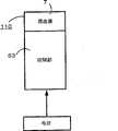
在RAID模块11中具备多个媒体驱动器57、57、...,向各个媒体驱动器57的访问路径被二重化。媒体驱动器57是具备可以存储数据的存储媒体的装置,例如是硬盘驱动器。在RAID模块11中具备控制部53和存储部54。The
在控制部53中具备超高速缓冲存储器(以下称为CM)51、二重化的转发控制LSI49、二重化的磁盘控制器41、41。控制部53例如可以由一个或多个电路基板构成。The
CM51是可以对在路由器7和媒体驱动器57之间交换的数据进行存储的存储器。此外,CM51也可以存储与具有自己的RAID模块(以下称为该模块)11的结构有关的构成信息。如果换一种说法,由于该RAID模块11从其他的RAID模块11中独立出来,所以CM51无需存储与其他的RAID模块11有关的构成信息。The
转发控制LSI49例如是集线器,控制CM51、控制器41、媒体驱动器57以及SW9之间的分组组的转发。The forwarding
控制器41控制对各个媒体驱动器57的数据的输入输出。在控制器41中例如具有:微处理器(以下称为MP)43、引导(boot)存储器45以及LM47。引导存储器45存储了MP43的启动用程序。MP43可以通过从引导存储器45读取该程序来进行启动。此外,MP43例如通过从LM47读入控制程序并执行该控制程序,可以发挥存储虚拟化功能(例如把两个或多于两个的媒体驱动器57作为一个存储资源提供给主机装置1的功能)。LM47用作MP43的工作区域。LM47可以代替CM51存储构成信息。The
存储部54中具备:所述多个媒体驱动器57;对各个媒体驱动器57和控制部53之间的通信进行控制的交换机(例如,光纤通道交换机(以下称为FSW)55)。在多个媒体驱动器57设定作为逻辑存储设备的逻辑部分件(LU)61。图3B中表示一个LU61,但是当然可以设定多个LU61。The
以下,对在存储系统3中进行的各种各样的处理流程进行说明。The flow of various processes performed in the
图4表示在存储系统3从主机装置1接收到命令时进行的处理的流程的一个例子。FIG. 4 shows an example of the flow of processing performed when the
主机装置1对存储系统3发送第一分组组(步骤S1)。具体地说,例如主机装置1对存储系统3发送对作为访问目的地(例如数据的写入目的地或读出源)的LUN进行了指定的命令(例如写入命令或读取命令)。The
存储系统3的路由器7经由协议芯片5从主机装置1接收第一分组组。路由器7的ASIC27将接收到的第一分组组积蓄在LM21内的分组缓冲存储器25中(S2)。The
然后,ASIC27根据路由表23确定与第一分组组内的LUN相对应的端口#(S3)。具体地说,例如ASIC27确定与第一分组组内的LUN相对应的、并且与不是占线状态的端口12A对应的端口#。Then, the
ASIC27从分组缓冲存储器25读出第一分组组,并对所读出的第一分组组附加在S3中确定的端口#来作为第二分组组(S4),然后将第二分组组发送给与该端口#对应的SW9的端口12A(S5)。ASIC27 reads out the first packet group from the
SW9的ASIC31经由某个端口12A接收第二分组组,并把接收到的第二分组组经由与某个端口12A对应的端口12B发送给与该端口12B相连接的RAID模块11(S6)。The
在接收到第二分组组的RAID模块11中,转发控制LSI49把第二分组组内的命令转发给控制器41。如果在第二分组组内包含了写入对象数据,则转发控制LSI49将写入对象数据写入CM51。In the
控制器41的MP43从转发控制LSI49接收命令,并对接收到的命令进行分析(S7)。具体地说,例如MP43判断接收到的命令是写入命令还是读取命令。The MP43 of the
在RAID模块11内执行与MP43的判断结果是写入命令还是读取命令相对应的处理(S8)。In the
例如,在MP43判断为是读取命令的情况下,MP43可以对构成与第二分组组内的LUN对应的LU61的各个媒体驱动器57请求由读取命令所指定的读出对象数据。例如可以通过参照已经写入了LUN和媒体驱动器ID的对应关系的构成信息71(参照图5)来确定构成该LU61的各个媒体驱动器57是哪一个。从接收到请求的各个媒体驱动器57读出所请求的数据,读出的数据经由转发控制LSI49被写入CM51。然后,该数据被从CM51读出,经由转发控制LSI49发送给输出了第二分组组的端口12B。由此,经由SW9以及路由器7对读出命令的发行源的主机装置1发送读出对象数据。For example, when the
另一方面,在MP43判断为是写入命令的情况下,MP43使转发控制LSI49把在CM51中写入的写入对象数据向构成与第二分组组内的LUN对应的LU61的各个媒体驱动器57写入。由此,在CM51中写入的写入对象数据经由转发控制LSI49被写在构成LU61的各个媒体驱动器57中。On the other hand, when the MP43 determines that it is a write command, the MP43 causes the transfer control LSI49 to transfer the write target data written in the CM51 to each media drive 57 constituting the LU61 corresponding to the LUN in the second group group. write. Thereby, the write target data written in CM51 is written in each media drive 57 which comprises LU61 via transfer control LSI49.
以上是存储系统3从主机装置1接收到命令时进行的处理的流程的一个例子。根据该处理,在路由器7中设定了将转发路径与各个LUN相对应起来的路由表23。路由器7根据路由表23确定与主机装置1所指定的LUN对应的转发路径,可以使命令通过该转发路径。具体地说,作为转发路径设定了SW9的端口12A的端口#。如果端口12A决定了,则成为来自SW9的命令的出口的端口12B就决定了,如果端口12B决定了,则成为命令的行进目的地的RAID模块11也决定了。在RAID模块11中,哪个媒体驱动器57与哪个LUN的LU61对应作为构成信息71被进行管理,如果将LUN以及命令发送给RAID模块11,则在该RAID模块11中对命令进行分析,据此对提供与该LUN相对应的LU61的媒体驱动器57进行访问。因此,在该实施方式中,根据由路由器7接收到的LUN来决定向媒体驱动器57的路径。The above is an example of the flow of processing performed when the
然而,在该实施方式中,有时产生需要更新路由器7具有的路由表23的事件(以下称为路由表更新事件)。所谓该事件是与在路由表23中写入的信息要素有关的信息的更新,具体地说,例如是RAID模块内的LUN的追加、变更或删除。作为该事件产生的具体的例子,考虑有:由SVP22等加载构成信息71;通过SVP22等更新构成信息71;或者追加或删除RAID模块11。However, in this embodiment, an event (hereinafter referred to as a routing table update event) that requires updating the routing table 23 of the
在发生了路由表更新事件的情况下,在存储系统3中进行用于路由表更新的处理。When a routing table update event occurs, processing for updating the routing table is performed in the
图5表示在存储系统3中进行的路由表更新处理的流程的一个例子。此外,在该图5中,使用50以后的号码表示路由表更新处理的步骤,并使用10~30之间的号码表示来自主机装置1的命令的转发的步骤。FIG. 5 shows an example of the flow of routing table update processing performed in the
RAID模块11内的MP43可以检测路由表更新事件的发生(S51)。具体地说,例如MP43在加载了来自SVP22的构成信息71并写入CM51(或者LM47)的情况下,或者在追加、变更或者删除CM51中存在的构成信息71的LUN的情况下,可以认为是上述事件的产生。The MP43 in the
MP43对表更新请求(UP_REQ0)进行广播(S52)。具体地说,例如MP43从该RAID模块11的各个端口输出表更新请求。由此,经由SW9对所有的路由器7发送表更新请求(S53)。下面,为了简化说明,以一个RAID模块11和一个路由器7之间的交换为例进行说明。MP43 broadcasts a table update request (UP_REQ0) (S52). Specifically, for example, MP43 outputs a table update request from each port of the
路由器7的ASIC27在接收到UP_REQ0的情况下,如果能够接受对路由表23进行追加、变更或者删除的信息,则可以将表示可以更新的状态(UP_RDY0)向UP_REQ0的发送源端口12A进行回答(S54)。此外,在回答了状态(UP_RDY0)时,ASIC27可以将路由器7的状态从可以接收来自主机装置1的第一分组组来进行处理的通常状态经由作为休息的空闲状态,切换为路由表23的更新等待状态(例如可以将空闲状态作为暂时的状态)。具体地说,例如ASIC27在每次切换路由器7的状态时,可以将表示切换后的状态的状态数据写入LM21。When the ASIC27 of the
如果ASIC27在回答UP_RDY0之前从主机装置1接收到第一分组组(S10),由于是通常状态,所以使用旧的(即更新前)路由表23进行图4的从S2到S4的处理。结果,使图4的S5以及S6相同,向RAID模块11发送第二分组组(S5以及S6),并且在RAID模块11中进行该第二分组组内的命令的分析等。If the
路由器7的ASIC27从回答了UP_RDY0的时刻开始,即使从第一主机装置1接收到第一分组组,也将第一分组组积蓄在分组缓冲存储器25中,但不把该第一分组组发送给SW9(即,成为不把第一分组组发送给主机装置1的时间带T的开始)。From the time when the
由ASIC27回答的UP_RDY0经由SW9被发送给RAID模块11(S55)。UP_RDY0 answered by
RAID模块11的MP43如果确认了UP_RDY0,则把路由表23的更新所需要的信息(UPDATE0)向UP_RDY0的发送源端口12B进行发送(或者进行广播)(S56)。如果UPDATE0中包含的信息要素例如是LUN的追加,则可以为追加LUN的指示(例如标志)和应追加的LUN。如果是LUN的删除,则可以为删除LUN的指示(例如标志)和应删除的LUN。如果是LUN的变更,则可以为变更LUN的指示(例如标志)和变更前的LUN以及变更后的LUN。UPDATE0经由SW9被发送给路由器7(S57)。When the MP43 of the
路由器7的ASIC27在接收到UPDATE0时,可以将路由器7从变更等待状态经由空闲状态切换为更新状态,而且可以根据接收到的UPDATE0更新路由表23(S58)。例如ASIC27在检测出在UPDATE0中包含了追加LUN的指示的情况下,可以在路由表23中追加UPDATE0中包含的LUN、与各个端口#的信息要素集合。此时追加的信息要素集合的数量可以与端口12A的数量相同。此外,例如ASIC27在检测出在UPDATE0中包含了删除LUN的指示的情况下,可以从路由表23中删除包含与UPDATE0中所包含的LUN一致的LUN的全部的信息要素集合。此外,例如,ASIC27在检测出在UPDATE0中包含了变更LUN的指示的情况下,可以将与UPDATE0中所包含的变更前LUN一致的路由表23上的LUN更新为变更后的LUN。When receiving UPDATE0, the
如果路由表23的更新已结束,则ASIC27把表示路由表23更新结束的状态(ST0)回答给UPDATE0的发送源端口12A(S59)。ST0经由SW9被发送给RAID模块11(S60)。When the update of the routing table 23 is completed, the
此外,在回答了ST0的时刻,没有把第一分组组发送给主机装置1的时间带T就会结束。此时,ASIC27可以把路由器7的状态从更新状态经由空闲状态切换为通常状态。此时,ASIC27可以读出积蓄在分组缓冲存储器25中的第一分组组,并根据新的(即更新后的)路由表23确定与第一分组组内的LUN对应的端口#。即,对于该第一分组组,使用新的路由表23进行图4的S3—S8(在时间带T结束后接收到第一分组组的情况下,从图4的S2开始进行)。Also, when ST0 is answered, the time period T during which the first packet group is not transmitted to the
以上是在存储系统3中进行的路由表更新处理的流程的一个例子。此外,该处理流程还可以适用于在LM21上新地设定路由表23的情况。例如在路由器7的LM21的路由表21中写入了可以对应的全部的端口#,LUN成为空白。此时,各个RAID模块11对各个路由器7通知在自身的构成信息71中记录的全部的LUN,各个路由器7的ASIC27通过将已通知的LUN与各个端口#相对应,可以构筑路由表23。The above is an example of the flow of the routing table update process performed in the
根据以上的实施方式,在存储系统3中准备单独具有RAID结构的RAID模块11。RAID模块11不依存于其他的RAID模块11。例如,RAID模块11内的MP43使用该模块11内的CM51,但不使用其他RAID模块11内的MP51。因此,可以期待与RAID模块11的数量实质成比例的性能。According to the above embodiment, the
此外,根据上述的实施方式,可以以RAID模块11为单位增设或去掉。因此,可以期待扩张性的提高。In addition, according to the above-mentioned embodiment, it is possible to add or remove
此外,根据上述的实施方式,在RAID模块11的上位安装从主机装置1接收LUN以及命令的路由器7。该路由器7不对来自主机装置1的命令进行分析(例如该命令是读出命令还是写入命令的判断),而是可以将该命令分配给恰当的下位转发目的地。因此,路由器7的处理时间长度变短,由此可以期待对主机装置1提供高速的访问处理。Furthermore, according to the above-described embodiment, the
此外,根据上述的实施方式,从RAID模块11对各个路由器7发行更新请求或更新信息。各个路由器7在接收到更新请求时,至少到更新路由表23之前为分组未发送状态。各个路由器7在该状态中,在从主机装置1接收到命令时,将命令积蓄在分组缓冲存储器25中,在解除该状态之后按照更新后的路由表23进行命令的分配。由此,存储系统3可以一边从主机装置1接收第一分组组(如果换句话说,即使主机装置1不停止第一分组组的发行),一边更新RAID模块11内的LUN,与此相伴更新各个路由器7的路由表23。Furthermore, according to the above-described embodiment, the
此外,根据上述的实施方式,采用图6C表示的方式,即采用在RAID模块11上安装用于发挥存储虚拟化功能的控制程序70的边界内(in bound)方式。MP43通过执行控制程序70,例如可以从构成信息71(参照图5)确定与LUN对应的驱动器#,可以访问与LUN的LU61对应的各个媒体驱动器57。这样的边界内方式可以缓解图6A所示的边界外(out bound)方式、图6B所示的其他边界内方式的缺点。即,根据图6A所示的边界外方式,因为每个主机装置1都需要控制程序70,所以考虑到购入成本变高的问题。根据图6B所示的边界内方式,中继装置80(例如SW9、路由器7或者存在于通信网络2中的交换机)进行命令分析等处理,存在性能恶化的可能。如果是图6C所示的边界内方式,可以缓解这些缺点。In addition, according to the above-mentioned embodiment, the method shown in FIG. 6C is adopted, that is, the in-bound method is adopted in which the
以上对本发明的一实施方式进行了说明,这是用于说明本发明的一个例子,并没有将本发明的范围限定于该实施方式的意思,本发明也可以通过其他各种各样的方式来进行实施。One embodiment of the present invention has been described above, which is an example for illustrating the present invention, and does not limit the scope of the present invention to the meaning of this embodiment, and the present invention can also be implemented in other various ways. to implement.
例如,如图7A所示,可以对多个路由器7进行一体化(例如可以由一个电路基板90来制作)。由此,可以实现多个路由器7的电源的通用化。For example, as shown in FIG. 7A , a plurality of
此外,如图7B所示,可以对路由器7和RAID模块11内的控制部53进行一体化(例如可以由一个电路基板110来制作)。由此可以实现路由器7和控制部53的电源的通用化。In addition, as shown in FIG. 7B , the
此外,例如在路由表23中登录的信息要素集合中,除了LUN以及端口#之外,还可以包含其他种类的信息要素。作为其他种类的信息要素,例如可以是构成与LUN对应的LU的驱动器ID。此外,例如可以采用用于识别成为命令的转发目的地的RAID模块11的ID(例如号码、以下为模块#)。此时,路由器7除了端口#之外,还可以对来自主机装置1的第一分组组附加模块#来对SW9进行发送。由此,第二分组组(包含端口#、模块#以及第一分组组)被发送给根据该第二分组组内的模块#识别的RAID模块11。In addition, for example, the information element set registered in the routing table 23 may include other types of information elements other than LUN and port#. Another type of information element may be, for example, the drive ID constituting the LU corresponding to the LUN. In addition, for example, an ID (for example, a number, hereinafter referred to as module #) for identifying the
此外,例如在路由表23中登录的端口#以及/或者对第一分组组附加的端口#可以是多个种类。例如代替端口12A的端口#或者在此之上,可以是端口12B的端口#、路由器7的端口(未图示)的端口#以及RAID模块的端口(未图示)的端口#中的至少一个。In addition, for example, the port # registered in the routing table 23 and/or the port # added to the first packet group may be of plural types. For example, instead of the port # of the
Claims (8)
Applications Claiming Priority (2)
| Application Number | Priority Date | Filing Date | Title |
|---|---|---|---|
| JP2005247735AJP4786255B2 (en) | 2005-08-29 | 2005-08-29 | Storage system and storage control method |
| JP2005247735 | 2005-08-29 |
Publications (2)
| Publication Number | Publication Date |
|---|---|
| CN1924783A CN1924783A (en) | 2007-03-07 |
| CN100480979Ctrue CN100480979C (en) | 2009-04-22 |
Family
ID=37309726
Family Applications (1)
| Application Number | Title | Priority Date | Filing Date |
|---|---|---|---|
| CNB2006100584003AExpired - Fee RelatedCN100480979C (en) | 2005-08-29 | 2006-03-03 | Storage system and storage control method |
Country Status (4)
| Country | Link |
|---|---|
| US (2) | US7430636B2 (en) |
| EP (2) | EP1760578A1 (en) |
| JP (1) | JP4786255B2 (en) |
| CN (1) | CN100480979C (en) |
Families Citing this family (14)
| Publication number | Priority date | Publication date | Assignee | Title |
|---|---|---|---|---|
| JP4309359B2 (en)* | 2005-03-09 | 2009-08-05 | 株式会社日立製作所 | Packet communication apparatus and function expansion method thereof |
| US7668193B2 (en)* | 2005-09-02 | 2010-02-23 | Stmicroelectronics S.R.L. | Data processor unit for high-throughput wireless communications |
| US20070180145A1 (en)* | 2006-01-27 | 2007-08-02 | Cisco Technology, Inc. (A California Corporation) | Pluggable transceiver module with encryption capability |
| JP5022062B2 (en)* | 2007-03-01 | 2012-09-12 | 株式会社日立製作所 | Pool I/O device operation check method and computer system |
| JP2009129164A (en)* | 2007-11-22 | 2009-06-11 | Nec Corp | File arrangement and access method in distributed storage, device therefor and program therefor |
| JP5067206B2 (en)* | 2008-03-05 | 2012-11-07 | 日本電気株式会社 | JBOD apparatus, computer system, and access control method |
| JP5187448B2 (en)* | 2009-11-26 | 2013-04-24 | 日本電気株式会社 | Relay device |
| WO2011156746A2 (en)* | 2010-06-11 | 2011-12-15 | California Institute Of Technology | Systems and methods for rapid processing and storage of data |
| US8762668B2 (en)* | 2010-11-18 | 2014-06-24 | Hitachi, Ltd. | Multipath switching over multiple storage systems |
| US8600945B1 (en)* | 2012-03-29 | 2013-12-03 | Emc Corporation | Continuous data replication |
| US9112943B1 (en)* | 2012-04-06 | 2015-08-18 | Samsung Research America, Inc. | System and method for retrieving, storing and distributing digital broadcast media in a cloud-computing environment |
| JP2016018384A (en)* | 2014-07-08 | 2016-02-01 | 富士通株式会社 | Storage control device, storage system, and program |
| US11561860B2 (en)* | 2017-11-13 | 2023-01-24 | Weka.IO Ltd. | Methods and systems for power failure resistance for a distributed storage system |
| JP7197545B2 (en)* | 2020-09-29 | 2022-12-27 | 株式会社日立製作所 | Storage system and storage system control method |
Family Cites Families (21)
| Publication number | Priority date | Publication date | Assignee | Title |
|---|---|---|---|---|
| US5237658A (en) | 1991-10-01 | 1993-08-17 | Tandem Computers Incorporated | Linear and orthogonal expansion of array storage in multiprocessor computing systems |
| US6301711B1 (en)* | 1993-11-30 | 2001-10-09 | International Business Machines Corporation | System and method for the network support of full motion video using a redundant array of inexpensive disks |
| JPH08328760A (en)* | 1995-06-01 | 1996-12-13 | Hitachi Ltd | Disk array device |
| JPH1063576A (en) | 1996-08-27 | 1998-03-06 | Hitachi Ltd | Hierarchical disk device and control method therefor |
| US6189043B1 (en)* | 1997-06-09 | 2001-02-13 | At&T Corp | Dynamic cache replication in a internet environment through routers and servers utilizing a reverse tree generation |
| JP2000242434A (en)* | 1998-12-22 | 2000-09-08 | Hitachi Ltd | Storage system |
| JP4874515B2 (en)* | 1998-12-22 | 2012-02-15 | 株式会社日立製作所 | Storage system |
| US6542961B1 (en)* | 1998-12-22 | 2003-04-01 | Hitachi, Ltd. | Disk storage system including a switch |
| JP2003525359A (en)* | 2000-03-01 | 2003-08-26 | バルマーク アクチエンゲゼルシヤフト | Method and apparatus for staff crimping |
| JP2001256003A (en) | 2000-03-10 | 2001-09-21 | Hitachi Ltd | Disk array control device, its disk array control unit and its expansion method |
| US6826613B1 (en)* | 2000-03-15 | 2004-11-30 | 3Com Corporation | Virtually addressing storage devices through a switch |
| JP2002044138A (en)* | 2000-07-25 | 2002-02-08 | Nec Corp | Network system, cache server, relay server, router, cache server control method and recording medium |
| AU2001289009A1 (en)* | 2000-09-12 | 2002-03-26 | Falcon Asset Acquisition Group | Method and apparatus for flash load balancing |
| JP2002123479A (en) | 2000-10-17 | 2002-04-26 | Hitachi Ltd | Disk control device and its cache control method |
| JP2003029932A (en)* | 2001-07-18 | 2003-01-31 | Hitachi Ltd | Disk controller |
| JP2003140837A (en) | 2001-10-30 | 2003-05-16 | Hitachi Ltd | Disk array controller |
| US7000027B2 (en)* | 2001-11-29 | 2006-02-14 | International Business Machines Corporation | System and method for knowledgeable node initiated TCP splicing |
| JP2003337735A (en)* | 2002-05-20 | 2003-11-28 | Sony Corp | Information processing system, information processing device and its method, program storage medium, and program |
| US20040177218A1 (en)* | 2002-11-06 | 2004-09-09 | Meehan Thomas F. | Multiple level raid architecture |
| JP4326819B2 (en)* | 2003-02-28 | 2009-09-09 | 株式会社日立製作所 | Storage system control method, storage system, program, and recording medium |
| JP4615230B2 (en) | 2004-03-03 | 2011-01-19 | 潔 小倉 | Cancer cell metastasis inhibitor by C region of galactosylceramide expression factor-1 |
- 2005
- 2005-08-29JPJP2005247735Apatent/JP4786255B2/ennot_activeExpired - Fee Related
- 2005-10-17USUS11/250,420patent/US7430636B2/enactiveActive
- 2006
- 2006-02-22EPEP20060250946patent/EP1760578A1/ennot_activeCeased
- 2006-02-22EPEP20100001636patent/EP2184674A3/ennot_activeWithdrawn
- 2006-03-03CNCNB2006100584003Apatent/CN100480979C/ennot_activeExpired - Fee Related
- 2008
- 2008-08-18USUS12/222,818patent/US7747819B2/ennot_activeExpired - Fee Related
Also Published As
| Publication number | Publication date |
|---|---|
| JP2007065751A (en) | 2007-03-15 |
| CN1924783A (en) | 2007-03-07 |
| US7747819B2 (en) | 2010-06-29 |
| EP1760578A1 (en) | 2007-03-07 |
| JP4786255B2 (en) | 2011-10-05 |
| US20080320221A1 (en) | 2008-12-25 |
| US20070050546A1 (en) | 2007-03-01 |
| US7430636B2 (en) | 2008-09-30 |
| EP2184674A2 (en) | 2010-05-12 |
| EP2184674A3 (en) | 2010-07-07 |
Similar Documents
| Publication | Publication Date | Title |
|---|---|---|
| CN100480979C (en) | Storage system and storage control method | |
| US8060775B1 (en) | Method and apparatus for providing dynamic multi-pathing (DMP) for an asymmetric logical unit access (ALUA) based storage system | |
| US6985994B2 (en) | Storage control apparatus and method thereof | |
| US7263593B2 (en) | Virtualization controller and data transfer control method | |
| US8543762B2 (en) | Computer system for controlling allocation of physical links and method thereof | |
| US7269667B2 (en) | Disk array system and method for migrating from one storage system to another | |
| US8645658B2 (en) | Storage system comprising plurality of storage system modules | |
| JP4653965B2 (en) | How to manage I/O interface modules | |
| US7984260B2 (en) | Storage system provided with a plurality of controller modules | |
| JP2005276017A (en) | Storage system | |
| US7426588B2 (en) | Storage apparatus | |
| JP4441286B2 (en) | Storage system | |
| US8312211B2 (en) | Disk array apparatus, method for application of control firmware, and controlling unit for controlling application of control firmware | |
| US20090077338A1 (en) | Apparatus and Method for Managing Storage Systems | |
| JP2000284982A (en) | Computer-readable storage medium storing access control device and program | |
| US10713171B2 (en) | Computer system | |
| US12417193B2 (en) | Storage controller and storage controller control method | |
| JP2025040210A (en) | Storage Systems |
Legal Events
| Date | Code | Title | Description |
|---|---|---|---|
| C06 | Publication | ||
| PB01 | Publication | ||
| C10 | Entry into substantive examination | ||
| SE01 | Entry into force of request for substantive examination | ||
| C14 | Grant of patent or utility model | ||
| GR01 | Patent grant | ||
| CF01 | Termination of patent right due to non-payment of annual fee | ||
| CF01 | Termination of patent right due to non-payment of annual fee | Granted publication date:20090422 |