CN100476216C - Guide blade of axial flow fan cover - Google Patents
Guide blade of axial flow fan coverDownload PDFInfo
- Publication number
- CN100476216C CN100476216CCNB2004800185089ACN200480018508ACN100476216CCN 100476216 CCN100476216 CCN 100476216CCN B2004800185089 ACNB2004800185089 ACN B2004800185089ACN 200480018508 ACN200480018508 ACN 200480018508ACN 100476216 CCN100476216 CCN 100476216C
- Authority
- CN
- China
- Prior art keywords
- angle
- axial
- guide vane
- axial flow
- flow fan
- Prior art date
- Legal status (The legal status is an assumption and is not a legal conclusion. Google has not performed a legal analysis and makes no representation as to the accuracy of the status listed.)
- Expired - Lifetime
Links
Images


Classifications
- F—MECHANICAL ENGINEERING; LIGHTING; HEATING; WEAPONS; BLASTING
- F04—POSITIVE - DISPLACEMENT MACHINES FOR LIQUIDS; PUMPS FOR LIQUIDS OR ELASTIC FLUIDS
- F04D—NON-POSITIVE-DISPLACEMENT PUMPS
- F04D29/00—Details, component parts, or accessories
- F04D29/40—Casings; Connections of working fluid
- F04D29/52—Casings; Connections of working fluid for axial pumps
- F04D29/54—Fluid-guiding means, e.g. diffusers
- F04D29/541—Specially adapted for elastic fluid pumps
- F04D29/542—Bladed diffusers
- F04D29/544—Blade shapes
- F—MECHANICAL ENGINEERING; LIGHTING; HEATING; WEAPONS; BLASTING
- F05—INDEXING SCHEMES RELATING TO ENGINES OR PUMPS IN VARIOUS SUBCLASSES OF CLASSES F01-F04
- F05D—INDEXING SCHEME FOR ASPECTS RELATING TO NON-POSITIVE-DISPLACEMENT MACHINES OR ENGINES, GAS-TURBINES OR JET-PROPULSION PLANTS
- F05D2250/00—Geometry
- F05D2250/50—Inlet or outlet
- F05D2250/52—Outlet
Landscapes
- Engineering & Computer Science (AREA)
- Mechanical Engineering (AREA)
- General Engineering & Computer Science (AREA)
- Physics & Mathematics (AREA)
- Geometry (AREA)
- Structures Of Non-Positive Displacement Pumps (AREA)
Abstract
Translated fromChinese
Description
Translated fromChinese技术领域technical field
本发明涉及轴流式风扇罩(shroud)的导向叶片,该导向叶片用于沿轴向引导由轴流式风扇吹来的空气,更具体地,本发明涉及这样一种导向叶片结构,其能够防止由发动机室产生的高温热向后流到冷凝器。The present invention relates to a guide vane of an axial fan shroud for axially guiding air blown by an axial fan, and more particularly, the present invention relates to a guide vane structure capable of Prevents the high temperature heat generated by the engine compartment from flowing backward to the condenser.
背景技术Background technique
轴流式风扇是一种用于使得多个径向布置的叶片转动以沿轴向吹动空气的装置,并且包括一罩,该罩用于直接向后引导由该轴流式风扇吹进来的空气。An axial fan is a device for rotating a plurality of radially arranged blades to blow air in the axial direction, and includes a shroud for directing the air blown in by the axial fan directly rearward. Air.
轴流式风扇用于室内通风或将空气供应给气冷式热交换器(例如,车辆的散热器或冷凝器),以促进其热消散。Axial fans are used to ventilate a room or supply air to an air-cooled heat exchanger (eg, a vehicle's radiator or condenser) to facilitate its heat dissipation.
同时,所述罩包括多个条形且固定的导向叶片,这些导向叶片从轴流式风扇的中心轴线沿径向布置,以提高轴流式风扇的吹风效率。导向叶片将从轴流式风扇叶片吹来的空气的动能转换成压能以升高静压,从而提高轴向吹风效率(blowing efficiency)。At the same time, the cover includes a plurality of strip-shaped and fixed guide vanes arranged radially from the central axis of the axial fan to improve the blowing efficiency of the axial fan. The guide vane converts the kinetic energy of the air blown from the blades of the axial fan into pressure energy to increase the static pressure, thereby improving the axial blowing efficiency.
下面将更详细地描述轴流式风扇的结构。The structure of the axial flow fan will be described in more detail below.
图1表示在传统的车辆用冷凝器中采用的轴流式罩组件的后视图。FIG. 1 shows a rear view of an axial flow cover assembly employed in a conventional condenser for vehicles.
如图1所示,轴流式风扇100包括:环形风扇毂220,其连接到电机200的驱动轴210上;以及多个叶片120,它们围绕风扇毂220布置且与其成一体。考虑到吹风效率,该轴流式风扇100通常安装在冷凝器的后部中。当然,在发动机室内热交换器的后部中没有足够的安装空间的情况下,该轴流式风扇100可采取安装在冷凝器的前方的推进式。As shown in FIG. 1 , the
在轴流式风扇100中,电机200使冷凝器后部中的叶片120转动,以将空气从热交换器的前部经过该热交换器吹进,从而向后引导空气,由此由轴流式风扇100吹进来的空气带走热冷凝器的热以使得冷凝器冷却。轴流式风扇100通常由合成树脂制成并一体模制,从而使风扇毂220和叶片120形成为一体。In the
罩300用于相对于热交换器固定包括电机200的轴流式风扇100,并且直接向后引导由轴流式风扇100吹进来的空气。罩300包括大致矩形的壳体310、设置在壳体310中部处的电机支撑环320、以及大致呈径向布置以相对于壳体310支撑电机支撑环320的多个导向叶片330。The
罩300的导向叶片330连接到电机支撑环320上,并且如图1所示,导向叶片330沿着轴流式风扇100的转动方向倾斜,以形成具有预定面积的气流引导面332,以便沿着轴向改变吹来的空气,从而增加轴向吹来的空气量。The
即,导向叶片330从电机支撑环320的外周朝向壳体310笔直延伸,并且如图2(为单个导向叶片330的示意性平面图)所示,以相对于轴向的预定角度θt倾斜,从而形成在导向叶片330的后面中的气流引导面332可直接改变空气的流动方向。如在剖视图中所示,该单个导向叶片330包括用于引入空气的前缘331、用于将空气排放到外部的后缘333以及连接前缘331和后缘333的气流引导面332。That is, the
气流引导面332将空气的转动速度分量转换到轴向以增加空气的轴向速度,从而提高轴流式风扇100的吹风效率。即,因为由轴流式风扇100吹来的空气不仅具有轴向速度分量Uz,而且还具有转动轴向速度分量Uth,所以如果不处理转动速度分量Uth,则转动速度分量Uth会降低吹风效率。因此,转动速度分量Uth被转换到轴向以增强轴向吹风速度,从而提高轴流式风机100的吹风效率。The airflow guide surface 332 converts the rotational velocity component of the air to the axial direction to increase the axial velocity of the air, thereby improving the blowing efficiency of the
下面将参照图2更详细地描述各导向叶片的气流引导面332的操作。由于在与旋转中心间隔开任意距离处的流场中的空气颗粒通过叶片120相对于轴向的转动力而具有轴向速度分量Uz和转动速度分量Uth,因此空气颗粒沿一方向被吹向导向叶片330的前缘331,该方向相对于实际上与轴向平行的轴线A.L朝着转动方向倾斜特定角度θT。对于实际的吹风方向,考虑到沿着宽度方向的截面,导向叶片330的气流引导面332被设计成相对于轴线A.L朝着轴流式风扇100的反向转动方向(即,空气排放方向)以角度θt倾斜(θt≤θT)的曲线。这样,气流引导面332沿着轴向折射(refract)由轴流式风扇100吹来的空气,从而增加空气的轴向速度。被吹来空气的轴向速度的增加意味着吹风效率的提高。结果,在导向叶片330的设计中,相对于轴向朝着反向转动方向倾斜的气流引导面332用于提高轴流式风扇的吹风效率。The operation of the airflow guide surface 332 of each guide vane will be described in more detail below with reference to FIG. 2 . Since the air particles in the flow field at an arbitrary distance from the center of rotation have an axial velocity component Uz and a rotational velocity component Uth by the rotational force of the
考虑到实际的吹风速度,已经在各方面对能够通过改变导向叶片330的结构来提高吹风速度的几种方法进行了研究。Considering the actual blowing speed, several methods for increasing the blowing speed by changing the structure of the
美国专利No.4,548,548公开了一发明,该发明基本上限制了导向叶片的气流引导面相对于轴线的倾斜角,以进一步提高吹风效率。US Patent No. 4,548,548 discloses an invention, which basically limits the inclination angle of the airflow guiding surface of the guide vane relative to the axis, so as to further improve the blowing efficiency.
即,在流场中沿径向与旋转中心间隔开距离r的点处,空气颗粒的速度矢量由于轴流式风扇的叶片转动力而具有轴向速度分量A和转动速度分量R。速度矢量Ao具有相对于轴线的倾斜角T=Tan-1(R/A)。对于该倾斜角,导向叶片被布置成使其中心部分的法线相对于轴线以角度T/2倾斜,并且气流引导面被弯曲成具有大致弧形的截面。这样,气流引导面在中部以倾斜角T/2引入吹来的空气,然后将以倾斜角T/2吹来的空气折射到轴向。结果,由轴流式风扇吹来的空气的轴向速度与被转换到轴向的转动速度分量R成比例地增加。即,导向叶片的气流引导面使得由该轴流式风扇吹来的空气量与空气颗粒的被转换到轴向的转动速度分量成比例地增加。That is, at a point in the flow field radially spaced by a distance r from the center of rotation, the velocity vector of air particles has an axial velocity component A and a rotational velocity component R due to the blade rotational force of the axial fan. The velocity vector Ao has an inclination angle T=Tan−1 (R/A) with respect to the axis. For this inclination angle, the guide vane is arranged such that the normal of its central portion is inclined at an angle T/2 with respect to the axis, and the airflow guiding surface is curved to have a substantially arc-shaped cross-section. In this way, the airflow guide surface introduces the blown air at the inclination angle T/2 in the middle, and then refracts the air blown at the inclination angle T/2 to the axial direction. As a result, the axial speed of the air blown by the axial fan increases in proportion to the rotational speed component R converted to the axial direction. That is, the airflow guide surface of the guide vane increases the amount of air blown by the axial fan in proportion to the rotational velocity component of the air particles converted to the axial direction.
同时,由轴流式风扇吹来的空气除了具有轴向速度分量Uz和转动速度分量Uth之外,由于轴流式风扇的离心力而还具有径向速度分量Ur。在由本发明的发明人提交的美国专利No.6,398,492中公开了这样一种方法,其将转动速度分量Uth和径向速度分量Ur转换到轴向速度分量Uz以提高吹风效率。At the same time, the air blown by the axial fan also has a radial velocity component Ur due to thecentrifugal force of the axial fan, in addition to the axial velocity componentUz and the rotational velocity componentUth . Disclosed in US Patent No. 6,398,492 filed by the inventor of the present invention is a method of converting rotational velocity component Uth and radial velocity component Ur into axial velocity component Uz to improve blowing efficiency.
该发明的导向叶片相对于轴流式风扇的中心轴线径向布置,并且相对于一径向线沿径向弯曲,从而使前缘线与作为转动速度矢量Uth和径向速度矢量Ur之和的横向速度矢量Us垂直相交。另外,导向叶片的入射角与空气流入角(即,引入到导向叶片的空气的角度)Tan-1(Us/Uz)相同,并且导向叶片的投射角度相对于轴线以0°弯曲。The guide vanes of this invention are arranged radially with respect to the central axis of the axial flow fan, and are radially curved with respect to a radial line, so that the leading edge line and the rotational speed vector Uth and the radial speed vector Ur and the transverse velocity vector Us intersect perpendicularly. In addition, the incident angle of the guide vane is the same as the air inflow angle (ie, the angle of air introduced to the guide vane) Tan-1 (Us /Uz ), and the projected angle of the guide vane is bent at 0° with respect to the axis.
为了减少吹气所需的功耗以及抑制在吹气期间的噪音,如上所述的现有技术可通过提高轴向吹风效率而能够使用小功率电机。然而,由于导向叶片的投射角相对于轴线为0°,因此经过轴流式风扇的空气被沿着风扇的轴向朝着后部中的发动机引导,以与发动机碰撞,从而由发动机产生的高温热向后流向热交换器(例如,冷凝器),由此升高了热交换器的制冷剂压力,因而不利地降低了空调系统的性能。In order to reduce power consumption required for air blowing and to suppress noise during air blowing, the prior art as described above can enable the use of a low-power motor by improving the efficiency of axial blowing. However, since the projection angle of the guide vanes is 0° with respect to the axis, the air passing through the axial fan is guided toward the engine in the rear along the axial direction of the fan to collide with the engine, so that the high temperature generated by the engine The heat flows backward to the heat exchanger (eg, condenser), thereby increasing the refrigerant pressure of the heat exchanger, thereby detrimentally reducing the performance of the air conditioning system.
发明内容Contents of the invention
设计本发明以解决在现有技术中出现的上述问题,因此本发明的目的在于提供一种轴流式风扇罩的导向叶片,该导向叶片将由轴流式风扇吹来的空气的转动速度分量和径向速度分量转换到轴向,以沿着径向和转动方向分散,从而提高沿轴向的吹风效率,并防止由发动机室产生的高温热向后流到热交换器(例如,冷凝器),由此提高空调系统的性能。The present invention is designed to solve the above-mentioned problems occurring in the prior art, and therefore the object of the present invention is to provide a guide vane of an axial flow fan case, which guides the rotational velocity component and The radial velocity component is converted to the axial direction to disperse in the radial and rotational directions, thereby improving the blowing efficiency in the axial direction and preventing the high-temperature heat generated by the engine room from flowing backward to the heat exchanger (eg, condenser) , thereby improving the performance of the air conditioning system.
根据用于实现该目的的本发明的一方面,提供了一种轴流式风扇罩的导向叶片,其包括:前缘,用于引入由包括多个叶片的轴流式风扇吹来的空气;后缘,其从前缘向下游延伸;以及在前缘和后缘之间的气流引导面,用于引导吹来的空气,其中将从根部到达半径r的区域限定为第一出口区域a,将从所述半径r到达所述导向叶片的总长度R的区域限定为第二出口区域b,将所述后缘处的切线与所述轴流式风扇的轴线之间的角限定为投射角Aout,则在所述第二出口区域b中相对于轴线的投射角Aout随着接近顶端而增加。According to an aspect of the present invention for achieving the object, there is provided a guide vane of an axial flow fan case including: a leading edge for introducing air blown by an axial flow fan including a plurality of blades; a trailing edge extending downstream from the leading edge; and an airflow guiding surface between the leading edge and the trailing edge for guiding incoming air, wherein the area from the root to the radius r is defined as the first outlet area a, the The area from the radius r up to the total length R of the guide vanes is defined as the second outlet area b, defining the angle between the tangent at the trailing edge and the axis of the axial fan as the projection angle Aout , then the angle of projection Aout with respect to the axis in the second outlet region b increases as one approaches the top.
优选地,所述第二出口区域b具有相对于导向叶片35的总长度R在大约0.4至1范围内的半径比r/R,并且所述投射角Aout从0°到大约60°逐渐增加。Preferably, the second outlet region b has a radius ratio r/R in the range of about 0.4 to 1 with respect to the total length R of the
优选地,如果第一入口区域A被限定为从导向叶片35的入射角Ain的总长度R中的根部到达半径r,并且第二入口区域B由剩余部分限定,则第二入口区域B具有相对于导向叶片35的总长度R在大约0.4至1范围内的半径比r/R,并且所述入射角Ain在第二入口区域B中逐渐增加到大约90°。Preferably, if the first inlet area A is defined from the root to the radius r in the total length R of the angle of incidence Ain of the
优选地,所述气流引导面38被如此弯曲,以使得所述入射角Ain与第一入口区域A中的空气流入角Tan-1(Us/Uz)相同,并且所述投射角Aout相对于轴线为0°。Preferably, the
附图说明Description of drawings
图1是传统的轴流式风扇罩组件的后视图;Figure 1 is a rear view of a conventional axial flow fan cover assembly;
图2是在传统的轴流式风扇罩组件中,在与中心轴线间隔开的一点处导向叶片的示意性平面剖视图;2 is a schematic plan cross-sectional view of a guide vane at a point spaced from the central axis in a conventional axial flow fan case assembly;
图3是本发明的轴流式风扇罩组件的后视图;Figure 3 is a rear view of the axial flow fan cover assembly of the present invention;
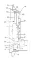
图4是图3中的轴流式风扇罩的侧视图;Fig. 4 is a side view of the axial flow fan cover in Fig. 3;
图5是根据本发明的导向叶片的放大视图;Figure 5 is an enlarged view of a guide vane according to the present invention;
图6表示在与根据本发明的罩的中心轴线间隔开的点处的速度分量;Figure 6 represents the velocity components at a point spaced from the central axis of the shroud according to the invention;
图7表示沿着与图5的轴线A.L垂直的方向从后面看时导向叶片的气流结构;Fig. 7 shows the air flow structure of the guide vane when viewed from behind along the direction perpendicular to the axis A.L of Fig. 5;
图8是表示沿着图5中的线I-I剖取的导向叶片的示意性平面剖视图;Fig. 8 is a schematic plan sectional view showing the guide vane taken along line I-I in Fig. 5;
图9是表示沿着图5中的线II-II剖取的导向叶片的示意性平面剖视图;以及Fig. 9 is a schematic plan sectional view showing the guide vane taken along line II-II in Fig. 5; and
图10是一曲线图,用于将关于本发明的导向叶片半径比r/R的入射角和投射角的设计因素与现有技术的设计因素进行比较。Fig. 10 is a graph for comparing the design factors of the incident angle and the projection angle with respect to the guide vane radius ratio r/R of the present invention with those of the prior art.
具体实施方式Detailed ways
下面将参照附图详细地描述本发明的优选实施例。Preferred embodiments of the present invention will be described in detail below with reference to the accompanying drawings.
相同或相似的部件用与现有技术中相同或相似的附图标记表示,并且省略对其的重复描述。The same or similar components are denoted by the same or similar reference numerals as those in the prior art, and repeated descriptions thereof are omitted.
图3和图4表示本发明的轴流式风扇罩组件,其中轴流式风扇10和罩30被装配成一整体单元。Figures 3 and 4 illustrate the axial fan housing assembly of the present invention wherein the
轴流式风扇10包括环形风扇毂11、和沿着该风扇毂11的外周以预定间隔布置的多个叶片12。罩30包括电机支撑环32、导向叶片35和壳体31。The
如图4所示,轴流式风扇10一体地设有风扇带(fan band)13,该风扇带与风扇毂11同轴。风扇带13固定地连接各叶片12的端部,以抑制叶片12端部处的涡流,从而提高吹风效率。轴流式风扇10通常由合成树脂制成为整体形式,但可选的是,其可以由轻质铝等模制而成。As shown in FIG. 4 , the
同时,轴流式风扇10的风扇带13的前端膨胀成喇叭口形,并且从罩30的壳体31的后端到上游延伸成U形构造,从而形成空气引入部分13a以包围空气引导部分31b的前端。At the same time, the front end of the
在罩30的壳体31中,其前部为矩形形状以横跨热交换器的整个后部,并且周边部分伸出预定高度以确保热交换器后部之间的气流空间。壳体31朝向下游减少,以形成环形通风孔31a,并具有成形为喇叭口的侧部,该侧部朝向上游变宽而朝向下游减少。In the
电机支撑环32布置在壳体31的通风孔31a的中央,从而使轴流式风扇10与电机20固定在一起。电机支撑环32具有与轴流式风扇10的风扇毂11和电机20一样的环形形状。The
如图3所示,导向叶片35径向布置在电机支撑环32和壳体31之间,以相对于壳体31将电机支撑环32固定地支撑在通风孔31a的中央,并且将从轴流式风扇10吹来的三维空气引入到一维方向,从而提高轴流式风扇10的吹风效率并且抑制吹风噪音。As shown in FIG. 3 , the
图5表示导向叶片35的详细结构。每个导向叶片35都形成具有预定区域的弧形,该区域由布置在前端用于引入空气的前缘37、从前缘37向下游延伸的气流引导面38和布置在气流引导面38后端的后缘39限定。由于该弧形弯曲且相对于轴向倾斜,因此由轴流式风扇10吹来的空气可被有效地折射并引入到气流引导面38。FIG. 5 shows a detailed structure of the
另外,本发明的各导向叶片35沿径向弯曲,从而使轴流式风扇10能够有效地接收三维空气并将其转换到轴向。In addition, each
同时,导向叶片35一体地设有辅助环36,该辅助环连接并支撑单个导向叶片35。每个导向叶片35都基于辅助环36而分成第一入口区域A、第一出口区域a、第二入口区域B和第二出口区域b。Meanwhile, the
在确定本发明的每个导向叶片35的结构之前,将分析由轴流式风扇10吹来的空气的速度,作为用于确定该结构的最重要的因素。Before determining the structure of each
图6表示在与中心间隔开的通风孔31a中的点P处的空气速度分量。由轴流式风扇吹来的空气由于轴流式风扇10的离心力而以轴向速度分量Uz、转动速度分量Uth和径向速度分量Ur流动。FIG. 6 shows the air velocity components at a point P in the
由于由轴流式风扇10吹来的空气必定具有轴向速度分量Uz、转动速度分量Uth和径向速度分量Ur,因此在点P处吹来的空气颗粒的实际速度矢量U变为轴向速度分量Uz、转动速度分量Uth和径向速度分量Ur之和,如图6所示。在空气颗粒的速度矢量U中,作为转动速度分量Uth和径向速度分量Ur之和的横向速度矢量Us,相对于与转动轴线平行的轴线以特定角度θ倾斜,其中θ=Tan-1(Us/Uz)。即,在点P处吹动的空气颗粒具有横向速度分量Us,并因此偏向轴流式风扇10的转动方向和径向。Since the air blown by the
对于上述吹来的空气颗粒的实际速度矢量U,导向叶片35优选地需要构造成:For the actual velocity vector U of the above-mentioned blown air particles, the
(1)朝向轴向引导作为转动速度分量Uth和径向速度分量Ur之和的横向速度矢量Us,以提高轴流式风扇10的吹风效率,并且(1) directing the transverse velocity vector Us as the sum of the rotational velocity component Uth and the radial velocity component Ur toward the axial direction to improve the blowing efficiency of the
(2)当空气经过导向叶片35时沿着转动方向和径向分散空气,以防止从发动机室产生的高温热回流到热交换器(例如,冷凝器)。(2) The air is dispersed in the rotational direction and the radial direction when the air passes the
为了满足上述要求,本发明按照如下方式来设计导向叶片35:根据导向叶片35的半径比r/R,接近转动轴心的部分沿横向引导作为转动速度分量Uth和径向速度分量Ur之和的横向速度矢量Us,以提高轴流式风扇10的吹风效率。在远离转动轴心的部分中,导向叶片35沿着转动方向和径向分散空气,以防止空气碰撞发动机及其引起的回流,从而提高空调系统的性能。In order to meet the above-mentioned requirements, the present invention designs the
因此,优选的是将导向叶片35分成两部分,以实现满足上述条件的导向叶片35。Therefore, it is preferable to divide the
另外,为了便于理解,当切线与导向叶片35的前缘37和后缘39接触时,将相对于轴线的相交角分别称为入射角Ain和投射角Aout。In addition, for ease of understanding, when the tangents are in contact with the leading
在第一入口区域A被限定为从导向叶片35的入射角Ain的总长度R中的根部到达半径r,并且第二入口区域B由剩余部分限定的情况下,优选地从第二入口区域B相对于轴线的入射角Ain随着接近顶端而增加。In the case where the first inlet area A is defined to reach the radius r from the root in the total length R of the angle of incidence Ain of the
在第一入口区域A中,作为半径r相对于导向叶片35的总长度R的比r/R优选地对应于大约0到0.4。在第二入口区域B中,作为半径r相对于导向叶片35的总长度R的比r/R优选地对应于大约0.4到1。In the first inlet region A, r/R as a ratio of the radius r to the overall length R of the
另外,在第一出口区域a被限定为从导向叶片35的投射角Aout的总长度R中的根部到达半径r,并且第二出口区域b由剩余部分限定的情况下,优选地从第二出口区域b相对于轴线的投射角Aout随着接近顶端而增加。In addition, in the case where the first outlet area a is defined to reach the radius r from the root in the total length R of the projection angle Aout of the
在第一出口区域a中,作为半径r相对于导向叶片35的总长度R的比r/R优选地对应于大约0到0.4。在第二出口区域b中,作为半径r相对于导向叶片35的总长度R的比r/R优选地对应于大约0.4到1。In the first outlet region a, r/R as a ratio of the radius r to the overall length R of the
根据典型的实验结果,在作为更接近轴心的第一入口区域A和第一出口区域a的直到大约的范围内,空气的吹风面积相对较窄,并且离心力较小。因而这样沿着轴向引导作为转动速度分量Uth和径向速度分量Ur之和的横向速度分量Us。在作为第二入口区域B和第二出口区域b的从的范围内,离心力随着进一步远离轴心而以更大的值作用,因此横向速度分量Us沿着转动方向和径向分散。According to typical experimental results, in the first inlet area A and the first outlet area a which are closer to the axis until about Within the range, the blowing area of the air is relatively narrow, and the centrifugal force is small. The transverse velocity component Us , which is the sum of the rotational velocity component Uth and the radial velocity component Ur , is thus directed axially. In the second entry area B and the second exit area b from In the range of , the centrifugal force acts at a greater value as it gets further away from the axis, so the transverse velocity component Us is dispersed along the rotational direction and radial direction.
图7示意性地表示在后视图或从与轴线A.L垂直的方向看时,沿着图5的线I-I剖取的导向叶片的气流结构。在该结构中,优选的是沿着轴向引导作为转动速度分量Uth和径向速度分量Ur之和的横向速度分量Us,以获得最大的效率。FIG. 7 schematically represents the airflow configuration of the guide vane taken along line II of FIG. 5 , in rear view or from a direction perpendicular to the axis AL. In this configuration, it is preferred to direct the transverse velocity component U s as the sum of the rotational velocity component Uth and the radial velocity componentU rin the axial direction to obtain maximum efficiency.
导向叶片35保持与横向速度分量Us垂直的角度,从而其L.E.L可有效地接收空气的横向流动。由于导向叶片35被弯曲成使得L.E.L在导向叶片35各点处的接触线具有横向速度分量Us的倾斜角θs,其中θs=Tan-1(Ur/Uth),因此其具有变化曲率,其中在从总体看时中心沿着轴流式风扇叶片12的转动方向弯曲。The
下面将参照平面剖视图进行讨论,在作为第一入口区域A和第一出口区域a的直到大约
图8示意性地表示沿着图5的线I-I剖取的、在从轴流式风扇中心的点P处的叶片12和导向叶片35的平面图,以更详细地理解该平面剖视图的结构。FIG. 8 schematically shows a plan view of the
导向叶片35的气流引导面38用于沿轴向折射由前缘37倾斜吹来的具有横向速度分量Us的空气。为了平行于前缘37引入吹来的空气,使入射角Ain与叶片12的引入到前缘的空气流入角Bout相同(Ain=Bout),该投射角为引入到前缘的吹来空气的引入角。将投射角Aout设计为0°或与轴线A.L平行,从而使空气沿着轴向吹来。气流引导面38以弧形形式弯曲,以连接在前缘37和后缘39之间。The
即,该气流引导面38被如此弯曲,以使得在第一入口区域A中入射角Ain变成与空气流入角Tan-1(Us/Uz)相同,并且在第一出口区域a中投射角Aout相对于轴线变成0°。That is, the
因此,在沿着线I-I剖取的导向叶片35的前缘37中,在与轴心间隔开的点P处,由轴流式风扇10吹来的空气沿着以引入到前缘的空气流入角Bout(Tan-1(Us/Uz))倾斜的方向引入,该投射角由速度矢量U(即,横向速度分量Us和轴向速度分量Uz的合成矢量)和轴线A.L限定。对应于引入到前缘的空气流入角Bout,导向叶片35的前缘37相对于轴线以入射角Ain倾斜设置,而后缘39平行于轴线设置。Therefore, in the leading
前缘37和后缘39之间的气流引导面38的半径与一圆相同,该圆具有在由前缘37和后缘39的法线相交的点q处的圆心、和长度为从点q到前缘37或后缘39的半径。该圆弧的曲率使空气的涡流最小,以更平稳地沿着气流引导面38折射空气流,并沿轴向吹来该空气。The radius of the
如上所述,在作为更接近受离心力影响较小的轴心的第一入口区域A和第一出口区域a的直到大约
由于由导向叶片35除去了转动速度分量Uth和径向速度分量Ur,因此由轴流式风扇10吹来的空气沿轴向平稳地吹来,这样提高了空气的轴向流速,从而显著地提高了轴流式风扇10的吹风效率。Since the rotational velocity component Uth and the radial velocity component Ur are removed by the
具体地,在安装于冷凝器的前方的推进式轴流式风扇10的情况下,吹来的空气在热交换器的散热片周围具有较高的透射比,从而进一步提高了吹风效率。Specifically, in the case of the propulsive
现在将对在作为第二入口区域B和第二出口区域b的从
当沿着图5中的线II-II剖取时,必须沿轴向引导作为转动速度分量Uth和径向速度分量Ur之和的大部分的横向速度分量Us,并且沿着转动方向和径向分散该横向速度分量Us。When taken along the line II-II in Fig. 5, the majority of the transverse velocity component Us , which is the sum of the rotational velocity component Uth and the radial velocity component Ur , must be directed axially, and in the rotational direction and radially disperse the transverse velocity component Us .
当然,导向叶片35具有变化曲率结构,其中当沿轴向看时,中心沿着轴流式风扇叶片12的转动方向弯曲,除了在俯视图中所看的结构之外,与沿轴向看时沿线I-I剖取所示的大致相同。Of course, the
因此,将参照平面剖视图进行讨论,在从大约
图9是表示沿着图5中的线II-II剖取的、在从轴流式风扇10的中心的点P处的叶片12和导向叶片35的示意性平面剖视图,以说明上述平面剖视图的结构。9 is a schematic plan sectional view showing the
导向叶片35的气流引导面38用于沿轴向折射沿外周方向倾斜引入的、具有横向速度分量Us的空气,从而该空气以一略大于平行角度的角度引入到前缘37。在这种情况下,使Ain(θ′)大于Bout(θ),其中θ′>θ。入射角Ain形成得大于通过叶片12的空气的引入到前缘的空气流入角Bout(即,被引入到前缘37的空气流入角)。投射角Aout形成为角度θ,从而吹来的空气具有横向分量。即,投射角Aout形成为具有相对于轴线A.L倾斜的倾角。The airflow guide surfaces 38 of the
导向叶片35弯曲成在前缘37和后缘39之间的大曲率的弧形。The guide vanes 35 are curved in an arc of high curvature between a
因此,在沿着线II-II剖取的导向叶片35的前缘37中,在与轴心间隔开的点P处,由轴流式风扇10吹来的空气沿着以引入到前缘的空气流入角Bout(Tan-1(Us/Uz))倾斜的方向引入,该投射角由速度矢量U(即,横向速度分量Us和轴向速度分量Uz的合成矢量)和轴线A.L限定。对应于引入到前缘的空气流入角Bout,导向叶片35的前缘37相对于轴线以入射角Ain(θ′)倾斜设置,而后缘39平行于轴线设置。Therefore, in the leading
前缘37和后缘39之间的气流引导面38的半径与一圆相同,该圆具有在由前缘37和后缘39的法线相交的点q处的圆心和长度为从点q到前缘37或后缘39的半径。该圆弧的曲率在附近具有较小曲率,但是随着接近顶端而增加直到大致无限值。The
图10是一曲线图,用于将关于本发明的导向叶片半径比r/R的入射角和投射角的设计因素与现有技术的设计因素进行比较。Fig. 10 is a graph for comparing the design factors of the incident angle and the projection angle with respect to the guide vane radius ratio r/R of the present invention with those of the prior art.
如图10所示,现有技术的投射角Aout保持0°以与轴线平行。然而,明显的是,本发明的投射角Aout直到在导向叶片35的第二出口区域b中的半径比r/R为0.4到1时,相对于轴线从大约0°到60°逐渐增加。As shown in Fig. 10, the projection angle Aout of the prior art is kept at 0° to be parallel to the axis. However, it is evident that the inventive projection angle Aout increases gradually from about 0° to 60° relative to the axis up to a radius ratio r/R of 0.4 to 1 in the second outlet region b of the
还看到的是,现有技术的入射角Ain直到导向叶片的半径比r/R为0.5到1时相对于轴线逐渐增加,从而在顶端具有大约60°。然而,本发明的入射角Ain直到导向叶片35的第二入口区域B中的半径比r/R为0.4到1时,相对于轴线比现有技术中更急剧地逐渐增加,从而在半径比r/R大致为1的顶端处达到大致90°。It is also seen that the angle of incidence Ain of the prior art gradually increases with respect to the axis until the radius ratio r/R of the guide vanes is 0.5 to 1, so as to have approximately 60° at the tip. However, the angle of incidence Ain of the invention increases gradually with respect to the axis more sharply than in the prior art up to a radius ratio r/R of 0.4 to 1 in the second inlet region B of the
在对应于
如上所述,与半径比r/R的增加成比例的是,在其中离心力的影响随着更远离轴心而变得更大的r/R>0.4到
因此,在由轴流式风扇10吹来的空气中,在附近,与前缘37平行地引入空气的同时,轴向流动分量逐渐减少而横向分量逐渐增加,从而平稳地沿着气流引导面38轴向地折射空气。随着接近顶端,大部分空气沿着转动方向和径向如分散一样流动,从而空气可绕过在轴流式风扇10后部中的发动机流动,而不会碰撞发动机,由此防止由发动机产生的高温热回流到热交换器。Therefore, in the air blown by the
如上所述,尽管在本发明中已经描述了导向叶片35与电机支撑环32和壳体31一体地形成,但是本发明并不限于此,而是可分开制造导向叶片35,然后另外地与电机支撑环32和壳体31接合。As described above, although it has been described in the present invention that the
工业实用性Industrial Applicability
如上所述,本发明的罩的导向叶片设计成直到半径比r/R为0.4到1入射角和投射角才逐渐增加,从而提高了吹风效率,同时防止了由发动机产生的高温热回流到热交换器,从而提高了空调系统的性能。As mentioned above, the guide vanes of the shroud of the present invention are designed to gradually increase until the radius ratio r/R is 0.4 to 1. exchanger, thereby improving the performance of the air conditioning system.
Claims (7)
Translated fromChineseApplications Claiming Priority (2)
| Application Number | Priority Date | Filing Date | Title |
|---|---|---|---|
| KR1020030044222 | 2003-07-01 | ||
| KR1020030044222AKR100937929B1 (en) | 2003-07-01 | 2003-07-01 | Axial Fan Shroud Stator |
Publications (2)
| Publication Number | Publication Date |
|---|---|
| CN1813135A CN1813135A (en) | 2006-08-02 |
| CN100476216Ctrue CN100476216C (en) | 2009-04-08 |
Family
ID=36640593
Family Applications (1)
| Application Number | Title | Priority Date | Filing Date |
|---|---|---|---|
| CNB2004800185089AExpired - LifetimeCN100476216C (en) | 2003-07-01 | 2004-07-01 | Guide blade of axial flow fan cover |
Country Status (4)
| Country | Link |
|---|---|
| US (1) | US7220102B2 (en) |
| KR (1) | KR100937929B1 (en) |
| CN (1) | CN100476216C (en) |
| WO (1) | WO2005003569A1 (en) |
Families Citing this family (49)
| Publication number | Priority date | Publication date | Assignee | Title |
|---|---|---|---|---|
| EP1600640A3 (en)* | 2004-04-26 | 2009-11-04 | Behr GmbH & Co. KG | Fan shroud for a heat exchanger, in particular for vehicles. |
| TWI282392B (en)* | 2005-08-04 | 2007-06-11 | Delta Electronics Inc | Passive fan assembly |
| FR2890569B1 (en) | 2005-09-09 | 2007-11-16 | Groupe Leader Sa Sa | FAN FOR FIRE FIGHTING INCLUDING AIR FLOW RECTIFIER |
| JP4808482B2 (en) | 2005-11-30 | 2011-11-02 | 山洋電気株式会社 | Axial blower |
| JP4664196B2 (en)* | 2005-11-30 | 2011-04-06 | 山洋電気株式会社 | Axial blower |
| US20080078340A1 (en)* | 2006-09-28 | 2008-04-03 | Siemens Vdo Automotive Canada Inc. | Fan Module motor mont arms with shape optimization |
| WO2008031192A1 (en)* | 2006-09-12 | 2008-03-20 | Continental Automotive Canada, Inc. | Fan module motor mount arms with shape optimization |
| EP1939456B1 (en)* | 2006-12-27 | 2014-03-12 | Pfannenberg GmbH | Air passage device |
| JP2008261280A (en)* | 2007-04-12 | 2008-10-30 | Nippon Densan Corp | Axial fan |
| TWI395539B (en)* | 2007-05-25 | 2013-05-01 | Delta Electronics Inc | Fan and frame thereof |
| US20120121410A1 (en)* | 2010-11-11 | 2012-05-17 | Wen-Hao Liu | Round axial fan with balancing structure |
| US20120315134A1 (en)* | 2011-06-13 | 2012-12-13 | Asia Vital Components Co., Ltd. | Fan impeller structure |
| CN102996473B (en)* | 2011-09-15 | 2017-05-10 | 富瑞精密组件(昆山)有限公司 | Fan |
| FR2989999B1 (en) | 2012-04-26 | 2016-01-01 | Sdmo Ind | COOLING DEVICE COMPRISING AN AXIAL FAN WITH CENTRAL FLOW RECTIFICATION AND CORRESPONDING ELECTROGEN GROUP. |
| EP2878892B1 (en)* | 2012-07-03 | 2019-09-18 | Mitsubishi Electric Corporation | Indoor unit for air conditioner, and air conditioner with indoor unit |
| CN102758802B (en)* | 2012-07-18 | 2016-12-21 | Tcl空调器(中山)有限公司 | Protective cover, fan component and air-conditioner outdoor unit |
| DE102012109542A1 (en)* | 2012-10-08 | 2014-04-10 | Ebm-Papst Mulfingen Gmbh & Co. Kg | "Flow straightener for an axial fan" |
| US9618010B2 (en) | 2013-04-22 | 2017-04-11 | Lennox Industries Inc. | Fan systems |
| FR3008132B1 (en)* | 2013-07-04 | 2017-07-14 | Valeo Systemes Thermiques | AUTOMOTIVE FAN NOZZLE WITH DOUBLE-WALL ARMS |
| AU2013393876B2 (en)* | 2013-07-12 | 2017-12-14 | Volvo Truck Corporation | Heat exchanger system for a vehicle |
| US9593885B2 (en) | 2013-08-30 | 2017-03-14 | Advanced Analytical Solutions, Llc | Axial fan inlet wind-turning vane assembly |
| EP2886872A1 (en)* | 2013-12-17 | 2015-06-24 | Delphi Automotive Systems Luxembourg SA | Engine fan |
| CN104374209A (en)* | 2014-05-29 | 2015-02-25 | 山西太钢不锈钢股份有限公司 | Method for recovering sintering waste heat by using fan and rear guide vane of the fan |
| US10174481B2 (en)* | 2014-08-26 | 2019-01-08 | Cnh Industrial America Llc | Shroud wear ring for a work vehicle |
| JP2017053295A (en)* | 2015-09-11 | 2017-03-16 | 三星電子株式会社Samsung Electronics Co.,Ltd. | Blower and outdoor unit |
| CN108603512B (en) | 2016-02-08 | 2021-03-12 | 罗伯特·博世有限公司 | Engine cooling fan shroud with unplugged outlets |
| KR101798574B1 (en)* | 2016-05-02 | 2017-11-17 | 동부대우전자 주식회사 | Radiation blower and refrigerator comprising the same |
| WO2017192651A1 (en) | 2016-05-03 | 2017-11-09 | Carrier Corporation | Vane axial fan with intermediate flow control rings |
| US10364021B2 (en)* | 2016-09-26 | 2019-07-30 | General Electric Company | Aircraft having an aft engine and stabilizer root fillet |
| DE102017209291A1 (en)* | 2017-06-01 | 2018-12-06 | Ziehl-Abegg Se | Fan and guide grille for a fan |
| DE102017126823A1 (en)* | 2017-11-15 | 2019-05-16 | Brose Fahrzeugteile GmbH & Co. Kommanditgesellschaft, Würzburg | Cooling fan module |
| DE102018110618A1 (en)* | 2018-05-03 | 2019-11-07 | Ebm-Papst Mulfingen Gmbh & Co. Kg | Holding device for anemometer and radial fan |
| DE102018128811A1 (en)* | 2018-11-16 | 2020-05-20 | Ebm-Papst Mulfingen Gmbh & Co. Kg | Diagonal fan that can be combined with different nozzles |
| KR102829014B1 (en)* | 2019-10-28 | 2025-07-04 | 삼성전자주식회사 | Diffuser, diffuser assembly, and air conditioner having the same |
| USD938010S1 (en) | 2019-12-10 | 2021-12-07 | Regal Beloit America, Inc. | Fan hub |
| US11859634B2 (en) | 2019-12-10 | 2024-01-02 | Regal Beloit America, Inc. | Fan hub configuration for an electric motor assembly |
| USD938009S1 (en) | 2019-12-10 | 2021-12-07 | Regal Beloit America, Inc. | Fan hub |
| US11555508B2 (en)* | 2019-12-10 | 2023-01-17 | Regal Beloit America, Inc. | Fan shroud for an electric motor assembly |
| USD938011S1 (en) | 2019-12-10 | 2021-12-07 | Regal Beloit America, Inc. | Fan blade |
| US11371517B2 (en) | 2019-12-10 | 2022-06-28 | Regal Beloit America, Inc. | Hub inlet surface for an electric motor assembly |
| CA3180967A1 (en)* | 2020-04-23 | 2021-10-28 | Clark Equipment Company | Identification and reduction of backflow suction in cooling systems |
| KR102805334B1 (en)* | 2020-06-10 | 2025-05-13 | 디와이오토 주식회사 | Cooling fan shroud provided with airfoil stator structure |
| CN112963366B (en)* | 2021-01-12 | 2024-12-27 | 江西农业大学 | Angle-adjustable blades and fans |
| JP7522674B2 (en)* | 2021-02-03 | 2024-07-25 | 株式会社ミツバ | Fan shroud and blower |
| CN113154112A (en)* | 2021-04-27 | 2021-07-23 | 博纳斯威阀门股份有限公司 | Hydraulic self-generating intelligent regulating valve |
| DE102021205489A1 (en)* | 2021-05-31 | 2022-12-01 | Robert Bosch Gesellschaft mit beschränkter Haftung | Fan mount and heat pump heat transfer unit with a fan mount |
| IT202100020606A1 (en)* | 2021-07-30 | 2023-01-30 | Johnson Electric Asti S R L | Cooling fan module for a vehicle |
| CN116691893A (en)* | 2022-02-28 | 2023-09-05 | 浙江春风动力股份有限公司 | motorcycle |
| KR20250001796A (en)* | 2023-06-29 | 2025-01-07 | 삼성전자주식회사 | Outdoor unit for air conditioner |
Citations (2)
| Publication number | Priority date | Publication date | Assignee | Title |
|---|---|---|---|---|
| US4548548A (en)* | 1984-05-23 | 1985-10-22 | Airflow Research And Manufacturing Corp. | Fan and housing |
| US6398492B1 (en)* | 1998-12-31 | 2002-06-04 | Halla Climate Control Corp. | Airflow guide stator vane for axial flow fan and shrouded axial flow fan assembly having such airflow guide stator vanes |
Family Cites Families (7)
| Publication number | Priority date | Publication date | Assignee | Title |
|---|---|---|---|---|
| US2154313A (en)* | 1938-04-01 | 1939-04-11 | Gen Electric | Directing vane |
| US4927324A (en)* | 1989-01-09 | 1990-05-22 | Vornado Air Circulation Systems, Inc. | Ducted fan |
| JPH02196197A (en)* | 1989-01-25 | 1990-08-02 | Daikin Ind Ltd | Axial blower |
| KR950008058B1 (en)* | 1992-07-24 | 1995-07-24 | 한라공조주식회사 | Fan and shroud assembly |
| JPH10205497A (en)* | 1996-11-21 | 1998-08-04 | Zexel Corp | Cooling air introducing/discharging device |
| US6142733A (en)* | 1998-12-30 | 2000-11-07 | Valeo Thermique Moteur | Stator for fan |
| JP4442029B2 (en)* | 2000-12-15 | 2010-03-31 | パナソニック株式会社 | Blower |
- 2003
- 2003-07-01KRKR1020030044222Apatent/KR100937929B1/ennot_activeExpired - Fee Related
- 2004
- 2004-07-01USUS10/561,730patent/US7220102B2/ennot_activeExpired - Lifetime
- 2004-07-01WOPCT/KR2004/001610patent/WO2005003569A1/enactiveApplication Filing
- 2004-07-01CNCNB2004800185089Apatent/CN100476216C/ennot_activeExpired - Lifetime
Patent Citations (2)
| Publication number | Priority date | Publication date | Assignee | Title |
|---|---|---|---|---|
| US4548548A (en)* | 1984-05-23 | 1985-10-22 | Airflow Research And Manufacturing Corp. | Fan and housing |
| US6398492B1 (en)* | 1998-12-31 | 2002-06-04 | Halla Climate Control Corp. | Airflow guide stator vane for axial flow fan and shrouded axial flow fan assembly having such airflow guide stator vanes |
Also Published As
| Publication number | Publication date |
|---|---|
| KR20050005086A (en) | 2005-01-13 |
| KR100937929B1 (en) | 2010-01-21 |
| US20060147304A1 (en) | 2006-07-06 |
| CN1813135A (en) | 2006-08-02 |
| US7220102B2 (en) | 2007-05-22 |
| WO2005003569A1 (en) | 2005-01-13 |
Similar Documents
| Publication | Publication Date | Title |
|---|---|---|
| CN100476216C (en) | Guide blade of axial flow fan cover | |
| JP3385336B2 (en) | Guide vane for axial fan and axial fan shroud assembly including the guide vane | |
| JP3928083B2 (en) | Fan and shroud assembly | |
| KR101019832B1 (en) | Centrifugal blower | |
| US7500825B2 (en) | Centrifugal blower | |
| US6579063B2 (en) | High efficiency, inflow-adapted, axial-flow fan | |
| KR101018146B1 (en) | Axial fan assembly | |
| US8011891B2 (en) | Centrifugal multiblade fan | |
| US9909485B2 (en) | Cooling fan module and system | |
| US7121807B2 (en) | Axial-flow fan | |
| US20100189557A1 (en) | Impeller and fan | |
| JP2001271790A (en) | Centrifugal impeller and air purifier | |
| JP2004218450A (en) | Centrifugal blower | |
| US7771169B2 (en) | Centrifugal multiblade fan | |
| JP2011099409A (en) | Blower and heat pump device | |
| JP2000009083A (en) | Impeller | |
| CN222436671U (en) | A centrifugal fan | |
| US12078187B2 (en) | Impeller, fan, and air-conditioning apparatus | |
| JP2001165093A (en) | Air blower | |
| JPH04279800A (en) | Push-in type axial flow fan |
Legal Events
| Date | Code | Title | Description |
|---|---|---|---|
| C06 | Publication | ||
| PB01 | Publication | ||
| C10 | Entry into substantive examination | ||
| SE01 | Entry into force of request for substantive examination | ||
| C14 | Grant of patent or utility model | ||
| GR01 | Patent grant | ||
| C56 | Change in the name or address of the patentee | Owner name:HALLA VISTEON CLIMATE CONTROL CORP. Free format text:FORMER NAME: HANNA AIR CONDITIONER CO. LTD. | |
| CP01 | Change in the name or title of a patent holder | Address after:South Korea field wide area Patentee after:Halla Visteon Climate Control (Shanghai) Technology Co.,Ltd. Address before:South Korea field wide area Patentee before:HALLA CLIMATE CONTROL Corp. | |
| C56 | Change in the name or address of the patentee | ||
| CP01 | Change in the name or title of a patent holder | Address after:South Korea field wide area Patentee after:HANON SYSTEMS Address before:South Korea field wide area Patentee before:Halla Visteon Climate Control (Shanghai) Technology Co.,Ltd. | |
| CP01 | Change in the name or title of a patent holder | ||
| CP01 | Change in the name or title of a patent holder | Address after:South Korea field wide area Patentee after:HANON SYSTEMS Address before:South Korea field wide area Patentee before:HANON SYSTEMS | |
| CX01 | Expiry of patent term | ||
| CX01 | Expiry of patent term | Granted publication date:20090408 |