CN100474058C - Reflective and transflective liquid crystal display using a wire grid polarizer and manufacturing method thereof - Google Patents
Reflective and transflective liquid crystal display using a wire grid polarizer and manufacturing method thereofDownload PDFInfo
- Publication number
- CN100474058C CN100474058CCNB038149990ACN03814999ACN100474058CCN 100474058 CCN100474058 CCN 100474058CCN B038149990 ACNB038149990 ACN B038149990ACN 03814999 ACN03814999 ACN 03814999ACN 100474058 CCN100474058 CCN 100474058C
- Authority
- CN
- China
- Prior art keywords
- equipment
- gap
- lcd
- cell
- reflective
- Prior art date
- Legal status (The legal status is an assumption and is not a legal conclusion. Google has not performed a legal analysis and makes no representation as to the accuracy of the status listed.)
- Expired - Fee Related
Links
Images


Classifications
- G—PHYSICS
- G02—OPTICS
- G02F—OPTICAL DEVICES OR ARRANGEMENTS FOR THE CONTROL OF LIGHT BY MODIFICATION OF THE OPTICAL PROPERTIES OF THE MEDIA OF THE ELEMENTS INVOLVED THEREIN; NON-LINEAR OPTICS; FREQUENCY-CHANGING OF LIGHT; OPTICAL LOGIC ELEMENTS; OPTICAL ANALOGUE/DIGITAL CONVERTERS
- G02F1/00—Devices or arrangements for the control of the intensity, colour, phase, polarisation or direction of light arriving from an independent light source, e.g. switching, gating or modulating; Non-linear optics
- G02F1/01—Devices or arrangements for the control of the intensity, colour, phase, polarisation or direction of light arriving from an independent light source, e.g. switching, gating or modulating; Non-linear optics for the control of the intensity, phase, polarisation or colour
- G02F1/13—Devices or arrangements for the control of the intensity, colour, phase, polarisation or direction of light arriving from an independent light source, e.g. switching, gating or modulating; Non-linear optics for the control of the intensity, phase, polarisation or colour based on liquid crystals, e.g. single liquid crystal display cells
- G02F1/133—Constructional arrangements; Operation of liquid crystal cells; Circuit arrangements
- G02F1/1333—Constructional arrangements; Manufacturing methods
- G02F1/1335—Structural association of cells with optical devices, e.g. polarisers or reflectors
- G02F1/133553—Reflecting elements
- G02F1/133555—Transflectors
- G—PHYSICS
- G02—OPTICS
- G02F—OPTICAL DEVICES OR ARRANGEMENTS FOR THE CONTROL OF LIGHT BY MODIFICATION OF THE OPTICAL PROPERTIES OF THE MEDIA OF THE ELEMENTS INVOLVED THEREIN; NON-LINEAR OPTICS; FREQUENCY-CHANGING OF LIGHT; OPTICAL LOGIC ELEMENTS; OPTICAL ANALOGUE/DIGITAL CONVERTERS
- G02F1/00—Devices or arrangements for the control of the intensity, colour, phase, polarisation or direction of light arriving from an independent light source, e.g. switching, gating or modulating; Non-linear optics
- G02F1/01—Devices or arrangements for the control of the intensity, colour, phase, polarisation or direction of light arriving from an independent light source, e.g. switching, gating or modulating; Non-linear optics for the control of the intensity, phase, polarisation or colour
- G02F1/13—Devices or arrangements for the control of the intensity, colour, phase, polarisation or direction of light arriving from an independent light source, e.g. switching, gating or modulating; Non-linear optics for the control of the intensity, phase, polarisation or colour based on liquid crystals, e.g. single liquid crystal display cells
- G02F1/133—Constructional arrangements; Operation of liquid crystal cells; Circuit arrangements
- G02F1/1333—Constructional arrangements; Manufacturing methods
- G02F1/1335—Structural association of cells with optical devices, e.g. polarisers or reflectors
- G02F1/133528—Polarisers
- G02F1/133536—Reflective polarizers
- G—PHYSICS
- G02—OPTICS
- G02F—OPTICAL DEVICES OR ARRANGEMENTS FOR THE CONTROL OF LIGHT BY MODIFICATION OF THE OPTICAL PROPERTIES OF THE MEDIA OF THE ELEMENTS INVOLVED THEREIN; NON-LINEAR OPTICS; FREQUENCY-CHANGING OF LIGHT; OPTICAL LOGIC ELEMENTS; OPTICAL ANALOGUE/DIGITAL CONVERTERS
- G02F1/00—Devices or arrangements for the control of the intensity, colour, phase, polarisation or direction of light arriving from an independent light source, e.g. switching, gating or modulating; Non-linear optics
- G02F1/01—Devices or arrangements for the control of the intensity, colour, phase, polarisation or direction of light arriving from an independent light source, e.g. switching, gating or modulating; Non-linear optics for the control of the intensity, phase, polarisation or colour
- G02F1/13—Devices or arrangements for the control of the intensity, colour, phase, polarisation or direction of light arriving from an independent light source, e.g. switching, gating or modulating; Non-linear optics for the control of the intensity, phase, polarisation or colour based on liquid crystals, e.g. single liquid crystal display cells
- G02F1/133—Constructional arrangements; Operation of liquid crystal cells; Circuit arrangements
- G02F1/1333—Constructional arrangements; Manufacturing methods
- G02F1/1335—Structural association of cells with optical devices, e.g. polarisers or reflectors
- G02F1/133528—Polarisers
- G02F1/133543—Cholesteric polarisers
- G—PHYSICS
- G02—OPTICS
- G02F—OPTICAL DEVICES OR ARRANGEMENTS FOR THE CONTROL OF LIGHT BY MODIFICATION OF THE OPTICAL PROPERTIES OF THE MEDIA OF THE ELEMENTS INVOLVED THEREIN; NON-LINEAR OPTICS; FREQUENCY-CHANGING OF LIGHT; OPTICAL LOGIC ELEMENTS; OPTICAL ANALOGUE/DIGITAL CONVERTERS
- G02F1/00—Devices or arrangements for the control of the intensity, colour, phase, polarisation or direction of light arriving from an independent light source, e.g. switching, gating or modulating; Non-linear optics
- G02F1/01—Devices or arrangements for the control of the intensity, colour, phase, polarisation or direction of light arriving from an independent light source, e.g. switching, gating or modulating; Non-linear optics for the control of the intensity, phase, polarisation or colour
- G02F1/13—Devices or arrangements for the control of the intensity, colour, phase, polarisation or direction of light arriving from an independent light source, e.g. switching, gating or modulating; Non-linear optics for the control of the intensity, phase, polarisation or colour based on liquid crystals, e.g. single liquid crystal display cells
- G02F1/133—Constructional arrangements; Operation of liquid crystal cells; Circuit arrangements
- G02F1/1333—Constructional arrangements; Manufacturing methods
- G02F1/1335—Structural association of cells with optical devices, e.g. polarisers or reflectors
- G02F1/13356—Structural association of cells with optical devices, e.g. polarisers or reflectors characterised by the placement of the optical elements
- G02F1/133565—Structural association of cells with optical devices, e.g. polarisers or reflectors characterised by the placement of the optical elements inside the LC elements, i.e. between the cell substrates
Landscapes
- Physics & Mathematics (AREA)
- Nonlinear Science (AREA)
- Mathematical Physics (AREA)
- Chemical & Material Sciences (AREA)
- Crystallography & Structural Chemistry (AREA)
- General Physics & Mathematics (AREA)
- Optics & Photonics (AREA)
- Liquid Crystal (AREA)
Abstract
Translated fromChineseDescription
Translated fromChinese技术领域technical field
本发明涉及发射型液晶显示器,尤其涉及使用埋式线栅偏振器(WGP)作为环境光偏振相关反射器的方法与设备,并要求2002年5月6日提交的美国临时申请号为60/378,862的优先权利益。This invention relates to emissive liquid crystal displays, and more particularly to methods and apparatus using buried wire grid polarizers (WGPs) as polarization dependent reflectors for ambient light, and claims U.S. Provisional Application No. 60/378,862 filed May 6, 2002 priority interests.
背景技术Background technique
发射型液晶显示器(LCD)呈现出高反差比与良好的色饱和度,但因要求背光而功耗高。在明亮的环境下,显示被阳光冲掉。另一方面,反射型LCD显示信息内容要依靠环境光,因其不要背光,故明显减小了功耗,但其反差比一般较低,而且色饱和度比发射型差得多,在黑暗环境中,反射型LCD几乎没有能见度。Emissive liquid crystal displays (LCDs) exhibit high contrast ratios and good color saturation, but require high power consumption due to backlight requirements. In bright environments, the display is washed out by sunlight. On the other hand, reflective LCD display information content depends on ambient light, because it does not need backlight, so the power consumption is significantly reduced, but its contrast ratio is generally lower, and the color saturation is much worse than that of the emissive type. Among them, the reflective LCD has almost no visibility.
夏普(Sharp)提出了贯通型(transflective)LCD(美国专利6,281,952B1;6,295,109B1;6,330,047B1),各像素分成R(反射型)与T(透射型)子像素,R与T的面积比通常为4:1,有利于反射显示。透射显示只用于暗环境,旨在节能。Sharp (Sharp) proposed a transflective LCD (US patent 6,281,952B1; 6,295,109B1; 6,330,047B1), each pixel is divided into R (reflective) and T (transmissive) sub-pixels, and the area ratio of R and T is usually 4:1, which is good for reflective display. Transmissive displays are only used in dark environments to save energy.
已知的两种基本贯通型LCD是单晶胞隙(single cell gap)(见图1a)和双晶胞隙(double cell gap)(见图1b)。The two basic known through-type LCDs are the single cell gap (see Figure 1a) and the double cell gap (see Figure 1b).
后面揭示的美国专利局针对本发明内容所作的最新研究,发布了下述8件美国专利:The U.S. Patent Office disclosed later released the following 8 U.S. patents for the latest research done on the content of the present invention:
授与西米祖(Shimizu)等人的美国专利6,341,002,描述了在贯通型LCD中获取同等发光效率与反差比的双晶胞隙方法。T像素的晶胞隙为R像素的两倍大,要求两块相位补偿膜;US Patent 6,341,002 to Shimizu et al. describes a dual cell gap approach to achieve equivalent luminous efficiency and contrast ratio in a pass-through LCD. The cell gap of the T pixel is twice as large as that of the R pixel, requiring two phase compensation films;
授与汉森(Hansen)等人的美国专利6,108,131,揭示了把非偏振光转换成线性偏振光的技术,涉及到投影显示光源,但不涉及显示器本身;US Patent 6,108,131 to Hansen et al. discloses techniques for converting unpolarized light into linearly polarized light, involving projection display light sources but not the displays themselves;
授与汉森等人的美国专利5,986,730,描述了用于其中使用线栅偏振器的反射与透射两种器件的显示器结构,其中的反射与透射显示器共享同样的像素,覆盖着整个像素;US Patent 5,986,730 to Hansen et al. describes a display structure for both reflective and transmissive devices in which wire grid polarizers are used, where the reflective and transmissive displays share the same pixel, covering the entire pixel;
授与格林贝格(Grinberg)等人的美国专利4,688,897,同样描述了把线栅偏振器用作反射型显示器的反射器的显示设备;U.S. Patent 4,688,897 to Grinberg et al. also describes a display device using a wire grid polarizer as a reflector for a reflective display;
授与鲁(Lu)等人的美国专利5,764,324,描述了用功能与反射电极(第二基片)一样的导电透明电极(第一基片)减少图像保留的反射型显示器;U.S. Patent 5,764,324 to Lu et al. describes a reflective display with reduced image retention using a conductive transparent electrode (first substrate) that functions as the reflective electrode (second substrate);
授与奥基莫土(Okimoto)等人的美国专利6,281,952B1,描述了对发射与反射像素应用两个晶胞隙的贯通型LCD;US Patent 6,281,952B1 to Okimoto et al. describes a feed-through LCD using two cell gaps for emissive and reflective pixels;
授与库伯(Kubo)等人的美国专利6,295,109B1,描述了有两块相位迟后膜的LCD;和US Patent 6,295,109B1 to Kubo et al. describes an LCD with two retardation films; and
授与库伯等人的美国专利6,330,047B1,揭示了在两基片间设置了LC层的LCD设备,一块基片有透射电极,另一块基片有反射电极区,透射电极与各像素区对应。US Patent 6,330,047B1 to Cooper et al. discloses an LCD device with an LC layer disposed between two substrates, one substrate having a transmissive electrode and the other substrate having a reflective electrode area, the transmissive electrode corresponding to each pixel area.
为了更好地理解原有技术,可参照图1a与1b,图1a示出原有技术应用单晶胞隙的贯通型LCD视图,图1b示出原有技术应用双晶胞隙的贯通型LCD图。单晶胞隙法对R与T两种模式都应用相同的晶胞隙(d),该晶胞隙对R模式操作优化,因光只通过LC层一次,故T模式的透光率低于50%。在双晶胞隙法中,R与T子像素的晶胞隙分别为d与2d。在此方法中,R与T都能得到高发光效率,但T模式的响应时间比R模式的响应时间长四倍。上述诸法的共同问题是R与T像素的色饱和度不同,对R像素,环境光通过滤色器两次,但对T像素,背光只通过滤色器一次,故它们的色饱和度不同。In order to better understand the prior art, please refer to Figures 1a and 1b. Figure 1a shows a view of a through-type LCD using a single-crystal cell gap in the prior art, and Figure 1b shows a view of a through-type LCD using a double-crystal cell gap in the prior art. picture. The single-crystal cell gap method applies the same cell gap (d) to both R and T modes. This cell gap is optimized for R mode operation. Because light only passes through the LC layer once, the light transmittance of T mode is lower than that of 50%. In the dual cell gap method, the cell gaps of the R and T sub-pixels are d and 2d, respectively. In this method, both R and T can obtain high luminous efficiency, but the response time of T mode is four times longer than that of R mode. The common problem of the above methods is that the color saturation of the R and T pixels is different. For the R pixel, the ambient light passes through the color filter twice, but for the T pixel, the backlight only passes through the color filter once, so their color saturation is different. .
利用上述文献未揭示过的贯通型LCD来改善设备的色饱和度变得极为重要。It is extremely important to improve the color saturation of the device by using the through-type LCD which is not disclosed in the above documents.
发明内容Contents of the invention
本发明第一目的是提供对R与透射(T)两种模式都使用单晶胞隙结构的线栅反射器的反射型(R)与贯通型LCD。A first object of the present invention is to provide reflective (R) and through-type LCDs using wire grid reflectors of single crystal cell gap structure for both R and transmissive (T) modes.
本发明第二目的是提供应用反射率与透射率都高的单晶胞隙的透反型LCD。The second object of the present invention is to provide a transflective LCD using a single-crystal cell gap with high reflectance and transmittance.
本发明第三目的是提供应用单晶胞隙的透反型LCD,该单晶胞隙不需要任何相位迟后膜如1/4波膜或半波膜。A third object of the present invention is to provide a transflective LCD using a single crystal cell gap which does not require any retardation film such as 1/4 wave film or half wave film.
本发明第四目的是提供应用单晶胞隙的透反型LCD,该单晶胞隙允许对反射型显示器使用透射型薄膜晶体管液晶基片。A fourth object of the present invention is to provide a transflective LCD using a single crystal cell gap which allows the use of a transmissive thin film transistor liquid crystal substrate for a reflective display.
本发明提供一种用于单晶胞隙反射与贯通型LCD的设备,包括:具有反射与透射像素的单晶胞隙LCD;只覆盖反射像素的线栅偏振器;反射离开反射像素的环境光;和通过透射像素使晶胞隙LCD不用相位迟后膜而实现高反差比的背光。本发明还提供一种应用无相位迟后膜的单晶胞隙LCD的方法,该方法包括步骤:设置具有反射与透射像素的单晶胞隙LCD;用线栅偏振器和宽带胆甾型反射器(BCR)中的至少一个只覆盖反射像素;使环境光反射离开反射像素;和使背光通过透射像素,让晶胞隙LCD不用相位迟后膜而获得高反差比。The present invention provides a device for single-crystal cell-gap reflective and pass-through LCDs, comprising: a single-crystal cell-gap LCD with reflective and transmissive pixels; a wire grid polarizer covering only the reflective pixels; reflecting ambient light away from the reflective pixels ; and the backlight with a high contrast ratio can be realized without a phase retardation film in a unit cell gap LCD by transmitting pixels. The present invention also provides a method for applying a single crystal cell gap LCD without a phase retardation film, the method comprising the steps of: setting a single crystal cell gap LCD with reflection and transmission pixels; using a wire grid polarizer and a broadband cholesteric reflection At least one of the BCRs covers only the reflective pixels; reflects ambient light off the reflective pixels; and passes backlight through the transmissive pixels, allowing cell-gap LCDs to achieve high contrast ratios without phase retardation films.
通过以下对附图示出的目前诸较佳实施例的详述,将明白本发明的其它目的和优点。Other objects and advantages of this invention will become apparent from the following detailed description of presently preferred embodiments shown in the accompanying drawings.
附图说明Description of drawings
图1a示出原有技术应用单晶胞隙结构的贯通型LCD视图。FIG. 1 a shows a view of a through-type LCD using a single crystal cell gap structure in the prior art.
图1b示出原有技术应用双晶胞隙结构的贯通型LCD视图。FIG. 1 b shows a view of a through-type LCD using a double crystal cell gap structure in the prior art.
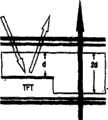
图2示出本发明在反射像素上埋式线栅偏振器的贯通型LCD。FIG. 2 shows a pass-through LCD with embedded wire grid polarizers on reflective pixels according to the present invention.
图3a与3b示出应用垂直对准(VA)LC晶胞的常黑模式。Figures 3a and 3b show a normally black mode using vertically aligned (VA) LC cells.
图4示出图3中常黑模式的计算机模拟的电压相关透射率(VT)与电压相关反射率(VR)曲线。FIG. 4 shows computer simulated voltage-dependent transmittance (VT) and voltage-dependent reflectance (VR) curves of the normally black mode in FIG. 3 .
图5a与5b表示本发明应用90°TN晶胞的另一实施例,图5a示出电压切断态,图5b示出电压接通态。Figures 5a and 5b show another embodiment of the present invention using a 90°TN unit cell, Figure 5a shows the voltage-off state, and Figure 5b shows the voltage-on state.
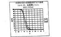
图6示出应用90°TN晶胞的NW模式的计算机模拟的VT与VR曲线。Fig. 6 shows the computer simulated VT and VR curves of the NW mode using the 90° TN unit cell.
图7示出本发明的一器件实施例。Figure 7 shows a device embodiment of the present invention.
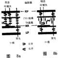
图8a示出应用宽带胆甾型反射器(BCR)、两个环形偏振器和电压为切断态的同质LC晶胞的常白模式。Figure 8a shows the normally white mode using a broadband cholesteric reflector (BCR), two circular polarizers and a homogeneous LC cell with the voltage off.
图8b示出电压为接通态的图8a。Figure 8b shows Figure 8a with the voltage on.
图9a示出应用BCR、两个环形偏振器和电压为切断态的VA LC晶胞的常黑贯通型LCD。Figure 9a shows a normally black feed-through LCD applying a BCR, two circular polarizers and a VA LC cell with the voltage off.
图9b示出电压为接通态的图9a。Figure 9b shows Figure 9a with the voltage on.
具体实施方式Detailed ways
在详述本发明揭示的诸实施例之前,应理解本发明并不限于这里示出的特定结构的细节,因为本发明还拥有其它实施例。而且,本文使用的术语只为了说明,不作为限制。Before the disclosed embodiments of the invention are described in detail, it is to be understood that the invention is not limited to the details of specific construction shown here, for there are other embodiments of the invention as well. Also, the terminology used herein is for the purpose of description and not limitation.
根据本发明内容,本发明为单晶胞隙的透反型液晶显示器TF-LCD提供一种新的器件结构。对全反射型LCD,埋式线栅偏振器(WGP)用作环境光的偏振相关反射器。对贯通型LCD,WGP22只覆盖反射像素24,如图2所示。透射像素用铟锡氧化物与聚酰亚胺LC对准层26覆盖。各种LC对准诸如90°扭绞向列或垂面排列(homeotropic alignment)都可实现常白与常黑模式。本发明方法有价值的独特性在于,该晶胞结构无需任何相位迟后膜而能得到高反差比。According to the contents of the present invention, the present invention provides a new device structure for a transflective liquid crystal display TF-LCD with a single crystal cell gap. For fully reflective LCDs, buried wire grid polarizers (WGPs) are used as polarization-dependent reflectors for ambient light. For a pass-through LCD, WGP 22 only covers
如图1a所示,夏普已揭示了原有技术的单晶胞隙法,晶胞隙必须对反射像素优化,使透射效率大打折扣。图1b所示的原有技术的双晶胞隙结构虽然提高了透射效率,但在显现反射与透射两种图像时,透射像素的响应时间比反射像素的响应时间慢4倍。图1a与1b所示方法的另一缺点是要用两块1/4波射像素的响应时间慢4倍。图1a与1b所示方法的另一缺点是要用两块1/4波膜。一边一块。本文揭示的发明应用单晶胞隙,不需要任何相位迟后膜。再者,本文描述的本发明能获得高的反射率与透射率。As shown in Figure 1a, Sharp has revealed the single-crystal cell gap method of the original technology. The cell gap must be optimized for reflective pixels, which greatly reduces the transmission efficiency. Although the double-crystal cell gap structure of the prior art shown in Fig. 1b improves the transmission efficiency, the response time of the transmission pixel is 4 times slower than that of the reflection pixel when displaying both reflection and transmission images. Another disadvantage of the approach shown in Figures 1a and 1b is the four times slower response time of the pixels using two 1/4 beams. Another disadvantage of the method shown in Figures 1a and 1b is the use of two 1/4 wave films. One piece on each side. The invention disclosed herein utilizes a single crystal cell gap and does not require any phase retardation film. Furthermore, the invention described herein can achieve high reflectance and transmittance.
选择LC模式的灵活性Flexibility in choosing LC mode
根据使用的LC对准,能实现常白(NW)和常黑(NB)两种模式。对NB模式,要求应用负性介电各向异性LC的垂直对准(VA),而对NW模式则应用90°扭绞向列型(TN)晶胞。Depending on the LC alignment used, normally white (NW) and normally black (NB) modes can be realized. For NB mode, vertical alignment (VA) of negative dielectric anisotropy LC is required, while for NW mode, a 90° twisted nematic (TN) unit cell is applied.
常黑模式Normally Black Mode
图3a与3b示出应用VA LC晶胞的NB模式。在电压断开态,除了小于倾角(~2°)外,LC定向器几乎都对准得垂直于基片。顶与底线性偏振器交叉。假设顶线性偏振器发射入射的环境光的P偏振,当P波通过LC层时,没有相位迟后。线栅偏振器定位成发射P波而反射S波,发射的P波再被底线性偏振器吸收,不回射光。在透射通道中,背光的S波透过底线性偏振器并被顶偏振器吸收。因而,反射与透射像素都呈黑色。Figures 3a and 3b show the NB mode using a VA LC unit cell. In the voltage-off state, the LC directors are almost aligned perpendicular to the substrate except for less than a tilt angle (~2°). Top and bottom linear polarizers are crossed. Assuming that the top linear polarizer emits the P polarization of the incident ambient light, there is no phase delay when the P wave passes through the LC layer. The wire grid polarizer is positioned to emit P-waves and reflect S-waves, the emitted P-waves are absorbed by the bottom linear polarizer, no light is retroreflected. In the transmission channel, the S-wave of the backlight is transmitted through the bottom linear polarizer and absorbed by the top polarizer. Thus, both reflective and transmissive pixels appear black.
当施加电压超阈压时,LC定向器被电场定向(图3b)。因使用的LC具有负性介电各向异性(Δε<0),故定向器被定向成平行于基片表面,如图1的右图所示。LC晶胞的作用相当于λ/2板。入射的环境光的P波转换成S波而被WGP反射。S波再次穿过LC半波板而变成P波,最后透过顶偏振器。同样地,顶偏振器发射背光的S波,形成亮态。When the applied voltage exceeds the threshold voltage, the LC director is oriented by the electric field (Fig. 3b). Since the LC used has negative dielectric anisotropy (Δε<0), the director is oriented parallel to the substrate surface, as shown in the right diagram of Figure 1. The LC unit cell acts like a λ/2 plate. The P wave of the incident ambient light is converted into an S wave and reflected by the WGP. The S-wave passes through the LC half-wave plate again to become a P-wave, which finally passes through the top polarizer. Likewise, the top polarizer emits the S wave of the backlight, creating a bright state.
光效率与灰度是贯通型LCD的两个重要参数。图4对图3a与3b所示的常黑模式示出了计算机模拟的电压相关透射率(VT)与电压相关反射率(VR)曲线,R与T像素在5伏都达到100%光调制效率,电压摆动小于3Vrms。Light efficiency and grayscale are two important parameters of the pass-through LCD. Figure 4 shows the computer-simulated voltage-dependent transmittance (VT) and voltage-dependent reflectance (VR) curves for the normally black mode shown in Figures 3a and 3b, both R and T pixels achieve 100% light modulation efficiency at 5 volts , the voltage swing is less than 3Vrms .
常白模式Normally White Mode
图5示出本发明应用90°-TN晶胞的另一实施例。如左图所示,环境光中通过顶偏振器的P波跟随90°TN晶胞的扭绞而变为S波。S波被埋式线栅偏振器反射。S波第二次通过TN晶胞后变为P波而被顶偏振器发射,在零电压时形成亮态。同样在透射像素中,从背光进入的S波被TN晶胞旋转90°而变为P波,该P波透过顶偏振器后形成明亮图像。Fig. 5 shows another embodiment of the present invention using a 90°-TN unit cell. As shown in the figure on the left, the P wave passing through the top polarizer in ambient light becomes an S wave following the twisting of the 90°TN unit cell. S waves are reflected by a buried wire grid polarizer. After the S wave passes through the TN unit cell for the second time, it becomes a P wave and is emitted by the top polarizer, forming a bright state at zero voltage. Also in the transmissive pixel, the S-wave entering from the backlight is rotated by 90° by the TN unit cell to become a P-wave, and the P-wave passes through the top polarizer to form a bright image.
在高压区,LC定向器沿电场方向定向,如图5a与5b右图所示,环境光或背光都见不到任何相位迟后,故观察到黑态。In the high-voltage region, the LC director is oriented along the direction of the electric field, as shown in the right diagrams of Figure 5a and 5b, and neither ambient light nor backlight can see any phase delay, so a black state is observed.
参照图5a与5b,常白贯通型显示器应用90°扭绞向列型(TN)晶胞,图5a示出电压断开态,图5b示出电压接通态。Referring to Figures 5a and 5b, a normally white through-type display uses a 90° twisted nematic (TN) unit cell, Figure 5a shows the voltage-off state, and Figure 5b shows the voltage-on state.
图6绘出NW模式的计算机模拟结果,VT与VR曲线具有十分相似灰度,暗态电压约3Vrms。低工作电压导致低功耗,对移动显示器尤其重要。Fig. 6 shows the computer simulation results of the NW mode, the VT and VR curves have very similar gray scales, and the dark-state voltage is about 3Vrms . Low operating voltage results in low power consumption, which is especially important for mobile displays.
简单设备的制造Manufacturing of Simple Devices
在单偏振器反射型LCD中(见吴(Wu)与杨(Yang)的题为“反射式液晶显示器(Reflective Liquid Crystal Displays)论文,Wiley-SID,2001),薄膜晶体管(TFT)可埋在铝反射器下面,主要优点是TFT孔径比增至约90%,但制造工艺要复杂得多。本发明可使用透射型TFT基片,如图7所示。图7中,TFT与WGP反射器位于不同基片,可分开制作,产量高。In single-polarizer reflective LCDs (see Wu and Yang's paper entitled "Reflective Liquid Crystal Displays", Wiley-SID, 2001), thin-film transistors (TFTs) can be buried in Below the aluminum reflector, the main advantage is that the TFT aperture ratio increases to about 90%, but the manufacturing process is much more complicated. The present invention can use a transmissive TFT substrate, as shown in Figure 7. In Figure 7, TFT and WGP reflector Located on different substrates, they can be manufactured separately with high output.
不需要相位迟后膜No phase retardation film required
通常,无1/4波膜的单偏振器反射型LCD的反差比很差(<10:1),因为该偏振器被用作两个平行的偏振器。本发明中,线栅偏振器与顶片状偏振器一起用作反射像素的交叉偏振器,两偏振器在透射像素上交叉,故本发明提供了高反差比,不需要任何相位迟后膜。Typically, single polarizer reflective LCDs without a 1/4 wave film have a poor contrast ratio (<10:1) because the polarizer is used as two parallel polarizers. In the present invention, the wire grid polarizer is used together with the top sheet polarizer as the crossed polarizer of the reflective pixel, and the two polarizers are crossed on the transmissive pixel, so the present invention provides a high contrast ratio without any retardation film.
本发明的扩展Extension of the invention
线栅偏振器通常用电子束蚀刻或全息照相法制作。为置换WGP,可像图8a志8b那样淀积宽带的胆甾型反射器(BCR)。BCR可用梯度节距胆甾型液晶实现(如勃鲁厄(D.Broe)r等人发表的论文,发表在”Asia Display”1995年第735-8页),此时用两个环形偏振器代替线性偏振器,可实现常白(图8a与8b)与常黑(图9a与9b)两种模式。Wire grid polarizers are usually fabricated by electron beam etching or holography. To replace the WGP, a broadband cholesteric reflector (BCR) can be deposited as shown in Figures 8a-8b. BCR can be realized with gradient pitch cholesteric liquid crystals (such as the papers published by D. Broe r et al., published in "Asia Display" 1995, page 735-8), at this time, two circular polarizers are used Instead of a linear polarizer, two modes, normally white (Figs. 8a and 8b) and normally black (Figs. 9a and 9b), can be realized.
常白模式Normally White Mode
图8a与8b分别表示电压的断与通状态。在电压断态,右侧顶环形偏振器(RCP)发射环境光的左侧偏振。同质晶胞的相位迟后相当于半波板,即dΔn=λ/2,其中d是晶胞隙,Δn是LC双折射率,λ为波长。左侧环形波通过半波LC层后变为右侧环形波,从BCR反射后,右侧波保持不变。这是胆甾型反射器的主要特征。右侧波穿过LC层不止一次,其偏振向左侧旋转并透过右侧的顶环形偏振器。背光也同样透过,形成零电压亮态。Figures 8a and 8b show the off and on states of the voltage, respectively. In the voltage off state, the top right circular polarizer (RCP) emits the left polarization of ambient light. The phase delay of the homogeneous unit cell is equivalent to a half-wave plate, that is, dΔn=λ/2, where d is the unit cell gap, Δn is the LC birefringence index, and λ is the wavelength. The left ring wave becomes the right ring wave after passing through the half-wave LC layer, and the right wave remains unchanged after being reflected from the BCR. This is the main characteristic of cholesteric reflectors. The right wave passes through the LC layer more than once, its polarization rotated to the left and transmitted through the top circular polarizer on the right. The backlight also passes through, forming a zero-voltage bright state.
在高压态,LC定向器被电场定向,使其相位迟后变零。入射的环境光透过BCR被底环形偏振器吸收,透过底偏振器的背光被顶偏振器阻断,呈现暗态。In the high-voltage state, the LC director is oriented by the electric field, making its phase lag and become zero. The incident ambient light passes through the BCR and is absorbed by the bottom circular polarizer, and the backlight passing through the bottom polarizer is blocked by the top polarizer, showing a dark state.
常黑模式Normally Black Mode
另一实施例使用的垂直LC对准和负性介电各向异性(Δε<0)LC材料。图9a与9b示出了工作机理,分别代表电压断与通状态。在电压断态,LC定向器垂直于基片表面,故其相位迟后为零,即δ=0。环境光被底偏振器阻断,背光被顶偏振器阻断,形成良好的暗态。当电压接通使LC层变为半波板时,环境光被反射,背光可透过,看到亮态。Another embodiment uses vertical LC alignment and negative dielectric anisotropy (Δε<0) LC material. Figures 9a and 9b illustrate the working mechanism, representing the voltage off and on states, respectively. In the voltage off state, the LC director is perpendicular to the surface of the substrate, so its phase lag is zero, that is, δ=0. Ambient light is blocked by the bottom polarizer and backlight is blocked by the top polarizer, making for a nice dark state. When the voltage is turned on to make the LC layer become a half-wave plate, the ambient light is reflected, the backlight can pass through, and the bright state can be seen.
本发明可应用于各种商品,诸如Gameboy、电子记事簿(PDA)设备和其它有显示器的手持式设备。The present invention is applicable to a variety of commercial products, such as Gameboys, electronic organizer (PDA) devices, and other handheld devices with displays.
虽然对本发明的某些实施例或实践中设想的修正作了描述与图示,但本发明范围不打算也不看作受此限制,本文提出的其它修正或实施例都被特地保留,因为它们都落在所附如权利要求的范围内。While certain embodiments of the invention or modifications contemplated in practice have been described and illustrated, the scope of the invention is not intended and should not be so limited, and other modifications or embodiments set forth herein are expressly reserved because they All fall within the scope of the appended claims.
Claims (14)
Applications Claiming Priority (2)
| Application Number | Priority Date | Filing Date | Title |
|---|---|---|---|
| US37886202P | 2002-05-07 | 2002-05-07 | |
| US60/378,862 | 2002-05-07 |
Publications (2)
| Publication Number | Publication Date |
|---|---|
| CN1678949A CN1678949A (en) | 2005-10-05 |
| CN100474058Ctrue CN100474058C (en) | 2009-04-01 |
Family
ID=29420448
Family Applications (1)
| Application Number | Title | Priority Date | Filing Date |
|---|---|---|---|
| CNB038149990AExpired - Fee RelatedCN100474058C (en) | 2002-05-07 | 2003-05-02 | Reflective and transflective liquid crystal display using a wire grid polarizer and manufacturing method thereof |
Country Status (4)
| Country | Link |
|---|---|
| US (1) | US6977702B2 (en) |
| CN (1) | CN100474058C (en) |
| AU (1) | AU2003234341A1 (en) |
| WO (1) | WO2003096111A1 (en) |
Families Citing this family (77)
| Publication number | Priority date | Publication date | Assignee | Title |
|---|---|---|---|---|
| US5910854A (en) | 1993-02-26 | 1999-06-08 | Donnelly Corporation | Electrochromic polymeric solid films, manufacturing electrochromic devices using such solid films, and processes for making such solid films and devices |
| US5668663A (en) | 1994-05-05 | 1997-09-16 | Donnelly Corporation | Electrochromic mirrors and devices |
| US6891563B2 (en) | 1996-05-22 | 2005-05-10 | Donnelly Corporation | Vehicular vision system |
| US8294975B2 (en) | 1997-08-25 | 2012-10-23 | Donnelly Corporation | Automotive rearview mirror assembly |
| US6124886A (en) | 1997-08-25 | 2000-09-26 | Donnelly Corporation | Modular rearview mirror assembly |
| US6326613B1 (en) | 1998-01-07 | 2001-12-04 | Donnelly Corporation | Vehicle interior mirror assembly adapted for containing a rain sensor |
| US6172613B1 (en) | 1998-02-18 | 2001-01-09 | Donnelly Corporation | Rearview mirror assembly incorporating vehicle information display |
| US6445287B1 (en) | 2000-02-28 | 2002-09-03 | Donnelly Corporation | Tire inflation assistance monitoring system |
| US8288711B2 (en) | 1998-01-07 | 2012-10-16 | Donnelly Corporation | Interior rearview mirror system with forwardly-viewing camera and a control |
| US6329925B1 (en) | 1999-11-24 | 2001-12-11 | Donnelly Corporation | Rearview mirror assembly with added feature modular display |
| US6693517B2 (en) | 2000-04-21 | 2004-02-17 | Donnelly Corporation | Vehicle mirror assembly communicating wirelessly with vehicle accessories and occupants |
| US6477464B2 (en) | 2000-03-09 | 2002-11-05 | Donnelly Corporation | Complete mirror-based global-positioning system (GPS) navigation solution |
| AU2001243285A1 (en) | 2000-03-02 | 2001-09-12 | Donnelly Corporation | Video mirror systems incorporating an accessory module |
| US7370983B2 (en) | 2000-03-02 | 2008-05-13 | Donnelly Corporation | Interior mirror assembly with display |
| US7167796B2 (en) | 2000-03-09 | 2007-01-23 | Donnelly Corporation | Vehicle navigation system for use with a telematics system |
| AU2002251807A1 (en) | 2001-01-23 | 2002-08-19 | Donnelly Corporation | Improved vehicular lighting system for a mirror assembly |
| US7581859B2 (en) | 2005-09-14 | 2009-09-01 | Donnelly Corp. | Display device for exterior rearview mirror |
| US7255451B2 (en) | 2002-09-20 | 2007-08-14 | Donnelly Corporation | Electro-optic mirror cell |
| JP4334191B2 (en)* | 2001-11-07 | 2009-09-30 | 大日本印刷株式会社 | Substrate provided with cholesteric layer and display device provided with the substrate |
| JP4141708B2 (en)* | 2002-03-11 | 2008-08-27 | シャープ株式会社 | Liquid crystal display device and driving method thereof |
| US6918674B2 (en) | 2002-05-03 | 2005-07-19 | Donnelly Corporation | Vehicle rearview mirror system |
| AU2003237424A1 (en) | 2002-06-06 | 2003-12-22 | Donnelly Corporation | Interior rearview mirror system with compass |
| US7329013B2 (en) | 2002-06-06 | 2008-02-12 | Donnelly Corporation | Interior rearview mirror system with compass |
| JP2004053896A (en)* | 2002-07-19 | 2004-02-19 | Sharp Corp | Display device |
| US7310177B2 (en) | 2002-09-20 | 2007-12-18 | Donnelly Corporation | Electro-optic reflective element assembly |
| WO2004026633A2 (en) | 2002-09-20 | 2004-04-01 | Donnelly Corporation | Mirror reflective element assembly |
| US6894750B2 (en)* | 2003-05-01 | 2005-05-17 | Motorola Inc. | Transflective color liquid crystal display with internal rear polarizer |
| US7446924B2 (en) | 2003-10-02 | 2008-11-04 | Donnelly Corporation | Mirror reflective element assembly including electronic component |
| US7308341B2 (en) | 2003-10-14 | 2007-12-11 | Donnelly Corporation | Vehicle communication system |
| CN100376991C (en)* | 2004-02-14 | 2008-03-26 | 鸿富锦精密工业(深圳)有限公司 | Liquid crystal display device |
| US7965357B2 (en)* | 2004-04-15 | 2011-06-21 | Chimei Innolux Corporation | Transflective LCD display device comprising a patterned polarizer, display having the same, and method having the same |
| US8282224B2 (en) | 2004-07-12 | 2012-10-09 | Gentex Corporation | Rearview mirror assemblies with anisotropic polymer laminates |
| US7502156B2 (en)* | 2004-07-12 | 2009-03-10 | Gentex Corporation | Variable reflectance mirrors and windows |
| US8545030B2 (en) | 2004-07-12 | 2013-10-01 | Gentex Corporation | Rearview mirror assemblies with anisotropic polymer laminates |
| JP2006030889A (en)* | 2004-07-21 | 2006-02-02 | Toshiba Matsushita Display Technology Co Ltd | Liquid crystal display device |
| KR20060042481A (en)* | 2004-11-09 | 2006-05-15 | 엘지전자 주식회사 | Liquid Crystal Display Including Reflective Polarizer |
| US20080013021A1 (en)* | 2004-12-10 | 2008-01-17 | Gugliotta Eleni E | Cellular telephone and personal viewing mirror combination |
| KR100710172B1 (en)* | 2004-12-29 | 2007-04-20 | 엘지.필립스 엘시디 주식회사 | Liquid crystal display |
| EP1883855B1 (en) | 2005-05-16 | 2011-07-20 | Donnelly Corporation | Vehicle mirror assembly with indicia at reflective element |
| CN100432774C (en)* | 2005-08-15 | 2008-11-12 | 中华映管股份有限公司 | transflective liquid crystal display |
| KR100718136B1 (en)* | 2005-08-30 | 2007-05-14 | 삼성전자주식회사 | Backlight unit using wire grid polarizer and liquid crystal display device using same |
| EP1949666B1 (en) | 2005-11-01 | 2013-07-17 | Magna Mirrors of America, Inc. | Interior rearview mirror with display |
| US7576720B2 (en)* | 2005-11-30 | 2009-08-18 | Au Optronics Corporation | Transflective liquid crystal display |
| TWI318315B (en)* | 2006-07-12 | 2009-12-11 | Au Optronics Corp | Transflective liquid crystal panel and method of making the same |
| US20080204636A1 (en)* | 2007-02-26 | 2008-08-28 | Chi Mei Optoelectronics Corporation | Transflective liquid crystal display |
| KR101350873B1 (en)* | 2007-03-08 | 2014-01-13 | 삼성디스플레이 주식회사 | Liquid crystal display device |
| US7589808B2 (en)* | 2007-06-15 | 2009-09-15 | University Of Central Florida Research Foundation, Inc. | Wide viewing angle transflective liquid crystal displays |
| US20080309854A1 (en)* | 2007-06-15 | 2008-12-18 | Zhibing Ge | Wide Viewing Angle and Broadband Circular Polarizers for Transflective Liquid Crystal Displays |
| US7605897B2 (en)* | 2007-07-20 | 2009-10-20 | University Of Central Florida Research Foundation Inc. | Multi-domain vertical alignment liquid crystal displays with improved angular dependent gamma curves |
| US8089590B2 (en) | 2007-08-06 | 2012-01-03 | Chimei Innolux Corporation | Transflective liquid crystal display |
| US7583439B2 (en)* | 2007-08-09 | 2009-09-01 | University Of Central Florida Research Foundation, Inc. | Wide-angle and broadband polarization converter |
| JP2009123553A (en)* | 2007-11-15 | 2009-06-04 | Sumitomo Chemical Co Ltd | Light guide plate, surface light source device, and liquid crystal display device |
| US8154418B2 (en) | 2008-03-31 | 2012-04-10 | Magna Mirrors Of America, Inc. | Interior rearview mirror system |
| US9254789B2 (en) | 2008-07-10 | 2016-02-09 | Gentex Corporation | Rearview mirror assemblies with anisotropic polymer laminates |
| US9487144B2 (en) | 2008-10-16 | 2016-11-08 | Magna Mirrors Of America, Inc. | Interior mirror assembly with display |
| CN101989012A (en)* | 2009-08-03 | 2011-03-23 | 江苏丽恒电子有限公司 | Liquid crystal on silicon imager |
| KR20110057981A (en)* | 2009-11-25 | 2011-06-01 | 삼성전자주식회사 | Liquid Crystal Display and Manufacturing Method Thereof |
| KR20110101893A (en)* | 2010-03-10 | 2011-09-16 | 삼성전자주식회사 | Liquid crystal display |
| US20140092347A1 (en)* | 2011-09-01 | 2014-04-03 | Sharp Kabushiki Kaisha | Liquid crystal display panel and liquid crystal display device |
| CN103087726B (en)* | 2013-01-25 | 2015-03-18 | 北京京东方光电科技有限公司 | Liquid crystal orientation layer composition, semi-transparent reflective liquid crystal panel and manufacturing method of semi-transparent reflective liquid crystal panel |
| US9547395B2 (en) | 2013-10-16 | 2017-01-17 | Microsoft Technology Licensing, Llc | Touch and hover sensing with conductive polarizer |
| CN103995405B (en)* | 2014-05-09 | 2015-08-05 | 京东方科技集团股份有限公司 | A kind of semi-transparent semi-reflective liquid crystal panel and preparation method thereof, liquid crystal indicator |
| KR20160029188A (en) | 2014-09-04 | 2016-03-15 | 삼성디스플레이 주식회사 | Method for manufacturing reflective polarizing plate |
| KR20160112067A (en)* | 2015-03-17 | 2016-09-28 | 삼성디스플레이 주식회사 | Optical device including light modulatoin device and driving method thereof |
| CN105467499A (en)* | 2016-01-15 | 2016-04-06 | 京东方科技集团股份有限公司 | Metal wire grating polaroid and manufacturing method thereof, display panel and display device |
| CN105446001B (en)* | 2016-01-25 | 2018-09-04 | 京东方科技集团股份有限公司 | A kind of display panel and its working method, display device |
| CN106526952A (en)* | 2016-12-26 | 2017-03-22 | 南京中电熊猫液晶显示科技有限公司 | Color film substrate and manufacturing method thereof and liquid crystal displayer |
| KR20200003295A (en) | 2017-05-16 | 2020-01-08 | 어플라이드 머티어리얼스, 인코포레이티드 | Wire grid polarizer manufacturing methods using frequency doubling interference lithography |
| JP2019124775A (en)* | 2018-01-15 | 2019-07-25 | セイコーエプソン株式会社 | Liquid crystal device and electronic apparatus |
| CN108919496A (en)* | 2018-08-08 | 2018-11-30 | 京东方科技集团股份有限公司 | The low-power consumption HUD system of solar radiation protection |
| WO2020155027A1 (en)* | 2019-01-31 | 2020-08-06 | 京东方科技集团股份有限公司 | Backlight source, backlight module, and display device |
| CN111095288B (en)* | 2019-12-02 | 2023-09-05 | 深圳市汇顶科技股份有限公司 | Under-screen optical fingerprint identification device and system and liquid crystal display screen |
| US20230076172A1 (en)* | 2020-01-31 | 2023-03-09 | Zeon Corporation | Identification medium, article, and identification medium use method |
| CN111580302B (en)* | 2020-06-16 | 2023-01-10 | 京东方科技集团股份有限公司 | Reflective liquid crystal display panel and display device |
| US20230342444A1 (en)* | 2020-10-01 | 2023-10-26 | Fingerprint Cards Anacatum Ip Ab | Biometric imaging arrangement for infrared imaging comprising microlenses |
| CN116360168B (en)* | 2023-05-11 | 2023-08-18 | 惠科股份有限公司 | display device |
| CN119224907A (en)* | 2023-06-30 | 2024-12-31 | 福州京东方光电科技有限公司 | Compensation film, polarizer, liquid crystal display panel and display device |
Citations (3)
| Publication number | Priority date | Publication date | Assignee | Title |
|---|---|---|---|---|
| US5986730A (en)* | 1998-12-01 | 1999-11-16 | Moxtek | Dual mode reflective/transmissive liquid crystal display apparatus |
| US6008871A (en)* | 1997-01-20 | 1999-12-28 | Seiko Epson Corporation | Transflective liquid crystal display device having a reflective polarizer |
| US6348995B1 (en)* | 1998-07-16 | 2002-02-19 | Moxtek | Reflective optical polarizer device with controlled light distribution and liquid crystal display incorporating the same |
Family Cites Families (10)
| Publication number | Priority date | Publication date | Assignee | Title |
|---|---|---|---|---|
| US4688897A (en)* | 1985-06-17 | 1987-08-25 | Hughes Aircraft Company | Liquid crystal device |
| US5751388A (en)* | 1995-04-07 | 1998-05-12 | Honeywell Inc. | High efficiency polarized display |
| JP3935936B2 (en)* | 1995-06-26 | 2007-06-27 | スリーエム カンパニー | Transflective display with reflective polarizing transflective reflector |
| US5764324A (en) | 1997-01-22 | 1998-06-09 | International Business Machines Corporation | Flicker-free reflective liquid crystal cell |
| US6330047B1 (en) | 1997-07-28 | 2001-12-11 | Sharp Kabushiki Kaisha | Liquid crystal display device and method for fabricating the same |
| US6281952B1 (en)* | 1997-12-26 | 2001-08-28 | Sharp Kabushiki Kaisha | Liquid crystal display |
| US6295109B1 (en) | 1997-12-26 | 2001-09-25 | Sharp Kabushiki Kaisha | LCD with plurality of pixels having reflective and transmissive regions |
| US6108131A (en) | 1998-05-14 | 2000-08-22 | Moxtek | Polarizer apparatus for producing a generally polarized beam of light |
| JP3406242B2 (en) | 1998-10-15 | 2003-05-12 | シャープ株式会社 | Liquid crystal display |
| US6563638B2 (en)* | 2001-04-26 | 2003-05-13 | Raytheon Company | Wide-angle collimating optical device |
- 2003
- 2003-05-02USUS10/428,386patent/US6977702B2/ennot_activeExpired - Fee Related
- 2003-05-02CNCNB038149990Apatent/CN100474058C/ennot_activeExpired - Fee Related
- 2003-05-02WOPCT/US2003/013676patent/WO2003096111A1/ennot_activeApplication Discontinuation
- 2003-05-02AUAU2003234341Apatent/AU2003234341A1/ennot_activeAbandoned
Patent Citations (3)
| Publication number | Priority date | Publication date | Assignee | Title |
|---|---|---|---|---|
| US6008871A (en)* | 1997-01-20 | 1999-12-28 | Seiko Epson Corporation | Transflective liquid crystal display device having a reflective polarizer |
| US6348995B1 (en)* | 1998-07-16 | 2002-02-19 | Moxtek | Reflective optical polarizer device with controlled light distribution and liquid crystal display incorporating the same |
| US5986730A (en)* | 1998-12-01 | 1999-11-16 | Moxtek | Dual mode reflective/transmissive liquid crystal display apparatus |
Also Published As
| Publication number | Publication date |
|---|---|
| WO2003096111A1 (en) | 2003-11-20 |
| US20030210369A1 (en) | 2003-11-13 |
| AU2003234341A8 (en) | 2003-11-11 |
| AU2003234341A1 (en) | 2003-11-11 |
| CN1678949A (en) | 2005-10-05 |
| US6977702B2 (en) | 2005-12-20 |
Similar Documents
| Publication | Publication Date | Title |
|---|---|---|
| CN100474058C (en) | Reflective and transflective liquid crystal display using a wire grid polarizer and manufacturing method thereof | |
| JP3380482B2 (en) | Liquid crystal display | |
| JP4526590B2 (en) | Method for forming optical λ / 4 layer for transflective liquid crystal display device | |
| US20100026930A1 (en) | Diffractive liquid crystal display | |
| CN102096227B (en) | Transflective liquid crystal display device | |
| JP2008077119A (en) | Liquid crystal display device using dual light unit | |
| EP0935155A1 (en) | Display and electronic device equipped with the same | |
| JP3506249B2 (en) | Liquid crystal display | |
| JP3946569B2 (en) | Liquid crystal display | |
| JP3464475B2 (en) | Liquid crystal display | |
| KR100786475B1 (en) | liquid crystal display and driving method thereof | |
| KR101192755B1 (en) | Transflective Type Liquid Crystal Display Device | |
| JP3946745B2 (en) | Liquid crystal display | |
| JP2002333624A5 (en) | ||
| JP3506250B2 (en) | Liquid crystal display device and driving method thereof | |
| JP2003161944A (en) | Liquid crystal display | |
| JP3946743B2 (en) | Liquid crystal display | |
| JP3946742B2 (en) | Liquid crystal display | |
| JP3946741B2 (en) | Liquid crystal display | |
| JP3946738B2 (en) | Liquid crystal display | |
| JP3946740B2 (en) | Liquid crystal display | |
| JP3946744B2 (en) | Liquid crystal display | |
| JP3946746B2 (en) | Liquid crystal display | |
| CN115826305A (en) | Liquid crystal display panel and display device | |
| KR20110054424A (en) | Liquid crystal display |
Legal Events
| Date | Code | Title | Description |
|---|---|---|---|
| C06 | Publication | ||
| PB01 | Publication | ||
| C10 | Entry into substantive examination | ||
| SE01 | Entry into force of request for substantive examination | ||
| C14 | Grant of patent or utility model | ||
| GR01 | Patent grant | ||
| CF01 | Termination of patent right due to non-payment of annual fee | Granted publication date:20090401 Termination date:20150502 | |
| EXPY | Termination of patent right or utility model |