CN100473940C - Portable coordinate measurement machine with articulated jib - Google Patents
Portable coordinate measurement machine with articulated jibDownload PDFInfo
- Publication number
- CN100473940C CN100473940CCNB038036789ACN03803678ACN100473940CCN 100473940 CCN100473940 CCN 100473940CCN B038036789 ACNB038036789 ACN B038036789ACN 03803678 ACN03803678 ACN 03803678ACN 100473940 CCN100473940 CCN 100473940C
- Authority
- CN
- China
- Prior art keywords
- measuring machine
- coordinate measuring
- joint
- joints
- read heads
- Prior art date
- Legal status (The legal status is an assumption and is not a legal conclusion. Google has not performed a legal analysis and makes no representation as to the accuracy of the status listed.)
- Expired - Fee Related
Links
Images


Classifications
- G—PHYSICS
- G01—MEASURING; TESTING
- G01B—MEASURING LENGTH, THICKNESS OR SIMILAR LINEAR DIMENSIONS; MEASURING ANGLES; MEASURING AREAS; MEASURING IRREGULARITIES OF SURFACES OR CONTOURS
- G01B11/00—Measuring arrangements characterised by the use of optical techniques
- G01B11/24—Measuring arrangements characterised by the use of optical techniques for measuring contours or curvatures
- G01B11/25—Measuring arrangements characterised by the use of optical techniques for measuring contours or curvatures by projecting a pattern, e.g. one or more lines, moiré fringes on the object
- B—PERFORMING OPERATIONS; TRANSPORTING
- B23—MACHINE TOOLS; METAL-WORKING NOT OTHERWISE PROVIDED FOR
- B23Q—DETAILS, COMPONENTS, OR ACCESSORIES FOR MACHINE TOOLS, e.g. ARRANGEMENTS FOR COPYING OR CONTROLLING; MACHINE TOOLS IN GENERAL CHARACTERISED BY THE CONSTRUCTION OF PARTICULAR DETAILS OR COMPONENTS; COMBINATIONS OR ASSOCIATIONS OF METAL-WORKING MACHINES, NOT DIRECTED TO A PARTICULAR RESULT
- B23Q35/00—Control systems or devices for copying directly from a pattern or a master model; Devices for use in copying manually
- B23Q35/04—Control systems or devices for copying directly from a pattern or a master model; Devices for use in copying manually using a feeler or the like travelling along the outline of the pattern, model or drawing; Feelers, patterns, or models therefor
- B—PERFORMING OPERATIONS; TRANSPORTING
- B25—HAND TOOLS; PORTABLE POWER-DRIVEN TOOLS; MANIPULATORS
- B25J—MANIPULATORS; CHAMBERS PROVIDED WITH MANIPULATION DEVICES
- B25J17/00—Joints
- B25J17/02—Wrist joints
- B25J17/0241—One-dimensional joints
- B25J17/025—One-dimensional joints mounted in series
- B—PERFORMING OPERATIONS; TRANSPORTING
- B25—HAND TOOLS; PORTABLE POWER-DRIVEN TOOLS; MANIPULATORS
- B25J—MANIPULATORS; CHAMBERS PROVIDED WITH MANIPULATION DEVICES
- B25J19/00—Accessories fitted to manipulators, e.g. for monitoring, for viewing; Safety devices combined with or specially adapted for use in connection with manipulators
- B25J19/0008—Balancing devices
- B25J19/0016—Balancing devices using springs
- B—PERFORMING OPERATIONS; TRANSPORTING
- B25—HAND TOOLS; PORTABLE POWER-DRIVEN TOOLS; MANIPULATORS
- B25J—MANIPULATORS; CHAMBERS PROVIDED WITH MANIPULATION DEVICES
- B25J19/00—Accessories fitted to manipulators, e.g. for monitoring, for viewing; Safety devices combined with or specially adapted for use in connection with manipulators
- B25J19/0091—Shock absorbers
- B—PERFORMING OPERATIONS; TRANSPORTING
- B25—HAND TOOLS; PORTABLE POWER-DRIVEN TOOLS; MANIPULATORS
- B25J—MANIPULATORS; CHAMBERS PROVIDED WITH MANIPULATION DEVICES
- B25J9/00—Programme-controlled manipulators
- B25J9/0009—Constructional details, e.g. manipulator supports, bases
- B25J9/0012—Constructional details, e.g. manipulator supports, bases making use of synthetic construction materials, e.g. plastics, composites
- B—PERFORMING OPERATIONS; TRANSPORTING
- B25—HAND TOOLS; PORTABLE POWER-DRIVEN TOOLS; MANIPULATORS
- B25J—MANIPULATORS; CHAMBERS PROVIDED WITH MANIPULATION DEVICES
- B25J9/00—Programme-controlled manipulators
- B25J9/02—Programme-controlled manipulators characterised by movement of the arms, e.g. cartesian coordinate type
- B25J9/023—Cartesian coordinate type
- B—PERFORMING OPERATIONS; TRANSPORTING
- B25—HAND TOOLS; PORTABLE POWER-DRIVEN TOOLS; MANIPULATORS
- B25J—MANIPULATORS; CHAMBERS PROVIDED WITH MANIPULATION DEVICES
- B25J9/00—Programme-controlled manipulators
- B25J9/06—Programme-controlled manipulators characterised by multi-articulated arms
- B—PERFORMING OPERATIONS; TRANSPORTING
- B25—HAND TOOLS; PORTABLE POWER-DRIVEN TOOLS; MANIPULATORS
- B25J—MANIPULATORS; CHAMBERS PROVIDED WITH MANIPULATION DEVICES
- B25J9/00—Programme-controlled manipulators
- B25J9/16—Programme controls
- B25J9/1602—Programme controls characterised by the control system, structure, architecture
- G—PHYSICS
- G01—MEASURING; TESTING
- G01B—MEASURING LENGTH, THICKNESS OR SIMILAR LINEAR DIMENSIONS; MEASURING ANGLES; MEASURING AREAS; MEASURING IRREGULARITIES OF SURFACES OR CONTOURS
- G01B11/00—Measuring arrangements characterised by the use of optical techniques
- G01B11/002—Measuring arrangements characterised by the use of optical techniques for measuring two or more coordinates
- G01B11/005—Measuring arrangements characterised by the use of optical techniques for measuring two or more coordinates coordinate measuring machines
- G—PHYSICS
- G01—MEASURING; TESTING
- G01B—MEASURING LENGTH, THICKNESS OR SIMILAR LINEAR DIMENSIONS; MEASURING ANGLES; MEASURING AREAS; MEASURING IRREGULARITIES OF SURFACES OR CONTOURS
- G01B11/00—Measuring arrangements characterised by the use of optical techniques
- G01B11/02—Measuring arrangements characterised by the use of optical techniques for measuring length, width or thickness
- G01B11/03—Measuring arrangements characterised by the use of optical techniques for measuring length, width or thickness by measuring coordinates of points
- G—PHYSICS
- G01—MEASURING; TESTING
- G01B—MEASURING LENGTH, THICKNESS OR SIMILAR LINEAR DIMENSIONS; MEASURING ANGLES; MEASURING AREAS; MEASURING IRREGULARITIES OF SURFACES OR CONTOURS
- G01B21/00—Measuring arrangements or details thereof, where the measuring technique is not covered by the other groups of this subclass, unspecified or not relevant
- G01B21/02—Measuring arrangements or details thereof, where the measuring technique is not covered by the other groups of this subclass, unspecified or not relevant for measuring length, width, or thickness
- G01B21/04—Measuring arrangements or details thereof, where the measuring technique is not covered by the other groups of this subclass, unspecified or not relevant for measuring length, width, or thickness by measuring coordinates of points
- G01B21/045—Correction of measurements
- G—PHYSICS
- G01—MEASURING; TESTING
- G01B—MEASURING LENGTH, THICKNESS OR SIMILAR LINEAR DIMENSIONS; MEASURING ANGLES; MEASURING AREAS; MEASURING IRREGULARITIES OF SURFACES OR CONTOURS
- G01B5/00—Measuring arrangements characterised by the use of mechanical techniques
- G01B5/004—Measuring arrangements characterised by the use of mechanical techniques for measuring coordinates of points
- G01B5/008—Measuring arrangements characterised by the use of mechanical techniques for measuring coordinates of points using coordinate measuring machines
- G—PHYSICS
- G06—COMPUTING OR CALCULATING; COUNTING
- G06T—IMAGE DATA PROCESSING OR GENERATION, IN GENERAL
- G06T7/00—Image analysis
- G06T7/50—Depth or shape recovery
- G06T7/521—Depth or shape recovery from laser ranging, e.g. using interferometry; from the projection of structured light
- Y—GENERAL TAGGING OF NEW TECHNOLOGICAL DEVELOPMENTS; GENERAL TAGGING OF CROSS-SECTIONAL TECHNOLOGIES SPANNING OVER SEVERAL SECTIONS OF THE IPC; TECHNICAL SUBJECTS COVERED BY FORMER USPC CROSS-REFERENCE ART COLLECTIONS [XRACs] AND DIGESTS
- Y10—TECHNICAL SUBJECTS COVERED BY FORMER USPC
- Y10S—TECHNICAL SUBJECTS COVERED BY FORMER USPC CROSS-REFERENCE ART COLLECTIONS [XRACs] AND DIGESTS
- Y10S33/00—Geometrical instruments
- Y10S33/01—Magnetic
Landscapes
- Engineering & Computer Science (AREA)
- Mechanical Engineering (AREA)
- Physics & Mathematics (AREA)
- Robotics (AREA)
- General Physics & Mathematics (AREA)
- Automation & Control Theory (AREA)
- Computer Vision & Pattern Recognition (AREA)
- Optics & Photonics (AREA)
- Theoretical Computer Science (AREA)
- Length Measuring Devices With Unspecified Measuring Means (AREA)
- A Measuring Device Byusing Mechanical Method (AREA)
- Length Measuring Devices By Optical Means (AREA)
Abstract
Translated fromChinese
Description
Translated fromChinese技术领域technical field
本发明总体上涉及一种坐标测量机(CMM),并且尤其涉及一种具有铰接臂的便携式CMM。The present invention relates generally to a coordinate measuring machine (CMM), and more particularly to a portable CMM with an articulated arm.
发明背景Background of the invention
目前,提出了一种作为测量系统的带有主机和应用软件的便携式铰接臂。该铰接臂通常用来对一物体上的一些点进行测量,并且将这些测量到的点与存储在该主机中的计算机辅助设计(CAD)数据进行比较以便确定该物体是否处于位于CAD规范(CAD specification)之内。换句话说,该CAD数据为基准数据,由该铰接臂进行测量后所获得的实际测量值与给基准数据进行比较。主机内也可以含有应用软件来引导操作者进行该检查过程。在涉及复杂应用的多种情况下,这种安排是比较合适的,因为使用者将会在对应用软件中的复杂命令作出响应的同时观察到该主机上的三维CAD数据。Currently, a portable articulated arm with a host computer and application software is proposed as a measurement system. The articulated arm is generally used to measure points on an object, and compare these measured points with computer-aided design (CAD) data stored in the host computer to determine whether the object is within the CAD specification (CAD specification). In other words, the CAD data is the reference data, and the actual measured value obtained after the measurement by the articulated arm is compared with the reference data. The host may also contain application software to guide the operator through the inspection process. In many cases involving complex applications, this arrangement is appropriate because the user will be viewing the 3D CAD data on the host computer while responding to complex commands in the application software.
美国专利US5402582(下面简称为‘582)披露了一种用于上述测量系统中的现有的便携式CMM的例子,该专利被转让给了本发明的受让人,该专利在此以参引方式包含在本申请中。该专利‘582披露了一种普通的三维测量系统,该三维测量系统包括一种可人工操作的具有多个关节的铰接臂,该铰接臂的一端具有一支承基座而在其另一端具有一测量探针。一主机通过一中间控制器或一串行盒(serial box)与该铰接臂相联通。可以理解的是,在该专利‘582中,该铰接臂将会与该串行盒进行电子通信,反之,该串行盒也与该主机进行电子通信。共同转让的美国专利US5611147(下面简称为‘147)也以参引的方式包含在本申请中,该专利‘147披露了一种类似的具有铰接臂的CMM。在该专利‘147中,该铰接臂包括一些重要的特征,包括:在该探针末端处的一附加的旋转轴用来为一臂提供一种2-1-3或2-2-3关节结构(后一种情况为一种7轴臂),以及用于该臂中的轴承的改进的预加载荷的轴承结构。An example of an existing portable CMM for use in the measurement system described above is disclosed in U.S. Patent No. 5,402,582 (hereinafter referred to as '582), assigned to the assignee of the present invention, which patent is hereby incorporated by reference included in this application. The '582 patent discloses a general three-dimensional measurement system that includes a manually operable articulated arm with a support base at one end and a support base at the other end. Measuring probe. A host communicates with the articulated arm through an intermediate controller or a serial box. It will be appreciated that in the '582 patent the articulated arm will be in electronic communication with the serial box which in turn will be in electronic communication with the host. Commonly assigned U.S. Patent No. 5,611,147 (hereinafter referred to as '147), also incorporated herein by reference, discloses a similar CMM with an articulated arm. In the '147 patent, the articulated arm includes some important features, including: an additional axis of rotation at the end of the probe to provide a 2-1-3 or 2-2-3 joint for an arm structure (in the latter case a 7-axis arm), and an improved preloaded bearing structure for the bearings in the arm.
还有其他相关的现有CMM,包括共同转让的美国专利US5926782(下面简称为‘782)以及美国专利US5956857(下面简称为‘857),专利‘782提供了一种铰接臂,该铰接臂具有可锁定的转换壳体,以便消除一个或多个自由度;专利‘857提供了一种快速断开的安装系统。There are other related prior CMMs, including commonly assigned U.S. Patent No. 5,926,782 (hereinafter referred to as '782) and U.S. Patent No. 5,956,857 (hereinafter referred to as '857), which provides an articulated arm with a Locking transition housing to eliminate one or more degrees of freedom; the '857 patent provides a quick disconnect mounting system.
这里所描述的较多的现有类型的便携式CMM都不是必须采用一种中间控制器或串行盒,因为其功能现在被包含在主机所提供了的软件中。例如,共同转让的美国专利US5978748(下面简称为‘748,在此以参引的方式包含在本申请中)披露了一种具有在板控制器(on-board controller)铰接臂,该在板控制器存储有一个或多个可执行的程序并且为使用者提供指令(例如检查步骤)以及存储作为基准数据的CAD数据。在专利‘748中,一控制器安装在该铰接臂上并运行该可执行程序,该可执行程序指导使用者经过例如象检查步骤一样的过程。在这样一种系统中,可以采用一主机来生成该可执行程序。安装在该铰接臂上的控制器用来运行该可执行程序但是不能用来生成可执行程序或修改可执行程序。通过模拟一些视频游戏系统(video gamingsystem),该主机起到了用于书写视频游戏或修改视频游戏的平台的作用,而该安装在铰接臂上的控制器起到了运行视频游戏的平台的作用。该控制器(例如,就象游戏的玩家)不能对该可执行程序进行修改。如在专利‘748中所述,由于消除每个铰接臂都需要配备一台主机的需求,因此获得了一种低成本的三维坐标测量系统。转让给本申请的受让人的美国专利申请No.09/775236(下面简称为‘236,并以参引方式包含在本申请中)披露了一种用于向使用专利‘748中披露的坐标测量系统的使用者发送可执行程序的方法和系统。该方法包括:接受客户要求生成一可执行程序的请求并获得与该可执行程序相关的信息;随后开发出该可执行程序,该可执行程序可引导操作者经过一些采用该三维坐标测量系统将要执行的测量步骤。优选是通过在线网络例如英特网将该可执行程序发送给该客户。The more existing types of portable CMMs described here do not necessarily employ an intermediate controller or serial box, since the functionality is now contained in the software provided by the host. For example, commonly assigned U.S. Patent No. 5,978,748 (hereinafter referred to simply as '748, which is incorporated herein by reference) discloses an articulated arm with an on-board controller that The memory stores one or more executable programs and provides instructions for the user (such as inspection steps) and stores CAD data as reference data. In the '748 patent, a controller is mounted on the articulated arm and runs the executable program that guides the user through procedures such as inspection steps. In such a system, a host computer may be used to generate the executable program. The controller mounted on the articulated arm is used to run the executable program but cannot be used to create or modify the executable program. By simulating some video gaming systems, the mainframe functions as a platform for writing or modifying video games, and the controller mounted on the articulating arm functions as a platform for running video games. The controller (eg, like the player of the game) cannot make modifications to the executable. As described in the '748 patent, by eliminating the need for a mainframe for each articulated arm, a low cost three-dimensional coordinate measurement system is obtained. U.S. Patent Application No. 09/775,236, assigned to the assignee of the present application (hereinafter referred to as '236, and incorporated herein by reference), discloses a method for using the coordinates disclosed in the '748 patent. A method and system for delivering an executable program by a user of a measurement system. The method includes: accepting a customer's request to generate an executable program and obtaining information related to the executable program; then developing the executable program, the executable program can guide the operator through some The measurement steps performed. The executable program is preferably sent to the client via an online network such as the Internet.
共同转让的美国专利US6131299(下面简称为‘299,其所有内容都在此以参引的方式包含在本申请中)披露了一种其上布置有一显示装置的铰接臂,该显示装置便于操作者获得位置数据的方便显示和系统菜单提示。该显示装置包括例如LED,该LED可表明系统是否通电、转换器位置状况以及出错情况。转让给本申请的受让人的美国专利US6219928(下面简称为‘928,在此以参引的方式包含在本申请中)披露了一种用于铰接臂的串行网络(serial network)。该串行网络将位于该铰接臂中的转换器的数据传送到一控制器。每个转换器都包括一带有存储器的转换器接口(transducer interface),该存储器储存转换器数据。该控制器对每个存储器进行串行寻址并将数据从该转换器接口存储器传送到该控制器。共同转让的美国专利US66253458以及US6298569(下面分别简称为‘458以及‘569)都披露了用于在此所描述的那种铰接臂便携式CMM的可调节的平衡机构。Commonly assigned U.S. Patent No. 6,131,299 (hereafter referred to simply as '299, the entire contents of which are hereby incorporated by reference into this application) discloses an articulated arm on which is arranged a display device for the convenience of the operator Get a handy display of location data and system menu prompts. The display means includes, for example, LEDs that can indicate whether the system is powered on, the status of the converter position, and error conditions. U.S. Patent No. 6,219,928 (hereinafter referred to simply as '928, hereby incorporated by reference in this application), assigned to the assignee of the present application, discloses a serial network for an articulated arm. The serial network transmits data from transducers located in the articulated arm to a controller. Each transducer includes a transducer interface with memory that stores transducer data. The controller serially addresses each memory and transfers data from the converter interface memory to the controller. Commonly assigned U.S. Patents US66253458 and US6298569 (hereinafter referred to as '458 and '569, respectively) both disclose adjustable counterbalance mechanisms for an articulating arm portable CMM of the type described herein.
尽管这些技术方案都能很好地适用于其所要实现的目的,但是在该行业一直存在需要改进的便携式CMM的需求,需要该改进的CMM能够使用简单,制造成本效益较好,能够使特性改良并且销售成本较低。While these technical solutions are well suited for their intended purpose, there is a continuing need in the industry for an improved portable CMM that is simple to use, cost-effective to manufacture, and capable of improved features And lower cost of sales.
发明概述Summary of the invention
根据本发明的几个目的可以知道,一种便携式CMM包括一铰接臂,该铰接臂具有多段连接臂段。在一实施例中,这些臂段包括轴承/编码器机芯,这些机芯采用一种双套筒接头(dual socket joint)彼此以预定的角度连接起来。每个机芯都包含有至少一个预紧轴承组件(优选的是两个)以及一个编码器(优选是光学编码器),并且都组装在一圆柱形外壳内。优选的是,在每个接头中都采用两个或多个编码器读出磁头以便产生能够进行求平均值的抵消效应(cancellation effect)。由于该臂是从基部直径较大的部分逐渐向位于探针端部直径较小的部分变细,因此该臂段可以通过螺纹连接的方式相互连接起来。According to several objects of the present invention, a portable CMM includes an articulated arm having a plurality of connecting arm segments. In one embodiment, the arm segments include bearing/encoder cores that are connected to each other at predetermined angles using a dual socket joint. Each movement includes at least one preloaded bearing assembly (preferably two) and an encoder (preferably an optical encoder), all assembled in a cylindrical housing. Preferably, two or more encoder read heads are used in each joint to create a cancellation effect that can be averaged. Since the arm gradually tapers from a larger diameter portion at the base to a smaller diameter portion at the end of the probe, the arm sections can be connected to each other by screw connections.
根据本发明的另一个实施例,该铰接臂的一段或多段连接臂段包括可替换保护罩和/或缓冲件,用来限制较大的冲击和磨损以及用来产生一种符合人机工程学而且有具有美感而舒适的抓握部位。According to another embodiment of the invention, one or more connecting arm segments of the articulated arm include replaceable protective covers and/or cushioning elements for limiting greater impact and wear and for creating an ergonomic And there is an aesthetically pleasing and comfortable grip.
在本发明的另一个实施例中,该铰接臂包括一个在其中一个铰接关节内的一体形成的内部平衡部件。该平衡部件采用了一种具有相对较宽的端部环以及较窄的内环的螺旋弹簧,该螺旋弹簧采用一种金属圆柱(metal cylinder)加工而成。该弹簧还包括至少两个(优选是三个)用于固定在该铰接臂的铰链构件中的柱子(post)以及一弹簧调节机构。In another embodiment of the invention, the articulated arm includes an integrally formed internal balancing member within one of the articulated joints. The balance uses a helical spring with a relatively wide end ring and a narrow inner ring machined from a metal cylinder. The spring also includes at least two (preferably three) posts for fixing in the hinge member of the articulated arm and a spring adjustment mechanism.
在本发明的另一个实施例中,该铰接臂包括一位于其端部的测量探针。该测量探针具有一个一体安装的接触触发器探针,该探针可方便地转换成一种普通的硬探针(hard probe)。测量探针还包括一些改进的开关以及一测量指示灯。在一实施例中,这些开关具有一弧形的长方形,并且能够很容易地由操作者驱动。这些改进的开关具有不同的颜色、表面纹路和/或重量,以便操作者能够很容易地对它们进行区分,同时该指示灯优选被编上色码(color-coded)以便于操作。In another embodiment of the invention, the articulated arm includes a measuring probe at its end. The measurement probe has an integrally mounted contact trigger probe that can be easily converted into a common hard probe. The measurement probe also includes some improved switches and a measurement indicator light. In one embodiment, the switches have a curved rectangle and can be easily actuated by an operator. These improved switches have different colors, surface textures and/or weights so that they can be easily distinguished by the operator, while the indicator lights are preferably color-coded for ease of operation.
本发明的另一个实施例包括一铰接臂,该铰接臂具有一一体在板供电再充电单元。该供电/再充电单元使得CMM能实现充分的便携功能并使其能够很方便地在遥远的位置和/或在不需要将铰接臂直接接电的情况下使用CMM。Another embodiment of the present invention includes an articulated arm having an integral on-board powered recharging unit. The power supply/recharge unit enables the CMM to be fully portable and allows the CMM to be conveniently used in remote locations and/or without the need to directly connect the articulating arm to power.
本发明还有另一个实施例包括一铰接臂,该铰接臂的一端具有一测量探针。该测量探针包括可旋转的手柄罩(handle cover)和开关组件,该组件包围者该测量探针。该可旋转的手柄罩和开关组件使得该测量探针可以更容易地把持和激发而不需考虑手的位置。使用这种可旋转的手柄罩还消除了在探针末端需要第三旋转轴的需要,因此获得一种成本更低结构更简单的的便携式CMM(相对于7轴CMM或在测量探针上具有第三旋转角度的CMM而言)。Yet another embodiment of the invention includes an articulated arm having a measurement probe at one end. The measurement probe includes a rotatable handle cover and switch assembly that surrounds the measurement probe. The rotatable handle cover and switch assembly allow the measurement probe to be more easily held and activated regardless of hand position. Use of this rotatable handle cover also eliminates the need for a third axis of rotation at the probe end, thus resulting in a less costly and simpler portable CMM (compared to a 7-axis CMM or having For CMMs with a third rotation angle).
在本发明的另一个实施例中,便携式CMM包括一铰接臂,该铰接臂具有多段连接臂段,在该铰接臂末端具有测量探针而在其另一端为基座。根据该实施例的新颖的特征,该基座中具有一一体磁性固定件,用来将该铰接臂固定到磁性表面。该一体磁性固定件优选是采用螺纹连接方式连接在该铰接臂上并且具有一开/关(on/off)控制杆以便于使用(该控制杆优选是在该固定件位于一磁性表面时自动起啮合)。In another embodiment of the invention, a portable CMM includes an articulated arm having a plurality of connecting arm segments with a measurement probe at the end of the articulated arm and a base at the other end. According to a novel feature of this embodiment, the base has an integral magnetic mount therein for securing the articulating arm to a magnetic surface. The integral magnetic mount is preferably threaded onto the articulated arm and has an on/off lever for ease of use (the lever preferably activates automatically when the mount is on a magnetic surface. meshing).
本领域的普通技术人员将能够根据下面的详细说明和附图理解和认识本发明的上述的以及其它的优点和特征。Those skilled in the art will be able to understand and appreciate the above-mentioned and other advantages and features of the present invention from the following detailed description and accompanying drawings.
附图简要说明Brief description of the drawings
现在参见附图,其中在多幅附图中相同的元件采用相同的数字标记。Referring now to the drawings, wherein like elements are labeled with like numerals throughout the several views.
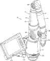
图1是本发明的便携式CMM的前方透视图,其包括一铰接臂以及相关的主机;Fig. 1 is the front perspective view of portable CMM of the present invention, and it comprises an articulated arm and relevant main frame;
图2是图1中的的CMM的后方透视图;Figure 2 is a rear perspective view of the CMM in Figure 1;
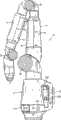
图3是图1中的的CMM的右侧视图(其中主机被去掉);Fig. 3 is the right side view of the CMM among Fig. 1 (wherein main frame is removed);
图3A是图1中的的CMM的右侧视图,其中罩在其中两个长关节(longjoint)上的保护套略有改变;Fig. 3 A is the right side view of the CMM in Fig. 1, wherein the protective cover that covers on two long joints (longjoint) wherein is slightly changed;
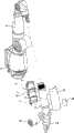
图4是本发明的CMM的局部分解透视图,其中表示出了基座和第一铰接臂部分;Figure 4 is a partial exploded perspective view of the CMM of the present invention showing the base and first articulating arm portion;
图5是本发明的CMM的局部分解透视图,其中表示出了基座、第一铰接臂部分以及局部分解的第二铰接臂部分;5 is a partially exploded perspective view of the CMM of the present invention showing the base, first articulating arm portion, and partially exploded second articulating arm portion;
图6是本发明的CMM的局部分解透视图,其中表示出了基座、第一铰接臂部分以及局部分解的第三铰接臂部分;Figure 6 is a partially exploded perspective view of the CMM of the present invention showing the base, first articulated arm portion, and partially exploded third articulated arm portion;
图7是一局部分解透视图,其中表示出了一对本发明的编码器/轴承机芯,其组装在两个双套筒接头之间;Figure 7 is a partially exploded perspective view showing a pair of encoder/bearing cores of the present invention assembled between two double sleeve joints;
图8是图7中所示的的轴承/编码器机芯和双套筒接头的主视图;Figure 8 is a front view of the bearing/encoder core and double sleeve joint shown in Figure 7;
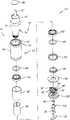
图9是本发明的较短的轴承/编码器机芯的分解透视图;Figure 9 is an exploded perspective view of the shorter bearing/encoder core of the present invention;
图9A是与图9相似的透视图,不同的是表示出了单个读出磁头;Figure 9A is a perspective view similar to Figure 9, but showing a single read head;
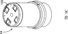
图9B是与图9相似的分解透视图,不同的是表示出了四个读出磁头;Figure 9B is an exploded perspective view similar to Figure 9, except that four read heads are shown;
图9C是与图9B相似的组装后的透视图;Figure 9C is an assembled perspective view similar to Figure 9B;
图9D是与图9相似的分解透视图,不同的是表示出了三个读出磁头;Figure 9D is an exploded perspective view similar to Figure 9, except that three read heads are shown;
图9E是与图9D相似的组装后的透视图;Figure 9E is an assembled perspective view similar to Figure 9D;
图10是图9中所示机芯的剖视图;Figure 10 is a sectional view of the movement shown in Figure 9;
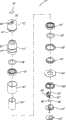
图11是本发明的较长的轴承/编码器机芯的分解透视图;Figure 11 is an exploded perspective view of the longer bearing/encoder core of the present invention;
图11A是与图11相似的分解透视图,不同的是表示出了单个读出磁头;Figure 11A is an exploded perspective view similar to Figure 11, but showing a single read head;
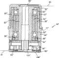
图12是图11中所示机芯的剖视图;Figure 12 is a sectional view of the movement shown in Figure 11;
图12A是图12中所示的机芯剖视图,表示出了可与轴一起旋转的双读出磁头;;Figure 12A is a cross-sectional view of the movement shown in Figure 12, showing dual read heads that rotate with the shaft;
图13是本发明另一个轴承/编码器机芯的分解透视图;Figure 13 is an exploded perspective view of another bearing/encoder movement of the present invention;
图13A是与图13相似的分解透视图,不同的是表示出了单个读出磁头;Figure 13A is an exploded perspective view similar to Figure 13, but showing a single read head;
图14是图13中所示机芯的剖视图;Figure 14 is a cross-sectional view of the movement shown in Figure 13;
图15是本发明一个轴承/编码器机芯以及平衡弹簧的分解透视图;Figure 15 is an exploded perspective view of a bearing/encoder movement and balance spring of the present invention;
图15A是与图15相似的分解透视图,不同的是表示出了单个读出磁头;Figure 15A is an exploded perspective view similar to Figure 15, but showing a single read head;
图16是图15中所示机芯和平衡部件的剖视图;Figure 16 is a cross-sectional view of the movement and balance components shown in Figure 15;
图17是用于本发明的一种直径较大的轴承/编码器机芯的双读出磁头组件的俯视图;Figure 17 is a top view of a dual read head assembly for a larger diameter bearing/encoder core of the present invention;
图18所示的是沿图17中的线18-18所作的剖视图;Shown in Figure 18 is a sectional view taken along line 18-18 among Figure 17;
图19所示的是图17中所示的双读出磁头组件的仰视图;What Fig. 19 shows is the bottom view of the dual read head assembly shown in Fig. 17;
图20所示的是用于本发明的较小的轴承/编码器机芯的双读出磁头组件的俯视图;Figure 20 is a top view of a dual read head assembly for a smaller bearing/encoder core of the present invention;
图21所示的是沿图20中剖面21-21所作的剖视图;What Fig. 21 shows is the sectional view made along section 21-21 in Fig. 20;
图22所示的是图20中所示的双读出磁头组件的仰视图;What Fig. 22 shows is the bottom view of the dual read head assembly shown in Fig. 20;
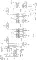
图23A是描述本发明的使用单读出磁头的CMM所采用的电子线路构造的方框图;FIG. 23A is a block diagram illustrating the electronic circuit configuration adopted by the CMM using a single read head of the present invention;
图23B是描述本发明的使用双读出磁头的CMM所采用的电子线路构造的方框图;Fig. 23B is a block diagram describing the electronic circuit configuration adopted by the CMM using the dual read head of the present invention;
图24所示的是本发明的CMM纵向剖视图(其中去掉了基座);What Fig. 24 shows is the CMM longitudinal sectional view of the present invention (wherein removed base);
图24A所示的是图3A中所示的CMM的剖视图;Figure 24A is a cross-sectional view of the CMM shown in Figure 3A;
图25所示的是图24中的一部分的放大剖视图,表示出了图24中的CMM的基座以及第一长关节;Figure 25 is an enlarged cross-sectional view of a part of Figure 24, showing the base of the CMM in Figure 24 and the first long joint;
图25A是表示根据本发明的另一实施例的长关节和短关节之间相互连接状态的视图;25A is a view showing a state of interconnection between long joints and short joints according to another embodiment of the present invention;
图25B所示的是图25A中的一部分的纵向正剖视图;What Fig. 25 B shows is the longitudinal front sectional view of a part in Fig. 25 A;
图26所示的是图24中的一部分的放大剖视图,表示出了第二和第三长关节段(long joint segment);Figure 26 is an enlarged cross-sectional view of a part of Figure 24 showing the second and third long joint segments;
图26A和B所示的是图24A中的一部分的放大剖视图,表示出了第二和第三长关节以及探针;Figures 26A and B are enlarged cross-sectional views of a portion of Figure 24A showing the second and third long joints and the probe;
图27A所示的是一分解侧视图,表示出了本发明的第一短关节/平衡组件;Figure 27A is an exploded side view showing the first short joint/balance assembly of the present invention;
图27B是表示出图27A中的元件的透视图;Figure 27B is a perspective view showing the elements in Figure 27A;
图28是表示本发明的内部平衡部件的正剖视图;Fig. 28 is a front sectional view showing an internal balance member of the present invention;
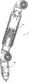
图29是本发明的测量探针的第一实施例的侧向正剖视图;Figure 29 is a side elevational sectional view of a first embodiment of the measuring probe of the present invention;
图29A是本发明的探针的另一实施例的侧视图;Figure 29A is a side view of another embodiment of the probe of the present invention;
图29B是沿图29A的截面29B-29B所作的剖视图;Figure 29B is a cross-sectional view taken along
图29C是用于图29A-B中的一对“执行(take)”或“确认(confirm)”开关的透视图;Figure 29C is a perspective view of a pair of "take" or "confirm" switches used in Figures 29A-B;
图30A-C依次是表示本发明的一体接触探针组件以及转换成硬式探针的的平面视图;30A-C are plan views, in order, showing the integral contact probe assembly of the present invention and conversion to a rigid probe;
图31是本发明的测量探针的另一实施例的侧剖面视图;Figure 31 is a side sectional view of another embodiment of the measurement probe of the present invention;
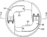
图32是本发明的一体磁性基座的分解透视图;Figure 32 is an exploded perspective view of the integrated magnetic base of the present invention;
图33是图32中的磁性基座的正剖视图;Figure 33 is a front sectional view of the magnetic base in Figure 32;
图34是图32中的磁性固定件的顶部平面视图;Figure 34 is a top plan view of the magnetic mount of Figure 32;
图35是源于Raab的专利’356中的具有双读出磁头的CMM接头(joint)的正剖视图;Figure 35 is a front cross-sectional view of a CMM joint with dual read heads from the '356 patent to Raab;
图36是源于Eaton的专利’148中的具有双读出磁头的CMM接头(joint)的正剖视图;Figure 36 is a front cross-sectional view of a CMM joint with dual read heads from Eaton's '148 patent;
图37是具有第七轴转换器的测量探针的侧视图;Figure 37 is a side view of a measurement probe with a seventh axis transducer;
图38是与图37类似的侧视图,不同的是其中包括一个可拆卸的手柄;Figure 38 is a side view similar to Figure 37, except that a removable handle is included;
图39是图38中的测量探针的端部视图;以及Figure 39 is an end view of the measurement probe in Figure 38; and
图40是图38中的测量探针的正剖视图。FIG. 40 is a front cross-sectional view of the measurement probe in FIG. 38 .
具体实施方式Detailed ways
参见附图1-3,本发明的CMM总体采用标记10表示,CMM10包括一个具有多个连接在一起的、可手动操作的、铰接臂14,该铰接臂的一端连接在基座部分12上,而另一端连接在一测量探针28上。铰接臂14的基本上由两种类型的关节(joint)构成,即长关节(用于作回转运动)以及短关节(用于作铰接运动)。该长关节基本上沿着该铰接臂的轴向或纵向方向布置,而短关节则优选相对于该铰接臂的纵向轴线成90°布置。该长关节和短关节配对出现,这种关节的配对构造通常称之为2-2-2(尽管也可以采用其它的关节的构造形式,例如2-1-2、2-1-3、2-2-3等)。图4-6中表示出了这些关节对中的每一对。Referring to the accompanying drawings 1-3, the CMM of the present invention is generally indicated by
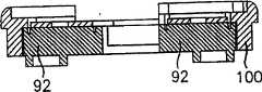
图4表示出了第一关节对的分解视图,即长关节16和短关节18。图4还表示出了基座12的分解视图,包括便携式供电电子装置20、便携式电池组22、磁性固定件24以及两件式基座壳体26A和26B。所有这些元件都会在下面进行更详细的描述。FIG. 4 shows an exploded view of the first joint pair, the long joint 16 and the short joint 18 . 4 also shows an exploded view of
重要的是,需要理解的是,铰接臂14的各种主要部件的直径都是从基座12到探针28逐渐变细。这种逐渐变细的过程是连续的,或者如在图中的实施例所示,这种逐渐变细是不连续的或者是阶梯状的。此外,铰接臂14的每个主要部件都可以通过螺纹连接的方式进行连接,因此可消除现有CMM所涉及到的大量的紧固件。例如,象在后面要阐述的那样,磁性固定件23是采用螺纹连接方式安装在第一长关节16上的。优选的是,这种螺纹是锥形螺纹,它可以进行自我锁定并且可以增加轴向/弯曲刚度。或者,如图25A和25B所示,象在后面要讨论的那样,该铰接臂的主要部件可以具有互补的锥形凸凹端部,这些端部具有相应的凸缘,这种凸缘可以通过螺栓连接在一起。It is important to understand that the diameters of the various major components of the articulating
参见图5,所示的第二组长关节和短关节连接在所述第一组长关节和短关节上。第二关节组包括长关节30和短关节32。和将磁性固定件24安装在长关节16上一样,长关节30也通过螺纹连接方式连接在长关节16的内表面的螺纹上。同样,参见图6,第三关节组包括第三长关节34和第三短关节36。第三长关节34以螺纹连接方式连接在第二短关节32的内表面的螺纹上。象下面将要详细描述的那样,探针28也以螺纹连接方式连接在短关节36上。Referring to FIG. 5 , the second group of long and short joints shown is connected to the first group of long and short joints. The second joint group includes
优选的是,每个短关节18、32以及36都由铸造和/或机械加工过的铝质元件构成,或者也可以采用轻质刚性合金或合成物构成。每个长关节16、30以及34优选都由铸造和/或机械加工过的铝、轻质刚性合金或纤维补强的聚合物构成。三对前述关节对的机械轴(即第一对包括关节对16、18,第二对包括关节对30、32,第三对包括关节对34、36)相对于该基座对齐以便获得平滑一致的机械特性。从基座12到探针28的前述逐渐变细的结构为优选,以便能够增加在负载较大的基座处的刚度,同时在能够通畅使用方面很重要的探针或手柄处的截面较小。如在后面将详细描述的那样,每个短关节的两端上都装有缓冲件38,而每个长关节上都罩有一保护罩40或41。需要理解的是,第一长关节16受到基座壳体26A、26B的保护,该基座壳体所提供的保护和保护罩40、41为第二和第三长关节30、34所提供的保护类型相同。Preferably, each short joint 18, 32, and 36 is constructed of cast and/or machined aluminum elements, or may be constructed of lightweight rigid alloys or composites. Each long joint 16, 30, and 34 is preferably constructed of cast and/or machined aluminum, lightweight rigid alloy, or fiber-reinforced polymer. The mechanical axes of the three aforementioned pairs of joints (i.e. the first pair comprising
根据本发明的一个重要特征,铰接臂的每一关节都采用一种模制的(modular)轴承/编码器机芯,例如如图7和8所示的短机芯42以及长机芯44。这些机芯42、44安装在双套筒接头46、48的开口中。每个套筒接头46、48都包括具有第一凹部或套筒120的第一圆柱延伸部分47以及具有第二凹部或套筒51的第二圆柱延伸部分49。通常,套筒120和51彼此成90°角,不过也可以采用其它相对角结构。短机芯42布置在双套筒接头46和48的每个套筒51中以便构成一种铰接关节(hinge joint),同时长机芯44布置在接头46(见图25)的套筒120中而长机芯44’(见图26)布置在接头48的套筒120中,从而每个都构成一种纵向的回转连接(swivel joint)。模制的轴承/编码器机芯42、44容许独立制造其上安装有该模制的编码器元件的预应力或预加载荷的双轴承机芯。该轴承编码器机芯随后可以固定安装到铰接臂14的外部骨骼部件(即,双套筒接头46、48)上。采用这种机芯的显著优点在于它能够高质量高速地生产铰接臂14的这些复杂的子部件。According to an important feature of the invention, each joint of the articulated arm employs a modular bearing/encoder core, such as the
在此处所述的实施例中,有四个不同的机芯类型,即,用于关节30、34的两个轴向长机芯、一个用于关节16的基座轴向机芯、一个用于短关节18和16的基座机芯(其包括一平衡部件)以及两个用于关节32和36的铰接机芯。此外,与逐渐变细的铰接臂14相一致,最靠近基座的机芯(例如,位于长关节16和短关节18中的机芯)的直径相对具有较小直径的关节30、32、34以及36而言要大些。每个机芯都包括一预加载荷轴承结构和一转换器,在该实施例中,该转换器包括一数字编码器。参见图9和10,现在对位于轴向长关节16中的机芯44进行说明。In the embodiment described here, there are four different movement types, namely, two long axial movements for the
机芯44包括一对由内座套54和外座套56分开的轴承50、52。重要的是轴承50、52上要预加载荷。在该实施例中,这种预加载荷通过座套54、56提供,该座套54、56具有不同的长度(内座套54要比外座套56短大约0.0005英寸),从而在紧固时在轴承50、52上产生一预先选定的预加载荷。轴承50、52采用密封件58进行密封,这些部件构成的该组件可旋转地安装在轴60上。在其上表面处,轴60的末端形成一轴上部壳体62。在轴60和轴上部壳体62之间形成一环形空间63。整个组件被布置在机芯外壳体64内,其中采用内螺母66和外螺母68的组合将该轴60和其轴承组件牢固安装在机芯外壳体64上。需要注意的是,在组装的时候,外壳体64的上部65将被容纳在环形空间63内。可以理解到的是,在对内外螺母66和68进行紧固时对该轴承施加压缩力,从而将上述预加载荷施加到轴承50、52上,并且由于内外间隔套(座套)54、56的长度不同,因此可以施加所需的预加载荷。The
优选的是,轴承50、62是两个成对双联向心推力球轴承。为了获得足够的预加载荷,使得支承面尽可能的平行是很重要的。该平行度会影响到轴承周边上的预加载荷的均匀度。不均匀的载荷会导致极为不均匀的扭矩感觉并且会导致不可预测的径向跳动和降低编码器性能。模块化安装的编码器盘(将在下面进行讨论)的径向跳动会在读出磁头下面导致一种不理想的干涉条纹移位。这种情况会导致编码器角度测量出现重大的误差。而且,这种优选的成对双联向心推力球轴承结构的刚度也与轴承的分离直接相关。轴承相距越远,该组件越有刚性。采用间隔套54、56可以增强该轴承的分离。由于机心外壳64优选为铝质的,因此间隔套54、56优选也采用铝制成并且在长度和平行度方面进行精确加工。因此,温度改变不会导致不均匀的膨胀,这种不均匀的膨胀会影响到该预加载荷。如前所述,通过以一种已知方式设计间隔套54、56的长度方面的差别可以获得该预加载荷。一旦该螺母66、68完全被紧固后,该长度差可以导致一轴承预紧度。使用密封件58可以提供密封轴承,因为轴承的任何污染都会影响到所有旋转运动和编码器的精度以及关节感觉(joint feel)。Preferably, the
尽管机芯44优选包括一对间隔开的轴承,但是机芯44也可以包括单个轴承或三个或更多的轴承。因此,每个机芯至少需要一个轴承,作为最低需要。Although
本发明的连接机芯既可以作无限的旋转运动,或者作为一种选择也可以作有限旋转运动。为了实现有限旋转运动,在壳体64的外表面上的凸缘72上的一个槽70形成了一条容纳一梭子(shuttle)74的圆柱轨道70。该梭子74将行驶在轨道70中直到其抵靠在一可拆卸的梭子止动件为止,该梭子止动件例如旋转止动调节螺钉76,通过该调节螺钉可以阻止旋转运动。旋转运动的转数可以根据需要进行改变。在一优选实施例中,可以将梭子的转数限定为低于720°。此处的旋转梭子止动件的类型在共同转让的美国专利US5611147中有详细的描述,该专利的所有内容以参引的方式包含在本申请中。The linked movement of the present invention is capable of either infinite rotational movement or, alternatively, limited rotational movement. A
如上所述,在另一可替换实施例中,本发明所使用的关节进行无限的旋转运动。在后面一种情况下,采用了一种已知的滑环组件。优选的是,轴60有一中空或轴向孔78,该孔的一端有一个直径较大的部分80。在轴向孔78和80之间形成的台肩上抵靠有一个圆柱形滑环组件82。相对于在该模制连接机芯中提出的该预加载荷轴承组件而言,滑环组件82是不起结构租用的(也就是说,它并不提供任何机械功能,仅仅提供电的和/或信号传递功能)。尽管滑环组件82可以是任何市场上可以购买到的滑环,但是在一优选实施例中,滑环组件82包括可以从United Kingdom Reading,BERKSHRE的IDMElectronics Ltd.公司购买的H系列的滑环。这种滑环尺寸比较紧凑并且具有圆柱形结构,而且可以完美地适用于轴60内的孔80中。穿过轴60的轴向孔80的末端形成孔84,该孔84与槽道86连通,该槽道86的大小和结构可以容纳来自于滑环组件82的电线。该电线由电线盖88固定就位并受到保护,该电线盖88卡装在槽道86和孔84中。这种电线由图10中的标记90示意性地表示。As mentioned above, in another alternative embodiment, the joints used in the present invention perform infinite rotational motion. In the latter case, a known slip ring assembly is used. Preferably,
如上所述,模制机芯44包括一上述预加载荷轴承构件以及一下面将要描述的模制的编码器构件。还是参见图9和10,用于本发明的该优选的转换器包括一模制光学编码器,该编码器具有两中主要部件,即读出磁头92和光栅盘94。在该实施例中,一对读出磁头92布置在一读出磁头连接器板96。该连接器板96安装在一安装板100上。光栅盘94优选(优选采用一种适当的粘合剂)安装在轴60的下部支承表面102上并且与该读出磁头92(该磁头通过板100支承固定)间隔开并且与该读出磁头对齐。一电线箍104和密封盖106为壳体64的下端提供了最外部的遮盖。电线箍104会如图10所示的那样收纳和保持电线90。可以理解到的是,该编码器盘94有在102上涂敷有粘合剂而被固定在轴60上并可随着该轴旋转。图9和10表示出了一种双读出磁头92,不过,可以理解到的是,可以使用两个以上的读出磁头,或者如图9A中所示使用单个读出磁头。图9B-C表示出了安装在一板100中的四个读出磁头92并且以90°的间隔间隔开(尽管采用不同的相对间隔也是合适的)。图9D-E表示出了安装在一板100中的三个读出磁头92并且以120°的间隔间隔开(尽管采用不同的相对间隔也是合适的)。As noted above, the molded
为了同心地对齐盘94,在靠近盘94的位置提供了一个穿过壳体64的孔(未示出)。随后采用一种工具(未示出)将盘94推动到同心对齐位置,在该位置上使得盘94和轴60之间的粘合剂固化以便将盘94锁定就位。随后将孔塞73插入壳体64中的所述孔(未示出)中。To align
重要的是需要指出,该盘94和读出磁头92的位置可以反过来,从而盘94固定在外座套56上而读出磁头92可以与轴60一起旋转。图12A中表示出了这样的实施例,其中板96’(通过粘合剂)固定在轴60’上以便与其一起旋转。一对读出磁头92’固定在板96’上并因此和轴60’一起旋转。盘94’布置在一支承件100’上,该支承件100’固定在外壳64’上。在任何情况下,可以理解到的是,无论是盘94还是读出磁头92都可以安装成与轴一起旋转。重要的是盘94和读出磁头92要布置在一机芯(或接头)中以便在维持光学连通的同时可以彼此相对旋转。优选的是,在本发明中所采用的旋转编码器比在美国专利US5486923以及US5559600中披露的那个要小,这两个专利的所有内容都通过参引的方式包含在本申请中。这种模制编码器可以从MicroE Systems公司购买到,其商品名称为Pure Precision Optics。这些编码器都以物理光学为基础检测衍射级之间的干涉,从而从一插入干涉条纹中的光电检测器阵列中生成近乎完美正弦信号。采用电子学的方法对该正弦信号进行内插值以便能够检测到仅仅一小部分光学条纹的位移。It is important to note that the positions of the
采用一种激光源,首先采用一透镜使该激光束成为平行光束,随后通过一小孔进行筛分(sized)。该筛分后的平行激光束穿过一光栅,该光栅使得光衍射成具有0th的离散级(discrete order)以及受到光栅结构(gratingconstruction)抑制的所有均匀级(even order)。由于该0级受到抑制,在第三分支级()之外存在一个区域,在该区域内只有±1st级相互交迭形成一近乎纯粹的正弦干涉。在该区域内布置一个或多个光电检测器阵列(读出磁头),并且当光栅和检测器之间存在相对运动时该光电检测器阵列产生四个信道的几乎纯粹的正弦输出量。将输出量进行电子学放大、规格化并内插到理想的分辨水平(level of resolution).Using a laser source, a lens is used to first make the laser beam into a parallel beam, which is then sized by passing through a small hole. The screened parallel laser beam passes through a grating that diffracts the light into a discrete order with 0th and all even orders suppressed by the grating construction. As the 0 order is suppressed, there is a region outside the third branch stage ( ) where only ±1st orders overlap each other forming a nearly pure sinusoidal interference. One or more photodetector arrays (readout heads) are arranged in this area and produce four channels of almost purely sinusoidal output when there is relative motion between the grating and detector. The output is electronically amplified, normalized and interpolated to the desired level of resolution.
对该编码器结构的简化产生了几个优于现有光学编码器的优点。仅仅采用一个激光源及其平行校准光学器件、衍射光栅以及一检测器阵列就可以进行测量。相对于较为粗笨的现有普通编码器而言,这就使得本发明的编码器装置显得极为紧凑。此外,该光栅和干涉条纹运动(fringe movement)之间的直接关系减弱了该编码器对外界环境所引起的误差的的敏感性,而现有的装置就易于受到这种误差的影响。而且,由于该干涉区域较大,并且可以在该区域的任何位置获得几乎正弦干涉,因此,对准直容差(alignmenttolerance)的要求远比现有编码器在这方面的要求宽松得多。The simplification of the encoder structure yields several advantages over existing optical encoders. Measurements can be performed using only a laser source with its collimating optics, a diffraction grating and a detector array. This makes the encoder device of the present invention extremely compact compared to the relatively bulky existing ordinary encoders. Furthermore, the direct relationship between the grating and fringe movement reduces the sensitivity of the encoder to environmental induced errors to which existing devices are susceptible. Moreover, since the interference region is large and almost sinusoidal interference can be obtained anywhere in the region, the requirements for alignment tolerance are much looser than those of existing encoders in this regard.
前述光学编码器的一个显著的优点是,对读出磁头相对于该编码器盘的偏离位置和距离的精度或距离和位置的严格程度要低得多。这样就能获得一种高精度的旋转测量以及一种易于组装的包装。采用这种“具有几何容忍性(geometry tolerant)”的编码器技术使得CMM10的成本显著降低并且使得制造更为容易。A significant advantage of the aforementioned optical encoders is that the accuracy or distance and position of the read head offset position and distance relative to the encoder disk is much less critical. This results in a high-precision rotation measurement and an easy-to-assemble package. Using this "geometry tolerant" encoder technology makes the
人们将会认识到,尽管上述优选实施例含有一种光盘(optical disk)94,但是本发明的优选实施例还可包括任何光学干涉条纹图案,该图案使得该读出磁头能够检测到相对运动。如在此所使用的那样,这种干涉条纹图案表示出了用来测量运动的光学元件的任何周期阵列。这些光学元件或干涉条纹图案可以安装到如上所述的旋转或固定的盘上,或者可以储存、固定或布置或安置在该机芯的任何相对运动的部件(例如轴、轴承或壳体)上。It will be appreciated that although the preferred embodiment described above includes an
实际上,该读出磁头以及相关的周期阵列或图案并不必定需要完全基于(如上所述的)光学器件。广义上来说,该读出磁头还可以读出(或检测到)许多其他可测量的数量或特性的许多其他的周期图案,这些可测量的数量或特性可以用来检测运动,例如通常为旋转运动。这些其它可测量的特性可以包括例如反射率、不透明性、磁场、电容、感应系数或表面粗糙度(注意,表面粗糙度图案可以采用具有相机例如CCD相机这种形式的读出磁头或传感器来读出)。在这些情况下,读出磁头将会测量出例如磁场、反射率、电容、感应系数、表面粗糙度等的周期变化。如在此所使用的术语那样,术语“读出磁头”表示任何采用一种正如一优选实施例那样的光学读出磁头分析可测量的数量或特性的传感器或转换器以及相关的电子学器件。当然,由读出磁头读出的周期图案可以位于任何表面上,只要读出磁头和周期图案之间存在相对运动(通常为旋转运动)。周期图案的一些例子包括以图案形式沉积在一旋转或固定部件上的磁性的、感应的或电容性的媒介。而且,如果表面粗糙度为待读出的该周期图案,就没有必要沉积或提供一独立的周期图案,因为使用任何与该相关的读出磁头(可能为一架相机,例如为CCD相机)相连通的部件上的该表面粗糙度就可以了。In practice, the read head and associated periodic array or pattern need not necessarily be based entirely on optics (as described above). Broadly speaking, the read head can also read (or detect) many other periodic patterns of many other measurable quantities or properties that can be used to detect motion, such as typically rotational motion . These other measurable properties can include, for example, reflectivity, opacity, magnetic field, capacitance, inductance, or surface roughness (note that the surface roughness pattern can be read using a readout head or sensor in the form of a camera, such as a CCD camera). out). In these cases, the read head will measure periodic variations such as magnetic field, reflectivity, capacitance, inductance, surface roughness, etc. As the term is used herein, the term "read head" means any sensor or transducer and associated electronics that employs an optical read head as a preferred embodiment to analyze a measurable quantity or property. Of course, the periodic pattern read by the read head can be on any surface as long as there is relative motion (usually rotational motion) between the read head and the periodic pattern. Some examples of periodic patterns include magnetic, inductive or capacitive media deposited in a pattern on a rotating or stationary component. Furthermore, if the surface roughness is the periodic pattern to be read, there is no need to deposit or provide a separate periodic pattern, since any associated read head (possibly a camera, such as a CCD camera) is used This surface roughness on common parts is sufficient.
如上所述,图9和10表示的是用于轴向长关节16的模制轴承和编码器机芯的一些例子。图11和12所示的是用于轴向长关节30和34的轴承和编码器机芯。这些机芯组件基本上都与图9和10中所示的相似并且因此标记为44’。从这些图可以明显地得出区别于机芯44的一些细微的区别,这些区别例如涉及电线盖/罩88’结构不同的、电线箍/套104’、106’略有不同以及外壳体64’的上端处的凸缘72’的位置略有不同。而且,壳体64’和轴上部壳体62之间的凸缘是向外展开的。当然,图11和12中所示的各种部件的相对长度也与图9和10中所示的情况不同。由于所有这些部件基本上都相似,因此这些部件都采用相同的数字加上一个符号“‘”来指代。图11A与图11相似,不同的是表示出的是具有单个读出磁头的实施例。As mentioned above, FIGS. 9 and 10 show some examples of molded bearing and encoder cores for long axial joint 16. As shown in FIG. Figures 11 and 12 show the bearing and encoder movement for the long
参见图13和14,所示的是短铰接关节(short hinge joint)32和36中的轴承和编码器机芯的分解剖视图。如图11和12中的轴向长关节44’所示,用于短铰接关节32和36的机芯基本上与上面详细描述的机芯44类似,因此这些机芯的元件标记为44″,并且相似的元件采用原来的竹子加上符号“″”来表示。人们将会理解到,由于机芯44″将用于短关节32、36,因此不需要滑环组件,因为该电线将由于这些关节的铰接运动而简单地穿过该轴向孔78″、80″。图13A与图13类似,不同的是表示的是一单读出磁头的实施例。13 and 14, shown are short hinge joints (short hinge joint) 32 and 36 in the bearing and encoder movement exploded cross-sectional view. The movements used for the short articulation joints 32 and 36 are substantially similar to the
最后,参见图15和16,短铰接关节18的模制轴承/编码器机芯图示为108。可以认识到的是,基本上机芯108的所有部件都与机芯44、44’以及44″中的部件相似或相同,其中重要的不同在于包含有一平衡组件。该平衡组件包括一平衡弹簧110,该弹簧套装在壳体64″上并以一种下面将会参照图26-28进行描述的方式为CMM10提供一种重要的平衡功能。图15A与图15相似,但是所示的是一单读出磁头实施例。Finally, referring to FIGS. 15 and 16 , the molded bearing/encoder core of the short articulation joint 18 is shown at 108 . It will be appreciated that substantially all parts of
如上所示,在一优选实施例中,在该编码器中可以采用一个以上的读出磁头。可以理解到的是,可以通过由于所施加的负载而引起的盘的径向跳动或径向运动而进行编码器的角度测量。已经确定的是,两个彼此成180°布置的读出磁头会导致径向跳动,该径向跳动会在每个读出磁头内产生抵消效应。对这些抵消效应求平均值获得一最终的“免除的(immune)”角度测量值。因此采用两个读出磁头以及合成误差抵消会导致出错的可能性减小并且获得更为精确的编码器测量值。图17-19分别表示的是用于较大直径的机芯中的双读出磁头实施例的仰视图、剖视图以及俯视图,该大直径的机芯例如可在关节16和18(也就是最靠近基座的那些关节)中找到。因此,一机芯端盖100上安装有一对电路板96,每个电路板96上都具有一采用机械方式安装在其上的读出磁头92。该读出磁头92优选布置成彼此间隔开180°,以备由所述盘的径向跳动或径向运动所导致的误差抵消。每个电路板96都还包括一用于将该电路板96连接到下面将要进行说明的内部总线和/或其他电线上的连接器93。图20-22所示的部件基本上与图17-19中所示的部件相同,其中主要的区别是有一较小直径的机芯端盖100。该较小直径的双读出磁头实施例上连接有关节30、32、34以及36的所述较小直径机芯。As indicated above, in a preferred embodiment, more than one read head may be used in the encoder. It will be appreciated that the angular measurement of the encoder can be made by the radial runout or radial movement of the disc due to the applied load. It has been determined that two read heads arranged at 180° to each other cause radial runout which produces a canceling effect within each read head. These canceling effects are averaged to obtain a final "immune" angle measurement. Thus using two read heads and resulting error cancellation results in less error prone and more accurate encoder measurements. Figures 17-19 represent bottom, cross-sectional and top views, respectively, of an embodiment of a dual read head for use in a larger diameter movement such as can be found at
优选的是,采用至少两个读出磁头(或更多磁头,例如图9D-E中所示的三个读出磁头以及图9B-C中所示的四个读出磁头)也可被多种普通的坐标测量机所采用,从而显著地降低该测量机的制造成本和复杂性。例如,美国专利US5794356(以下简称为专利‘356,并以参引方式包含在本申请中)中所描述的一种坐标测量机中的每个关节的构造都相对简单,每个关节都包括第一壳体和第二壳体,该第一壳体保持固定并带有一关节半片(joint half),而第二壳体保持固定并具有第二关节半片,该第一和第二壳体具有预加载荷轴承,该轴承使其能够相对旋转。第一壳体固定一装好的编码器而第二课题包括一轴向布置的内轴,该内轴延伸到第一壳体中并与从该装好的编码器中凸出的该编码器轴相匹配。该现有的装好的编码器要求没有负载施加在其上,并且尽管该内轴的轴线与该装好的编码器的轴线对的不是太齐,但是第二壳体的运动要精确地传递到该编码器上以便维持较高精度的旋转测量。为了适应在轴向不对齐方面的制造公差,就需要在该编码器轴和该内轴之间连接一个特殊的联轴装置。这种构件如在Raab的专利‘356中的图7所示。Preferably, using at least two read heads (or more heads, such as the three read heads shown in FIGS. 9D-E and the four read heads shown in FIGS. 9B-C ) can also be multiplied. A common coordinate measuring machine, thereby significantly reducing the manufacturing cost and complexity of the measuring machine. For example, the structure of each joint in a coordinate measuring machine described in US Patent No. 5,794,356 (hereinafter referred to as patent '356 and incorporated in this application by reference) is relatively simple, and each joint includes a A shell and a second shell, the first shell remains fixed and has a joint half (joint half), and the second shell remains fixed and has a second joint half, the first and second shells have predetermined Loaded bearings that enable relative rotation. The first housing holds a mounted encoder and the second subject comprises an axially arranged inner shaft extending into the first housing and projecting from the mounted encoder Axes match. The existing mounted encoder requires no load to be applied to it and the movement of the second housing is accurately transmitted despite the misalignment of the axis of the inner shaft with the axis of the mounted encoder to this encoder in order to maintain a high precision rotation measurement. To accommodate manufacturing tolerances in axial misalignment, a special coupling is required between the encoder shaft and the inner shaft. Such a structure is shown in Figure 7 of the '356 patent to Raab.
对比而言,图35所示的是一种变化结构,Raab的专利‘356中CMM的连轴装置和装好的编码器被去掉并采用编码器盘96和端盖100替代。在此,两个关节彼此呈90°布置,每个关节具有第一壳体420和第二壳体410。内轴412从第二壳体420延伸到第一壳体410中。如图所示,编码器盘96例如采用粘合剂安装在该内轴412的末端,而端盖100固定在第一壳体420内。不过,可以理解的是,编码器盘96可以固定在第一壳体420内并且端盖100可以固定到内轴412上而不会影响到该关节的运转。In contrast, a variation is shown in FIG. 35 in which the shaft coupling and installed encoder of the CMM of Raab '356 are removed and an
如上所述,采用两个(或更多的)读出磁头以及合成误差抵消会导致出错的可能性减小并且获得更为精确的编码器测量值,尽管轴线对得不是太齐。此外,光栅和干涉条纹运动之间的直接关系减弱了该编码器对外界环境引起的误差的敏感性,而现有装置则易于受到该误差的影响。而且由于该干涉区域较大,并且在该区域内的每个位置都可以获得几乎正弦干涉,因此对对齐公差的要求要比前述现有编码器的要求宽松得多。As mentioned above, the use of two (or more) read heads and the resulting error cancellation results in less error potential and more accurate encoder measurements despite misalignment of the axes. Furthermore, the direct relationship between the grating and fringe motion reduces the encoder's sensitivity to environmental induced errors to which existing devices are susceptible. And since this interference area is large and almost sinusoidal interference is obtained at every position within this area, the requirements for alignment tolerances are much looser than those of the aforementioned prior art encoders.
在另一实例中,Eaton的美国专利US5829148(以下简称为Eaton的专利’148,其以参引的方式包含到本申请中)描述了一种现有CMM,其中一装好的编码器通过提供主旋转轴承而形成每个关节的一体部分,因此不需要对如上所述的Raab专利‘356中的轴向不对齐情况进行补偿。不过,由于该编码器提供了主旋转轴承,因此重要的是该编码器在结构上具有抗震性(rugged)并且能够经受各种负载而不会影响到其性能。这就增加了该编码器的成本和粗笨程度。这种结构如Eaton的专利’148中的图4所示。In another example, Eaton's U.S. Patent No. 5,829,148 (hereinafter referred to as Eaton's patent '148, which is incorporated herein by reference) describes an existing CMM in which an installed encoder is provided by providing The main swivel bearings form an integral part of each joint, so there is no need to compensate for axial misalignment as described above in the Raab '356 patent. However, since the encoder provides the main rotary bearing, it is important that the encoder is structurally rugged and able to withstand various loads without affecting its performance. This increases the cost and bulkiness of the encoder. Such a structure is shown in Figure 4 of the Eaton '148 patent.
对照而言,图36所示的是一种变化结构,其中,Eaton的专利’148中的该装好的编码器和其中一个关节的连接轴被去掉并由端盖100和编码器盘96替代。在此,第一壳体470保持端盖100并且通过轴承472保持第二壳体460的内轴462。内轴462延伸到末端靠近端盖100,并且编码器盘96例如采用粘合剂安装在该内轴462的末端。如在图35中所示的实施例一样,采用两个(或更多的)读出磁头会显著地降低该关节的成本和复杂性同时不会损失精度。In contrast, FIG. 36 shows a variation in which the installed encoder and the connecting shaft of one of the joints in Eaton's '148 patent are removed and replaced by an
回头看图23A,其所示的是用于图9A、11A、13A以及15A中的单读出磁头实施例的电子线路的方框图。可以理解到的是,CMM10优选包括一外部总线(优选为USB总线)260以及一内部总线(优选为RS-485)261,该外部总线设计成可扩展的,以便用于多个编码器以及一从外部安装的扶手(rail)或附加的旋转轴,例如第七轴。该内部总线优选与RS485相一致,并且该总线优选设置成可以以一种与用于传送来自于一便携式CMM铰接臂中的转换器的数据的串行网络相同的方式用作一个串行网络,该CMM铰接臂披露在在共同转让的美国专利US6219928(其全部内容以参引方式包含在本申请中)中。Referring back to FIG. 23A, shown is a block diagram of the electronics for the single read head embodiment of FIGS. 9A, 11A, 13A, and 15A. It can be understood that the
参见图23A,可以理解的是,在每个机芯中的每个编码器都与一编码器板相连。关节16中的机芯的编码器板被布置在基座12中并且在图25中被标记为112。关节18和30的编码器在一双编码器板上受到处理,该双编码器板位于第二长关节30中并且在图26中被标记为114。图26也表示了一种相似的双编码器板116,用于关节32和34中的编码器,编码器板116位于如图26所示的第三长关节34中。最后,该端部编码器板118如图24所示位于测量探针手柄28内并且被用来处理短关节36中的编码器。这些编码器板114、116以及118中的每一个都连接有一热电偶以便提供由于温度瞬变导致的热补偿。每个编码器板112、114、116以及118都包含有嵌入式模数转换,编码器计数以及串行端口通信(serial port communication)。每个编码器板都具有可读取编程的快速存储器以便能够将操作数据存储在本地。主处理器插接板112也是可以通过外部USB总线260编程的区域(field)。如上所述,该内部总线(RS-485)261设计成可扩展式的以便用于更多的编码器,该编码器也包括一从外部安装的扶手(rail)和/或第七旋转轴。已经设置了一轴孔以便为内部总线提供诊断。由于外部USB通信协议的容量的原因,可以将多个这些附图中表示为10的CMM可以连接到一单一应用场合(single applicaiton)。而且也可以由于完全相同的原因而将多个应用连接到单一CMM10上。Referring to Figure 23A, it will be appreciated that each encoder in each movement is associated with an encoder board. The encoder plate of the movement in the joint 16 is arranged in the
优选的是,每个编码器板112、114、116以及118都包括一16位的数字信号处理器,例如可以从Motorola购买的标识为DSP56F807的处理器。该单一处理部件将多种处理特征(这些特征包括串行通信、积分译码、A/D转换器以及在板存储器)结合起来,因此能够减少每个编码器板所需的芯片的总数。Preferably, each
根据本发明的另一个重要特征,每个编码器都与一具有个性化标识的芯片120相连。该芯片用来标识每个个别编码器并因此标识出每个个别的轴承/编码器模制机芯,从而能够方便而快速地进行质量控制、测试以及修复。According to another important feature of the invention, each encoder is connected to a
图23B是一个与图23A相似的电子线路方框图,但是所示的是图10、12、14以及16-22中的双读出磁头实施例。Figure 23B is an electrical block diagram similar to Figure 23A, but showing the dual read head embodiment of Figures 10, 12, 14 and 16-22.
下面将参考图24-26对在该铰接臂14中每个机芯的组件进行描述(注意,图24所示的铰接臂14没有基座12。还有,图24-26采用了图9A、11A、13A以及15A中所示的单读出磁头实施例)。如图25所示,第一长关节16包括一相对较长的机芯44,该机芯的上端被插进双套筒接头46的一圆柱形套筒120中。机芯44通过适当的粘合剂被牢固地固定在套筒120中。该机芯44的相对的下端被插进一延伸管(extension tube)中,在该实施例中,延伸管可以是铝质套管122(但是套管122也可以包括一种刚性合金或复合材料)。机芯44再次采用适当的粘合剂固定在该套管122内。该套管122的下端包括一较大的外直径部分124,该部分上具有内螺纹126。该螺纹向外呈锥形并且设置成可以与位于磁性固定件壳体130上的向内呈锥形的螺纹128(清楚表示在图4中)进行螺纹配合。如上所述,CMM10的所有关节都采用这种锥形螺纹相互连接。优选的是,该锥形螺纹为能够自我紧固的美国标准锥管螺纹(NPT)型螺纹,因此不需要锁定螺母或其它的紧固装置。该螺纹还容许并应包括螺纹锁定剂(thread locking agent)。The assembly of each movement in this articulated
参见图26,与第一长关节16一样,长机芯44’是采用粘合剂固定在双套筒接头46’的圆柱形开口120’中的。该机芯44’的外壳体64’包括一由凸缘72’的下表面形成的台肩132。该台肩132支承圆柱形延伸管134,该延伸管设置并套在外壳体64’的外表面上。延伸管用于这些关节中以便形成一安装到一带螺纹的部件上的长度可变的管。延伸管134因此从外壳体64’的底部向外延伸并其中已经插入了一螺纹套管136。采用适当的粘合剂将该外壳体64’粘接到延伸管134上以及将套管136和延伸管132粘接在一起。套管136的末端为一锥形部分,该锥形部分上具有外螺纹138。该外螺纹以螺纹连接方式与位于连接件142上的内螺纹140相配合,该连接件在这之前已经采用粘接方式固定在了双套筒接头48的开口144中。优选的是,延伸管134采用复合材料构成,例如一种合适的碳纤维复合材料,而螺纹套管136由铝构成,以便与该双套筒关节48的热学特性相匹配。可以理解到的是,PC斑114紧固在一支承件146上,该支承件又固定在双套筒关节支承件142上。Referring to Fig. 26, like the first long joint 16, the
除了上述螺纹连接外,一个或多个或者所有关节都可以采用如图25A-B中所示的螺纹紧固件进行相互连接。不是图26中的螺纹套管136而是图25B中的套管136’具有光滑的锥形端部137,该锥形端部容纳在一具有互补锥形套筒的支承件142’中。凸缘139沿着周边从套筒136’向外延伸,该凸缘上具有一批螺栓孔(在该实例中为6个螺栓孔),穿过这些螺栓孔安装有螺栓141。螺栓141沿着套筒支承件142’的上表面以螺纹连接方式安装在相应的螺栓孔中。延伸管134’套装在图26中所示的实施例中的套管136’上。这些关节这种互补的锥形凸凹互连相对于现有技术来说改善了连接界面。In addition to the threaded connections described above, one or more or all joints may be interconnected using threaded fasteners as shown in Figures 25A-B. Instead of the threaded
还是参见图26,第三长关节34的长机芯44″采用与长关节30的机芯44’相似的方式固定到铰接臂14上。也就是说,机芯44″的上部采用粘合方式固定到双套筒关节46″的一开口120″中。延伸管148(优选采用在针对管134进行说明时所描述的复合材料构成)套装在外壳体64″上并且由其上向外延伸,以便容纳一配合套管150,该配合套管以粘合方式固定在延伸管148的内径上。配合套管150的末端形成一锥形部分,该锥形部分上具有外螺纹152并且与双套筒关节支承件154上的互补内螺纹153相配合,该支承件154之前已经粘接在了双套筒关节148’内的一圆柱形套筒156上。印刷电路板116同样采用PCB支承件146’连接到该双套筒关节上,该PCB支承件146’固定在双套筒关节支承件154上。Still referring to Fig. 26, the
如针对图7和8所述,在图13和14中的短关节机芯44’以及图15中的机芯108简单地布置在两个双套筒关节46、48之间并且采用一种合适的粘合剂固定在该双套筒关节内。因此,该长短机芯都能较容易地彼此成直角(如果需要的话可以成直角之外的任何角度)连接起来。As described for FIGS. 7 and 8 , the short
如上所述的模制轴承编码器机芯构成了如在前述Raab的专利’356以及Eaton的专利’148中所示的便携式CMM的一种重要的技术进步。这是因为,该机芯(或该机芯的外壳)实际上形成了每个关节的结构元件,每个关节组成了该铰接臂。在此所使用的术语“结构元件”的意思是该机芯的表面(例如机芯壳体)刚性地连接在铰接臂的其它结构元部件上,以便在不使该铰接臂变形的情况下(或最多只能变形最小)传递旋转运动。这和普通便携式CMM(例如在Raab的专利’356以及Eaton的专利’148中所披露的那种)形成对比,其中,需要有单独和截然不同的关节元件和传递元件,因为该旋转编码器是关节元件的一部分(但是不是传递元件的一部分)。实质上,本发明不需要单独的传递元件(例如传递部件),因为关节元件和传递元件的功能够被整合到了一个单一模制部件(即,机芯)中。因此,与由独立和截然不同的关节和传递元件构成的铰接臂不同,本发明采用了一种由长短关节元件的组合体(即,机芯)构成的铰接臂,这些长短关节都是该铰接臂的结构元件。这相对现有技术来说可获得更好的效率。例如,在专利’148以及专利’582中一关节/传递部件组合体中所使用的轴承的数量为四个(关节中有两个轴承而传递部件中有两个轴承),而奔本发明中的模制轴承/转换器机芯可以使用最少一个轴承(尽管使用两个轴承为优选)并且依然能够实现相同的功能(尽管可以采用一种不同且改进的方式)。The molded bearing encoder movement as described above constitutes an important technological advance over portable CMMs as shown in the aforementioned Raab '356 patent and Eaton '148 patent. This is because the movement (or the casing of the movement) actually forms the structural element of each joint that makes up the articulated arm. The term "structural element" as used herein means that the face of the movement (e.g. movement casing) is rigidly attached to other structural elements of the articulated arm so that without deforming the articulated arm ( Or at most only deformed minimally) to transmit rotational motion. This is in contrast to common portable CMMs (such as those disclosed in Raab's '356 patent and Eaton's '148 patent) where separate and distinct articulation and transmission elements are required because the rotary encoder is Part of the joint element (but not part of the transmission element). In essence, the invention does not require a separate transmission element (eg a transmission part), since the functions of the articulation element and the transmission element can be integrated into a single molded part (ie the movement). Thus, instead of an articulated arm made up of separate and distinct joints and transmission elements, the present invention employs an articulated arm made up of a combination of long and short joint elements (ie, the movement) that are the articulation Structural elements of the arm. This achieves better efficiency than the prior art. For example, the number of bearings used in a joint/transfer member combination in the '148 and '582 patents is four (two bearings in the joint and two bearings in the transfer member), whereas in the present invention The molded bearing/converter core can use as few as one bearing (although using two is preferred) and still perform the same function (though in a different and improved way).
图24A以及26A-B是一些与图24-26相似的剖视图,但是表示出的是图10、12、14以及16-22中所示的双读出磁头实施例,并且还是图3A中所示的CMM10’的剖视图。Figures 24A and 26A-B are cross-sectional views similar to Figures 24-26, but showing the dual read head embodiment shown in Figures 10, 12, 14 and 16-22, and also shown in Figure 3A Cutaway view of the CMM10'.
该铰接臂14的全长和/或各个臂段可以根据其所要使用的场合而变化。在一实施例中,该铰接臂的全长大约为24英寸并提供大约0.0002到0.0005英寸数量级的测量值。该铰接臂的尺寸和测量精度提供了一种能够较好地适应采用典型的手动工具例如千分尺、高度计、卡尺等就能立即实现测量的便携式CMM。当然,铰接臂14可以具有较小或较大的尺寸和精度等级。例如,较大的铰接臂的全长为8英尺或12英尺,并且相应的测量精度为0.001英寸,因此能够用于最实时的检查用途或用于逆向工程。The overall length of the articulated
CMM10还可以与安装在其上的控制器一起使用,该控制器用于执行一个如在前述专利US5978748以及美国专利申请NO.09/775226中所披露的相对简单化的可执行程序;或者CMM10可以与一相对复杂的程序或主机172一起使用。The
参见图1-6以及24-26,在一优选实施例中,长关节和短关节中的每一个都受到一弹性体缓冲器或罩的保护,该缓冲器或罩所起的作用是限制较高冲力力并提供一种具有人机工程学的舒适抓握部位(以及一种从美观上来说令人感觉舒服的外观)。长关节16、30以及34都受到可更换的硬质塑料(例如ABS)罩的保护,该硬质塑料罩起到一种防冲击和磨损的保护装置的作用。对于第一长关节16,该可更换的硬质塑料罩可以形成两件式基座壳体26A以及26B,如图4中所示。长关节30以及34每个都受到一对罩壳件40和41(如图5和6所示)保护,该队罩壳件可以采用适当的螺钉以蛤壳形式紧固在一起以便形成一个保护套。可以理解的是,在一优选实施例中,用于每个长关节30和34的该可更换的硬质塑料罩都分别包围着该优选为复合材料(碳纤维)的延伸管134和138。Referring to Figures 1-6 and 24-26, in a preferred embodiment, each of the long and short joints is protected by an elastomeric bumper or cover that acts to limit the High impact and provides an ergonomically comfortable grip (and an aesthetically pleasing look). The
优选的是,其中一个罩,例如罩部分41,包括一一体模制在其中的倾斜的支承柱166,该支承柱限制该铰接臂的肘部处的旋转,从而防止在静止状态下探针28碰撞到基座12。这在图3、24以及26中显示的最为清楚。可以理解到的是该支承柱166因此会限制不必要的冲击和磨损。Preferably, one of the covers, such as
如将要针对图29和31所描述的那样,探针28还可以包括一可更换的塑料保护罩,该保护罩采用一种硬质塑料材料制成。As will be described with respect to FIGS. 29 and 31, the
图3A、24A以及26A-B所示的是可替换的保护套40’、41’,这些保护套也具有蛤壳式构造,不同的是它们采用夹板(strap)或弹簧夹167而不是螺纹紧固件来固定就位。Figures 3A, 24A, and 26A-B show alternative protective sleeves 40', 41' which also have a clamshell construction, except that they use straps or
每个短关节18、32以及36都包括一对弹性体(例如热塑性橡胶,例如SANTOPRENE &COMMAT)缓冲器38,和前面所述的并在图1-3以及5-6中清楚表示的一样。缓冲器38可以采用一种螺纹紧固件、适当的粘合剂或采用任何其它适当的方式安装。弹性体或橡胶缓冲器38将限制较高的冲击力并提供具有美感令人愉快并且具有人机工程学的舒适的握持部位。Each short joint 18, 32 and 36 includes a pair of elastomeric (e.g. thermoplastic rubber, eg SANTOPRENE & COMMAT)
前述保护罩40、41、40’、41’以及缓冲器38都可以方便地进行更换(基座壳体26A、26B也一样)并且使得铰接臂14能够在不影响CMM10的机械性能的情况下快速而廉价地进行整修。The aforementioned
还是参见图1-3,基座壳体26A、26B包括至少两个圆柱形轴毂(boss),用来安装如图3中的168处所示的一个球体。该球体可以用来安装夹子型的计算机夹持器170,噶夹持器又支承着一便携式或其他计算机装置172(例如所述的“主机”)。优选的是,圆柱形轴毂设置在该基座壳体26A、B的任意一侧,使得该球体和计算机夹持器可以安装在该CMM的任意一侧。Still referring to FIGS. 1-3 , the
现在参见图15、16、27A、B以及28来描述用于CMM10的该优选的平衡部件。通常,此处所描述的便携式CMM都已经采用了一种从外部安装的螺旋弹簧,该螺旋弹簧以一种悬臂支架的形式独立地安装在铰接臂的外侧以便用作一平衡部件。对比而言,本发明采用一种完全构成一体的内部平衡部件,该平衡部件使得该铰接臂的整个外部轮廓减小。通常,现有平衡部件都是在平衡机构中采用一种卷绕螺旋弹簧。但是,根据本发明的一个重要的特征,该平衡部件采用的却是一种采用机器加工出来的螺旋弹簧(与卷绕螺旋弹簧相对)。图16和27A-B中所示的是这种采用机器加工出来的弹簧110,并且该弹簧110采用单个金属(钢质)圆柱形成,该金属圆柱通过机器加工形成一对位于该螺旋的相对末端的相对较宽的环174、176以及一些构成无效簧圈174、176之间的中间簧圈的相对较窄的环。可以理解到的是,该较宽的无效簧圈174、176分别与轴62’的侧表面180以及壳体64″的侧表面182相啮合,由此防止弹簧110横向运动。较宽的坚固的无效簧圈174、176起到一个抗扭曲装置的作用并且提供了优于现有卷绕弹簧的功能。无效簧圈174优选包括一对锁定柱184、186(尽管可以只用一个锁定柱)而无效簧圈176包括一个锁定柱(locking post)188。Referring now to FIGS. 15, 16, 27A, B, and 28, the preferred counterbalance component for the
参见图27B,每个双套筒关节46、48都包括如在标记190和191处所示的凹槽,用于容纳相应的锁定柱184、186或188。参见图28,尽管锁定柱184、186会以固定状态保持在双套筒关节48的适当凹槽内,但是锁定柱188的位置是可以改变的以便使得弹簧110上的整个卷紧度最佳化并提供最有效的平衡力。这可以采用一种螺纹孔192来实现,该螺纹孔内安装有螺钉194。如图28所示,可以对螺钉194进行操作使其与锁定柱188接触并在圆周方向上沿着内部导槽196逆时针方向推动该锁定柱188,如图27B所示,该内部导槽与锁定柱的进入凹槽190垂直。优选的是在工厂中就将螺钉194布置在使得弹簧110最佳化的位置。Referring to FIG. 27B , each double sleeve joint 46 , 48 includes a recess as indicated at 190 and 191 for receiving a corresponding locking
可以理解到的是,在使用该铰接臂14的过程中,该编码器/轴承机芯108将会起到一铰接关节的作用,并且一旦被插入并采用粘接方式固定在双套筒关节46、48的套筒中时,该锁定柱184、186以及188将会被锁定在其相应的凹槽内。当套筒关节48(经过机芯108的铰接关节)相对套筒关节46旋转时,该弹簧110就会卷紧。当需要套筒关节48旋转回到其原始位置时,该弹簧110的卷绕力就会放松而提供所需的平衡力。It will be appreciated that during use of the articulated
在需要颠倒安装铰接臂14时,例如安装在磨床、横梁或天花板上事4,弹簧110的方位同样可以倒过来(或反过来)以便能获得必要的平衡所需的适当方位。When it is desired to mount the articulated
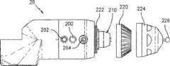
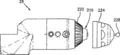
下面参见图29和30A-C来描述测量探针28的一优选实施例。探针28包括一壳体196,该壳体内有内部空间198,用于容纳印刷电路板118。可以理解到的是,壳体196构成上述类型的双套筒关节并且包括套筒197,在该套筒中粘接到一支承部件199,该支承部件用于支承电路板118。优选的是,手柄28包括两个开关,即执行(take)开关200以及确认(confirm)开关202。这些开关由操作者用来在操作过程中(通过执行开关200)进行测量并(通过确认开关202)确认该测量。根据本发明的一个重要的特征,该开关被彼此区别开来以便在使用过程中使得混淆的可能最小化。该区别可以采用多种方式进行,这些方式包括例如使得开关200、202具有不同的高度和/或具有不同的纹路(需要注意的是,开关202上又压痕,而与此相反开关200的上表面是平滑的)和/或具有不同的颜色(例如开关200为绿色而开关202为红色)。还是根据本发明的一重要特征,指示灯204也与开关200、202相连以便指示适当的探测行为。优选的是,指示灯204为一种两色灯,以便例如指示灯204在进行测量时(以及在按下绿色执行按钮200时)显示绿色以及在确认测量时(以及在按下红色确认按钮202时)显示红色。利用一种现有的LED就可很容易地实现使用多色灯。为了有助于握持,为了产生改进的美感以及为了耐冲击,在探针28的一部分上提供了标记为206的上述类型的外保护罩。开关电路板208用来将按钮200、202以及指示灯204,并且该电路板由支承部件199支承。开关电路板208与电路板118进行电连接,该电路板118上安装有用来处理该开关和指示灯以及处理短铰接关节36的元件。A preferred embodiment of the
根据本发明的另一个重要特征并参见图29和图30A-C,探针28包括一永久安装的接触触发器探针以及一可拆除盖体,该盖体与一固定探针相配合并保护该接触触发器探针。图29中的标记210处所示的是该接触触发器探针机构,并且该探针机构以一种简化的三点运动学探针座为基座。这种普通的结构包括一探针鼻端212,该前鼻端与受到接触弹簧216偏压的球体214接触。三个接触销212(在218处只有一个表示出来)都与一隐藏的电路接触。向探针鼻端施加的任何力都会导致三个接触销218中的任何一个上升,而该接触销的上升会导致该隐藏的电路打开并因此驱动一开关。优选的是,接触触发器探针210还可以与前面所述的“执行”开关200一起协同工作。According to another important feature of the present invention and referring to FIGS. 29 and 30A-C, the
如图30B所示,当使用接触触发器探针210时,保护性螺纹罩220可以螺纹方式安装到触发器探针210周围的螺纹222上。不过,当需要采用一种固定探针而不是采用接触触发器探针时,可以拆除该可拆除的盖体220,如图29已经30A-C中的标记224处所示的那种所需的固定探针以螺纹连接方式安装到一螺纹222上。可以理解到的是,尽管固定探针224具有一安装在其上的圆球,但是将任何不同构造的所需固定探针方便地以螺纹连接方式通过螺纹安装到探针28上。基础触发器探针组件210安装在一壳体228中,该壳体228可螺纹连接地安装在螺纹接头230中,该螺纹接头形成探针壳体196的一部分。这种相互螺纹连接使得太接触触发器探针210完全集成在该探针28中。一种完全集成的探针的提出表现了本发明一个重要特征并且显著区别于安装在现有CMM上的现有可拆除的接触探针。此外,该永久安装的接触触发器探针也和方便地转换成如上所述的硬探针。As shown in FIG. 30B , when a
图29A-C披露的也是本发明的测量探针的另一优选实施例。在图29A-C中,在28’处所示的一测量探针基本上类似于图29中所示的测量探针28,其主要区别在于“执行”和“确认”开关的构造上。与图29中所示的分散式按钮型开关不同,测量探针28’采用了两对弧形椭圆开关200a-b以及202a-b。每对相应的椭圆开关200a-b以及202a-b都相应地对应于图29中所述的执行开关和确认开关。该测量探针28’的这种实施方式相对于测量探针28这种实施方式的优点在于每对椭圆开关202和200实际上都包围着该测量探针的整个圆周(或者包围着圆周的至少大部分)并因此更容易由该便携式CMM的操作者驱动。和图29中所示的实施例一样,指示灯204与每个开关相连,该指示灯204以及开关200、202安装在相应的电路板208’上。还是和图29中所示的实施例一样,开关200、202可以采用例如不同的高度、不同的纹路和/或不同的颜色进行区分。优选的是,开关200、202略微浮起以便该按钮可以在被沿着该按钮的任何位置被按下时受到驱动。和图29中所示的实施例一样,在206处使用了上述类型的外保护罩,并且该保护罩安装在一部分探针28’上。Figures 29A-C disclose yet another preferred embodiment of the measurement probe of the present invention. In Figures 29A-C, a measurement probe shown at 28' is substantially similar to
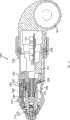
参见图31,用于CMM10的一种可替代的测量探针如标记232所示。测量探针232与图29中的测量探针28相似,其中的主要区别在于探针232包括一旋转手柄罩234。该旋转手柄罩234安装在一对间隔开的轴承236、238上,该轴承又安装在一内芯或支承件240上,从而该旋转罩234可以自由地绕着内芯240旋转。Referring to FIG. 31 , an alternative measurement probe for use with the
轴承236、238优选为径向轴承并且使得由于探针手柄产生的在该铰接臂上的附加力矩最小化。值得注意的是,该开关电路板208’以及相应的开关200’、202’和LED204’都安装在该旋转手柄罩234上以便与其一起旋转。在旋转期间,采用一种普通的滑环机构242为处理电路板118’提供电连接,该滑环机构包括一些现有的间隔开的弹簧爪式定位装置(spring finger)242,该弹簧爪与固定环形凹槽244接触。这些接触凹槽244采用滑环导体242又与电路板118’进行电连接。该旋转手柄罩234以及开关组件因此采用滑环导体242与内芯或探针轴240电连接。该探针手柄罩234的旋转使得开关200’、202’能够定向成方便于使用者。这使得该铰接臂14’可以在操作过程中通过使得无事实证明的力(undocumented force)最小化而进行精确的测量。该旋转手柄罩优选由一刚性聚合物制成并且其上设有一些适当的凹部246和248,以便方便该探针的操作者容易握持和操控。
可以理解的是,探针232的剩余部分与探针28十分相似,包括在盖体220中设置一永久而一体安装的接触探针210。需要指出的是,开关200’、202’都具有不同的高度和表面纹路以便方便辨识。It will be appreciated that the remainder of the
在CMM领域,旋转手柄罩234的一个显著的优点在于他可以弱化象在前述美国专利US5611147中所披露的对第七旋转轴的需要。可以理解到的是,增加第七轴会使得CMM更为复杂和昂贵并且增加了系统导致误差的可能。使用可旋转的探针232弱化了对一种“真正的”第七轴的需要,因为在没有第七转换器和相应的轴承、编码器以及电子器件的复杂情况下它使得探针能够提供在探针末端的手柄位置所需的旋转。A significant advantage of the
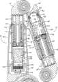
在需要使用具有“真正”第七轴的测量探针的情况下,也就是说,在测量探针具有用于测量旋转运动的第七旋转编码器的情况下,图37-40表示出了这种中测量探针。参见这些图,所示的测量探针500具有这样的测量探针,该探针基本上与图29中的测量探针相似,其主要区别在于插入了一如上所述类型的模制轴承/转换器机芯502,执行和确认开关540、506位于该测量探针的侧面并且包括一可拆除的手柄508。In cases where it is desired to use a measurement probe with a "true" seventh axis, that is, where the measurement probe has a seventh rotary encoder for measuring rotational motion, Figures 37-40 illustrate this. Kind of measuring probe. Referring to these figures, the
可以理解到的是,该模制轴承/转换器机芯502基本上与上面详细描述的机芯相似并且包括:一可旋转的轴,一对位于该轴上的轴承,一光学编码器盘,至少一个(优选为两个)光学读出磁头彼此间隔开的并且与该编码器盘光学连通的以及一包围该轴承、光学编码器盘、读出磁头以及至少一部分轴的壳体,以便构成该分散(discrete)的模制轴承/转换器机芯。编码器电子器件的电路板503位于探针500的开口504中。成对的执行和确认按钮504、506布置在探针500的向下凸出的壳体部分510的任意一侧,其中这些按钮与适当的PC板512连接,就和图29中的实施例中的测量探针一样。同样,和在前面所述的实施例一样,指示灯513位于按钮504、506之间。在壳体510中的一对螺纹孔514接收紧固件以便可拆除地安装手柄508,该手柄用于在测量探针使用过程中方便进行旋转操控。It will be appreciated that the molded bearing/
在所有其它实质方面,测量探针500都与图29中的测量探针28相似,包括优选使用永久安装的接触触发器探针516以及可拆除的盖体,该盖体与一固定探针518相配合同时保护该接触触发器探针。需要理解的是,包含在测量探针500内的第七旋转编码器502使得CMM10能很容易地与现有的激光行扫描仪和其他外围设备连接起来使用。In all other substantial respects,
参见图2-4以及25,根据本发明的一个重要特征,便携式电源用来为CMM10供电,因此提供一种完全便携式的CMM。与现有CMM进行对比不同在于该电源仅仅基于一种AC电缆。此外,CMM10还可以经普通插座通过AC/DC适配器直接由AC电缆供电。如图2、3以及25所示,标记22所示的为一种普通充电电池(例如锂离子电磁)。电池22采用机械方式电连接在普通电池支承件252中,该电池支承件252又与普通电源以及位于电路板20中的电池充电电路部件254进行电连接。一开/关258(见图3)以及快速连通接口(优选为USB接口)也与电路板20连通。该铰接臂14的关节的电子器件采用RS-485总线与电路板20相连。电池22可以在一独立的充电器上进行充电,或者就象在普通的录像机上所见到的那样在支承件252上就地充电。可以理解的的是,该便携式计算机172(见图2)可以依靠其内置电池工作几个小时和/或或者可以电连接到CMM10的电源单元上。Referring to Figures 2-4 and 25, according to an important feature of the present invention, a portable power source is used to power the
根据本发明的该在板电源/充电器单元优选作设置成为CMM10的一个一体化部分,例如通过将该部件作为基座12的一个一体化部分以及更具体来说作为该塑料基座壳体26A、26B的一部分。需要指出的是,基座壳体26A、26B包括一个较小的储存区域259,该区域具有一可枢轴转动的盖子262,以便存储备用电池、探针等。The on-board power supply/charger unit according to the invention is preferably provided as an integral part of the
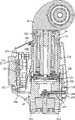
下面参考图4、25以及32-34对用于CMM10的新颖磁性安装装置进行描述。该磁性安装装置在图4、25、32以及33中采用标记24来进行总体表示。该磁性固定件24包括一圆柱形非磁性壳体266,该壳体的上端的末端形成螺纹部分268。和在CMM10中所使用的所有优选的螺纹一样,螺纹268是一锥形螺纹,该锥形螺纹用来与第一长关节16上的螺纹126进行螺纹连接,如图25所示。非磁性壳体266有一基本上圆柱形结构,不同之处在于两个纵向延伸部分270、272,这两个延伸部分彼此相对成180°并且从壳体266向外和向下延伸。一对半圆柱形壳体274、276安装在纵向延伸部分270、272的任意一侧上,其中每一个都由一种“磁性”材料构成,也就是说,采用一种能够被磁化的材料构成,例如铁或磁性不锈钢。“磁性”壳体的两半274、276以及纵向延伸部分270、272一起形成一端部开口的圆柱形封闭件,以便接受和容纳一磁芯278。该磁芯278为一椭圆形,其中一非磁性中心部件280夹在一对稀土金属磁体(例如钕铁硼)282、284之间。一轴向孔286穿过该非磁性的中心部件280。一圆形盖板288位于磁芯278的下面并且位于由壳体部件274、276已经纵向延伸部分270、272形成的下部壳体内。一轴290穿过壳体266中的圆形孔292并向下延伸穿过磁芯278的轴向孔286。轴290由一上部轴承292以及一下部轴承294支承以便旋转。上部轴承292安装在壳体266内的一内圆柱形凹部中而下部轴承294安装在盖板288中的相似圆柱形凹部内。一控制杆垂直于轴290向外延伸,并且和之后将要描述的那样提供了一个用于该磁性固定件264的开/关机构。控制杆296经一穿过壳体266的槽297延伸到壳体266之外(见图25)。A novel magnetic mounting arrangement for the
控制杆296、轴290以及轴承292、294构成的组件采用上部螺纹紧固件298以及一下部固定环300固定在一起。可以理解的是,磁性固定件264的各种部件还通过例如螺纹紧固件302和304进行固定,螺纹紧固件302将壳体266连接到“磁性”材料壳体部分274、276上,而螺纹紧固件304将壳体部分274、276与盖板288相互连接起来。此外,螺纹紧固件306将壳体266的纵向延伸部分270、272固定到盖板288上。销子308安装在磁芯278中一横向孔以及轴290中的一横向孔中从而将轴290锁定到磁芯278上。这样,当控制杆296旋转时,轴290将会借助于轴连接件208而使磁芯278旋转。The assembly of
如图1、3以及25所示,控制杆296与手柄310相连,该手柄位于基座12的外部而很容易接近并且用来驱动磁性固定件264。为了实现这种驱动,只需要使得手柄310移动(在图1中而从右向左)。手柄310的运动又使得控制杆296旋转,而控制杆296的转动又使得轴290旋转,随后轴290的旋转使得稀土金属磁体282、284从其非操作位置(在该位置,磁体282、284与非磁性延伸部分270、272对齐)转动到一驱动位置,在该驱动位置,磁体282、284与磁性材料274、276对齐。当该磁体如上所述与该磁性材料对齐时,就形成一磁场(磁通量)。同样,当磁体282、284与该磁性材料274、276不对齐时,该磁通路径被中断。As shown in FIGS. 1 , 3 and 25 , the
在该状态下,磁性基座与其所坐在的桌面分离。不过,需要注意的是,在非对齐状态下,将会存在一些剩余磁通。在“关闭”状态下的这些较小的剩余磁通是本发明的一正面特征,因为在磁性基座从桌面上被替换时少量的磁通反作用于磁体并使得控制杆296自动地旋转返回到“开启”状态。需要理解的是,当磁体与磁性材料对齐时,将会形成一强磁场并且半圆形部件274、276将会磁性地连接在形成于其底部处的环形表面上,如图25和33中的标记312处所示。In this state, the magnetic base is separated from the tabletop it sits on. However, it should be noted that in the non-aligned state, there will be some residual flux. These small residual fluxes in the "off" state are a positive feature of the present invention because a small amount of flux reacts against the magnet and causes the
本发明的磁性固定件264提供了一种完全集成在一起而又可以拆卸安装的装置,因为其(通过螺纹268)可拆卸地安装在一起并且可以由其他连接件例如螺钉固定件或真空固定件来替代。淡然,为了适当地使用,磁性固定件264必须布置在一可磁化的表面上并且(通过控制杆296)受到驱动而进行工作。在需要安装到非磁性表面(例如花岗岩)上的情况下,就必须在该磁芯基座和非磁性表面之间使用转换面板和其它适当的机构。The magnetic mount 264 of the present invention provides a fully integrated yet removably mountable device as it is removably mounted together (via threads 268) and can be secured by other attachments such as screw mounts or vacuum mounts. to replace. Of course, for proper use, the magnetic mount 264 must be disposed on a magnetizable surface and actuated (via the lever 296) to operate. Where mounting to a non-magnetic surface such as granite is desired, a transition panel and other suitable mechanism must be used between the core base and the non-magnetic surface.
尽管所示的和所描述的是优选实施例,但是在不脱离本发明和精神和范围的情况下依然进行各种改变和替换。因此,需要理解的是本发明仅仅是进行了一些阐述性的说明而不是进行限制性说明。While shown and described are preferred embodiments, various changes and substitutions can be made without departing from the spirit and scope of the invention. Accordingly, it is to be understood that the present invention has been described by way of illustration only and not limitation.
Claims (44)
Translated fromChineseApplications Claiming Priority (4)
| Application Number | Priority Date | Filing Date | Title |
|---|---|---|---|
| US35759902P | 2002-02-14 | 2002-02-14 | |
| US60/357,599 | 2002-02-14 | ||
| US39490802P | 2002-07-10 | 2002-07-10 | |
| US60/394,908 | 2002-07-10 |
Publications (2)
| Publication Number | Publication Date |
|---|---|
| CN1630804A CN1630804A (en) | 2005-06-22 |
| CN100473940Ctrue CN100473940C (en) | 2009-04-01 |
Family
ID=27737606
Family Applications (3)
| Application Number | Title | Priority Date | Filing Date |
|---|---|---|---|
| CNB038036851AExpired - Fee RelatedCN100523709C (en) | 2002-02-14 | 2003-02-13 | Portable coordinate measurement machine with articulated jib |
| CNB038036746AExpired - Fee RelatedCN100473942C (en) | 2002-02-14 | 2003-02-13 | Portable Coordinate Measuring Machine with Integrated Line Laser Scanner |
| CNB038036789AExpired - Fee RelatedCN100473940C (en) | 2002-02-14 | 2003-02-13 | Portable coordinate measurement machine with articulated jib |
Family Applications Before (2)
| Application Number | Title | Priority Date | Filing Date |
|---|---|---|---|
| CNB038036851AExpired - Fee RelatedCN100523709C (en) | 2002-02-14 | 2003-02-13 | Portable coordinate measurement machine with articulated jib |
| CNB038036746AExpired - Fee RelatedCN100473942C (en) | 2002-02-14 | 2003-02-13 | Portable Coordinate Measuring Machine with Integrated Line Laser Scanner |
Country Status (8)
| Country | Link |
|---|---|
| US (13) | US6935036B2 (en) |
| EP (3) | EP1474653B1 (en) |
| JP (3) | JP2005517909A (en) |
| CN (3) | CN100523709C (en) |
| AT (2) | ATE382845T1 (en) |
| AU (3) | AU2003223173A1 (en) |
| DE (2) | DE60314598T2 (en) |
| WO (3) | WO2003069267A1 (en) |
Cited By (1)
| Publication number | Priority date | Publication date | Assignee | Title |
|---|---|---|---|---|
| CN108627136A (en)* | 2017-03-16 | 2018-10-09 | 株式会社三丰 | Shape measuring apparatus |
Families Citing this family (253)
| Publication number | Priority date | Publication date | Assignee | Title |
|---|---|---|---|---|
| GB9515311D0 (en) | 1995-07-26 | 1995-09-20 | 3D Scanners Ltd | Stripe scanners and methods of scanning |
| US6952882B2 (en) | 2002-02-14 | 2005-10-11 | Faro Technologies, Inc. | Portable coordinate measurement machine |
| US7246030B2 (en) | 2002-02-14 | 2007-07-17 | Faro Technologies, Inc. | Portable coordinate measurement machine with integrated line laser scanner |
| US7519493B2 (en) | 2002-02-14 | 2009-04-14 | Faro Technologies, Inc. | Portable coordinate measurement machine with integrated line laser scanner |
| US7073271B2 (en)* | 2002-02-14 | 2006-07-11 | Faro Technologies Inc. | Portable coordinate measurement machine |
| US7881896B2 (en) | 2002-02-14 | 2011-02-01 | Faro Technologies, Inc. | Portable coordinate measurement machine with integrated line laser scanner |
| AU2003223173A1 (en) | 2002-02-14 | 2003-09-04 | Faro Technologies, Inc. | Portable coordinate measurement machine with integrated line laser scanner |
| US6973734B2 (en) | 2002-02-14 | 2005-12-13 | Faro Technologies, Inc. | Method for providing sensory feedback to the operator of a portable measurement machine |
| US6957496B2 (en) | 2002-02-14 | 2005-10-25 | Faro Technologies, Inc. | Method for improving measurement accuracy of a portable coordinate measurement machine |
| USRE42082E1 (en) | 2002-02-14 | 2011-02-01 | Faro Technologies, Inc. | Method and apparatus for improving measurement accuracy of a portable coordinate measurement machine |
| DE60306902T2 (en)* | 2002-02-26 | 2007-01-11 | Faro Technologies, Inc., Lake Mary | STANDARD VACUUM ADAPTER |
| AU2003282242A1 (en)* | 2002-11-15 | 2004-06-15 | Alan George Rock | Level, angle and distance measuring device |
| JP4707306B2 (en)* | 2003-02-28 | 2011-06-22 | 株式会社小坂研究所 | Articulated coordinate measuring device |
| US7257248B2 (en)* | 2003-03-27 | 2007-08-14 | General Electric Company | Non-contact measurement system and method |
| CA2522097C (en) | 2003-04-28 | 2012-09-25 | Stephen James Crampton | Cmm arm with exoskeleton |
| US7672810B2 (en)* | 2003-10-15 | 2010-03-02 | 3D Scanners Ltd. | Method, device and computer program for evaluating an object using a virtual representation of said object |
| FR2861843B1 (en) | 2003-10-29 | 2006-07-07 | Romain Granger | CONNECTING DEVICE ASSOCIATED WITH A THREE DIMENSIONAL MEASURING APPARATUS ARM WITH ARTICULATED ARMS |
| JP4481137B2 (en)* | 2003-11-13 | 2010-06-16 | アスモ株式会社 | Motor, rotation control device, and rotation detection circuit |
| US7152456B2 (en) | 2004-01-14 | 2006-12-26 | Romer Incorporated | Automated robotic measuring system |
| US7693325B2 (en) | 2004-01-14 | 2010-04-06 | Hexagon Metrology, Inc. | Transprojection of geometry data |
| US7508971B2 (en)* | 2004-05-28 | 2009-03-24 | The Boeing Company | Inspection system using coordinate measurement machine and associated method |
| US7253908B2 (en)* | 2004-07-22 | 2007-08-07 | The Boeing Company | Non-destructive inspection using laser profiling and associated method |
| US7165453B2 (en)* | 2004-07-23 | 2007-01-23 | Electric Power Research Institute | Flexible electromagnetic acoustic transducer sensor |
| KR100865056B1 (en)* | 2004-07-26 | 2008-10-23 | 일렉트릭 파워 리서치 인스티튜트, 인크. | Measurement device |
| GB0424729D0 (en)* | 2004-11-09 | 2004-12-08 | Crampton Stephen | Probe end module for articulated arms |
| US7222543B2 (en)* | 2004-11-23 | 2007-05-29 | Dr. Johannes Heidenhain Gmbh | Modular encoder, method of producing a modular encoder, and system for measuring angular movement |
| US7167252B2 (en)* | 2004-11-23 | 2007-01-23 | Kevin Gallup | Method and apparatus for creating cavities in packaging materials for artifacts, art objects and fragile or other valuable items |
| WO2006093899A2 (en) | 2005-02-28 | 2006-09-08 | Electric Power Research Institute, Inc. | Method for inspection and repair |
| US7333219B2 (en)* | 2005-03-29 | 2008-02-19 | Mitutoyo Corporation | Handheld metrology imaging system and method |
| FR2884910B1 (en)* | 2005-04-20 | 2007-07-13 | Romer Sa | THREE-DIMENSIONAL MEASURING APPARATUS WITH ARTICULATED ARMS COMPRISING A PLURALITY OF JOINT AXES |
| EP2202482A1 (en)* | 2005-06-23 | 2010-06-30 | Faro Technologies, Inc. | Apparatus and method for relocating an articulating-arm coordinate measuring machine |
| WO2007017235A2 (en)* | 2005-08-08 | 2007-02-15 | 3D Scanners Ltd | Cmm arm with enhanced manual control |
| GB0516276D0 (en)* | 2005-08-08 | 2005-09-14 | Crampton Stephen | Robust cmm arm with exoskeleton |
| WO2007033273A2 (en)* | 2005-09-13 | 2007-03-22 | Romer Incorporated | Vehicle comprising an articulator of a coordinate measuring machine |
| FR2892034A1 (en)* | 2005-10-14 | 2007-04-20 | Soudure Autogene Francaise Sa | ARC WELDING STATION WITH DATA MASS STORAGE MEMORY |
| US8142528B2 (en)* | 2005-11-30 | 2012-03-27 | General Electric Company | Methods and systems of reducing viscosity of gasification system slag |
| DE202006005643U1 (en)* | 2006-03-31 | 2006-07-06 | Faro Technologies Inc., Lake Mary | Device for three-dimensional detection of a spatial area |
| US7568293B2 (en)* | 2006-05-01 | 2009-08-04 | Paul Ferrari | Sealed battery for coordinate measurement machine |
| US7805854B2 (en) | 2006-05-15 | 2010-10-05 | Hexagon Metrology, Inc. | Systems and methods for positioning and measuring objects using a CMM |
| DE102006031580A1 (en) | 2006-07-03 | 2008-01-17 | Faro Technologies, Inc., Lake Mary | Method and device for the three-dimensional detection of a spatial area |
| CN101529211B (en)* | 2006-08-21 | 2011-12-21 | Gsi集团公司 | Rotary Optical Encoder Using Multiple Sub-Encoders With Common Grazed Substrate |
| US8006399B2 (en)* | 2006-09-05 | 2011-08-30 | Renishaw Plc | Surface sensing device |
| GB0617344D0 (en)* | 2006-09-05 | 2006-10-11 | Renishaw Plc | Surface sensing device |
| US7439713B2 (en)* | 2006-09-20 | 2008-10-21 | Pratt & Whitney Canada Corp. | Modulation control of power generation system |
| EP2092269B1 (en)* | 2006-11-20 | 2019-05-01 | Hexagon Technology Center GmbH | Coordinate measurement machine with improved joint |
| US7784194B2 (en)* | 2006-11-30 | 2010-08-31 | Faro Technologies, Inc. | Portable coordinate measurement machine |
| WO2008080142A1 (en)* | 2006-12-22 | 2008-07-03 | Romer, Inc. | Improved joint axis for coordinate measurement machine |
| US20080189072A1 (en)* | 2007-02-01 | 2008-08-07 | Nescom Inc. | High resolution encoder within a swivel |
| WO2008121073A1 (en)* | 2007-04-03 | 2008-10-09 | Hexagon Metrology Ab | Method and device for exact measurement of objects |
| US9545009B2 (en) | 2007-05-23 | 2017-01-10 | Spectra Logic, Corporation | Passive alterable electrical component |
| WO2008154408A1 (en)* | 2007-06-06 | 2008-12-18 | Tobey Wayland E | Modular hybrid snake arm |
| US7546689B2 (en)* | 2007-07-09 | 2009-06-16 | Hexagon Metrology Ab | Joint for coordinate measurement device |
| DE102007032538B4 (en)* | 2007-07-12 | 2015-03-26 | Siemens Aktiengesellschaft | Medical diagnostic and / or intervention device |
| US8457790B2 (en)* | 2007-09-14 | 2013-06-04 | Zimmer, Inc. | Robotic calibration method |
| EP2037214A1 (en) | 2007-09-14 | 2009-03-18 | Leica Geosystems AG | Method and measuring device for measuring surfaces |
| US7774949B2 (en)* | 2007-09-28 | 2010-08-17 | Hexagon Metrology Ab | Coordinate measurement machine |
| US7797849B2 (en)* | 2007-10-31 | 2010-09-21 | Immersion Corporation | Portable metrology device |
| JP2009122066A (en)* | 2007-11-19 | 2009-06-04 | Mitsutoyo Corp | Non-contact three-dimensional measurement method and device thereof |
| EP2068124A1 (en) | 2007-12-04 | 2009-06-10 | Metris IPR N.V. | Articulated arm measuring machine endowed with multiple measurement disks |
| US8122610B2 (en)* | 2008-03-28 | 2012-02-28 | Hexagon Metrology, Inc. | Systems and methods for improved coordination acquisition member comprising calibration information |
| US7779548B2 (en)* | 2008-03-28 | 2010-08-24 | Hexagon Metrology, Inc. | Coordinate measuring machine with rotatable grip |
| EP2108917B1 (en) | 2008-04-07 | 2012-10-03 | Leica Geosystems AG | Articulated arm coordinate measuring machine |
| USD599226S1 (en) | 2008-04-11 | 2009-09-01 | Hexagon Metrology, Inc. | Portable coordinate measurement machine |
| US7640674B2 (en)* | 2008-05-05 | 2010-01-05 | Hexagon Metrology, Inc. | Systems and methods for calibrating a portable coordinate measurement machine |
| US8035823B2 (en)* | 2008-09-05 | 2011-10-11 | 3Dm Devices Inc. | Hand-held surface profiler |
| US7908757B2 (en) | 2008-10-16 | 2011-03-22 | Hexagon Metrology, Inc. | Articulating measuring arm with laser scanner |
| US9482755B2 (en) | 2008-11-17 | 2016-11-01 | Faro Technologies, Inc. | Measurement system having air temperature compensation between a target and a laser tracker |
| EP2194357A1 (en) | 2008-12-03 | 2010-06-09 | Leica Geosystems AG | Optical sensor element for a measuring device and coupling element for this containing measuring device unit |
| US8176809B2 (en)* | 2008-12-10 | 2012-05-15 | GM Global Technology Operations LLC | Planar torsion spring |
| DE102008062624A1 (en)* | 2008-12-17 | 2010-06-24 | Kuka Roboter Gmbh | Hand-held device and method for detecting the spatial position of an operating point of a manipulator |
| US7983790B2 (en)* | 2008-12-19 | 2011-07-19 | The Boeing Company | Component repair using reverse engineering |
| DE102009010465B3 (en)* | 2009-02-13 | 2010-05-27 | Faro Technologies, Inc., Lake Mary | laser scanner |
| DE102009015920B4 (en) | 2009-03-25 | 2014-11-20 | Faro Technologies, Inc. | Device for optically scanning and measuring an environment |
| US9551575B2 (en) | 2009-03-25 | 2017-01-24 | Faro Technologies, Inc. | Laser scanner having a multi-color light source and real-time color receiver |
| US8082673B2 (en) | 2009-11-06 | 2011-12-27 | Hexagon Metrology Ab | Systems and methods for control and calibration of a CMM |
| WO2010116203A1 (en)* | 2009-04-06 | 2010-10-14 | Aktiebolaget Skf | Detection system, joint system provided with such a detection system and automotive vehicle equipped with such a joint system |
| DE102009017581B4 (en)* | 2009-04-18 | 2021-06-24 | Igus Gmbh | Multi-axis joint especially for robotics |
| US8423190B1 (en)* | 2009-06-11 | 2013-04-16 | Kabushiki Kaisha Yaskawa Denki | Manipulator system |
| US8104189B2 (en)* | 2009-06-30 | 2012-01-31 | Hexagon Metrology Ab | Coordinate measurement machine with vibration detection |
| DE102009031712A1 (en) | 2009-07-04 | 2011-08-04 | Schaeffler Technologies GmbH & Co. KG, 91074 | Bearing cartridge, in particular for the articulated arm of a three-dimensional coordinate measuring device |
| DE102009035336B3 (en) | 2009-07-22 | 2010-11-18 | Faro Technologies, Inc., Lake Mary | Device for optical scanning and measuring of environment, has optical measuring device for collection of ways as ensemble between different centers returning from laser scanner |
| DE102009035337A1 (en) | 2009-07-22 | 2011-01-27 | Faro Technologies, Inc., Lake Mary | Method for optically scanning and measuring an object |
| US20110285981A1 (en)* | 2010-05-18 | 2011-11-24 | Irvine Sensors Corporation | Sensor Element and System Comprising Wide Field-of-View 3-D Imaging LIDAR |
| ES2511869T3 (en)* | 2009-10-22 | 2014-10-23 | Abb Research Ltd. | Robot part and method to protect a robot part |
| US9529083B2 (en) | 2009-11-20 | 2016-12-27 | Faro Technologies, Inc. | Three-dimensional scanner with enhanced spectroscopic energy detector |
| DE102009057101A1 (en) | 2009-11-20 | 2011-05-26 | Faro Technologies, Inc., Lake Mary | Device for optically scanning and measuring an environment |
| US9113023B2 (en) | 2009-11-20 | 2015-08-18 | Faro Technologies, Inc. | Three-dimensional scanner with spectroscopic energy detector |
| DE102009055988B3 (en) | 2009-11-20 | 2011-03-17 | Faro Technologies, Inc., Lake Mary | Device, particularly laser scanner, for optical scanning and measuring surrounding area, has light transmitter that transmits transmission light ray by rotor mirror |
| US9210288B2 (en) | 2009-11-20 | 2015-12-08 | Faro Technologies, Inc. | Three-dimensional scanner with dichroic beam splitters to capture a variety of signals |
| DE102009055989B4 (en) | 2009-11-20 | 2017-02-16 | Faro Technologies, Inc. | Device for optically scanning and measuring an environment |
| US20110213247A1 (en)* | 2010-01-08 | 2011-09-01 | Hexagon Metrology, Inc. | Articulated arm with imaging device |
| US8630314B2 (en) | 2010-01-11 | 2014-01-14 | Faro Technologies, Inc. | Method and apparatus for synchronizing measurements taken by multiple metrology devices |
| WO2011090895A1 (en)* | 2010-01-20 | 2011-07-28 | Faro Technologies, Inc. | Portable articulated arm coordinate measuring machine with multi-bus arm technology |
| US8898919B2 (en) | 2010-01-20 | 2014-12-02 | Faro Technologies, Inc. | Coordinate measurement machine with distance meter used to establish frame of reference |
| US8677643B2 (en) | 2010-01-20 | 2014-03-25 | Faro Technologies, Inc. | Coordinate measurement machines with removable accessories |
| US8284407B2 (en) | 2010-01-20 | 2012-10-09 | Faro Technologies, Inc. | Coordinate measuring machine having an illuminated probe end and method of operation |
| US9628775B2 (en) | 2010-01-20 | 2017-04-18 | Faro Technologies, Inc. | Articulated arm coordinate measurement machine having a 2D camera and method of obtaining 3D representations |
| US8942940B2 (en)* | 2010-01-20 | 2015-01-27 | Faro Technologies, Inc. | Portable articulated arm coordinate measuring machine and integrated electronic data processing system |
| US8615893B2 (en) | 2010-01-20 | 2013-12-31 | Faro Technologies, Inc. | Portable articulated arm coordinate measuring machine having integrated software controls |
| US9607239B2 (en) | 2010-01-20 | 2017-03-28 | Faro Technologies, Inc. | Articulated arm coordinate measurement machine having a 2D camera and method of obtaining 3D representations |
| US9163922B2 (en) | 2010-01-20 | 2015-10-20 | Faro Technologies, Inc. | Coordinate measurement machine with distance meter and camera to determine dimensions within camera images |
| US9879976B2 (en) | 2010-01-20 | 2018-01-30 | Faro Technologies, Inc. | Articulated arm coordinate measurement machine that uses a 2D camera to determine 3D coordinates of smoothly continuous edge features |
| US8875409B2 (en) | 2010-01-20 | 2014-11-04 | Faro Technologies, Inc. | Coordinate measurement machines with removable accessories |
| US8832954B2 (en) | 2010-01-20 | 2014-09-16 | Faro Technologies, Inc. | Coordinate measurement machines with removable accessories |
| EP2372302A1 (en) | 2010-03-26 | 2011-10-05 | Leica Geosystems AG | Measuring method for a surface measuring machine |
| USD643319S1 (en) | 2010-03-29 | 2011-08-16 | Hexagon Metrology Ab | Portable coordinate measurement machine |
| DE102010013923A1 (en)* | 2010-04-01 | 2011-10-06 | Wittenstein Ag | Manipulator, particularly robotic palletizer, hinged bracket robot or linear actuator for machine tool, has moving manipulator element, and drive disposed on moving element of manipulator |
| US9772394B2 (en) | 2010-04-21 | 2017-09-26 | Faro Technologies, Inc. | Method and apparatus for following an operator and locking onto a retroreflector with a laser tracker |
| US8537371B2 (en) | 2010-04-21 | 2013-09-17 | Faro Technologies, Inc. | Method and apparatus for using gestures to control a laser tracker |
| US8422034B2 (en) | 2010-04-21 | 2013-04-16 | Faro Technologies, Inc. | Method and apparatus for using gestures to control a laser tracker |
| US8619265B2 (en) | 2011-03-14 | 2013-12-31 | Faro Technologies, Inc. | Automatic measurement of dimensional data with a laser tracker |
| US9377885B2 (en) | 2010-04-21 | 2016-06-28 | Faro Technologies, Inc. | Method and apparatus for locking onto a retroreflector with a laser tracker |
| US9400170B2 (en) | 2010-04-21 | 2016-07-26 | Faro Technologies, Inc. | Automatic measurement of dimensional data within an acceptance region by a laser tracker |
| US8724119B2 (en) | 2010-04-21 | 2014-05-13 | Faro Technologies, Inc. | Method for using a handheld appliance to select, lock onto, and track a retroreflector with a laser tracker |
| US9335160B2 (en) | 2010-04-26 | 2016-05-10 | Nikon Corporation | Profile measuring apparatus |
| DE102010020925B4 (en) | 2010-05-10 | 2014-02-27 | Faro Technologies, Inc. | Method for optically scanning and measuring an environment |
| DE102010017304A1 (en) | 2010-06-09 | 2011-12-15 | Martin Knauer | Coordinate measuring apparatus, method for operating a coordinate measuring apparatus and computer program product |
| US9368046B2 (en) | 2010-07-14 | 2016-06-14 | Macronix International Co., Ltd. | Color tactile vision system |
| DE102010032725B4 (en)* | 2010-07-26 | 2012-04-26 | Faro Technologies, Inc. | Device for optically scanning and measuring an environment |
| DE102010032726B3 (en) | 2010-07-26 | 2011-11-24 | Faro Technologies, Inc. | Device for optically scanning and measuring an environment |
| DE102010032723B3 (en) | 2010-07-26 | 2011-11-24 | Faro Technologies, Inc. | Device for optically scanning and measuring an environment |
| DE102010033561B3 (en) | 2010-07-29 | 2011-12-15 | Faro Technologies, Inc. | Device for optically scanning and measuring an environment |
| US8127458B1 (en)* | 2010-08-31 | 2012-03-06 | Hexagon Metrology, Inc. | Mounting apparatus for articulated arm laser scanner |
| GB2501390B (en) | 2010-09-08 | 2014-08-06 | Faro Tech Inc | A laser scanner or laser tracker having a projector |
| USD676309S1 (en)* | 2010-11-16 | 2013-02-19 | Faro Technologies, Inc. | Base for a device |
| USD662427S1 (en) | 2010-11-16 | 2012-06-26 | Faro Technologies, Inc. | Measurement device |
| US9168654B2 (en) | 2010-11-16 | 2015-10-27 | Faro Technologies, Inc. | Coordinate measuring machines with dual layer arm |
| JP5771286B2 (en) | 2011-01-14 | 2015-08-26 | ファロ テクノロジーズ インコーポレーテッド | Case for equipment |
| GB2503390B (en) | 2011-03-03 | 2014-10-29 | Faro Tech Inc | Target apparatus and method |
| EP2511656A1 (en) | 2011-04-14 | 2012-10-17 | Hexagon Technology Center GmbH | Measuring system for determining the 3D coordinates of an object surface |
| JP2014516409A (en) | 2011-04-15 | 2014-07-10 | ファロ テクノロジーズ インコーポレーテッド | Improved position detector for laser trackers. |
| US9686532B2 (en) | 2011-04-15 | 2017-06-20 | Faro Technologies, Inc. | System and method of acquiring three-dimensional coordinates using multiple coordinate measurement devices |
| US9164173B2 (en) | 2011-04-15 | 2015-10-20 | Faro Technologies, Inc. | Laser tracker that uses a fiber-optic coupler and an achromatic launch to align and collimate two wavelengths of light |
| US9482529B2 (en) | 2011-04-15 | 2016-11-01 | Faro Technologies, Inc. | Three-dimensional coordinate scanner and method of operation |
| CN103782130B (en)* | 2011-07-08 | 2017-06-20 | 卡尔蔡司工业测量技术有限公司 | Error correction and/or avoidance when measuring the coordinates of a workpiece |
| JP2014524570A (en) | 2011-08-12 | 2014-09-22 | ウオーターズ・テクノロジーズ・コーポレイシヨン | Rotating rheometer with dual read head optical encoder |
| DE102011113611B3 (en)* | 2011-09-16 | 2012-10-04 | PTW-Freiburg Physikalisch-Technische Werkstätten Dr. Pychlau GmbH | Measuring system for use in water phantom in context of quality assurance or commissioning of accelerator, has conversion unit passing commands to control unit, so that movement of support takes place and system comprises RZ-axis |
| CN102445172A (en)* | 2011-10-23 | 2012-05-09 | 江苏阳明船舶装备制造技术有限公司 | Method for measuring position relation of space object |
| CN102410933B (en)* | 2011-11-24 | 2015-06-10 | 河北省电力建设调整试验所 | Bank side measuring rocker arm base |
| CN102519361B (en)* | 2011-12-28 | 2014-03-05 | 二重集团(德阳)重型装备股份有限公司 | Special worktable for laser tracker and laser tracking measurement method |
| US8763267B2 (en) | 2012-01-20 | 2014-07-01 | Hexagon Technology Center Gmbh | Locking counterbalance for a CMM |
| DE102012100609A1 (en) | 2012-01-25 | 2013-07-25 | Faro Technologies, Inc. | Device for optically scanning and measuring an environment |
| WO2013112455A1 (en) | 2012-01-27 | 2013-08-01 | Faro Technologies, Inc. | Inspection method with barcode identification |
| CN102632508B (en)* | 2012-04-17 | 2015-04-29 | 浙江大学 | Planar torsion spring suitable for robot joints |
| CN103455045A (en)* | 2012-05-30 | 2013-12-18 | 鸿富锦精密工业(深圳)有限公司 | Touch movement control system and touch movement control method |
| US9069355B2 (en) | 2012-06-08 | 2015-06-30 | Hexagon Technology Center Gmbh | System and method for a wireless feature pack |
| DE112013002892T5 (en)* | 2012-06-11 | 2015-02-26 | Faro Technologies, Inc. | Coordinate measuring machines with removable accessories |
| EP2677270B1 (en) | 2012-06-22 | 2015-01-28 | Hexagon Technology Center GmbH | Articulated Arm CMM |
| WO2014006147A1 (en) | 2012-07-04 | 2014-01-09 | Hexagon Technology Center Gmbh | Optical position transmitter with analog memory unit |
| US8997362B2 (en) | 2012-07-17 | 2015-04-07 | Faro Technologies, Inc. | Portable articulated arm coordinate measuring machine with optical communications bus |
| EP2690395A1 (en) | 2012-07-24 | 2014-01-29 | Hexagon Technology Center GmbH | Interferometric distance measuring assembly and method |
| EP2690396A1 (en) | 2012-07-24 | 2014-01-29 | Hexagon Technology Center GmbH | Interferometric distance measuring assembly and method |
| DE102012107544B3 (en) | 2012-08-17 | 2013-05-23 | Faro Technologies, Inc. | Optical scanning device i.e. laser scanner, for evaluating environment, has planetary gears driven by motor over vertical motor shaft and rotating measuring head relative to foot, where motor shaft is arranged coaxial to vertical axle |
| EP2698599A1 (en) | 2012-08-17 | 2014-02-19 | Hexagon Technology Center GmbH | Coordinate measuring method and coordinate measurement machine for measuring surfaces with an optical sensor |
| US10067231B2 (en) | 2012-10-05 | 2018-09-04 | Faro Technologies, Inc. | Registration calculation of three-dimensional scanner data performed between scans based on measurements by two-dimensional scanner |
| US9513107B2 (en) | 2012-10-05 | 2016-12-06 | Faro Technologies, Inc. | Registration calculation between three-dimensional (3D) scans based on two-dimensional (2D) scan data from a 3D scanner |
| DE102012109481A1 (en) | 2012-10-05 | 2014-04-10 | Faro Technologies, Inc. | Device for optically scanning and measuring an environment |
| EP2762832B1 (en) | 2013-01-30 | 2018-06-13 | Hexagon Technology Center GmbH | Optical single-point measurement |
| US9250214B2 (en) | 2013-03-12 | 2016-02-02 | Hexagon Metrology, Inc. | CMM with flaw detection system |
| US9041914B2 (en) | 2013-03-15 | 2015-05-26 | Faro Technologies, Inc. | Three-dimensional coordinate scanner and method of operation |
| WO2015031602A1 (en)* | 2013-08-29 | 2015-03-05 | Rhk Technology, Inc. | Optical alignment interface |
| CN103644861B (en)* | 2013-12-09 | 2016-04-06 | 中联重科股份有限公司 | Analysis system and analysis method for arm support forming precision of engineering mechanical equipment |
| US9163921B2 (en) | 2013-12-18 | 2015-10-20 | Hexagon Metrology, Inc. | Ultra-portable articulated arm coordinate measurement machine |
| US9594250B2 (en) | 2013-12-18 | 2017-03-14 | Hexagon Metrology, Inc. | Ultra-portable coordinate measurement machine |
| EP2887011B1 (en) | 2013-12-20 | 2017-02-08 | Hexagon Technology Center GmbH | Coordinate measuring machine with high precision 3D printing functionality |
| EP2916099B1 (en) | 2014-03-07 | 2020-09-30 | Hexagon Technology Center GmbH | Articulated arm coordinate measuring machine |
| CN103954246B (en)* | 2014-03-21 | 2017-02-15 | 北京信息科技大学 | Variable arm articulated coordinate measuring machine provided with magneto-electric locking arm apparatus |
| USD717300S1 (en)* | 2014-03-28 | 2014-11-11 | 3D Systems, Inc. | Computer interface |
| JP2015227816A (en) | 2014-05-30 | 2015-12-17 | 株式会社ミツトヨ | Multi-joint arm shape measuring instrument |
| US9759540B2 (en) | 2014-06-11 | 2017-09-12 | Hexagon Metrology, Inc. | Articulating CMM probe |
| CN104029068B (en)* | 2014-06-19 | 2016-04-13 | 李强 | The centering positioner of large-scale pump housing class part processing and localization method |
| US9395174B2 (en) | 2014-06-27 | 2016-07-19 | Faro Technologies, Inc. | Determining retroreflector orientation by optimizing spatial fit |
| US10656617B2 (en) | 2014-07-16 | 2020-05-19 | Faro Technologies, Inc. | Measurement device for machining center |
| ES2967886T3 (en) | 2014-09-19 | 2024-05-06 | Hexagon Metrology Inc | Multi-mode portable coordinate measuring machine |
| WO2016073208A1 (en) | 2014-11-03 | 2016-05-12 | Faro Technologies, Inc. | Method and apparatus for locking onto a retroreflector with a laser tracker |
| DE102014118359A1 (en)* | 2014-12-10 | 2016-06-16 | Carl Zeiss Industrielle Messtechnik Gmbh | Rotor assembly for a slip ring assembly and rotary joint assembly with such a rotor assembly |
| US10285698B2 (en)* | 2015-02-26 | 2019-05-14 | Covidien Lp | Surgical apparatus |
| FR3033635B1 (en)* | 2015-03-10 | 2019-03-29 | Safran Aircraft Engines | THREE-DIMENSIONAL MEASURING MACHINE ROD, IN PARTICULAR OF DIMENSIONS OF AN INTERNAL CAVITY OF A TURBOMACHINE ROTOR |
| US9866035B2 (en)* | 2015-03-27 | 2018-01-09 | Irobot Corporation | Rotatable coupling |
| DE112015006669B4 (en)* | 2015-06-30 | 2019-11-28 | Kabushiki Kaisha Yaskawa Denki | robot system |
| US10184794B2 (en)* | 2015-07-01 | 2019-01-22 | Makita Corporation | Laser marker |
| CN105058403A (en)* | 2015-08-17 | 2015-11-18 | 苏州速腾电子科技有限公司 | Foldable sorting clamp |
| US10107654B2 (en)* | 2015-09-02 | 2018-10-23 | Nikon Corporation | Rotary probe head |
| CN105203056A (en)* | 2015-10-09 | 2015-12-30 | 中国电子科技集团公司第三十八研究所 | Three-coordinate measurement device and measurement method thereof |
| US20190061143A1 (en)* | 2015-10-09 | 2019-02-28 | Suryansh CHANDRA | Robot arm |
| EP3511676B1 (en)* | 2015-12-17 | 2021-11-24 | Hexagon Technology Center GmbH | Optical probe having a protection unit |
| DE102015122844A1 (en) | 2015-12-27 | 2017-06-29 | Faro Technologies, Inc. | 3D measuring device with battery pack |
| US10179282B2 (en) | 2016-02-26 | 2019-01-15 | Impyrium, Inc. | Joystick input apparatus with living hinges |
| CN105843162B (en)* | 2016-03-16 | 2019-01-22 | 珞石(北京)科技有限公司 | A method for solving circular arc trajectory in industrial robot based on spatial analytic geometry |
| DE102016004787B4 (en)* | 2016-04-20 | 2023-02-02 | Franka Emika Gmbh | Driving device for a robot and method for its manufacture |
| ES2899284T3 (en) | 2016-07-15 | 2022-03-10 | Fastbrick Ip Pty Ltd | Vehicle incorporating a brick laying machine |
| ES2899585T3 (en) | 2016-07-15 | 2022-03-14 | Fastbrick Ip Pty Ltd | Material transport boom |
| CN106041993B (en)* | 2016-07-26 | 2018-08-31 | 中国人民解放军军械工程学院 | A kind of mechanical arm and its localization method being accurately positioned |
| CN106338245B (en)* | 2016-08-15 | 2019-05-10 | 南京工业大学 | Non-contact movement measuring method for workpiece |
| DE202016006669U1 (en) | 2016-10-26 | 2017-08-29 | Tesa Sa | Optical sensor with variable measuring channels |
| CN106441183A (en)* | 2016-11-18 | 2017-02-22 | 九江如洋精密科技有限公司 | Portable probe measuring machine |
| US10663274B2 (en)* | 2017-01-27 | 2020-05-26 | Faro Technologies, Inc | Articulated arm coordinate measuring machine |
| EP3545355A4 (en)* | 2017-02-08 | 2020-05-06 | Hewlett-Packard Development Company, L.P. | OBJECT SCANNER WITH OPENINGS |
| US11092419B2 (en) | 2017-04-13 | 2021-08-17 | Sa08700334 | Ultra-light and ultra-accurate portable coordinate measurement machine with multi-piece joint engagement |
| US10634478B2 (en) | 2017-04-13 | 2020-04-28 | Sa08700334 | Ultra-light and ultra-accurate portable coordinate measurement machine with serial bus capture |
| US11566880B2 (en) | 2017-04-13 | 2023-01-31 | Sa08700334 | Ultra-light and ultra-accurate portable coordinate measurement machine substantially immune to bearing assembly thermal effects |
| US11054237B2 (en) | 2019-04-04 | 2021-07-06 | Sa08700334 | Ultra-light and ultra-accurate portable coordinate measurement machine with unique base plate arrangement |
| US10267614B2 (en) | 2017-04-13 | 2019-04-23 | Sa08700334 | Ultra-light and ultra-accurate portable coordinate measurement machine |
| US9803973B1 (en) | 2017-04-13 | 2017-10-31 | Sa08700334 | Ultra-light and ultra-accurate portable coordinate measurement machine |
| JP6850687B2 (en)* | 2017-06-16 | 2021-03-31 | 株式会社ミツトヨ | Indicator inspection machine and its inspection method and inspection program |
| CN107097122A (en)* | 2017-06-27 | 2017-08-29 | 长春工程学院 | A kind of robot for independently grinding large-scale free form surface |
| WO2019006511A1 (en) | 2017-07-05 | 2019-01-10 | Fastbrick Ip Pty Ltd | Real time position and orientation tracker |
| CN109269402A (en)* | 2017-07-17 | 2019-01-25 | 天津玛特检测设备有限公司 | The detection system of view-based access control model measurement |
| EP3435032B1 (en) | 2017-07-26 | 2020-11-11 | Hexagon Technology Center GmbH | Optical roughness sensor for a coordinate measuring machine |
| WO2019033170A1 (en) | 2017-08-17 | 2019-02-21 | Fastbrick Ip Pty Ltd | Laser tracker with improved roll angle measurement |
| CN111213098B (en) | 2017-08-17 | 2024-03-15 | 快砖知识产权私人有限公司 | Communication systems for interactive systems |
| CN107504052B (en)* | 2017-08-24 | 2019-09-06 | 合肥工业大学 | A precision slewing and pitching joint mechanism |
| CN107457802B (en)* | 2017-09-13 | 2020-10-09 | 北京理工大学 | A fall protection device for a humanoid robot |
| CN111164378A (en) | 2017-09-28 | 2020-05-15 | 海克斯康测量技术有限公司 | System and method for measuring various properties of an object |
| CN111051808B (en)* | 2017-09-29 | 2021-08-31 | 株式会社三丰 | Compact measuring device structure for integrated complex circuits |
| CN111212799B (en) | 2017-10-11 | 2023-04-14 | 快砖知识产权私人有限公司 | Machine for conveying objects and multi-compartment carousel for use therewith |
| JP7179844B2 (en) | 2017-11-13 | 2022-11-29 | ヘキサゴン メトロロジー,インコーポレイテッド | Thermal management of optical scanning equipment |
| EP3495771A1 (en) | 2017-12-11 | 2019-06-12 | Hexagon Technology Center GmbH | Automated surveying of real world objects |
| CN107901044A (en)* | 2017-12-29 | 2018-04-13 | 上海交通大学 | The drive control integral system of joint of robot |
| EP3521781B1 (en) | 2018-01-31 | 2025-07-16 | Hexagon Technology Center GmbH | Analysis of vibrations affecting objects produced by means of additive manufacturing |
| EP3581884B1 (en) | 2018-06-15 | 2025-08-27 | Hexagon Technology Center GmbH | Additive manufacturing with optical process monitoring |
| EP3581881B1 (en) | 2018-06-15 | 2025-03-19 | Hexagon Technology Center GmbH | Surface measurement by means of excited fluorescence |
| CN108789408A (en)* | 2018-06-20 | 2018-11-13 | 上海交通大学 | Cooperation robot based on torque sensor controls integral control system |
| FR3083602B1 (en) | 2018-07-06 | 2020-09-18 | Hexagon Metrology Sas | MEASURING ARM WITH MULTIFUNCTIONAL END |
| FR3083604B1 (en)* | 2018-07-06 | 2020-09-18 | Hexagon Metrology Sas | MEASURING ARM WITH MULTIFUNCTIONAL END |
| FR3083600B1 (en)* | 2018-07-06 | 2020-09-18 | Hexagon Metrology Sas | MEASURING ARM WITH MULTIFUNCTIONAL END |
| FR3083603B1 (en) | 2018-07-06 | 2020-11-20 | Hexagon Metrology Sas | MEASURING ARM WITH MULTIFUNCTIONAL END |
| US12214500B2 (en) | 2018-07-16 | 2025-02-04 | Fastbrick Ip Pty Ltd | Backup tracking for an interaction system |
| CN112689552A (en) | 2018-07-16 | 2021-04-20 | 快砖知识产权私人有限公司 | Active damping system |
| US10683067B2 (en)* | 2018-08-10 | 2020-06-16 | Buffalo Automation Group Inc. | Sensor system for maritime vessels |
| JP6875348B2 (en)* | 2018-10-17 | 2021-05-26 | ファナック株式会社 | Robot and 1st arm member |
| CN109676596B (en)* | 2019-01-30 | 2023-09-22 | 华南理工大学 | Six-degree-of-freedom intelligent grabbing mechanical arm |
| CN109591032B (en)* | 2019-01-31 | 2022-03-11 | 四川智吉科技有限公司 | Prevent government affairs robot that emptys was prevented |
| EP3693694B1 (en) | 2019-02-07 | 2024-12-25 | Hexagon Technology Center GmbH | Method for gauging surfaces with classification of measurements as valid or non-valid |
| CN109732568A (en)* | 2019-03-12 | 2019-05-10 | 苏州科技大学 | A robotic arm automatic take-off device |
| CN109751943B (en)* | 2019-03-15 | 2023-10-24 | 福建船政交通职业学院 | Contact type measuring tool for inner ring face gear and using method |
| CN110398200B (en)* | 2019-08-29 | 2024-10-11 | 四川智能创新铸造有限公司 | Volume detection device and detection method for defective groove of steel casting |
| JP7276050B2 (en)* | 2019-09-30 | 2023-05-18 | 株式会社ニデック | Spectacle frame shape measuring device and lens processing device |
| CN211761651U (en)* | 2019-11-13 | 2020-10-27 | 富士能电子(昆山)有限公司 | Multi-axis mechanical arm |
| EP3822578B1 (en) | 2019-11-15 | 2024-07-24 | Hexagon Technology Center GmbH | Adaptive 3d scanner with variable measuring range |
| GB201918165D0 (en)* | 2019-12-11 | 2020-01-22 | Renishaw Plc | Coordinate positioning arm |
| US12179344B2 (en) | 2020-04-09 | 2024-12-31 | Agile Robots Se | Robot arm having an articulated joint |
| US12385265B2 (en) | 2020-04-22 | 2025-08-12 | Fastbrick Ip Pty Ltd | Block transfer apparatus and improved clamping assembly for use therewith |
| EP4179172A4 (en) | 2020-07-08 | 2024-08-07 | Fastbrick IP Pty Ltd | ADHESIVE APPLICATION SYSTEM |
| EP3978863B1 (en)* | 2020-09-30 | 2025-06-11 | Nidek Co., Ltd. | Eyeglass frame shape measurement apparatus and control program for eyeglass frame shape measurement apparatus |
| CN112556579A (en)* | 2020-12-25 | 2021-03-26 | 深圳市中图仪器股份有限公司 | Six-degree-of-freedom space coordinate position and attitude measuring device |
| CN114454208A (en)* | 2021-02-01 | 2022-05-10 | 仙居行至科技有限公司 | Electric locking rotary joint |
| CN114571451B (en)* | 2022-02-25 | 2023-08-22 | 山东新一代信息产业技术研究院有限公司 | Self-adaptive sliding mode control method and device for adjustable funnel boundary |
| US11747126B1 (en) | 2022-05-20 | 2023-09-05 | Sa08700334 | Ultra-light and ultra-accurate portable coordinate measurement machine with reduced profile swivel joints |
| EP4332495A1 (en) | 2022-09-01 | 2024-03-06 | Leica Geosystems AG | Measuring instrument with a scanning absolute distance meter |
| WO2024221189A1 (en)* | 2023-04-24 | 2024-10-31 | Abb Schweiz Ag | Manipulator for an industrial robot with dual joints assembly |
| CN116839634B (en)* | 2023-08-29 | 2023-11-21 | 北京信普尼科技有限公司 | Method for calibrating gyroscope by mechanical arm and mechanical arm |
| USD1081405S1 (en)* | 2024-01-08 | 2025-07-01 | Pmt Technologies (Suzhou) Co., Ltd. | Base for a measurement device |
Citations (4)
| Publication number | Priority date | Publication date | Assignee | Title |
|---|---|---|---|---|
| US4662814A (en)* | 1983-10-05 | 1987-05-05 | Hitachi, Ltd. | Manipulator |
| US4786847A (en)* | 1986-11-20 | 1988-11-22 | Unimation Inc. | Digital control for multiaxis robots |
| US5669150A (en)* | 1995-05-16 | 1997-09-23 | Brown & Sharpe Manufacturing Company | Coordinate measuring machine having articulated arm |
| CN1307951A (en)* | 2001-02-27 | 2001-08-15 | 江苏石油化工学院 | Three-dimensional translation parallel mechanism for virtual-axis numerically controlled machine tool and coordinate measuring machine |
Family Cites Families (205)
| Publication number | Priority date | Publication date | Assignee | Title |
|---|---|---|---|---|
| US344279A (en)* | 1886-06-22 | Jambs m | ||
| US423534A (en)* | 1890-03-18 | Noiseless blackboard-eraser | ||
| US410477A (en)* | 1889-09-03 | Chusetts | ||
| US377932A (en)* | 1888-02-14 | Haeey m | ||
| US479211A (en)* | 1892-07-19 | Pile-wire | ||
| US493470A (en)* | 1893-03-14 | Tongue-support | ||
| US1888454A (en)* | 1927-04-09 | 1932-11-22 | Ames Co B C | Loose play indicator |
| US1778481A (en)* | 1929-10-11 | 1930-10-14 | Leo P Boucher | Dial-test indicator |
| US2280437A (en)* | 1939-11-02 | 1942-04-21 | Brown & Sharpe Mfg | Releasable permanent magnet holding device |
| US2431099A (en)* | 1944-04-21 | 1947-11-18 | Sheffield Corp | Gauging device |
| US2579168A (en)* | 1948-08-05 | 1951-12-18 | Fed Electric Prod Co | Key lock for push-button switches |
| US2906179A (en) | 1957-01-28 | 1959-09-29 | North American Aviation Inc | Vector gage |
| US3531868A (en) | 1968-04-18 | 1970-10-06 | Ford Motor Co | Surface scanner for measuring the coordinates of points on a three-dimensional surface |
| US4153998A (en)* | 1972-09-21 | 1979-05-15 | Rolls-Royce (1971) Limited | Probes |
| DE2356030C3 (en)* | 1973-11-09 | 1978-05-11 | Ernst Leitz Wetzlar Gmbh, 6330 Wetzlar | Button for touching the workpiece |
| US3944798A (en)* | 1974-04-18 | 1976-03-16 | Eaton-Leonard Corporation | Method and apparatus for measuring direction |
| US3945129A (en)* | 1974-11-13 | 1976-03-23 | Bergkvist Lars A | Instrument for the indication or checking of the angular position of an object |
| US4038756A (en)* | 1975-08-21 | 1977-08-02 | The Valeron Corporation | Electronic column gage |
| GB1568053A (en)* | 1975-10-04 | 1980-05-21 | Rolls Royce | Contactsensing probe |
| GB1593050A (en)* | 1976-09-30 | 1981-07-15 | Renishaw Electrical Ltd | Contact sensing probe |
| US4141149A (en)* | 1976-09-30 | 1979-02-27 | Gravure Research Institute, Inc. | Portable comparator gage for measuring the relative deviation in the diameter of cylinders |
| US4136458A (en) | 1976-10-01 | 1979-01-30 | The Bendix Corporation | Bi-axial probe |
| JPS5924516B2 (en) | 1976-10-09 | 1984-06-09 | エブレン株式会社 | tool equipment |
| GB1597842A (en) | 1977-02-07 | 1981-09-09 | Rolls Royce | Indexing mechanism |
| DE2711593A1 (en) | 1977-03-17 | 1978-09-21 | Huebner Johannes | Tachometer operating from standstill to high speeds - uses diodes and phase-locked loop controller and has pulse frequency increased in proportion to rotational speed |
| GB2045437B (en)* | 1979-03-30 | 1984-02-08 | Renishaw Electrical Ltd | Coordinate measuring machine |
| US4274205A (en)* | 1979-04-23 | 1981-06-23 | General Electric Company | Measuring fixture |
| JPS5662783A (en) | 1979-10-19 | 1981-05-28 | Fujikoshi Kk | Multiple joint type continuous course controlling robot |
| JPS596788Y2 (en) | 1979-10-23 | 1984-03-01 | 蛇の目ミシン工業株式会社 | sewing machine thread tension regulator |
| US4313238A (en)* | 1980-03-10 | 1982-02-02 | Amcs Corporation | Shoe cleaning machine |
| US4338772A (en)* | 1980-03-11 | 1982-07-13 | Sterlingworth Music, Inc. | Musical instrument string modifying device |
| DE3018496A1 (en)* | 1980-05-14 | 1981-11-19 | Walter Dipl.-Ing. Dr.-Ing. 8012 Ottobrunn Mehnert | METHOD AND DEVICE FOR MEASURING AN ANGLE |
| US4338722A (en)* | 1980-06-16 | 1982-07-13 | Microlec, S.A. | Optoelectronic displacement sensor |
| JPS5745407A (en) | 1980-09-02 | 1982-03-15 | Kosaka Kenkyusho:Kk | Three dimensional coordinate measuring device |
| JPS5773602U (en) | 1980-10-22 | 1982-05-07 | ||
| JPS5773602A (en) | 1980-10-27 | 1982-05-08 | Kosaka Kenkyusho:Kk | Three-dimensional coordinate measuring instrument |
| JPS5776302A (en) | 1980-10-31 | 1982-05-13 | Toshiba Corp | Hydraulic control unit |
| JPS57132015A (en)* | 1981-02-09 | 1982-08-16 | Kosaka Kenkyusho:Kk | Coordinate transformation device |
| JPS57169611A (en)* | 1981-04-13 | 1982-10-19 | Tokyo Optical Co Ltd | Measuring device for angular displacement |
| US4449292A (en)* | 1982-03-26 | 1984-05-22 | Kaufman Lance R | Method of clamping a circuit package to enhance heat transfer |
| JPS58196404A (en)* | 1982-05-11 | 1983-11-15 | Mitsutoyo Mfg Co Ltd | Touch signal probe |
| US4593470A (en) | 1982-07-14 | 1986-06-10 | Micro Control Systems, Inc. | Portable three dimensional graphics tablet |
| US4570065A (en) | 1983-01-28 | 1986-02-11 | Pryor Timothy R | Robotic compensation systems |
| US4567462A (en)* | 1983-03-25 | 1986-01-28 | Hewlett-Packard Company | Method and apparatus for reducing crosstalk effects upon phase measurement |
| US4492036A (en)* | 1984-01-11 | 1985-01-08 | Brown & Sharp Manufacturing Company | Magnetic ball bar gauge |
| JPS60170709A (en) | 1984-02-16 | 1985-09-04 | Toshiba Corp | Measuring insturment for shape |
| US4571834A (en)* | 1984-02-17 | 1986-02-25 | Orthotronics Limited Partnership | Knee laxity evaluator and motion module/digitizer arrangement |
| US4676002A (en) | 1984-06-25 | 1987-06-30 | Slocum Alexander H | Mechanisms to determine position and orientation in space |
| US4606696A (en) | 1984-06-25 | 1986-08-19 | Slocum Alexander H | Mechanism to determine position and orientation in space |
| GB8423086D0 (en)* | 1984-09-12 | 1984-10-17 | March A A C | Position sensor |
| US4693663A (en)* | 1984-10-05 | 1987-09-15 | Donaldson Company, Inc. | Robot with articulated arm |
| JPS61105411A (en)* | 1984-10-29 | 1986-05-23 | Mitsutoyo Mfg Co Ltd | Measuring method of multidimensional measuring machine |
| GB2171797B (en) | 1985-01-14 | 1988-08-24 | Nissan Motor | Headlight optical axis aiming checking apparatus and method |
| DE3523188A1 (en)* | 1985-06-28 | 1987-01-08 | Zeiss Carl Fa | CONTROL FOR COORDINATE MEASURING DEVICES |
| DE3527128A1 (en) | 1985-07-29 | 1987-01-29 | Siemens Ag | SPEED MEASUREMENT ARRANGEMENT FOR GENERATING SPEED-RELATED ANALOG SIGNALS |
| US4679331A (en)* | 1985-08-26 | 1987-07-14 | Ppg Industries, Inc. | Apparatus and method for determining contour characteristics of a contoured article |
| US4808064A (en)* | 1985-12-05 | 1989-02-28 | Odetics, Inc. | Micropositioning apparatus for a robotic arm |
| US4675502A (en)* | 1985-12-23 | 1987-06-23 | General Electric Company | Real time tracking control for taught path robots |
| US4937759A (en) | 1986-02-18 | 1990-06-26 | Robotics Research Corporation | Industrial robot with controller |
| US4973215A (en)* | 1986-02-18 | 1990-11-27 | Robotics Research Corporation | Industrial robot with servo |
| JPS62200225A (en)* | 1986-02-27 | 1987-09-03 | Canon Inc | rotary encoder |
| FR2597969B1 (en) | 1986-04-29 | 1990-11-16 | Granger Romain | DEVICE FOR MEASURING THE SHAPE OR POSITION OF AN OBJECT |
| US4766775A (en)* | 1986-05-02 | 1988-08-30 | Hodge Steven W | Modular robot manipulator |
| US4791934A (en) | 1986-08-07 | 1988-12-20 | Picker International, Inc. | Computer tomography assisted stereotactic surgery system and method |
| CA1299362C (en) | 1986-12-10 | 1992-04-28 | Gregory James Mcdonald | Coordinate measuring system |
| US4945501A (en)* | 1987-01-20 | 1990-07-31 | The Warner & Swasey Company | Method for determining position within the measuring volume of a coordinate measuring machine and the like and system therefor |
| US4819195A (en)* | 1987-01-20 | 1989-04-04 | The Warner & Swasey Company | Method for calibrating a coordinate measuring machine and the like and system therefor |
| WO1988006713A1 (en)* | 1987-03-06 | 1988-09-07 | Renishaw Plc | Position determination apparatus |
| IT1214292B (en) | 1987-05-05 | 1990-01-10 | Garda Impianti Srl | EQUIPMENT FOR MEASUREMENT AND / OR CONTROL OF THE POSITION AND ORIENTATION OF POINTS OR AREAS CHARACTERISTIC OF STRUCTURES, IN PARTICULAR OF VEHICLE BODIES. |
| DE3726260A1 (en)* | 1987-08-07 | 1989-02-16 | Heidenhain Gmbh Dr Johannes | POSITION MEASURING DEVICE WITH SEVERAL SENSING POINTS |
| US4939678A (en) | 1987-11-19 | 1990-07-03 | Brown & Sharpe Manufacturing Company | Method for calibration of coordinate measuring machine |
| DE3740070A1 (en) | 1987-11-26 | 1989-06-08 | Zeiss Carl Fa | TURN SLEWING DEVICE FOR TEST COOKING OF COORDINATE MEASURING DEVICES |
| GB8729638D0 (en)* | 1987-12-19 | 1988-02-03 | Renishaw Plc | Mounting for surface sensing device |
| US5251127A (en)* | 1988-02-01 | 1993-10-05 | Faro Medical Technologies Inc. | Computer-aided surgery apparatus |
| GB8803847D0 (en)* | 1988-02-18 | 1988-03-16 | Renishaw Plc | Mounting for surface-sensing device |
| US4835410A (en)* | 1988-02-26 | 1989-05-30 | Black & Decker Inc. | Dual-mode corded/cordless system for power-operated devices |
| US5008555A (en)* | 1988-04-08 | 1991-04-16 | Eaton Leonard Technologies, Inc. | Optical probe with overlapping detection fields |
| US4937769A (en) | 1988-06-15 | 1990-06-26 | Asea Brown Boveri Inc. | Apparatus and method for reducing transient exponential noise in a sinusoidal signal |
| US5050608A (en)* | 1988-07-12 | 1991-09-24 | Medirand, Inc. | System for indicating a position to be operated in a patient's body |
| FR2634279B1 (en) | 1988-07-13 | 1991-08-09 | France Etat Armement | THREE-DIMENSIONAL SURVEYING DEVICE |
| AU3879789A (en) | 1988-07-22 | 1990-02-19 | Sandoz Ag | Use of benzo(g)quinolines in treatment of nicotine addiction |
| US4904514A (en)* | 1988-09-13 | 1990-02-27 | Kimberly-Clark Corporation | Protective covering for a mechanical linkage |
| US5189806A (en) | 1988-12-19 | 1993-03-02 | Renishaw Plc | Method of and apparatus for scanning the surface of a workpiece |
| JPH02168303A (en) | 1988-12-21 | 1990-06-28 | Shin Meiwa Ind Co Ltd | How to control the robot |
| JPH02212085A (en) | 1989-02-09 | 1990-08-23 | Toshiba Corp | How to determine the posture of the manipulator |
| GB8921338D0 (en)* | 1989-09-21 | 1989-11-08 | Smiths Industries Plc | Optical encoders |
| JPH02220106A (en)* | 1989-02-22 | 1990-09-03 | Okuma Mach Works Ltd | Digitization controller containing measuring function |
| EP0392699B1 (en)* | 1989-04-14 | 1993-09-22 | Renishaw plc | Probe head |
| JPH02290506A (en) | 1989-04-28 | 1990-11-30 | Mitsutoyo Corp | Three-dimensional measuring instrument |
| KR910005508B1 (en) | 1989-05-23 | 1991-07-31 | 박준호 | Computerized Kinetic Transducer Link System and Method for Measuring and Analyzing NC Machine Tool Precision Using the System |
| JPH02309223A (en) | 1989-05-24 | 1990-12-25 | Minebea Co Ltd | Error adjusting method of load converter |
| US5274203A (en)* | 1989-06-30 | 1993-12-28 | Otis Elevator Company | "Smart" position transducer system for elevators |
| SE8902416L (en)* | 1989-07-04 | 1991-01-05 | Asea Brown Boveri | ABSOLUTELY MEASURING DETECTOR EQUIPMENT FOR INDUSTRIAL BOTTLE |
| JPH07104146B2 (en) | 1989-08-29 | 1995-11-13 | 株式会社ミツトヨ | Rotation table scanning control method for coordinate measuring probe |
| JPH03140820A (en) | 1989-10-25 | 1991-06-14 | Matsushita Electric Ind Co Ltd | encoder |
| US4975548A (en)* | 1989-12-15 | 1990-12-04 | Alco Electronic Products, Inc. | Miniature dual in-line package electrical switch |
| GB9004117D0 (en) | 1990-02-23 | 1990-04-18 | Renishaw Plc | Touch probe |
| US5086401A (en)* | 1990-05-11 | 1992-02-04 | International Business Machines Corporation | Image-directed robotic system for precise robotic surgery including redundant consistency checking |
| FR2662793B1 (en) | 1990-05-30 | 1994-03-18 | Renault | INSTALLATION FOR THE CONTINUOUS MEASUREMENT OF DEFECTS IN A PART, AND MEASUREMENT METHOD USED IN THIS INSTALLATION. |
| GB9013390D0 (en) | 1990-06-15 | 1990-08-08 | Renishaw Plc | Method and apparatus for measurement of angular displacement |
| US5174039A (en)* | 1990-08-17 | 1992-12-29 | Kabushiki Kaisha Toshiba | Displacement-measuring apparatus, and static-pressure bearing device for use in the displacement-measuring apparatus |
| US5251156A (en)* | 1990-08-25 | 1993-10-05 | Carl-Zeiss-Stiftung, Heidenheim/Brenz | Method and apparatus for non-contact measurement of object surfaces |
| US5104225A (en) | 1991-01-25 | 1992-04-14 | Mitutoyo Corporation | Position detector and method of measuring position |
| FR2674017B1 (en) | 1991-03-12 | 1995-01-13 | Romer Srl | DEVICE FOR MEASURING THE SHAPE OR POSITION OF AN OBJECT. |
| US5189866A (en)* | 1991-04-08 | 1993-03-02 | Krutza Lloyd J | Element protection cover applicator for round hay bales |
| DE69207983T2 (en)* | 1991-07-27 | 1996-06-05 | Renishaw Transducer Syst | Calibration and measuring device |
| EP0527536B1 (en) | 1991-08-14 | 1998-06-10 | Koninklijke Philips Electronics N.V. | X-ray analysis apparatus |
| US5230623A (en) | 1991-12-10 | 1993-07-27 | Radionics, Inc. | Operating pointer with interactive computergraphics |
| GB9127139D0 (en) | 1991-12-20 | 1992-02-19 | 3D Scanners Ltd | Scanning unit |
| FR2685764B1 (en) | 1991-12-30 | 1995-03-17 | Kreon Ind | HIGH RESOLUTION COMPACT OPTICAL SENSOR FOR THREE-DIMENSIONAL SHAPE ANALYSIS. |
| GB9127548D0 (en) | 1991-12-31 | 1992-02-19 | 3D Scanners Ltd | Scanning sensor |
| IL100664A0 (en)* | 1992-01-15 | 1992-09-06 | Laser Ind Ltd | Method and apparatus for controlling a laser beam |
| USD344279S (en) | 1992-01-17 | 1994-02-15 | Kawasaki Jukogyo Kabushiki Kaisha | Industrial robot |
| US5253458A (en)* | 1992-02-21 | 1993-10-19 | Dean Christian | Simulated log and panel prefabricated house structure |
| US5430643A (en)* | 1992-03-11 | 1995-07-04 | The United States Of America As Represented By The Administrator Of The National Aeronautics And Space Administration | Configuration control of seven degree of freedom arms |
| JPH06131032A (en)* | 1992-04-14 | 1994-05-13 | Hitachi Ltd | Robot device and teaching method for robot device |
| WO1993022615A1 (en)* | 1992-05-05 | 1993-11-11 | Bei Electronics, Inc. | Apparatus for detecting relative movement |
| US5486923A (en)* | 1992-05-05 | 1996-01-23 | Microe | Apparatus for detecting relative movement wherein a detecting means is positioned in the region of natural interference |
| DE4231040C2 (en) | 1992-09-17 | 2002-11-28 | Zett Mess Technik Gmbh | Height measuring and marking device |
| JPH0699376A (en)* | 1992-09-22 | 1994-04-12 | Nippon Telegr & Teleph Corp <Ntt> | Method and system for teaching robot track |
| US5283682A (en) | 1992-10-06 | 1994-02-01 | Ball Corporation | Reactionless scanning and positioning system |
| DE4238139C2 (en) | 1992-11-12 | 2002-10-24 | Zeiss Carl | The coordinate |
| US5305091A (en)* | 1992-12-07 | 1994-04-19 | Oreo Products Inc. | Optical coordinate measuring system for large objects |
| JPH06186025A (en)* | 1992-12-16 | 1994-07-08 | Yunisun:Kk | Three dimensional measuring device |
| WO1994015173A1 (en) | 1992-12-18 | 1994-07-07 | 3D Scanners Ltd. | Scanning sensor |
| US5611147A (en)* | 1993-02-23 | 1997-03-18 | Faro Technologies, Inc. | Three dimensional coordinate measuring apparatus |
| US5402582A (en)* | 1993-02-23 | 1995-04-04 | Faro Technologies Inc. | Three dimensional coordinate measuring apparatus |
| US6535794B1 (en)* | 1993-02-23 | 2003-03-18 | Faro Technologoies Inc. | Method of generating an error map for calibration of a robot or multi-axis machining center |
| US5412880A (en) | 1993-02-23 | 1995-05-09 | Faro Technologies Inc. | Method of constructing a 3-dimensional map of a measurable quantity using three dimensional coordinate measuring apparatus |
| CN1046654C (en)* | 1993-04-16 | 1999-11-24 | 布鲁克斯自动化公司 | Articulated arm transfer device |
| US5341574A (en)* | 1993-06-29 | 1994-08-30 | The United States Of America As Represented By The Department Of Energy | Coordinate measuring machine test standard apparatus and method |
| US5413454A (en)* | 1993-07-09 | 1995-05-09 | Movsesian; Peter | Mobile robotic arm |
| US5724264A (en) | 1993-07-16 | 1998-03-03 | Immersion Human Interface Corp. | Method and apparatus for tracking the position and orientation of a stylus and for digitizing a 3-D object |
| US5519393A (en) | 1993-07-22 | 1996-05-21 | Bouens, Inc. | Absolute digital position encoder with multiple sensors per track |
| EP0640902A3 (en) | 1993-08-26 | 1996-11-06 | Faro Technologies | Method for programming multi-axis devices controlled by computer. |
| DE4344494C2 (en) | 1993-12-24 | 1997-04-30 | Kodak Ag | Method and device for measuring an axis rotation |
| US5515599A (en)* | 1994-05-03 | 1996-05-14 | Best; Norman D. | Apparatus for processing small parts utilizing a robot and an array of tools mounted on the outer robot arm |
| DK0760087T4 (en) | 1994-05-14 | 2004-08-09 | Synaptics Uk Ltd | Position Code Organ |
| DE59510796D1 (en) | 1994-05-27 | 2003-10-23 | Zeiss Carl | Coordinate measurement on workpieces with a correction of the bending behavior of the coordinate measuring machine, which is dependent on the measuring force |
| US5510977A (en)* | 1994-08-02 | 1996-04-23 | Faro Technologies Inc. | Method and apparatus for measuring features of a part or item |
| DE4433917A1 (en)* | 1994-09-23 | 1996-03-28 | Zeiss Carl Fa | Method for measuring workpieces with a hand-held coordinate measuring machine |
| GB9506358D0 (en) | 1995-03-28 | 1995-05-17 | Switched Reluctance Drives Ltd | Position encoder with fault indicator |
| GB9515311D0 (en)* | 1995-07-26 | 1995-09-20 | 3D Scanners Ltd | Stripe scanners and methods of scanning |
| DE19534535C2 (en) | 1995-09-18 | 2000-05-31 | Leitz Mestechnik Gmbh | Coordinate measuring machine |
| USD377932S (en)* | 1995-10-31 | 1997-02-11 | Immersion Human Interface Corporation | Mechanical digitizing arm used to input three dimensional data into a computer |
| JP3575506B2 (en)* | 1996-01-12 | 2004-10-13 | 株式会社安川電機 | Optical encoder |
| US5603400A (en)* | 1996-01-24 | 1997-02-18 | The Whitaker Corporation | Rocker switch |
| US5768792A (en) | 1996-02-09 | 1998-06-23 | Faro Technologies Inc. | Method and apparatus for measuring and tube fitting |
| US6064497A (en)* | 1996-03-08 | 2000-05-16 | Intel Corporation | Low cost digital scanners |
| US5829148A (en) | 1996-04-23 | 1998-11-03 | Eaton; Homer L. | Spatial measuring device |
| CA2183004A1 (en) | 1996-08-23 | 1998-02-24 | Nino Camurri | Articulated-arm measuring machine and twist-net network |
| DE19648864C2 (en)* | 1996-11-12 | 2000-09-07 | Helmut Piko | Positioning procedure and positioning system |
| US5926782A (en) | 1996-11-12 | 1999-07-20 | Faro Technologies Inc | Convertible three dimensional coordinate measuring machine |
| US5807449A (en)* | 1997-01-08 | 1998-09-15 | Hooker; Jeffrey A. | Workpiece treating apparatus and method of treating same |
| DE69814198T2 (en)* | 1997-02-10 | 2004-04-08 | Mitutoyo Corp., Kawasaki | Measuring method and measuring instrument with trigger probe |
| US6366861B1 (en) | 1997-04-25 | 2002-04-02 | Applied Materials, Inc. | Method of determining a wafer characteristic using a film thickness monitor |
| US5956857A (en) | 1997-05-19 | 1999-09-28 | Faro Technologies, Inc. | Mounting device for a coordinate measuring machine |
| US6081339A (en)* | 1997-05-29 | 2000-06-27 | Aim Controls, Inc. | Method and apparatus for measuring the direction and position of rotating bodies |
| JPH10332732A (en)* | 1997-06-04 | 1998-12-18 | Harmonic Drive Syst Ind Co Ltd | Angular acceleration detector with built-in resolver |
| US5962782A (en) | 1997-06-11 | 1999-10-05 | The Broken Hill Proprietary Company Limited | Gravity gradiometer accelerometers |
| US5889658A (en)* | 1997-11-25 | 1999-03-30 | Motorola, Inc. | Package assembly for an electronic component |
| USD410477S (en) | 1998-03-24 | 1999-06-01 | Fanuc Ltd. | Industrial robot |
| US5991704A (en) | 1998-03-26 | 1999-11-23 | Chrysler Corporation | Flexible support with indicator device |
| ITTO980462A1 (en)* | 1998-05-29 | 1999-11-29 | Brown & Sharpe Dea Spa | GROUP FOR CONNECTION OF A MEASURING TOOL TO A MEASURING HEAD SUITABLE TO BE MOVED BY A MEASURING ROBOT |
| US6131299A (en) | 1998-07-01 | 2000-10-17 | Faro Technologies, Inc. | Display device for a coordinate measurement machine |
| US6151789A (en) | 1998-07-01 | 2000-11-28 | Faro Technologies Inc. | Adjustable handgrip for a coordinate measurement machine |
| US5978748A (en) | 1998-07-07 | 1999-11-02 | Faro Technologies, Inc. | Host independent articulated arm |
| US6219928B1 (en) | 1998-07-08 | 2001-04-24 | Faro Technologies Inc. | Serial network for coordinate measurement apparatus |
| WO2000007503A1 (en)* | 1998-08-04 | 2000-02-17 | Intuitive Surgical, Inc. | Manipulator positioning linkage for robotic surgery |
| US6157188A (en) | 1998-08-31 | 2000-12-05 | Mitutoyo Corporation | Compact, long-range absolute position transducer with an extensible compact encoding |
| US6253458B1 (en) | 1998-12-08 | 2001-07-03 | Faro Technologies, Inc. | Adjustable counterbalance mechanism for a coordinate measurement machine |
| US6215119B1 (en) | 1999-01-19 | 2001-04-10 | Xerox Corporation | Dual sensor encoder to counter eccentricity errors |
| USD423534S (en)* | 1999-02-19 | 2000-04-25 | Faro Technologies, Inc. | Articulated arm |
| US6271661B2 (en) | 1999-03-16 | 2001-08-07 | Mitutoyo Corporation | Absolute position transducer having a non-binary code-track-type scale |
| USD432534S (en) | 1999-05-07 | 2000-10-24 | Hitachi, Ltd. | Computer |
| JP3901396B2 (en)* | 1999-06-10 | 2007-04-04 | 日本電信電話株式会社 | Encoder |
| JP3210963B2 (en) | 1999-06-18 | 2001-09-25 | 経済産業省産業技術総合研究所長 | Ball step gauge |
| NO313113B1 (en)* | 1999-07-13 | 2002-08-12 | Metronor Asa | System for scanning large geometry of objects |
| GB9926574D0 (en) | 1999-11-11 | 2000-01-12 | Renishaw Plc | Absolute position measurement |
| US6435297B1 (en)* | 1999-11-29 | 2002-08-20 | Cosma International Inc. | Vehicle component mounting assembly |
| US6543149B1 (en) | 1999-12-02 | 2003-04-08 | The Regents Of The University Of California | Coordinate measuring system |
| DE10008133B4 (en) | 2000-02-22 | 2006-06-14 | Zett-Mess-Technik Gmbh | Height measuring and marking device |
| FR2806657B1 (en)* | 2000-03-21 | 2002-08-16 | Romain Granger | POSITIONAL MARKING SYSTEM OF A THREE-DIMENSIONAL MACHINE IN A FIXED REFERENCE SYSTEM |
| GB0008303D0 (en)* | 2000-04-06 | 2000-05-24 | British Aerospace | Measurement system and method |
| US6643599B1 (en)* | 2000-10-17 | 2003-11-04 | Charles L. Mohr | Automated machine and method for fruit testing |
| US6519860B1 (en) | 2000-10-19 | 2003-02-18 | Sandia Corporation | Position feedback control system |
| US6668466B1 (en)* | 2000-10-19 | 2003-12-30 | Sandia Corporation | Highly accurate articulated coordinate measuring machine |
| DE10053033A1 (en) | 2000-10-26 | 2002-05-16 | Zett Mess Technik Gmbh | Height measurement and marking-out device for three-dimensional measurement of objects has an articulated arm, with the positions of the arm joints determined to deduce the position of the measurement head |
| AT410372B (en)* | 2000-11-30 | 2003-04-25 | Rsf Elektronik Gmbh | ANGLE MEASURING SYSTEM |
| US6435315B1 (en) | 2000-12-11 | 2002-08-20 | Otis Elevator Company | Absolute position reference system for an elevator |
| US6541757B2 (en)* | 2001-02-21 | 2003-04-01 | Fanuc Robotics North America, Inc. | Detection assembly for detecting dispensed material |
| US6606798B2 (en)* | 2001-02-23 | 2003-08-19 | Black & Decker Inc. | Laser level |
| DE10112977C1 (en) | 2001-03-17 | 2002-11-21 | Zett Mess Technik Gmbh | Height measurement and tracking device for 3-dimensional measurement of workpiece has hydraulically or pneumatically operated brake piston for fixing position of each rotary linkage |
| JP4763914B2 (en) | 2001-05-17 | 2011-08-31 | キヤノン株式会社 | Rotation angle detector |
| US6668446B2 (en) | 2001-10-31 | 2003-12-30 | Solar Turbines Inc | Recuperator duct assembly line |
| AU2002357737A1 (en)* | 2001-11-16 | 2003-06-10 | Faro Technologies, Inc. | Method and system for assisting a user taking measurements using a coordinate measurement machine |
| US6941192B2 (en)* | 2002-01-31 | 2005-09-06 | Abb Research Ltd. | Robot machining tool position and orientation calibration |
| AU2003223173A1 (en) | 2002-02-14 | 2003-09-04 | Faro Technologies, Inc. | Portable coordinate measurement machine with integrated line laser scanner |
| JP3964754B2 (en)* | 2002-07-30 | 2007-08-22 | アルプス電気株式会社 | Switch device |
| US6817108B2 (en)* | 2003-02-05 | 2004-11-16 | Homer L. Eaton | Articulation measuring arm having rotatable part-carrying platen |
| JP4707306B2 (en)* | 2003-02-28 | 2011-06-22 | 株式会社小坂研究所 | Articulated coordinate measuring device |
| CA2522097C (en)* | 2003-04-28 | 2012-09-25 | Stephen James Crampton | Cmm arm with exoskeleton |
| FR2861843B1 (en)* | 2003-10-29 | 2006-07-07 | Romain Granger | CONNECTING DEVICE ASSOCIATED WITH A THREE DIMENSIONAL MEASURING APPARATUS ARM WITH ARTICULATED ARMS |
| US7693325B2 (en)* | 2004-01-14 | 2010-04-06 | Hexagon Metrology, Inc. | Transprojection of geometry data |
| US7152456B2 (en)* | 2004-01-14 | 2006-12-26 | Romer Incorporated | Automated robotic measuring system |
- 2003
- 2003-02-13AUAU2003223173Apatent/AU2003223173A1/ennot_activeAbandoned
- 2003-02-13WOPCT/US2003/004312patent/WO2003069267A1/enactiveIP Right Grant
- 2003-02-13CNCNB038036851Apatent/CN100523709C/ennot_activeExpired - Fee Related
- 2003-02-13EPEP03719301Apatent/EP1474653B1/ennot_activeExpired - Lifetime
- 2003-02-13USUS10/366,680patent/US6935036B2/ennot_activeExpired - Lifetime
- 2003-02-13USUS10/366,536patent/US6920697B2/ennot_activeExpired - Fee Related
- 2003-02-13AUAU2003213046Apatent/AU2003213046A1/ennot_activeAbandoned
- 2003-02-13USUS10/366,636patent/US6892465B2/ennot_activeExpired - Lifetime
- 2003-02-13WOPCT/US2003/004289patent/WO2003069277A1/enactiveApplication Filing
- 2003-02-13USUS10/366,635patent/US6925722B2/ennot_activeExpired - Lifetime
- 2003-02-13JPJP2003568342Apatent/JP2005517909A/enactivePending
- 2003-02-13USUS10/366,678patent/US6965843B2/ennot_activeExpired - Lifetime
- 2003-02-13EPEP03707875Apatent/EP1474649B1/ennot_activeRevoked
- 2003-02-13USUS10/366,533patent/US7043847B2/ennot_activeExpired - Lifetime
- 2003-02-13WOPCT/US2003/004319patent/WO2003069266A2/enactiveIP Right Grant
- 2003-02-13JPJP2003568352Apatent/JP4576002B2/ennot_activeExpired - Fee Related
- 2003-02-13USUS10/366,591patent/US6904691B2/ennot_activeExpired - Lifetime
- 2003-02-13DEDE60314598Tpatent/DE60314598T2/ennot_activeExpired - Lifetime
- 2003-02-13CNCNB038036746Apatent/CN100473942C/ennot_activeExpired - Fee Related
- 2003-02-13USUS10/366,589patent/US7069664B2/ennot_activeExpired - Lifetime
- 2003-02-13EPEP03709088Apatent/EP1474650B1/ennot_activeRevoked
- 2003-02-13AUAU2003209143Apatent/AU2003209143A1/ennot_activeAbandoned
- 2003-02-13DEDE60318396Tpatent/DE60318396T2/ennot_activeExpired - Lifetime
- 2003-02-13JPJP2003568341Apatent/JP2005517908A/enactivePending
- 2003-02-13ATAT03707875Tpatent/ATE382845T1/ennot_activeIP Right Cessation
- 2003-02-13ATAT03709088Tpatent/ATE365903T1/ennot_activeIP Right Cessation
- 2003-02-13CNCNB038036789Apatent/CN100473940C/ennot_activeExpired - Fee Related
- 2005
- 2005-01-04USUS11/028,844patent/US7032321B2/ennot_activeExpired - Lifetime
- 2005-01-07USUS11/031,398patent/US7017275B2/ennot_activeExpired - Lifetime
- 2005-05-31USUS11/141,444patent/US7050930B2/ennot_activeExpired - Lifetime
- 2005-10-12USUS11/248,407patent/US7051450B2/ennot_activeExpired - Lifetime
- 2005-12-20USUS11/312,282patent/US7174651B2/ennot_activeExpired - Lifetime
Patent Citations (4)
| Publication number | Priority date | Publication date | Assignee | Title |
|---|---|---|---|---|
| US4662814A (en)* | 1983-10-05 | 1987-05-05 | Hitachi, Ltd. | Manipulator |
| US4786847A (en)* | 1986-11-20 | 1988-11-22 | Unimation Inc. | Digital control for multiaxis robots |
| US5669150A (en)* | 1995-05-16 | 1997-09-23 | Brown & Sharpe Manufacturing Company | Coordinate measuring machine having articulated arm |
| CN1307951A (en)* | 2001-02-27 | 2001-08-15 | 江苏石油化工学院 | Three-dimensional translation parallel mechanism for virtual-axis numerically controlled machine tool and coordinate measuring machine |
Cited By (1)
| Publication number | Priority date | Publication date | Assignee | Title |
|---|---|---|---|---|
| CN108627136A (en)* | 2017-03-16 | 2018-10-09 | 株式会社三丰 | Shape measuring apparatus |
Also Published As
Similar Documents
| Publication | Publication Date | Title |
|---|---|---|
| CN100473940C (en) | Portable coordinate measurement machine with articulated jib | |
| CN100408968C (en) | Improved Portable Coordinate Measuring Machine | |
| CN100447529C (en) | Method for providing sensory feedback to an operator of a portable coordinate measuring machine | |
| CN100543403C (en) | Swivel bearings in articulated measuring arms | |
| CN100429471C (en) | Method for improving measurement accuracy of portable coordinate measuring machine | |
| USRE42082E1 (en) | Method and apparatus for improving measurement accuracy of a portable coordinate measurement machine |
Legal Events
| Date | Code | Title | Description |
|---|---|---|---|
| C06 | Publication | ||
| PB01 | Publication | ||
| C10 | Entry into substantive examination | ||
| SE01 | Entry into force of request for substantive examination | ||
| C14 | Grant of patent or utility model | ||
| GR01 | Patent grant | ||
| CF01 | Termination of patent right due to non-payment of annual fee | Granted publication date:20090401 Termination date:20170213 | |
| CF01 | Termination of patent right due to non-payment of annual fee |