CN100473433C - Balloon catheter - Google Patents
Balloon catheterDownload PDFInfo
- Publication number
- CN100473433C CN100473433CCNB038159120ACN03815912ACN100473433CCN 100473433 CCN100473433 CCN 100473433CCN B038159120 ACNB038159120 ACN B038159120ACN 03815912 ACN03815912 ACN 03815912ACN 100473433 CCN100473433 CCN 100473433C
- Authority
- CN
- China
- Prior art keywords
- shaft section
- distal
- transition element
- distal shaft
- catheter
- Prior art date
- Legal status (The legal status is an assumption and is not a legal conclusion. Google has not performed a legal analysis and makes no representation as to the accuracy of the status listed.)
- Expired - Lifetime
Links
Images

Classifications
- A—HUMAN NECESSITIES
- A61—MEDICAL OR VETERINARY SCIENCE; HYGIENE
- A61M—DEVICES FOR INTRODUCING MEDIA INTO, OR ONTO, THE BODY; DEVICES FOR TRANSDUCING BODY MEDIA OR FOR TAKING MEDIA FROM THE BODY; DEVICES FOR PRODUCING OR ENDING SLEEP OR STUPOR
- A61M25/00—Catheters; Hollow probes
- A61M25/10—Balloon catheters
- A61M25/104—Balloon catheters used for angioplasty
- A—HUMAN NECESSITIES
- A61—MEDICAL OR VETERINARY SCIENCE; HYGIENE
- A61M—DEVICES FOR INTRODUCING MEDIA INTO, OR ONTO, THE BODY; DEVICES FOR TRANSDUCING BODY MEDIA OR FOR TAKING MEDIA FROM THE BODY; DEVICES FOR PRODUCING OR ENDING SLEEP OR STUPOR
- A61M25/00—Catheters; Hollow probes
- A61M25/01—Introducing, guiding, advancing, emplacing or holding catheters
- A61M2025/0183—Rapid exchange or monorail catheters
- A—HUMAN NECESSITIES
- A61—MEDICAL OR VETERINARY SCIENCE; HYGIENE
- A61M—DEVICES FOR INTRODUCING MEDIA INTO, OR ONTO, THE BODY; DEVICES FOR TRANSDUCING BODY MEDIA OR FOR TAKING MEDIA FROM THE BODY; DEVICES FOR PRODUCING OR ENDING SLEEP OR STUPOR
- A61M25/00—Catheters; Hollow probes
- A61M25/10—Balloon catheters
- A61M2025/1043—Balloon catheters with special features or adapted for special applications
- A61M2025/1063—Balloon catheters with special features or adapted for special applications having only one lumen used for guide wire and inflation, e.g. to minimise the diameter
- A—HUMAN NECESSITIES
- A61—MEDICAL OR VETERINARY SCIENCE; HYGIENE
- A61M—DEVICES FOR INTRODUCING MEDIA INTO, OR ONTO, THE BODY; DEVICES FOR TRANSDUCING BODY MEDIA OR FOR TAKING MEDIA FROM THE BODY; DEVICES FOR PRODUCING OR ENDING SLEEP OR STUPOR
- A61M25/00—Catheters; Hollow probes
- A61M25/0043—Catheters; Hollow probes characterised by structural features
- A61M25/0054—Catheters; Hollow probes characterised by structural features with regions for increasing flexibility
Landscapes
- Health & Medical Sciences (AREA)
- Heart & Thoracic Surgery (AREA)
- Life Sciences & Earth Sciences (AREA)
- Anesthesiology (AREA)
- Hematology (AREA)
- Biophysics (AREA)
- Pulmonology (AREA)
- Engineering & Computer Science (AREA)
- Vascular Medicine (AREA)
- Biomedical Technology (AREA)
- Child & Adolescent Psychology (AREA)
- Animal Behavior & Ethology (AREA)
- General Health & Medical Sciences (AREA)
- Public Health (AREA)
- Veterinary Medicine (AREA)
- Media Introduction/Drainage Providing Device (AREA)
- Materials For Medical Uses (AREA)
Abstract
Description
Translated fromChinese本发明涉及一种球囊导管,所述导管包含一个导管体和一个延伸于远端体部的远端部分的可扩张球囊,所述导管体包含一个主要为管状的相对硬的近端体部和一个较近端体部更为柔软并连接于近端体部远端部分的远端体部,所述近端和远端体部确定了一个延伸于其内部的扩张腔,该扩张腔与球囊内部通过液体连通以向球囊传递扩张压力,所述远端体部包含一个容纳导线的导线腔导线,所述导线腔有一位于近端体部末端部分和球囊之间的导线入口,和一个位于球囊远侧并通向导管外部的导线出口,其中有一柔性的过渡元件连接于近端体部的远端部分并延伸入远端体部。本发明特别涉及一种称为“快速交换穿导丝”型扩张球囊导管,其具有相对短的远端导线腔,该腔延伸穿过部分远端体部以及球囊区。这种球囊导管广泛应用于冠状动脉成形术领域,尤其用于经皮经管冠状动脉腔内成形术(PTCA)。The present invention relates to a balloon catheter comprising a catheter body and an expandable balloon extending from a distal portion of the distal body, the catheter body comprising a relatively rigid proximal body which is mainly tubular and a distal body that is more flexible than the proximal body and is connected to the distal portion of the proximal body, said proximal and distal bodies define an expansion lumen extending inside it, the expansion lumen In fluid communication with the interior of the balloon to deliver inflation pressure to the balloon, the distal body includes a guidewire lumen for receiving a guidewire, the guidewire lumen having a guidewire entry between the distal portion of the proximal body and the balloon , and a wire outlet located on the distal side of the balloon and leading to the outside of the catheter, wherein a flexible transition element is connected to the distal portion of the proximal body and extends into the distal body. In particular, the present invention relates to a dilation balloon catheter of the so-called "rapid exchange wire" type having a relatively short distal guide wire lumen extending through a portion of the distal body and the balloon region. This balloon catheter is widely used in the field of coronary angioplasty, especially in percutaneous transluminal coronary angioplasty (PTCA).
血管成形术作为治疗多种类型血管疾病的得力有效措施已被广泛接受。特别是,血管成形术广泛用于开通冠状动脉的狭窄,尽管也可以用于治疗身体其它部位的狭窄。血管成形术最广泛采用的形式需要一远端带有可扩张球囊的扩张导管。典型地,一个中空的指引导管首先经皮放置于病人的股动脉内,并顺着降主动脉穿过主动脉弓进入由心脏发出的升主动脉。指引导管的远端经过特别的塑型,以使其远端尖端很容易地放入左或右冠脉。该指引导管用于快速引导扩张导管通过血管系统到达所述入口外不远的部位。采用荧光透视,医生引导扩张导管穿过血管系统中非常弯曲的轨道完成剩余的路程,直到球囊被放置于穿越狭窄的部位。然后球囊被通过扩张腔的压力作用下供给的液体扩张,该扩张腔自导管的近端伸入球囊内。球囊的扩张导致动脉的拉伸并将病变压入动脉壁,这样便重建了可接受的通过该动脉的血流。Angioplasty is widely accepted as a powerful and effective treatment for many types of vascular diseases. In particular, angioplasty is widely used to open narrowing of coronary arteries, although it can also be used to treat narrowing elsewhere in the body. The most widely used form of angioplasty requires an dilatation catheter with an expandable balloon at the distal end. Typically, a hollow guide catheter is first placed percutaneously in the patient's femoral artery and followed along the descending aorta through the aortic arch and into the ascending aorta, which emerges from the heart. The distal end of the guide catheter is specially shaped so that the distal tip can be easily placed into the left or right coronary artery. The guide catheter is used to quickly guide the dilation catheter through the vascular system to a site not far from the entrance. Using fluoroscopy, the physician guides the dilation catheter the remainder of its way through the very curved track in the vasculature until the balloon is placed across the stricture. The balloon is then inflated by fluid supplied under pressure through an inflation lumen extending into the balloon from the proximal end of the catheter. The expansion of the balloon causes stretching of the artery and presses the lesion into the artery wall, thus re-establishing acceptable blood flow through the artery.
为了容易地行进到治疗部位,导管应更好地满足很多互相对立的要求。首先,导管应为可推送的,以使作用于其近端的推送力确实传送至远端尖端。同时扭动力也需要尽量不被干扰地贯穿导管传送以增强装置的可操作性和灵敏性。这些力的传送由刚性和硬的导管体提供。然而,导管同时也需足够柔软以跟随血管系统的自然解剖、尤其冠脉区域异常弯曲的轨道达到狭窄部位。后者通常称为导管的跟进能力。为了顺应所有这些要求,在开头段落中所描述的这种球囊导管包含一复合体部,设计带有一足够柔软以顺应冠状动脉自然解剖的远端部分,提供所需的跟进能力;以及一更硬的近端体部,以提供所需的可推送性和可操作性。For easy access to a treatment site, catheters should better meet a number of competing requirements. First, the catheter should be pushable so that push force applied to its proximal end is actually transmitted to the distal tip. Torsional forces also need to be transmitted through the catheter as undisturbed as possible to enhance the maneuverability and sensitivity of the device. Transmission of these forces is provided by a rigid and stiff catheter body. At the same time, however, the catheter needs to be flexible enough to follow the natural anatomy of the vasculature, especially the abnormally curved trajectory of the coronary region to reach the stenosis. The latter is often referred to as the catheter's follow-through capability. To comply with all these requirements, the balloon catheter described in the opening paragraph comprises a composite body designed with a distal portion flexible enough to conform to the natural anatomy of the coronary arteries, providing the required follow-through capabilities; and a Stiffer proximal body to provide desired pushability and maneuverability.
例如欧洲专利申请580.845公开的具有这种复合导管的球囊导管。该导管包含一近端体部,为一个由皮下注射用金属制作的管,其后连接一个实际上较近端体部更柔软的可塑性管形材料的远端体部。相对硬的金属管能够很少或根本不损失地将推送和操纵力由其近端传递至远端,这已经简单解释过,以提供理想的导管的可推送性和可操作性,但其硬度太强难以跟进非常弯曲的冠状动脉。然而实际使用时,近端体部只能到达实际呈直线轨道的右或左冠脉的入口。另一方面,柔软的可塑性管形材料制成的近端体部延伸至所述入口之外,但能足够弯曲以跟进冠状血管的弯曲。A balloon catheter with such a composite catheter is disclosed, for example, in European patent application 580.845. The catheter comprises a proximal body, which is a tube made of hypodermic metal, followed by a distal body of malleable tubular material which is substantially more flexible than the proximal body. Relatively stiff metal tubing capable of transmitting push and maneuver forces from its proximal to distal end with little or no loss has been briefly explained to provide ideal pushability and maneuverability of the catheter, but its stiffness Too strong to follow very curved coronary arteries. However, in actual use, the proximal body can only reach the entrance of the right or left coronary artery which actually follows a straight track. On the other hand, the proximal body of soft, malleable tubular material extends beyond said inlet, but is sufficiently bendable to follow the curvature of the coronary vessels.
虽然如上描述的复合导管体设计一方面能实现所需的可推送性和可操作性,另一方面能实现理想的跟进能力,但近端和远端体部间相对较大的硬度差导致导管相对容易在两者的转换区打结和扭曲,尤其在导线插入导线腔时未被支撑的区域。这将减弱导管的灵敏性和可推送性,甚至可能导致由近端体部至远端体部内的扩张腔明显关闭。很明显关闭的扩张腔致使导管毫无用处。While the composite catheter body design as described above achieves the desired pushability and maneuverability on the one hand, and ideal follow-through capabilities on the other, the relatively large difference in stiffness between the proximal and distal bodies leads to Catheters are relatively prone to knotting and twisting at the transition zone between the two, especially in the unsupported area where the lead is inserted into the lead lumen. This will reduce the sensitivity and pushability of the catheter, and may even result in significant closure of the dilation lumen from the proximal body into the distal body. Clearly a closed dilation lumen renders the catheter useless.
为了减少这些与金属性近端体部和与之相比相当柔软的远端体部之间相对硬度转换相关的问题,公知的导管包含一个芯线形式的过渡元件以过渡近端体部和导线腔的硬度差异。该芯线为远端体部否则即无支撑的部分提供支撑。一旦导线容纳于导线腔内,远端体部的剩余部分即可得到它的支撑,这样导管实际上在整个长度上得到支撑。这显著减少了它在某特殊区域弯曲和打结的倾向。但是,为了将芯线连接于近端体部,它被少量插入金属性管的远端并钎焊在其内壁。这样它在穿过金属管的扩张腔的内部延伸,明显阻挡了用于扩张的液体。并且,在金属管内延伸的芯线的近端部分几乎不能被焊接,易引起结合不牢并因此减低连接的可靠性。In order to alleviate these problems associated with the relative stiffness transition between the metallic proximal body and the comparatively soft distal body, known catheters include a transition element in the form of a core wire to transition the proximal body and the lead wire Cavity hardness difference. The core wire provides support for an otherwise unsupported portion of the distal body. Once the guidewire is received within the guidewire lumen, it is supported by the remainder of the distal body so that the catheter is supported virtually its entire length. This significantly reduces its tendency to bend and knot in a particular area. However, in order to connect the core wire to the proximal body, it is inserted slightly into the distal end of the metallic tube and brazed to its inner wall. This way it extends inside the dilation lumen passing through the metal tube, significantly blocking the liquid used for dilation. Also, the proximal end portion of the core wire extending inside the metal tube can hardly be welded, easily causing weak bonding and thus reducing the reliability of the connection.
本发明的具体目的是为开头段落提到的这种球囊导管提供减少的在指引导管内弯曲、打结或扭曲的倾向(当其在病人体内行进时),去除前述与公知导管相关的问题。A specific object of the present invention is to provide a balloon catheter of the kind mentioned in the opening paragraph with a reduced tendency to bend, kink or twist within the guiding catheter (as it travels through the patient's body), removing the aforementioned problems associated with known catheters .
为此目的,依据本发明,在开头段落中描述的这型球囊导管具有以下特征:近端体部的远端部分被割成薄片,过渡元件实质上全部沿着近端体部远端部分被割成薄片的部分被固定于近端体部。割成薄片的近端体部的远端提供充足的易于进入的连接区域以便于过渡元件和近端体部的可靠连接。因为在该区域扩张液体完全自由地在过渡元件周围流过,当扩张导管远端顶部的球囊时不会遇到明显的扩张压力的阻断。过渡元件在近端体部和导线腔之间否则无支撑的区域支撑导管体,以抵消相当多见的导管打结和扭曲。这样依据本发明的导管为整齐剖面的扩张导管提供卓越的机械和动力学特征。For this purpose, according to the invention, a balloon catheter of the type described in the opening paragraph has the following features: the distal part of the proximal body is cut into thin slices, the transition element is substantially all along the distal part of the proximal body The sliced portion is secured to the proximal body. The distal end of the sliced proximal body provides ample easy-access connection area to facilitate secure connection of the transition element and the proximal body. Because the inflation fluid is completely free to flow around the transition element in this region, no appreciable occlusion of inflation pressure is encountered when inflating the balloon at the distal tip of the catheter. The transition element supports the catheter body in the otherwise unsupported region between the proximal body and the guidewire lumen to counteract the relatively common occurrence of catheter kinks and twists. Catheters according to the present invention thus provide excellent mechanical and dynamic characteristics for a neat profile dilation catheter.
在一个特殊的实施例中,依据本发明的导管具有如下特征:过渡元件的近端部分延伸进入近端导管体的管状部分内,并且所述过渡元件的所述近端部分接触所述近端导管体的所述管状部分的一侧内壁,同时其横截面积小于所述过渡元件放置于更远侧的部分。这样过渡元件为近端导管体削弱的切割过的部分提供连续、整体的支撑,以避免导管在此区域打结。过渡元件近端特殊的横截剖面减少了阻碍,该阻碍否则将由位于近端导管体管状部分内部的过渡元件产生。结果,扩张液体仍能自由流过过渡元件。在一个更特殊的实施例中,依据本发明的导管具有如下特征:所述过渡元件包含一个芯线,并且所述芯线的近端在与近端导管体管状部分的内壁相对应的一侧带有一凹槽。该凹槽减少扩张液体的流动阻力,同时保持芯线和近端导管体之间的接触面积。In a particular embodiment, a catheter according to the invention is characterized in that the proximal portion of the transition element extends into the tubular portion of the proximal catheter body, and that said proximal portion of said transition element contacts said proximal end The inner wall of one side of the tubular portion of the catheter body also has a smaller cross-sectional area than the more distal portion of the transition element. The transition element thus provides continuous, integral support for the weakened cut portion of the proximal catheter body to avoid knotting of the catheter in this area. The specific cross-sectional profile of the proximal end of the transition element reduces the obstruction that would otherwise be created by the transition element located inside the tubular portion of the proximal catheter body. As a result, expansion fluid can still flow freely through the transition element. In a more particular embodiment, the catheter according to the invention is characterized in that said transition element comprises a core wire, and the proximal end of said core wire is on the side corresponding to the inner wall of the tubular part of the proximal catheter body with a groove. The groove reduces the resistance to flow of the distending fluid while maintaining the contact area between the core wire and the proximal catheter body.
为了便于远端导管体的柔软性逐渐增加,依据本发明的导管的一个优选实施例具有以下特征:所述过渡元件的至少一个远端部分通常向远侧方向直径逐渐缩小。逐渐缩小的直径通常导致该部分导管体硬度的逐渐减小。这样,它避免了否则将再次产生扭曲和打结可能的硬度的突然改变。优选地,过渡元件的远端放置于导线腔入口的更远侧以使导线能在过渡元件失去太多硬度不能支撑导管体处继续支撑导管体。To facilitate the gradual increase in flexibility of the distal catheter body, a preferred embodiment of the catheter according to the invention is characterized in that at least one distal portion of the transition element generally tapers in diameter in the distal direction. The tapered diameter generally results in a progressive decrease in stiffness in that portion of the catheter body. In this way, it avoids sudden changes in stiffness that would otherwise recreate twisting and possible knotting. Preferably, the distal end of the transition element is positioned further distal to the guidewire lumen inlet so that the guidewire can continue to support the catheter body where the transition element loses too much rigidity to support the catheter body.
虽然过渡元件和近端导管体可以以不同方式连接,依据本发明的导管的一个特殊实施例已经取得很好的效果,其特征在于,过渡元件和近端导管体的远端部分胶合在一起。Although the transition element and the proximal catheter body can be connected in different ways, a particular embodiment of the catheter according to the invention has been achieved with good results, characterized in that the transition element and the distal portion of the proximal catheter body are glued together.
以下,该发明将参考图解实施例和附图被更详细地描述。在图中:Hereinafter, the invention will be described in more detail with reference to the illustrated embodiments and the accompanying drawings. In the picture:
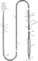
图1显示了依据本发明的球囊扩张导管的一个实施例的径向截面;Figure 1 shows a radial section of an embodiment of a balloon dilatation catheter according to the present invention;
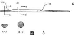
图2显示了图1中部分导管的详细描绘;Figure 2 shows a detailed depiction of some of the conduits in Figure 1;
图3显示了在图1导管中应用的过渡元件的明细截面;和Figure 3 shows a detailed cross-section of the transition element applied in the conduit of Figure 1; and
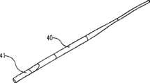
图4为图3中过渡元件的透视图。FIG. 4 is a perspective view of the transition element of FIG. 3 .
需注意这些图并未严格按比例绘制。特别是为了清楚显示,一些尺寸可能被大或缩小。图中相应的或相似的部分通常用相同的参考符号表示。Note that these figures are not strictly drawn to scale. Especially for clarity of display, some dimensions may be enlarged or reduced. Corresponding or similar parts in the figures are generally indicated by the same reference symbols.
图1的导管包含一近端体部10,在其最近端带有一个所谓的Luer装置1,用于以方便的方式将导管连接于扩张设备。所述设备能够将合适的扩张液体在压力作用下沿一个延伸于导管内部的扩张腔2运送至位于导管远端的扩张球囊23内部。The catheter of Figure 1 comprises a
实际应用时,该导管通过一个位于病人血管系统内的指引导管(未显示)行进至一支冠状动脉的入口。导管的近端体部10几乎完全沿着指引导管的长度延伸。为了提高可推送性和可操作性,该导管优选为相对刚性和僵硬以使作用于其近端的力量很少或不被损失地传送至远端。为此目的,依据本发明一种金属性管状元件11用作导管的近端体部。在本实施例中所述元件11由皮下注射用金属制成,被称为皮下管(hypotube),被任一光滑的覆盖层12覆盖以减少指引导管内壁和扩张导管之间的摩擦力。该覆盖层由薄层特氟纶或其它光滑可塑体或聚合物构成,但在本发明范围内其它材料也是可行的。这种皮下管装配极大程度减少了导管在指引导管内向前推送时弯曲或打结的倾向。然而,较小的冠状动脉弯曲的特性需要更多的柔软性以允许导管跟进这些血管的自然解剖。In practice, the catheter is advanced to the entrance of a coronary artery through a guide catheter (not shown) located within the patient's vasculature. The
因此导管包含一个更柔软以提供该种所谓跟进能力的远端体部20。在该实施例中,远端体部包含一个中间套管部分21和球囊部分22。远端体部20的21、22两部分都由一段低密度聚乙烯、聚次亚乙烯、尼龙或其它任何合适的足够柔软以跟进冠状动脉任何弯曲的可塑体等可塑性管形材料制成。中间套管部分直接连接于近端体部10并包含一导线腔30的近端入口31,该导线腔延伸于导管的远端体部20内部,与扩张腔并行或如本案一样与扩张腔共轴。导管的这部分在附图2中被更详细地显示。The catheter therefore comprises a distal body 20 which is more flexible to provide this so-called follow-through capability. In this embodiment, the distal body comprises an
指引导管腔30,在使用时,容纳导线3,导线3的大部分在导管的近端体部10旁延伸,其余部分在所述指引导管腔30内部延伸。导线3经过位于中间套管部分21、这样就位于近端体部的远端11和球囊部分22之间的导线腔入口31进入导线腔,通过位于导管远端顶部的导线腔出口32穿出导管。必要时,导线3用于将导管快速交换为另一个。当导线还在原位置时,导管可以被撤回以被另一导管代替,通过简单的穿导丝滑行,替代导管可以相对快速地行进到治疗部位。导线3从而引导导管直接到达正确位置。因为这个特点,本种导管常被称为快速交换穿导丝导管。The guiding
球囊部分带有一个可扩张球囊23。球囊23内部与全程延伸于luer装置以下、穿过近端体部和中间套管部分21至导管远端体部20的球囊部分22内部的扩张腔2通过液体连通。球囊由一个合适的预成型的能够经受住巨大内压的可塑性套管构成。当使用扩张压力时球囊将扩张至预定的扩张直径以相应地增宽血管。一个金属性支架元件,未显示,可以被预先放置在球囊上并与球囊一起扩张,此后支架将留在血管内以便在治疗结束后对血管壁提供持久的支撑。The balloon part has an
为了避免导管在由相对刚性的近端体部10向更为柔软的远端体部20转换的部位打结,一个过渡元件40被提供,用以支撑否则无支撑的金属皮下管11和导线入口31之间的导管区域。当导线3插入导线腔时,所述过渡元件40过渡导管体内部金属皮下管11和金属导线3之间的硬度差别。在本实施例中,过渡元件40包含一个柔软性通常居于近端体部10和远端体部20之间的金属性核心丝。芯线40通过铜焊、胶合或任何其它合适的方式牢固地连接于皮下管11。以大约286毫米的长度,芯线40完全延伸超过导线腔入口31。To avoid knotting of the catheter at the point of transition from the relatively rigid
依据本发明,皮下管11在其远端被割成薄片,以提供足够的接触面积使芯线40和皮下管11之间可靠结合。皮下管割成薄片的部分在预先确定的大约60~70毫米的长度上延伸,以容纳芯线40的近端。皮下管割成薄片的末端部分不仅提供了必需的接触面积更暴露出所述接触面,使它对于所用连接技巧而言容易进入。在该实施例中,芯线40通过紫外线固化黏合胶合于皮下管11。由于割成薄片的部分,整个接触面积可以暴露于紫外线固化辐射。并且,由于扩张液体在此割成薄片的区域不再限制于皮下管11的内部,它可以自由流过芯线40。结果,当球囊23扩张时,芯线40不对扩张液体产生明显的阻挡。According to the present invention, the
由于割成薄片的结构,皮下管11在其远端区域损失了相当大量的自身硬度。为了避免皮下管切割的远端部分打结,优选芯线40延伸进入管状皮下管即皮下管未切割的部分一些,以提供全面的支撑。在该实施例中,芯线40的近端位于近端体部10的管状部分内约3—5毫米。为了避免对扩张液体的明显阻挡(否则在这种方式下将可能产生),芯线40的近端带有一凹槽41,详见图3和4。该凹槽41大约5—7毫米长,去除了芯线横截面积的大约50%,看起来足可以允许扩张液体不受干扰地从luer装置1至球囊23,反之亦然。凹槽41位于与芯线40和近端体部10内壁之间的接触面的相对侧,目的是保留足够面积以可靠结合。还有其它代替凹槽41的体积减少方式可以被采用,从而为欲延伸一些进入近端体部10管状部分内部的过渡元件40的近端部分提供小于其远侧部分的横截面积。从液体动力学的角度而言,所述近端部分优选倾斜缓和的剖面,象凹槽或薄片之类,以避免当球囊23被扩张或缩小时扩张液体出现明显的湍流。Due to the sliced structure, the
优选地,过渡元件40从金属性近端体部至可塑性远端体部应有平滑转变的柔性。为此目的芯线40沿远侧方向逐渐变细。在本例中,芯线有一约0.31毫米的近端直径d1,见图3,在约279毫米的长度上逐渐变细至在其尖端约0.13毫米的远端直径d2。因为这种逐渐缩小的横截面积,芯线40的柔性逐渐增加,这样就获得至可塑性远端管部的非常平滑的柔性转变。Preferably, the
结果,本实施例的导管可以以非常好的可推送性和可操作性通过病人的血管系统行进,同时保持高的跟进能力,没有任何扭曲或打结的倾向。As a result, the catheter of this embodiment can be advanced through a patient's vasculature with very good pushability and maneuverability while maintaining high followability without any tendency to twist or kink.
虽然本发明仅按照一单一的实施例做了校详尽的描述,但应意识到本发明决不仅限于本实施例。相反,对于熟练的从业人员来说,不离开本发明的范围和宗旨很多改良和其它的实施例是可行的。同样的,前述实施例中应用的材料和尺寸可被其它已存在或新开发的材料或其它尺寸代替以达到最佳使用性能。其它类型过渡元件也可被使用,虽然该例中的芯线已取得很好结果。Although the invention has been described in detail in terms of a single embodiment, it should be appreciated that the invention is by no means limited to that embodiment. On the contrary, many modifications and other embodiments are apparent to the skilled practitioner without departing from the scope and spirit of this invention. Likewise, the materials and dimensions used in the foregoing embodiments can be replaced by other existing or newly developed materials or other dimensions to achieve the best performance. Other types of transition elements could also be used, although the core wire in this example has given good results.
Claims (8)
Applications Claiming Priority (2)
| Application Number | Priority Date | Filing Date | Title |
|---|---|---|---|
| US10/190,057 | 2002-07-03 | ||
| US10/190,057US7169162B2 (en) | 2002-07-03 | 2002-07-03 | Balloon catheter |
Publications (2)
| Publication Number | Publication Date |
|---|---|
| CN1665560A CN1665560A (en) | 2005-09-07 |
| CN100473433Ctrue CN100473433C (en) | 2009-04-01 |
Family
ID=29999787
Family Applications (1)
| Application Number | Title | Priority Date | Filing Date |
|---|---|---|---|
| CNB038159120AExpired - LifetimeCN100473433C (en) | 2002-07-03 | 2003-07-02 | Balloon catheter |
Country Status (9)
| Country | Link |
|---|---|
| US (3) | US7169162B2 (en) |
| EP (1) | EP1517720B1 (en) |
| JP (1) | JP2006507029A (en) |
| CN (1) | CN100473433C (en) |
| AT (1) | ATE326999T1 (en) |
| AU (1) | AU2003247782A1 (en) |
| DE (2) | DE60305494T8 (en) |
| ES (1) | ES2259770T3 (en) |
| WO (1) | WO2004004821A1 (en) |
Families Citing this family (34)
| Publication number | Priority date | Publication date | Assignee | Title |
|---|---|---|---|---|
| US7169162B2 (en)* | 2002-07-03 | 2007-01-30 | Orbusneich Medical, Inc. | Balloon catheter |
| AU2004237774B2 (en) | 2003-05-02 | 2009-09-10 | Surmodics, Inc. | Implantable controlled release bioactive agent delivery device |
| US8246974B2 (en) | 2003-05-02 | 2012-08-21 | Surmodics, Inc. | Medical devices and methods for producing the same |
| KR20070041726A (en)* | 2004-08-11 | 2007-04-19 | 가부시키가이샤 가네카 | Catheter |
| US7544201B2 (en)* | 2005-07-05 | 2009-06-09 | Futurematrix Interventional, Inc. | Rapid exchange balloon dilation catheter having reinforced multi-lumen distal portion |
| WO2007035938A2 (en) | 2005-09-22 | 2007-03-29 | Medivas, Llc | BIS-(α-AMINO)-DIOL-DIESTER-CONTAINING POLY(ESTER AMIDE) AND POLY(ESTER URETHANE) COMPOSITIONS AND METHODS OF USE |
| WO2007059281A1 (en)* | 2005-11-16 | 2007-05-24 | William Cook Europe Aps | Rapid exchange balloon catheter and method for making same |
| US20070167877A1 (en)* | 2006-01-17 | 2007-07-19 | Euteneuer Charles L | Medical catheters and methods |
| US20080306427A1 (en)* | 2007-06-05 | 2008-12-11 | Cook Incorporated | Chronic Hemodialysis Catheter with Balloon |
| JP2009089806A (en)* | 2007-10-05 | 2009-04-30 | Asahi Intecc Co Ltd | Balloon catheter |
| EP2282699A4 (en)* | 2008-05-10 | 2015-05-06 | Orbusneich Medical Inc | Sleeves for positioning a stent on a delivery balloon cathether system |
| US9011511B2 (en)* | 2009-02-20 | 2015-04-21 | Boston Scientific Scimed, Inc. | Balloon catheter |
| US8057430B2 (en) | 2009-02-20 | 2011-11-15 | Boston Scientific Scimed, Inc. | Catheter with skived tubular member |
| EP2398547A1 (en)* | 2009-02-20 | 2011-12-28 | Boston Scientific Scimed, Inc. | Torqueable balloon catheter |
| EP2429453B1 (en)* | 2009-05-14 | 2021-01-27 | Orbusneich Medical Pte. Ltd | Self-expanding stent with polygon transition zone |
| DE102010006187B4 (en) | 2010-01-29 | 2017-11-16 | Acandis Gmbh & Co. Kg | Medical catheter for delivering a self-expanding non-preloaded stent |
| JP4963327B2 (en)* | 2010-06-11 | 2012-06-27 | 朝日インテック株式会社 | Balloon catheter storage device |
| WO2012148969A2 (en)* | 2011-04-25 | 2012-11-01 | Brian Kelly | Apparatus and methods related to constrained deployment of cryogenic balloons for limited cryogenic ablation of vessel walls |
| EP2768568B1 (en) | 2011-10-18 | 2020-05-06 | Boston Scientific Scimed, Inc. | Integrated crossing balloon catheter |
| WO2013086698A1 (en)* | 2011-12-14 | 2013-06-20 | 东莞市迪凯精密管材有限公司 | Balloon dilatation catheter with anti-twist outer tube |
| CA2895165A1 (en) | 2012-12-18 | 2014-06-26 | Volcano Corporation | Transitional region having cuts and a skive for an imaging catheter |
| DE202014102615U1 (en) | 2014-06-04 | 2014-06-30 | Acandis Gmbh & Co. Kg | Medical catheter |
| JP6342843B2 (en)* | 2015-05-01 | 2018-06-13 | 朝日インテック株式会社 | Balloon catheter |
| WO2016191415A1 (en) | 2015-05-26 | 2016-12-01 | Vascular Solutions, Inc. | Guidewire fixation |
| JP7027319B2 (en) | 2016-02-08 | 2022-03-01 | オーバスネイチ・メディカル・プライベート・リミテッド | Drug-eluting balloon |
| US10792477B2 (en) | 2016-02-08 | 2020-10-06 | Orbusneich Medical Pte. Ltd. | Drug eluting balloon |
| CN107432980A (en)* | 2016-05-25 | 2017-12-05 | 孙英贤 | The foley's tube of flexible joint is provided between a kind of head end and sacculus |
| US10751514B2 (en) | 2016-12-09 | 2020-08-25 | Teleflex Life Sciences Limited | Guide extension catheter |
| EP3586899A1 (en) | 2018-06-25 | 2020-01-01 | Biotronik Ag | Catheter, in particular balloon catheter, and a method for manufacturing the same |
| US11524142B2 (en) | 2018-11-27 | 2022-12-13 | Teleflex Life Sciences Limited | Guide extension catheter |
| CN111265760B (en)* | 2018-12-04 | 2023-05-16 | 东莞市先健医疗有限公司 | Balloon catheter and manufacturing method thereof |
| EP3897802A4 (en) | 2018-12-19 | 2022-10-05 | Teleflex Life Sciences Limited | Guide extension catheter |
| WO2020146035A1 (en) | 2019-01-07 | 2020-07-16 | Teleflex Life Sciences Limited | Guide extension catheter |
| CN117258117B (en)* | 2023-11-07 | 2024-03-22 | 恒壹(北京)医疗科技有限公司 | Anchoring guide wire device |
Citations (7)
| Publication number | Priority date | Publication date | Assignee | Title |
|---|---|---|---|---|
| US5300025A (en)* | 1992-09-30 | 1994-04-05 | Advanced Cardiovascular Systems, Inc. | Dilatation catheter having a coil supported inflation lumen |
| DE4415107A1 (en)* | 1993-04-29 | 1994-11-03 | Scimed Life Systems Inc | Single operator replacement catheter with a distal catheter shaft section |
| US5387193A (en)* | 1994-02-09 | 1995-02-07 | Baxter International Inc. | Balloon dilation catheter with hypotube |
| WO1995009668A1 (en)* | 1993-10-07 | 1995-04-13 | Boston Scientific Corporation | Dilatation catheter |
| US5634902A (en)* | 1995-02-01 | 1997-06-03 | Cordis Corporation | Dilatation catheter with side aperture |
| EP1084728A1 (en)* | 1999-09-15 | 2001-03-21 | Angiodynamics Limited | A balloon catheter |
| US20010011180A1 (en)* | 1996-10-24 | 2001-08-02 | Ave Connaught | Reinforced monorail balloon catheter |
Family Cites Families (4)
| Publication number | Priority date | Publication date | Assignee | Title |
|---|---|---|---|---|
| JP3970341B2 (en)* | 1994-06-20 | 2007-09-05 | テルモ株式会社 | Vascular catheter |
| US6575958B1 (en)* | 2000-05-23 | 2003-06-10 | Advanced Cardiovascular Systems, Inc. | Catheter with improved transition |
| JP4774144B2 (en)* | 2000-07-18 | 2011-09-14 | 川澄化学工業株式会社 | Balloon catheter |
| US7169162B2 (en)* | 2002-07-03 | 2007-01-30 | Orbusneich Medical, Inc. | Balloon catheter |
- 2002
- 2002-07-03USUS10/190,057patent/US7169162B2/ennot_activeExpired - Lifetime
- 2003
- 2003-07-02CNCNB038159120Apatent/CN100473433C/ennot_activeExpired - Lifetime
- 2003-07-02WOPCT/US2003/021006patent/WO2004004821A1/enactiveIP Right Grant
- 2003-07-02DEDE60305494Tpatent/DE60305494T8/enactiveActive
- 2003-07-02EPEP03763181Apatent/EP1517720B1/ennot_activeExpired - Lifetime
- 2003-07-02AUAU2003247782Apatent/AU2003247782A1/ennot_activeAbandoned
- 2003-07-02ATAT03763181Tpatent/ATE326999T1/ennot_activeIP Right Cessation
- 2003-07-02ESES03763181Tpatent/ES2259770T3/ennot_activeExpired - Lifetime
- 2003-07-02DEDE60305494Apatent/DE60305494D1/ennot_activeExpired - Lifetime
- 2003-07-02JPJP2004519858Apatent/JP2006507029A/enactivePending
- 2007
- 2007-01-30USUS11/668,594patent/US20080200875A1/ennot_activeAbandoned
- 2009
- 2009-07-21USUS12/506,750patent/US20100168669A1/ennot_activeAbandoned
Patent Citations (7)
| Publication number | Priority date | Publication date | Assignee | Title |
|---|---|---|---|---|
| US5300025A (en)* | 1992-09-30 | 1994-04-05 | Advanced Cardiovascular Systems, Inc. | Dilatation catheter having a coil supported inflation lumen |
| DE4415107A1 (en)* | 1993-04-29 | 1994-11-03 | Scimed Life Systems Inc | Single operator replacement catheter with a distal catheter shaft section |
| WO1995009668A1 (en)* | 1993-10-07 | 1995-04-13 | Boston Scientific Corporation | Dilatation catheter |
| US5387193A (en)* | 1994-02-09 | 1995-02-07 | Baxter International Inc. | Balloon dilation catheter with hypotube |
| US5634902A (en)* | 1995-02-01 | 1997-06-03 | Cordis Corporation | Dilatation catheter with side aperture |
| US20010011180A1 (en)* | 1996-10-24 | 2001-08-02 | Ave Connaught | Reinforced monorail balloon catheter |
| EP1084728A1 (en)* | 1999-09-15 | 2001-03-21 | Angiodynamics Limited | A balloon catheter |
Also Published As
| Publication number | Publication date |
|---|---|
| ATE326999T1 (en) | 2006-06-15 |
| JP2006507029A (en) | 2006-03-02 |
| WO2004004821A1 (en) | 2004-01-15 |
| US20080200875A1 (en) | 2008-08-21 |
| AU2003247782A1 (en) | 2004-01-23 |
| US20040006360A1 (en) | 2004-01-08 |
| DE60305494D1 (en) | 2006-06-29 |
| EP1517720B1 (en) | 2006-05-24 |
| CN1665560A (en) | 2005-09-07 |
| US20100168669A1 (en) | 2010-07-01 |
| DE60305494T8 (en) | 2007-06-21 |
| DE60305494T2 (en) | 2006-11-02 |
| EP1517720A1 (en) | 2005-03-30 |
| ES2259770T3 (en) | 2006-10-16 |
| US7169162B2 (en) | 2007-01-30 |
Similar Documents
| Publication | Publication Date | Title |
|---|---|---|
| CN100473433C (en) | Balloon catheter | |
| US5720724A (en) | Intravascular catheter with distal guide wire lumen and transition member | |
| EP1234594B1 (en) | Catheter shaft | |
| US6273879B1 (en) | Balloon catheter with distal guide wire lumen | |
| JP3530189B2 (en) | Anatomically matched steerable PTCA guidewire | |
| US6004291A (en) | Intravascular catheter with distal guide wire lumen and transition | |
| US5556382A (en) | Balloon perfusion catheter | |
| US5545138A (en) | Adjustable stiffness dilatation catheter | |
| EP0279959B1 (en) | Dilatation catheter with thin guide wire | |
| EP0580845B1 (en) | Intravascular catheter with distal guide wire lumen | |
| JPH09511159A (en) | Balloon dilatation catheter with hypotube | |
| US20050197669A1 (en) | Rapid exchange balloon catheter with braided shaft | |
| US7189215B2 (en) | Catheter with full-length core wire shaft for core wire interchangeability | |
| US20040092868A1 (en) | Catheter with full-length core wire shaft for core wire interchangeability | |
| US20090209941A1 (en) | Implant deployment catheter | |
| KR20050016954A (en) | Ballon catheter |
Legal Events
| Date | Code | Title | Description |
|---|---|---|---|
| C06 | Publication | ||
| PB01 | Publication | ||
| C10 | Entry into substantive examination | ||
| SE01 | Entry into force of request for substantive examination | ||
| C14 | Grant of patent or utility model | ||
| GR01 | Patent grant | ||
| TR01 | Transfer of patent right | ||
| TR01 | Transfer of patent right | Effective date of registration:20171123 Address after:No. 79, Anshun Road, Singapore, No. 79 Patentee after:ORBUSNEICH MEDICAL, Inc. Address before:American Florida Patentee before:ORBUS MEDICAL TECHNOLOGIES, Inc. | |
| CP02 | Change in the address of a patent holder | ||
| CP02 | Change in the address of a patent holder | Address after:Singapore, Singapore Patentee after:ORBUSNEICH MEDICAL, Inc. Address before:No. 79, Anshun Road, Singapore, No. 79 Patentee before:ORBUSNEICH MEDICAL, Inc. | |
| CX01 | Expiry of patent term | ||
| CX01 | Expiry of patent term | Granted publication date:20090401 |